EP1528639B1 - Steckverbindergehäuse mit Kurzschlussbrücke - Google Patents
Steckverbindergehäuse mit Kurzschlussbrücke Download PDFInfo
- Publication number
- EP1528639B1 EP1528639B1 EP04017808A EP04017808A EP1528639B1 EP 1528639 B1 EP1528639 B1 EP 1528639B1 EP 04017808 A EP04017808 A EP 04017808A EP 04017808 A EP04017808 A EP 04017808A EP 1528639 B1 EP1528639 B1 EP 1528639B1
- Authority
- EP
- European Patent Office
- Prior art keywords
- contact
- connector
- longitudinal axis
- housing
- connector housing
- Prior art date
- Legal status (The legal status is an assumption and is not a legal conclusion. Google has not performed a legal analysis and makes no representation as to the accuracy of the status listed.)
- Expired - Lifetime
Links
- 230000013011 mating Effects 0.000 claims description 15
- 238000003780 insertion Methods 0.000 claims description 11
- 230000037431 insertion Effects 0.000 claims description 11
- 230000004308 accommodation Effects 0.000 claims description 7
- 239000004020 conductor Substances 0.000 claims description 3
- 230000000717 retained effect Effects 0.000 claims 1
- 238000009423 ventilation Methods 0.000 description 5
- 241000047428 Halter Species 0.000 description 4
- 238000005452 bending Methods 0.000 description 2
- 230000002349 favourable effect Effects 0.000 description 2
- 239000000463 material Substances 0.000 description 2
- RYGMFSIKBFXOCR-UHFFFAOYSA-N Copper Chemical compound [Cu] RYGMFSIKBFXOCR-UHFFFAOYSA-N 0.000 description 1
- 239000011248 coating agent Substances 0.000 description 1
- 238000000576 coating method Methods 0.000 description 1
- 238000004891 communication Methods 0.000 description 1
- 229910052802 copper Inorganic materials 0.000 description 1
- 239000010949 copper Substances 0.000 description 1
- 239000012777 electrically insulating material Substances 0.000 description 1
- 230000003100 immobilizing effect Effects 0.000 description 1
- 238000011144 upstream manufacturing Methods 0.000 description 1
Images


Classifications
-
- H—ELECTRICITY
- H01—ELECTRIC ELEMENTS
- H01R—ELECTRICALLY-CONDUCTIVE CONNECTIONS; STRUCTURAL ASSOCIATIONS OF A PLURALITY OF MUTUALLY-INSULATED ELECTRICAL CONNECTING ELEMENTS; COUPLING DEVICES; CURRENT COLLECTORS
- H01R13/00—Details of coupling devices of the kinds covered by groups H01R12/70 or H01R24/00 - H01R33/00
- H01R13/66—Structural association with built-in electrical component
- H01R13/70—Structural association with built-in electrical component with built-in switch
- H01R13/701—Structural association with built-in electrical component with built-in switch the switch being actuated by an accessory, e.g. cover, locking member
-
- H—ELECTRICITY
- H01—ELECTRIC ELEMENTS
- H01R—ELECTRICALLY-CONDUCTIVE CONNECTIONS; STRUCTURAL ASSOCIATIONS OF A PLURALITY OF MUTUALLY-INSULATED ELECTRICAL CONNECTING ELEMENTS; COUPLING DEVICES; CURRENT COLLECTORS
- H01R13/00—Details of coupling devices of the kinds covered by groups H01R12/70 or H01R24/00 - H01R33/00
- H01R13/40—Securing contact members in or to a base or case; Insulating of contact members
- H01R13/42—Securing in a demountable manner
- H01R13/422—Securing in resilient one-piece base or case, e.g. by friction; One-piece base or case formed with resilient locking means
- H01R13/4223—Securing in resilient one-piece base or case, e.g. by friction; One-piece base or case formed with resilient locking means comprising integral flexible contact retaining fingers
-
- H—ELECTRICITY
- H01—ELECTRIC ELEMENTS
- H01R—ELECTRICALLY-CONDUCTIVE CONNECTIONS; STRUCTURAL ASSOCIATIONS OF A PLURALITY OF MUTUALLY-INSULATED ELECTRICAL CONNECTING ELEMENTS; COUPLING DEVICES; CURRENT COLLECTORS
- H01R13/00—Details of coupling devices of the kinds covered by groups H01R12/70 or H01R24/00 - H01R33/00
- H01R13/40—Securing contact members in or to a base or case; Insulating of contact members
- H01R13/42—Securing in a demountable manner
- H01R13/436—Securing a plurality of contact members by one locking piece or operation
- H01R13/4364—Insertion of locking piece from the front
- H01R13/4365—Insertion of locking piece from the front comprising a temporary and a final locking position
Definitions
- the invention relates to a connector housing comprising a longitudinal axis, a first housing portion having a front end face and a rear end, at least two receiving chambers extending parallel to the longitudinal axis for receiving an electrical contact element having a pin, wherein the receiving chambers each have an insertion opening for the associated contact element and having an open end face for the front end opening for the plug pin, an elastic latch arm per receiving chamber for fixing the contact element in the receiving chamber, a second housing portion which is integrally formed with the first housing portion forms a receiving space into which a portion of a housing of a mating connector can be introduced, which has a contact socket having contact elements, which are each electrically conductively connected to the contact elements and a plug connection comprising the Ste connector housing and an associated mating connector. More particularly, the invention relates to a connector housing having a shorting bridge for shorting the contact elements provided with a pin.
- EP 1 235 306 A2 describes such a connector housing with receiving chambers for contact elements with contact sockets, wherein the contact sockets are inserted through an insertion opening into the receiving chambers and via an opening in the front end face of the connector housing for the entry of a Connector pin are accessible.
- the contact elements are each set in the receiving chambers by a locking arm, which engages behind an edge on the associated contact element.
- a front holder is provided which enters into a gap between a wall of the first housing portion of the connector housing and the outer surface of the locking arms, so that they are fixed.
- the problem is that when inserting the contact element in the associated receiving chamber, the contact arms of the shorting bridge are in the rebounded state and thus are in the range of motion exiting the end face of the housing connector pins, so that the risk of misalignment of the contact element is.
- a special coating is provided on the connector pins to improve contact, damage to the surface of the connector pins may occur during the relative movement between the connector pins and the contact region of the contact arms.
- the expended for the assembly of the contact elements force is correspondingly high, since the spring force of the contact arms is overcome.
- the contact elements are made of a highly conductive material, for example, a copper material that is relatively soft, the connector pins can be bent.
- a connector housing in which a fuse element is provided which forms a secondary latch for both contact elements and for the shorting bridge in the connector housing.
- This element can be inserted transversely to the longitudinal axis into a recess of the connector housing and can be fixed in two different positions via latching means. In the first position, this securing element is held so that both the contact elements and the shorting bridge can be inserted into the connector housing so that they are fixed by the locking means provided in the connector housing. Thereafter, the securing element can be transferred to the final holding position, in which it secures both the shorting bridge and the individual contact elements in addition, so that a total of a double lock given is.
- a locking element in the form of a flap is provided, which is pivotally mounted on the connector housing and having first locking means which come into contact with second locking means on the mating connector and lock the connector housing to the mating connector.
- This locking flap is additionally provided with a release element that brings the shorting bridge out of contact with the contact elements in the locked state of the locking flap with the mating connector.
- the invention is therefore an object of the invention to provide a connector housing in which the contact elements are easy to assemble and the risk of damage to the same is not given despite the presence of a shorting bridge.
- An advantage of this design is that the known in itself for the setting of locking arms front holder can be additionally used to hold the contact arms of the shorting bridge initially in a raised release position during assembly of the contact elements, so that they are not connected to the plug pins Contact elements can come into contact. As a result, the assembly of the contact elements is facilitated overall. The insertion thus needs to be done only by overcoming the spring force of the locking arm. The plug pins themselves are not loaded at the tip when exiting the outlet opening in the end face of the first housing section, so that no damage can occur.
- the front holder can be transferred to its end position, so that the contact arms are released and are introduced transversely to the longitudinal axis of the connector pins.
- the contact arms of the shorting bridge contact the connector pins in a region close to the support, so that there is no risk of bending them.
- the front holder is designed like a frame and is at least partially sunk in the end position in the end position.
- a connector comprising a connector housing according to one of the claims, which relate to the connector housing, and a mating connector, which is associated with at least a second L comparativelement which brings the contact arms when connecting to the connector housing out of contact with the connector pins.
- a connector housing 2 can be seen, which has the longitudinal axis 1.
- the connector housing 2 comprises a first housing section 3 and a second housing section 4.
- the first housing section 3 extends between a front end face 5 and a rear end 6.
- two receiving chambers 7 are arranged, as in the present embodiment, a bipolar embodiment.
- the two receiving chambers 7 are parallel to the longitudinal axis, but only one of which is visible.
- the second receiving chamber is located behind the visible receiving chamber 7, ie behind the drawing plane.
- the receiving chamber 7 is open via an insertion 9 and an outlet bore 8 to the rear end 6.
- an outlet opening 10 is present, which is in communication with the receiving chamber 7.
- a locking arm 11 is provided per receiving chamber 7, which is integrally formed with the first housing portion 3, but is separated from it so that it can be elastically deformed. It has a locking projection 12 which, in the relaxed state of the locking arm 11, that is, when no force is exerted on it, protrudes into the region of the receiving chamber 7. Between the outer surfaces 15 of the locking arms 11 and the wall 14 of the first housing portion 3, a gap 13 is formed, in which the locking arm 11 can be elastically displaced.
- the first housing section 3 integrally formed second housing portion 4 forms a receiving space 16 for a housing portion of a mating connector.
- This receiving space 16 is arranged upstream of the front end face 5 of the first housing section 3.
- a fixing set 17 is provided transversely to the longitudinal axis 1 and offset thereto, on which the holding section of an electrically conductive shorting bridge 18 is accommodated.
- the setting approach 17 is over the front end surface 5 in the receiving space 16 before, and extends substantially parallel to the longitudinal axis 1.
- the shorting bridge 18 has in the proposed two-pole embodiment, two contact arms 19, of which only one can be seen.
- the second contact arm 19 is located in the plane behind the visible contact arm 19 and is spaced therefrom, so that both can spring separately.
- each contact arm 19 extends in the direction of the front end face 5 into a recess in the end face 5, and that the longitudinal axis 1 approximately , and has towards the free end a projection 19a and a again away from the longitudinal axis 1 portion.
- the connector housing 2 is associated with a front holder 20 which is located in the receiving space 16 in the initial position.
- the front holder 20 has two first vent elements 22. These each have an in the direction of the rear end 6 obliquely to the longitudinal axis 1 to be extended Lvid Chemistry 22a and then a holding surface 22b.
- the front holder 20 has struts 23 which extend from its front, designed as a frame 24 portion in the direction of the rear end 6 and carry a transversely to the longitudinal axis 1 extending cross member 22.
- the front holder 20 is made of an electrically insulating material.
- the first louver elements 22 each contact one of the contact arms 19 with the projection 19a provided in the region of the outwardly angled gate and lift the contact arms 19 on further insertion of the holder 20 in the direction of the rear end 6 by sliding the lugs 19a of the contact arms 19 on the ventilation surfaces 22a, so that they are supported in a direction transverse to the longitudinal axis 1 clearly outside the outlet openings 10 in the front end face 5 on the support surfaces 22b adjoining the ventilation surfaces 22a.
- the front holder 20 remains until complete assembly of contact elements 25, which are each connected to a cable 28.
- the insertion of the contact elements 25 takes place through the outlet bore 8 via the insertion opening 9 in the receiving chamber 7, wherein the elastic locking arm 11 with his Bolt projection 12 is displaced from the region of the receiving chamber 7 in the gap 13.
- the molded-in plug pin 26 passes through the outlet opening 10 outwards into the receiving space 16 via the front end face 5. Since the contact arms 19 are held away from the exit openings 10 by the front holder 20, the insertion can be done easily and without a frictional contact or a bending stress by the contact arms 19.
- the elastically deformed locking arm 11 can again assume its relaxed position, in which its locking projection 12 sits in front of a retaining edge 27 of the contact element 25.
- a seal 29 is arranged between the cable 28 and the wall of the outlet bore 8, to achieve a water- and moisture-proof connection.
- the front holder 20 When all the contact elements 25 are inserted as described above and secured by the associated latch arms 11 in the receiving chambers 7, the front holder 20 can be moved along the longitudinal axis 1 towards the rear end 6, wherein the first Lsymmetricetti 22 come out of contact with the contact arms 19 and the cross member 24 enters the gap 13 between the wall 14 of the first housing portion 3 and the outer surface 15 of the locking arms 11, so that the gap 13 is filled in a direction transverse to the longitudinal axis 1. As a result, the locking arms 11 are fixed in their locked position. In this case, the front holder 20 assumes the position shown in Fig. 2, wherein the frame portion of the holder 20 is received in the recess 21 of the end face 5, so that it does not project beyond the front end face 5. From Fig. 2 is further seen that the contact arms 19 have come into contact with the connector pins 26 of the contact elements 25.
- the front holder 20 is shown as a single part, which comprises a in the end position in the recess 21 entering frame portion and extending parallel to the longitudinal axis 1 struts 23 which project from the frame portion and carry at its free ends the cross member 24 which runs transversely to the longitudinal axis 1.
- the first vent elements 22 can be seen, which are each provided with a vent surface 22a and a holding surface 22b.
- a mating connector 30 is shown having a portion 31, which enters the receiving space 16 of the connector housing 2 when connecting both together.
- this section 31 are also receiving chambers in which, however, are designed as contact sockets 32 designed contact elements.
- the mating connector 30 is associated with a second L separatedelement 33, that an obliquely from the longitudinal axis 1 is removed sliding surface 34 which comes into contact with the outwardly angled arm portions of the contact arms 19 of the shorting bridge 18 during insertion of the portion 31 in the receiving space 16, so that the contact arms 19 are lifted from the connector pins 26 from the position shown in Fig. 2, before the connector pins 26 can electrically conductively come into contact with the contact sockets 32.
- the short-circuiting bridge 18 may also has a corresponding number of contact arms 19. Furthermore, if a plurality of parallel rows of receiving chambers 7 are provided, a corresponding number of short-circuiting bridges 18 may be provided.
Landscapes
- Connector Housings Or Holding Contact Members (AREA)
Description
- Die Erfindung betrifft ein Steckverbindergehäuse umfassend eine Längsachse, einen ersten Gehäuseabschnitt mit einer vorderen Stirnfläche und einem hinteren Ende, mindestens zwei parallel zur Längsachse verlaufenden Aufnahmekammern zur jeweiligen Aufnahme eines elektrischen Kontaktelements, das einen Steckerstift aufweist, wobei die Aufnahmekammern jeweils eine Einführöffnung für das zugehörige Kontaktelement und eine zur vorderen Stirnfläche offene Austrittsöffnung für den Steckerstift aufweisen, einem elastischen Riegelarm je Aufnahmekammer zur Festsetzung des Kontaktelements in der Aufnahmekammer, einen zweiten Gehäuseabschnitt, der mit dem ersten Gehäuseabschnitt einstückig ausgebildet ist, einen Aufnahmeraum bildet, in den ein Abschnitt eines Gehäuses eines Gegensteckverbinders einführbar ist, der eine Kontaktbuchse aufweisende Kontaktelemente besitzt, die mit den Kontaktelementen jeweils elektrisch leitend verbindbar sind und eine Steckverbindung umfassend das Steckverbindergehäuse und einen zugehörigen Gegensteckverbinder. Die Erfindung betrifft insbesondere ein Steckverbindergehäuse mit einer Kurzschlussbrücke zum Kurzschließen der mit einem Steckerstift versehenen Kontaktelemente.
- Die EP 1 235 306 A2 beschreibt ein solches Steckverbindergehäuse mit Aufnahmekammern für Kontaktelemente mit Kontaktbuchsen, wobei die Kontaktbuchsen durch eine Einführöffnung in die Aufnahmekammern eingeführt werden und über eine Öffnung in der vorderen Stirnfläche des Steckverbindergehäuses für den Eintritt eines Steckerstiftes zugänglich sind. Die Kontaktelemente werden in den Aufnahmekammern jeweils durch einen Riegelarm festgesetzt, der eine Kante am zugehörigen Kontaktelement hintergreift. Zusätzlich ist ein vorderer Halter vorgesehen, der in einen Spalt zwischen einer Wand des ersten Gehäuseabschnittes des Steckverbindergehäuses und der Außenfläche der Riegelarme eintritt, so dass diese festgesetzt sind.
- Bei Steckverbindergehäusen mit einer Kurzschlussbrücke besteht das Problem, dass beim Einführen des Kontaktelements in die zugehörige Aufnahmekammer sich die Kontaktarme der Kurzschlussbrücke im ausgefederten Zustand befinden und dadurch im Bewegungsbereich der aus der Stirnfläche des Gehäuses austretenden Steckerstifte stehen, so dass die Gefahr der Schiefstellung des Kontaktelementes gegeben ist. Darüber hinaus besteht die Gefahr, dass dann, wenn eine besondere Beschichtung an den Steckerstiften zur Kontaktverbesserung vorgesehen ist, bei der Relativbewegung zwischen den Steckerstiften und dem Kontaktbereich der Kontaktarme eine Beschädigung der Oberfläche der Steckerstifte eintreten kann. Ferner ist die für die Montage der Kontaktelemente aufzuwendende Kraft entsprechend hoch, da die Federkraft der Kontaktarme zu überwinden ist. Im übrigen können dann, wenn die Kontaktelemente aus einem hochleitenden Material hergestellt sind, beispielsweise aus einem Kupferwerkstoff, der relativ weich ist, die Steckerstifte verbogen werden.
- In der EP-A-0 678 938 ist ein Steckverbindergehäuse beschrieben, bei dem ein Sicherungselement vorgesehen ist, das eine Zweitverriegelung sowohl für Kontaktelemente als auch für die Kurzschlussbrücke im Steckverbindergehäuse bildet. Dieses Element ist quer zur Längsachse in eine Ausnehmung des Steckverbindergehäuses einschiebbar und über Rastmittel in zwei verschiedenen Positionen festlegbar. In der ersten Position ist dieses Sicherungselement so gehalten, dass sowohl die Kontaktelemente als auch die Kurzschlussbrücke in das Steckverbindergehäuse so eingeschoben werden können, dass sie von dem im Steckverbindergehäuse vorgesehenen Riegelmittel festgesetzt werden. Danach ist das Sicherungselement in die endgültige Halteposition überführbar, in welcher es sowohl die Kurzschlussbrücke als auch die einzelnen Kontaktelemente zusätzlich sichert, so dass insgesamt eine Zweifachverriegelung gegeben ist. In dieser entgültigen Position beaufschlagt das Sicherungselement die Kurzschlussbrücke derart, dass sie mit den Kontaktelementen in Kontakt tritt. Zusätzlich ist ein Verriegelungselement in Form einer Klappe vorgesehen, welche schwenkbar am Steckverbindergehäuse befestigt ist und erste Verriegelungsmittel aufweist, die mit zweiten Verriegelungsmitteln am Gegensteckverbinder in Kontakt treten und das Steckverbindergehäuse zum Gegenstecker verriegeln. Diese Verriegelungsklappe ist zusätzlich mit einem Löseelement versehen, das im verriegelten Zustand der Verriegelungsklappe mit dem Gegensteckverbinder die Kurzschlussbrücke außer Kontakt zu den Kontaktelementen bringt.
- Der Erfindung liegt daher die Aufgabe zugrunde, ein Steckverbindergehäuse zu schaffen, bei dem die Kontaktelemente einfach zu montieren sind und die Gefahr der Beschädigung derselben trotz des Vorhandenseins einer Kurzschlussbrücke nicht gegeben ist.
- Diese Aufgabe wird erfindungsgemäß durch ein Steckverbindergehäuse gelöst, das gekennzeichnet ist durch
- eine Kurzschlussbrücke, die
- aus einem elektrisch leitenden Material besteht,
- im ersten Gehäuseabschnitt festgelegt ist,
- für jedes Kontaktelement einen elastisch federnden Kontaktarm umfasst, wobei die Kontaktarme miteinander verbunden sind und dazu dienen, mit den Steckerstiften in Kontakt zu treten,
- und einen vorderen Halter, der
- zwischen einer Anfangsposition und einer Endposition entlang der Längsachse verlagerbar ist,
- mindestens ein erstes Lüftelement aufweist, das in der Anfangsposition die Kontaktarme in einer Lüftposition hält und in der Endposition diese unbeaufschlagt lässt, so dass diese in Kontakt zu den Steckerstiften treten.
- Von Vorteil bei dieser Ausbildung ist, dass der an sich für das Festsetzen von Riegelarmen bekannte vordere Halter zusätzlich genutzt werden kann, um bei der Montage der Kontaktelemente die Kontaktarme der Kurzschlussbrücke zunächst in einer abgehobenen Lüftposition zu halten, so dass diese nicht mit den Steckerstiften der Kontaktelemente in Kontakt treten können. Dadurch wird die Montage der Kontaktelemente insgesamt erleichtert. Das Einschieben braucht also nur unter Überwindung der Federkraft des Riegelarmes zu erfolgen. Die Steckerstifte selbst werden beim Austreten aus der Austrittsöffnung in der Stirnfläche des ersten Gehäuseabschnittes nicht an der Spitze belastet, so dass auch keine Beschädigungen eintreten können. Erst dann, wenn sämtliche Kontaktelemente richtig montiert sind, d.h., gewährleistet ist, dass die Riegelarme die richtige Riegelposition einnehmen, kann der vordere Halter in seine Endposition überführt werden, so dass die Kontaktarme freigegeben werden und quer zur Längsachse an die Steckerstifte herangeführt werden. Normalerweise treten die Kontaktarme der Kurzschlussbrücke in einem unterstützungsnahen Bereich mit den Steckerstiften in Kontakt, so dass die Gefahr eines Verbiegens derselben dabei nicht gegeben ist.
- Günstig ist, wenn je Kontaktarm ein erstes Lüftelement vorgesehen ist.
- Vorzugsweise ist der vordere Halter rahmenartig gestaltet und wird in der Endposition zumindest teilweise in der vorderen Stirnfläche versenkt aufgenommen.
- Zur Verbesserung der Führung weist der vordere Halter sich parallel zur Längsachse erstreckende Streben auf, die die Traverse tragen.
- Besonders günstig ist, wenn die Traverse in der Endposition des vorderen Halters einen Spalt zwischen einer Wand des ersten Gehäuseabschnittes und der den Aufnahmekammern abgewandten Außenflächen der Riegelarme in einer Richtung quer zur Längsachse ausfüllt. Hierdurch werden die Riegelarme an einem Ausweichen aus der Riegelposition gehindert, so dass eine doppelte Sicherung der Kontaktelemente in ihrer Position in den Aufnahmekammern gegeben ist. So kann selbst beim Auftreten von Zugkräften auf ein mit dem Kontaktelement verbundenes Kabel im Sinne des Ausziehens desselben aus dem Steckverbindergehäuse kein Lösen eintreten.
- Gelöst wird die Aufgabe ferner durch eine Steckverbindung umfassend ein Steckverbindergehäuse nach einem der Ansprüche, die sich auf das Steckverbindergehäuse beziehen, und einen Gegensteckverbinder, dem wenigstens ein zweites Lüftelement zugeordnet ist, das die Kontaktarme beim Verbinden mit dem Steckverbindergehäuse außer Kontakt zu den Steckerstiften bringt.
- Ein bevorzugtes Ausführungsbeispiel des Steckverbindergehäuses und eines Gegensteckverbinders ist in der Zeichnung dargestellt.
- Es zeigt:
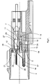
- Fig. 1
- einen Längsschnitt durch ein erfindungsgemäßes Steckverbindergehäuse in der Ebene einer Aufnahmekammer, wobei sich der vordere Halter in einer Anfangsposition befindet,
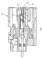
- Fig. 2
- einen Längsschnitt entsprechend dem von Fig. 1, wobei jedoch sich der vordere Halter in der Endposition befindet,
- Fig. 3
- eine perspektivische Ansicht eines vorderen Halters als Einzelteil und
- Fig. 4
- einen Längsschnitt durch einen Gegensteckverbinder mit einem Lüftelement.
- Aus Fig. 1 ist ein Steckverbindergehäuse 2 ersichtlich, das die Längsachse 1 aufweist. Das Steckverbindergehäuse 2 umfaßt einen ersten Gehäuseabschnitt 3 und einen zweiten Gehäuseabschnitt 4. Der erste Gehäuseabschnitt 3 erstreckt sich zwischen einer vorderen Stirnfläche 5 und einem hinteren Ende 6. In dem ersten Gehäuseabschnitt 3 sind zwei Aufnahmekammern 7 angeordnet, da es sich bei vorliegenden Ausführungsbeispiel um eine zweipolige Ausführungsform handelt. Die zwei Aufnahmekammern 7 verlaufen parallel zur Längsachse, von denen jedoch nur eine sichtbar ist. Die zweite Aufnahmekammer befindet sich hinter der sichtbaren Aufnahmekammer 7, also hinter der Zeichenebene.
- Die Aufnahmekammer 7 ist über eine Einführöffnung 9 und eine Austrittsbohrung 8 zum hinteren Ende 6 offen. In der vorderen Stirnfläche 5 ist eine Austrittsöffnung 10 vorhanden, die mit der Aufnahmekammer 7 in Verbindung steht. Ferner ist je Aufnahmekammer 7 ein Riegelarm 11 vorgesehen, der einstückig mit dem ersten Gehäuseabschnitt 3 geformt ist, jedoch von diesem so getrennt ist, daß er elastisch verformt werden kann. Er weist einen Riegelvorsprung 12 auf, der im entspannten Zustand des Riegelarmes 11, also dann, wenn keine Kraft auf ihn ausgeübt wird, in den Bereich der Aufnahmekammer 7 vorspringt. Zwischen den Außenflächen 15 der Riegelarme 11 und der Wand 14 des ersten Gehäuseabschnittes 3 ist ein Spalt 13 gebildet, in den der Riegelarm 11 hinein elastisch verlagert werden kann. Der dem ersten Gehäuseabschnitt 3 einstückig angeformte zweite Gehäuseabschnitt 4 bildet einen Aufnahmeraum 16 für einen Gehäuseabschnitt eines Gegensteckverbinders.
- Dieser Aufnahmeraum 16 ist der vorderen Stirnfläche 5 des ersten Gehäuseabschnittes 3 vorgeordnet.
- In dem ersten Gehäuseabschnitt 3 ist ferner quer zur Längsachse 1 und dazu versetzt ein Festsetzansatz 17 vorgesehen, an dem der Halteabschnitt einer elektrisch leitfähigen Kurzschlußbrücke 18 aufgenommen ist. Der Festsetzansatz 17 steht über die vordere Stirnfläche 5 in den Aufnahmeraum 16 vor, und erstreckt sich im wesentlichen parallel zur Längsachse 1. Die Kurzschlußbrücke 18 weist bei der vorgesehenen zweipoligen Ausführungsform zwei Kontaktarme 19 auf, von denen nur einer zu sehen ist. Der zweite Kontaktarm 19 liegt in der Zeichenebene hinter dem sichtbaren Kontaktarm 19 und ist von diesem beabstandet, so daß beide getrennt federn können. Ausgehend von dem an dem Festsetzansatz 17 befestigten Halteabschnitt der Kurzschlußbrücke 18, welcher die beiden Kontaktarme 19 elektrisch leitend miteinander verbindet, erstreckt sich jeder Kontaktarm 19 in Richtung zur vorderen Stirnfläche 5 bis in eine Ausnehmung in der Stirnfläche 5, und zwar sich der Längsachse 1 annähernd, und weist zum freien Ende hin einen Ansatz 19a und einen wieder von der Längsachse 1 wegstrebenden Abschnitt auf.
- Dem Steckverbindergehäuse 2 ist ein vorderer Halter 20 zugeordnet, der in der Anfangsposition sich in dem Aufnahmeraum 16 befindet. Der vordere Halter 20 weist zwei erste Lüftelemente 22 auf. Diese besitzen jeweils eine in Richtung zum hinteren Ende 6 schräg auf die Längsachse 1 zu verlaufende Lüftfläche 22a und daran anschließend eine Haltefläche 22b. Der vordere Halter 20 weist Streben 23 auf, die von seinem vorderen, als Rahmen 24 gestalteten Abschnitt in Richtung zum hinteren Ende 6 verlaufen und eine quer zur Längsachse 1 verlaufende Traverse 22 tragen. Der vordere Halter 20 ist aus einem elektrisch isolierenden Material hergestellt. Bei der Montage des vorderen Halters 20 treten die ersten Lüftelemente 22 jeweils mit einem der Kontaktarme 19 mit dem im Bereich des nach außen abgewinkelten Anschnittes vorgesehenen Ansatz 19a in Kontakt und heben beim weiteren Einschieben des Halters 20 in Richtung zum hinteren Ende 6 hin die Kontaktarme 19 durch Gleiten der Ansätze 19a der Kontaktarme 19 auf den Lüftflächen 22a an, so daß sie in einer Richtung quer zur Längsachse 1 deutlich außerhalb der Austrittsöffnungen 10 in der vorderen Stirnfläche 5 auf dem an die Lüftflächen 22a anschließenden Halteflächen 22b abgestützt werden.
- In dieser Position verbleibt der vordere Halter 20 bis nach vollendeter Montage von Kontaktelementen 25, welche jeweils mit einem Kabel 28 verbunden sind. Das Einführen der Kontaktelemente 25 erfolgt durch die Austrittsbohrung 8 über die Einführöffnung 9 in die Aufnahmekammer 7, wobei der elastische Riegelarm 11 mit seinem Riegelvorsprung 12 aus den Bereich der Aufnahmekammer 7 in den Spalt 13 verlagert wird. Beim Einführen des Kontaktelementes 25 tritt der diesem angeformte Steckerstift 26 durch die Austrittsöffnung 10 nach außen in den Aufnahmeraum 16 über die vordere Stirnfläche 5 vor. Da die Kontaktarme 19 von den Austrittsöffnungen 10 entfernt durch den vorderen Halter 20 gehalten werden, kann das Einführen leicht und ohne einen reibenden Kontakt oder eine Biegebeanspruchung durch die Kontaktarme 19 erfolgen. Wird die Endposition erreicht, kann der elastisch verformte Riegelarm 11 wieder seine entspannte Position einnehmen, in der sein Riegelvorsprung 12 sich vor eine Haltekante 27 des Kontaktelementes 25 setzt. Zwischen dem Kabel 28 und der Wandung der Austrittsbohrung 8 ist eine Dichtung 29 angeordnet, um eine wasser- und feuchtigkeitsdichte Verbindung zu erzielen.
- Wenn alle Kontaktelemente 25 wie vorbeschrieben eingeführt und durch die zugehörigen Riegelarme 11 in den Aufnahmekammern 7 gesichert sind, kann der vordere Halter 20 entlang der Längsachse 1 in Richtung zum hinteren Ende 6 bewegt werden, wobei die ersten Lüftelemente 22 außer Kontakt zu den Kontaktarmen 19 kommen und die Traverse 24 in den Spalt 13 zwischen der Wand 14 des ersten Gehäuseabschnittes 3 und der Außenfläche 15 der Riegelarme 11 tritt, so daß der Spalt 13 in einer Richtung quer zur Längsachse 1 ausgefüllt wird. Hierdurch werden die Riegelarme 11 in ihrer Riegelposition festgesetzt. Dabei nimmt der vordere Halter 20 die in Fig. 2 dargestellte Position ein, wobei der Rahmenabschnitt des Halters 20 in der Einsenkung 21 der Stirnfläche 5 aufgenommen wird, so daß er nicht über die vordere Stirnfläche 5 vorsteht. Aus Fig. 2 ist ferner erkennbar, daß die Kontaktarme 19 mit den Steckerstiften 26 der Kontaktelemente 25 in Kontakt getreten sind.
- In Fig. 3 ist der vordere Halter 20 als Einzelteil dargestellt, der einen in der Endposition in die Einsenkung 21 eintretenden Rahmenabschnitt und von diesem parallel zur Längsachse 1 verlaufende Streben 23 umfaßt, die von dem Rahmenabschnitt vorstehen und an ihren freien Enden die Traverse 24 tragen, die quer zur Längsachse 1 verläuft. Ferner sind die ersten Lüftelemente 22 erkennbar, die jeweils mit einer Lüftfläche 22a und einer Haltefläche 22b versehen sind.
- In Fig. 4 ist ein Gegensteckverbinder 30 dargestellt, der einen Abschnitt 31 aufweist, der in den Aufnahmeraum 16 des Steckverbindergehäuses 2 beim Verbinden beider miteinander eintritt. In diesem Abschnitt 31 befinden sich ebenfalls Aufnahmekammern, in denen jedoch als Kontaktbuchsen 32 gestaltete Kontaktelemente aufgenommen sind. Ferner ist dem Gegensteckverbinder 30 ein zweites Lüftelement 33 zugeordnet, daß eine schräg von der Längsachse 1 sich entfernende Gleitfläche 34 aufweist, die beim Einführen des Abschnittes 31 in den Aufnahmeraum 16 mit den nach außen abgewinkelten Armabschnitten der Kontaktarme 19 der Kurzschlußbrücke 18 in Kontakt tritt, so daß die Kontaktarme 19 von den Steckerstiften 26 aus der in Fig. 2 dargestellten Position abgehoben werden, bevor die Steckerstifte 26 mit den Kontaktbuchsen 32 elektrisch leitend in Kontakt treten können.
- Es können mehr als zwei Aufnahmekammern 7 nebeneinander angeordnet sein, so daß die Kurzschlußbrücke 18 auch eine entsprechende Anzahl von Kontaktarmen 19 aufweist. Ferner kann, wenn mehrere parallele Reihen von Aufnahmekammern 7 vorgesehen sind, eine entsprechende Anzahl von Kurzschlußbrücken 18 vorgesehen sein.
-
- 1
- Längsachse
- 2
- Steckverbindergehäuse
- 3
- erster Gehäuseabschnitt
- 4
- zweiter Gehäuseabschnitt
- 5
- vordere Stirnfläche
- 6
- hinteres Ende
- 7
- Aufnahmekammer
- 8
- Austrittsbohrung
- 9
- Einführöffnung
- 10
- Austrittsöffnung
- 11
- Riegelarm
- 12
- Riegelvorsprung
- 13
- Spalt
- 14
- Wand
- 15
- Außenfläche des Riegelarms
- 16
- Aufnahmeraum
- 17
- Festsetzansatz
- 18
- Kurzschlußbrücke
- 19
- Kontaktarm
- 19a
- Ansatz
- 20
- vorderer Halter
- 21
- Einsenkung
- 22
- erstes Lüftelement
- 22a
- Lüftfläche
- 22b
- Haltefläche
- 23
- Strebe
- 24
- Traverse
- 25
- Kontaktelement
- 26
- Steckerstift
- 27
- Haltekante
- 28
- Kabel
- 29
- Dichtung
- 30
- Gegensteckverbinder
- 31
- Abschnitt
- 32
- Kontaktbuchse
- 33
- zweites Lüftelement
- 34
- Gleitfläche
Claims (6)
- Steckverbindergehäuse (2) umfassend- eine Längsachse (1),- einen ersten Gehäuseabschnitt (3) mit- einer vorderen Stirnfläche (5) und einem hinteren Ende (6),- mindestens zwei parallel zur Längsachse (1) verlaufenden Aufnahmekammern (7) zur jeweiligen Aufnahme eines elektrischen Kontaktelements (25), das einen Steckerstift (26) aufweist, wobei die Aufnahmekammern (7) jeweils eine Einführöffnung (9) für das zugehörige Kontaktelement (25) und eine zur vorderen Stirnfläche (5) offene Austrittsöffnung (10) für den Steckerstift (26) aufweisen,- einem elastischen Riegelarm (11) je Aufnahmekammer (7) zur Festsetzung des Kontaktelements (25) in der Aufnahmekammer (7),- einen zweiten Gehäuseabschnitt (4), der- mit dem ersten Gehäuseabschnitt (3) einstückig ausgebildet ist,- einen Aufnahmeraum (16) bildet, in den ein Abschnitt eines Gehäuses eines Gegensteckverbinders (30) einführbar ist, der eine Kontaktbuchse (32) aufweisende Kontaktelemente besitzt, die mit den Kontaktelementen (25) jeweils elektrisch leitend verbindbar sind,gekennzeichnet durch- eine Kurzschlussbrücke (18), die- aus einem elektrisch leitenden Material besteht,- im ersten Gehäuseabschnitt (3) festgelegt ist,- für jedes Kontaktelement (25) einen elastisch federnden Kontaktarm (19) umfasst, wobei die Kontaktarme (19) miteinander verbunden sind und dazu dienen, mit den Steckerstiften (26) in Kontakt zu treten,- und einen vorderen Halter (20), der- zwischen einer Anfangsposition und einer Endposition entlang der Längsachse verlagerbar ist,- mindestens ein erstes Lüftelement (22) aufweist, das in der Anfangsposition die Kontaktarme (19) in einer Lüftposition hält und in der Endposition diese unbeaufschlagt lässt, so dass diese in Kontakt zu den Steckerstiften (26) treten.
- Steckerverbindergehäuse nach Anspruch 1,
dadurch gekennzeichnet
dass je Kontaktarm (19) ein erstes Lüftelement (22) vorgesehen ist. - Steckerverbindergehäuse nach Anspruch 1.
dadurch gekennzeichnet,
dass der vordere Halter (20) rahmenartig gestaltet und in der Endposition zumindest teilweise in der vorderen Stirnfläche (5) versenkt aufgenommen ist. - Steckerverbindergehäuse nach einem der Ansprüche 1 oder 3,
dadurch gekennzeichnet,
dass der vordere Halter (20) sich parallel zur Längsachse (1) erstreckende Streben (23) aufweist, die eine Traverse (24) tragen. - Steckerverbindergehäuse nach einem der Ansprüche 1 bis 4,
dadurch gekennzeichnet,
dass die Traverse (24) in der Endposition des vorderen Halters (20) einen Spalt (13) zwischen einer Wand (14) des ersten Gehäuseabschnittes (3) und der den Aufnahmekammern (7) abgewandten Außenfläche (15) der Riegelarme (11) in einer Richtung quer zur Längsachse (1) ausfüllt. - Steckverbindung umfassend- ein Steckverbindergehäuse (2) nach einem der Ansprüche 1 bis 5 und- einen Gegensteckverbinder (30), dem mindestens ein zweites Lüftelement (33) zugeordnet ist, das die Kontaktarme (19) beim Verbinden mit dem Steckverbindergehäuse (2) außer Kontakt zu den Steckerstiften (26) bringt.
Applications Claiming Priority (2)
| Application Number | Priority Date | Filing Date | Title |
|---|---|---|---|
| DE10350652 | 2003-10-29 | ||
| DE10350652A DE10350652B3 (de) | 2003-10-29 | 2003-10-29 | Steckverbindergehäuse mit Kurzschlußbrücke |
Publications (2)
| Publication Number | Publication Date |
|---|---|
| EP1528639A1 EP1528639A1 (de) | 2005-05-04 |
| EP1528639B1 true EP1528639B1 (de) | 2006-07-26 |
Family
ID=34399609
Family Applications (1)
| Application Number | Title | Priority Date | Filing Date |
|---|---|---|---|
| EP04017808A Expired - Lifetime EP1528639B1 (de) | 2003-10-29 | 2004-07-28 | Steckverbindergehäuse mit Kurzschlussbrücke |
Country Status (4)
| Country | Link |
|---|---|
| US (1) | US6997726B2 (de) |
| EP (1) | EP1528639B1 (de) |
| DE (1) | DE10350652B3 (de) |
| ES (1) | ES2268550T3 (de) |
Families Citing this family (9)
| Publication number | Priority date | Publication date | Assignee | Title |
|---|---|---|---|---|
| JP5140407B2 (ja) * | 2007-12-18 | 2013-02-06 | 株式会社オートネットワーク技術研究所 | ジョイントコネクタ |
| US7594821B1 (en) | 2008-09-17 | 2009-09-29 | Yazaki North America, Inc. | Sealing gap formed by assembled connector parts |
| US7597580B1 (en) | 2008-09-17 | 2009-10-06 | Yazaki North America, Inc. | Connector with terminal motion reduction |
| CN102484332B (zh) * | 2009-07-20 | 2015-09-16 | 富加宜汽车控股公司 | 具有短路杆操作装置的电连接器 |
| JP5877554B2 (ja) * | 2011-07-15 | 2016-03-08 | 日本航空電子工業株式会社 | コネクタ |
| CN103971677B (zh) * | 2013-02-01 | 2015-08-12 | 腾讯科技(深圳)有限公司 | 一种声学语言模型训练方法和装置 |
| US9396723B2 (en) | 2013-02-01 | 2016-07-19 | Tencent Technology (Shenzhen) Company Limited | Method and device for acoustic language model training |
| JP6523221B2 (ja) * | 2016-07-29 | 2019-05-29 | 矢崎総業株式会社 | コネクタ |
| DE102016124626A1 (de) * | 2016-12-16 | 2018-06-21 | B. Braun Avitum Ag | Verfahren zur Nach- und Vorbereitung von Therapieabläufen an einer Vorrichtung zur extrakorporalen Blutbehandlung mit kombinierter Desinfektion und Entkalkung mit saurem Konzentrat |
Family Cites Families (9)
| Publication number | Priority date | Publication date | Assignee | Title |
|---|---|---|---|---|
| DE8901560U1 (de) * | 1988-11-04 | 1990-03-15 | Grote & Hartmann Gmbh & Co Kg, 5600 Wuppertal | Elektrische Kontakteinrichtung eines Airbags |
| JP2671691B2 (ja) * | 1992-01-10 | 1997-10-29 | 住友電装株式会社 | コネクタ |
| JP3391419B2 (ja) * | 1994-04-20 | 2003-03-31 | 住友電装株式会社 | コネクタ |
| JP2001511299A (ja) * | 1997-02-11 | 2001-08-07 | ザ ウィタカー コーポレーション | シャント付き電気コネクタ |
| JP3415008B2 (ja) * | 1997-11-12 | 2003-06-09 | 住友電装株式会社 | コネクタ |
| IT1320512B1 (it) * | 2000-06-20 | 2003-12-10 | Framatome Connectors Italia | Connettore elettrico. |
| JP3788571B2 (ja) * | 2000-07-18 | 2006-06-21 | 住友電装株式会社 | コネクタ |
| JP2002260766A (ja) * | 2001-02-27 | 2002-09-13 | Yazaki Corp | コネクタ |
| JP3607884B2 (ja) * | 2001-07-09 | 2005-01-05 | 日本圧着端子製造株式会社 | 電気コネクタ組立体及びそれに用いられるコネクタ |
-
2003
- 2003-10-29 DE DE10350652A patent/DE10350652B3/de not_active Expired - Fee Related
-
2004
- 2004-07-28 ES ES04017808T patent/ES2268550T3/es not_active Expired - Lifetime
- 2004-07-28 EP EP04017808A patent/EP1528639B1/de not_active Expired - Lifetime
- 2004-10-06 US US10/958,729 patent/US6997726B2/en not_active Expired - Lifetime
Also Published As
| Publication number | Publication date |
|---|---|
| ES2268550T3 (es) | 2007-03-16 |
| EP1528639A1 (de) | 2005-05-04 |
| DE10350652B3 (de) | 2005-06-30 |
| US6997726B2 (en) | 2006-02-14 |
| US20050095888A1 (en) | 2005-05-05 |
Similar Documents
| Publication | Publication Date | Title |
|---|---|---|
| DE69302355T2 (de) | Elektrischer Steckverbinder mit Kontaktpositionier- und Lagesicherungssystem | |
| DE102018111734B3 (de) | Hochstromsteckverbinder und Verfahren zu seiner Montage | |
| DE3828872C2 (de) | Elektrischer Steckverbinder | |
| DE4229279C2 (de) | Steckverbinder mit einer dualen Haltestruktur zum Haltern von Kontaktelementen | |
| DE112010005834B4 (de) | Steckerverbinder mit CPA - Element | |
| DE112008000656B4 (de) | Verbinderanschluss und Verbinder mit diesem Verbinderanschluss | |
| DE69420382T2 (de) | Elektrischer kabelverbinder | |
| EP1662620A2 (de) | Elektrische Steckverbindung | |
| DE8800759U1 (de) | Elektrischer Verbinder mit beweglichem Führungselement | |
| DE112016002791B4 (de) | Gemeinschaftsverbinder | |
| DE102016204743A1 (de) | Steckverbinder mit Kurzschlusselement | |
| DE112019003595T5 (de) | Elektrischer Steckverbinder, der unterschiedliche Dichtungsanordnungen akzeptiert | |
| EP1528639B1 (de) | Steckverbindergehäuse mit Kurzschlussbrücke | |
| DE69409015T2 (de) | Steckverbinder mit Verriegelungshebel | |
| DE4016114C2 (de) | Elektrischer Mehrkontakt-Verbinder, der eine geringe Verbindungs- und Trennkraft erfordert | |
| DE69834079T2 (de) | Selbstausrichtender elektrischer Steckerverbinder | |
| DE69514503T2 (de) | Lagersicherungsvorrichtung der Endkontakte eines elektrischen Verbinders | |
| DE69429461T2 (de) | Verbinder mit Verriegelungserkennung | |
| DE102016120304B4 (de) | Abgewinkelter steckverbinder und verfahren für dessen herstellung | |
| DE69719872T2 (de) | Verbinder | |
| DE102020214935B4 (de) | Gewinkelter Steckverbinder und Verfahren zum Zusammensetzen eines gewinkelten Steckverbinders | |
| DE69823598T2 (de) | Montagesystem für eine elektrische Steckverbinderbaugruppe | |
| DE19939407C2 (de) | Kontaktgeschütztes Steckverbindersystem | |
| EP1282203A2 (de) | Elektrischer Steckverbinder | |
| DE19840648C1 (de) | Elektrischer Steckverbinder |
Legal Events
| Date | Code | Title | Description |
|---|---|---|---|
| PUAI | Public reference made under article 153(3) epc to a published international application that has entered the european phase |
Free format text: ORIGINAL CODE: 0009012 |
|
| AK | Designated contracting states |
Kind code of ref document: A1 Designated state(s): AT BE BG CH CY CZ DE DK EE ES FI FR GB GR HU IE IT LI LU MC NL PL PT RO SE SI SK TR |
|
| AX | Request for extension of the european patent |
Extension state: AL HR LT LV MK |
|
| 17P | Request for examination filed |
Effective date: 20050629 |
|
| AKX | Designation fees paid |
Designated state(s): AT BE BG CH CY CZ DE DK EE ES FI FR GB GR HU IE IT LI LU MC NL PL PT RO SE SI SK TR |
|
| GRAP | Despatch of communication of intention to grant a patent |
Free format text: ORIGINAL CODE: EPIDOSNIGR1 |
|
| GRAS | Grant fee paid |
Free format text: ORIGINAL CODE: EPIDOSNIGR3 |
|
| GRAA | (expected) grant |
Free format text: ORIGINAL CODE: 0009210 |
|
| RBV | Designated contracting states (corrected) |
Designated state(s): ES FR GB IT SE |
|
| AK | Designated contracting states |
Kind code of ref document: B1 Designated state(s): ES FR GB IT SE |
|
| REG | Reference to a national code |
Ref country code: GB Ref legal event code: FG4D Free format text: NOT ENGLISH |
|
| REG | Reference to a national code |
Ref country code: DE Ref legal event code: 8566 |
|
| GBT | Gb: translation of ep patent filed (gb section 77(6)(a)/1977) |
Effective date: 20060830 |
|
| REG | Reference to a national code |
Ref country code: SE Ref legal event code: TRGR |
|
| ET | Fr: translation filed | ||
| REG | Reference to a national code |
Ref country code: ES Ref legal event code: FG2A Ref document number: 2268550 Country of ref document: ES Kind code of ref document: T3 |
|
| PLBE | No opposition filed within time limit |
Free format text: ORIGINAL CODE: 0009261 |
|
| STAA | Information on the status of an ep patent application or granted ep patent |
Free format text: STATUS: NO OPPOSITION FILED WITHIN TIME LIMIT |
|
| 26N | No opposition filed |
Effective date: 20070427 |
|
| REG | Reference to a national code |
Ref country code: FR Ref legal event code: PLFP Year of fee payment: 13 |
|
| REG | Reference to a national code |
Ref country code: FR Ref legal event code: PLFP Year of fee payment: 14 |
|
| PGFP | Annual fee paid to national office [announced via postgrant information from national office to epo] |
Ref country code: ES Payment date: 20170818 Year of fee payment: 14 Ref country code: GB Payment date: 20170724 Year of fee payment: 14 Ref country code: FR Payment date: 20170720 Year of fee payment: 14 Ref country code: IT Payment date: 20170721 Year of fee payment: 14 |
|
| PGFP | Annual fee paid to national office [announced via postgrant information from national office to epo] |
Ref country code: SE Payment date: 20170724 Year of fee payment: 14 |
|
| GBPC | Gb: european patent ceased through non-payment of renewal fee |
Effective date: 20180728 |
|
| PG25 | Lapsed in a contracting state [announced via postgrant information from national office to epo] |
Ref country code: FR Free format text: LAPSE BECAUSE OF NON-PAYMENT OF DUE FEES Effective date: 20180731 Ref country code: GB Free format text: LAPSE BECAUSE OF NON-PAYMENT OF DUE FEES Effective date: 20180728 |
|
| PG25 | Lapsed in a contracting state [announced via postgrant information from national office to epo] |
Ref country code: SE Free format text: LAPSE BECAUSE OF NON-PAYMENT OF DUE FEES Effective date: 20180729 |
|
| PG25 | Lapsed in a contracting state [announced via postgrant information from national office to epo] |
Ref country code: IT Free format text: LAPSE BECAUSE OF NON-PAYMENT OF DUE FEES Effective date: 20180728 |
|
| REG | Reference to a national code |
Ref country code: ES Ref legal event code: FD2A Effective date: 20190917 |
|
| PG25 | Lapsed in a contracting state [announced via postgrant information from national office to epo] |
Ref country code: ES Free format text: LAPSE BECAUSE OF NON-PAYMENT OF DUE FEES Effective date: 20180729 |