EP1527893A1 - Druckgerät mit Trommel und Maske - Google Patents
Druckgerät mit Trommel und Maske Download PDFInfo
- Publication number
- EP1527893A1 EP1527893A1 EP04256491A EP04256491A EP1527893A1 EP 1527893 A1 EP1527893 A1 EP 1527893A1 EP 04256491 A EP04256491 A EP 04256491A EP 04256491 A EP04256491 A EP 04256491A EP 1527893 A1 EP1527893 A1 EP 1527893A1
- Authority
- EP
- European Patent Office
- Prior art keywords
- drum
- media
- screen
- print drum
- Prior art date
- Legal status (The legal status is an assumption and is not a legal conclusion. Google has not performed a legal analysis and makes no representation as to the accuracy of the status listed.)
- Withdrawn
Links
Images



Classifications
-
- B—PERFORMING OPERATIONS; TRANSPORTING
- B41—PRINTING; LINING MACHINES; TYPEWRITERS; STAMPS
- B41J—TYPEWRITERS; SELECTIVE PRINTING MECHANISMS, i.e. MECHANISMS PRINTING OTHERWISE THAN FROM A FORME; CORRECTION OF TYPOGRAPHICAL ERRORS
- B41J11/00—Devices or arrangements of selective printing mechanisms, e.g. ink-jet printers or thermal printers, for supporting or handling copy material in sheet or web form
- B41J11/0015—Devices or arrangements of selective printing mechanisms, e.g. ink-jet printers or thermal printers, for supporting or handling copy material in sheet or web form for treating before, during or after printing or for uniform coating or laminating the copy material before or after printing
- B41J11/002—Curing or drying the ink on the copy materials, e.g. by heating or irradiating
-
- B—PERFORMING OPERATIONS; TRANSPORTING
- B41—PRINTING; LINING MACHINES; TYPEWRITERS; STAMPS
- B41J—TYPEWRITERS; SELECTIVE PRINTING MECHANISMS, i.e. MECHANISMS PRINTING OTHERWISE THAN FROM A FORME; CORRECTION OF TYPOGRAPHICAL ERRORS
- B41J11/00—Devices or arrangements of selective printing mechanisms, e.g. ink-jet printers or thermal printers, for supporting or handling copy material in sheet or web form
- B41J11/0015—Devices or arrangements of selective printing mechanisms, e.g. ink-jet printers or thermal printers, for supporting or handling copy material in sheet or web form for treating before, during or after printing or for uniform coating or laminating the copy material before or after printing
- B41J11/002—Curing or drying the ink on the copy materials, e.g. by heating or irradiating
- B41J11/0024—Curing or drying the ink on the copy materials, e.g. by heating or irradiating using conduction means, e.g. by using a heated platen
-
- B—PERFORMING OPERATIONS; TRANSPORTING
- B41—PRINTING; LINING MACHINES; TYPEWRITERS; STAMPS
- B41J—TYPEWRITERS; SELECTIVE PRINTING MECHANISMS, i.e. MECHANISMS PRINTING OTHERWISE THAN FROM A FORME; CORRECTION OF TYPOGRAPHICAL ERRORS
- B41J13/00—Devices or arrangements of selective printing mechanisms, e.g. ink-jet printers or thermal printers, specially adapted for supporting or handling copy material in short lengths, e.g. sheets
- B41J13/10—Sheet holders, retainers, movable guides, or stationary guides
- B41J13/22—Clamps or grippers
- B41J13/223—Clamps or grippers on rotatable drums
- B41J13/226—Clamps or grippers on rotatable drums using suction
Definitions
- One type of printing mechanism includes a drum for handling media Positioned near the drum are one or more printheads that place ink on the media as the media is moved through a print zone.
- the media is held on the drum using a vacuum that holds the print medium onto the drum.
- a sheet is fed to the rotating drum by a sheet feeder, and the vacuum captures it and rolls it on to the drum.
- the media passes one or more printheads that print on the paper with as many revolutions as is necessary.
- an ejector is used to remove the media from the drum.
- the trailing edge of the media has passed the sheet feeder, the next sheet of media is fed on to the drum. Difficulties exist in separating the media from the drum after placing the ink on the media.
- FIG. 1 shows one embodiment of a printing device according to one embodiment of this invention.
- FIG. 1 includes a printing apparatus 110, that includes a chassis 112 and a print media handling system 120 for supplying a print media.
- the print media handling system 120 includes at least one media input tray 122, a media output tray 124 and a media or paper path 126.
- the media or paper path 126 includes a series of rollers 130 that position the paper to receive ink from an ink source 140.
- the media or paper path includes a print drum 310.
- the print drum 310 moves the media into a print zone 128.
- the ink source 140 is positioned near the print drum 310 in the print zone 128.
- the ink source 140 includes a plurality of ink jets 220 positioned around a portion of the print drum 310. It should be understood that the ink source 140 is not limited to a plurality of ink jets and could be any other source of ink or fluid, such as toner cartridge or other source of ink or fluid.
- the print media used includes any type of suitable sheet material, such as paper, photo-quality paper, card-stock, transparencies, mylar, foils, and any other similar print media.
- the printing apparatus also includes a control panel 150.
- the control panel includes a display 152 and a keypad 154 for inputting commands to the printing apparatus 110. Parameters related to a print job are displayed on the display 152. Selections are made at the keypad 154. After a selection is made, the result is displayed on the display 152. The location and configuration of the control panel may vary.
- FIG. 2 is a schematic view of a printing apparatus 200 that includes the printing apparatus 110 with a printer controller 242, according to an embodiment of the invention.
- a host computer 270 is attached to the printing apparatus 110.
- the controller 242 generally receives instructions from the host computer 270, such as a personal computer.
- a monitor or display 272 coupled to the host computer 242 is used to display visual information to an operator, such as the printer status or a particular program being run on the host computer 270. Screens on the monitor or display 272 are one form of user interface to the printing apparatus 110.
- the controller 230 controls many aspects of the printing apparatus 110.
- a memory 240 is attached to the controller 242.
- the host computer 270 is also attached to the controller 242.
- a display 272 is also attached to the host computer 270.
- the display 272 is associated with the host computer 270 and displays screens associated with the type of hardware and software associated with the host computer 270.
- the display 272 is different from the display 152 of the display panel 150 of the printing apparatus 110.
- the display 152 of the display panel 150 generally displays messages related to the printing apparatus 110.
- the controller 242 is communicatively coupled to a host computer 270.
- the host computer 270 is shown connected to a display device 272.
- the host computer 270 can be a variety of information sources such as a personal computer, work station, or server, to name a few, that provide image information to the controller 242 by way of a data link 274.
- the data link 274 may be any one of a variety of data links such as an electrical link, radio frequency link, or an infrared link.
- the data link transfers information between the host computer 270 and the printing apparatus 110.
- the controller 242 controls the transfer of information between the host computer 270 and a plurality of printheads 230, 231, 232 and 233 in the print zone 128 of the printing apparatus.
- the controller in some embodiments of the invention , can monitor ink type and ink color in a plurality of reservoirs 220, 221, 222, and 223.
- the controller 242 also controls many other aspects of the printing apparatus 110, such as the speed of rotation of the print drum 310.
- a media 350 is shown as temporarily attached to the print drum 310.
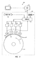
- FIG. 3 is a schematic view of a print drum 310, and a portion of the paper path 126 according to an embodiment of this invention.
- the printheads include printheads 230, 231, 232, and 233 as well as other printheads. All the printheads, which place the ink onto a medium, or paper, form the ink source 140. All the printheads are located within the print zone 128.
- the portion of the paper path 126 includes a media feeder 326, which loads media onto the print drum 310 along the paper load area, depicted by the reference numeral 320 on the area of the drum downstream from the media feeder 326.
- the print drum 310 rotates in a direction depicted by arrow 312
- the print drum 310 and the printing apparatus include several sensors.
- a top of form (“TOF") sensor 340 which is a senses when the incoming media enters the print zone.
- the signal from the TOF sensor 340 feeds a signal back to the controller 242 (shown in FIG. 2).
- the TOF sensor is located upstream of the print zone 128.
- the media load sensor shows that there is paper or a medium 350 on the outer surface of the print drum 310 downstream from the print zone 128.
- the media load sensor 342 indicates that a media is on the outer peripheral surface of the print drum 310.
- the media pick-off sensor 344 senses the presence of the paper. In some instances, the paper or media 320 stays on the print drum for a single pass. In other instances, the paper or media stays on the print drum 310 for multiple passes.
- the media pick-off sensor 344 senses the presence of the paper or media 320 for a single pass or a multiple pass.
- the media pick off sensor inputs this information to the controller 242 (shown in FIG 2).
- the controller 242 enables a media pick-off when the media is to be picked off, or removed, from the surface, or outer peripheral surface of the print drum 310.
- the controller 242 (shown in FIG. 2) moves the media pick-off 360 into position to remove the media from the print drum 310, and specifically from the surface of the print drum 310 (shown in FIGS. 2 and 3).
- the print drum also includes a source of vacuum 365.
- the vacuum 365 produces a vacuum at the peripheral surface of the drum 310.
- a source of radiant heat 370 located within the print drum 310 is a source of radiant heat 370.
- the source of heat 370 is used to dry or partially dry any ink that is laid down or placed on the media 350 which is located on the outer peripheral surface of the print drum 310.
- the media pick-off 360 includes an air jet, or a device which produces a stream of high-pressure, high-volume air which can be directed at the surface of the print drum 310.
- FIG. 4 shows an exploded view of the print drum 310.
- the print drum 310 includes a vacuum drum portion 410, and a screen portion 430.
- the screen portion 430 is dimensioned to fit over an outside or peripheral surface 411 of the drum 410.
- the drum includes a series of channels, such as channel 412 and channel 413, which are circular channels which pass over the outer or peripheral surface of the drum 410.
- the drum also includes longitudinal channels, such as 414 and 415.
- the drum 410 includes openings which occur at the intersections of the circular channels 412, 413 and the longitudinal channels 414, 415. The openings pass through the drum to the vacuum source 365 (as shown in FIG. 3).
- the vacuum 365, and especially the channels 412, 413, 414, 415 and openings 490 distribute the vacuum over the surface of the drum so that media, or paper, such as 350 shown in FIG. 3, are temporarily attached to the drum by the vacuum during the print job.
- the vacuum source 365 acting throughout the channels such as 412, 413, 414, 415 and openings can be maintained so that the media 350 (shown in FIG. 3), stays on print drum 310 for single or multiple passes through the print zone 128 (shown in FIGS. 2 and 3).
- the screen or cover 430 which covers the outer peripheral sur face 411 of the drum 410 serves to distribute heat from the radiant heat source 370.
- the screen 430 is made of a heat-conducting material so that heat from the heat source 370 is distributed substantially evenly over the outside surface of the drum which corresponds to the peripheral surface 431 of the screen 430.
- the screen430 or covering includes a plurality of apertures, such as 432, 433 that are placed over the entire peripheral surface 431 of the covering or screen 430. Each dot shown on the screen 430 represents an aperture.
- the apertures 432, 433 are sufficient to allow the vacuum from the channels 412, 413, 414, 415 to act through the apertures 432, 433.
- the vacuum can then be transferred through the screen or through the covering 430 so that paper or medium 350 (shown in FIGS. 2 and 3) remains on the surface 431 of the screen or covering 430.
- the screen or covering 430 has a sufficient amount of material so that the channels, such as 412, 413, 414, 415 are spanned and heat is distributed substantially evenly over the surface 431 of the screen or covering 430.
- the openings 432, 433 in the screen are small enough so that a substantial amount of material spans the channels 412, 413, 414, 415 associated with the air passageways to prevent uneven heating along the peripheral surface 411 of the print drum 310 between the solid portions and the channels 412, 413, 414, 415.
- the apertures 432, 433 in the screen 430 are also sufficient to allow the pick-off device 360 (shown in FIG. 3) to direct a stream of air toward the surface 431 of the cover or screen 430 and allow air to pass to the surface 411 of the outer drum 410.
- the screen or cover 430 is made of a material which is thermally compatible with the drum 410.
- the screen 430 is made of a material having a coefficient of thermal expansion which is substantially similar to the coefficient of thermal expansion associated with the vacuum drum portion 410 so that thermal mismatches will be either reduced or will not occur.
- the screen material has a coefficient of thermal expansion within the range of 1.0 to 30.0 micrometers/meter/degree Centigrade.
- the screen material has a coefficient of thermal expansion within the range of ten percent less than a coefficient of thermal expansion of the drum material and ten percent greater than the coefficient of thermal expansion of the drum material.
- the cover or screen 430 may be made of the same material as the vacuum drum portion 410. Therefore, the screen 430 and the vacuum drum portion 410 would have the same coefficient of thermal expansion.
- FIG. 5 shows print dum 500 according to another embodiment of this invention.
- the print drum includes a vacuum drum portion 410 which has a screen 530 thereon.
- the vacuum drum portion 410 and the screen 530 are made of materials which have substantially the same coefficient of thermal expansion. This prevents thermal mismatches from occurring when the source of heat or radiant energy within the drum 370 (shown in FIG. 3) heats the vacuum drum portion 410 and the screen 530.
- the screen includes a series of apertures 532, 533 that extend through an outer surface 531 of the screen 530.
- the apertures 532, 533 in the screen 530 are 0.3 mm in diameter, in one embodiment, although the size and shape of the openings may vary.
- the apertures may be evenly distributed over the screen 530 in the embodiment shown in FIG. 5.
- the amount of material that remains as part of the cover or screen is sufficient to span the channels 412, 413, 414, 415 (shown in FIG. 4) of the vacuum drum portion 410 and to allow heat to be distributed evenly over the surface 531 of the screen 530.
- the openings in the screen 530 also allow for an airstream type pick-off to force air to the surface 411 (shown in FIG. 4) of the vacuum drum portion 410 to effectuate a removal of print medium 350 (shown in FIGS. 2 and 3) from the surface of the screen 531.
- the channel pattern forms a grid over the surface 411 of the print drum 410.
- the width, shape, and depth of the channels may vary, in an example embodiment, the channels have a width of approximately 1 millimeter.
- the openings in the barrel through which the vacuum is drawn which occur at the intersections of channels 412, 413 and grooves 414, 415 are also on 20-25 millimeter centers.
- the material which forms the screen 430, 530 in some embodiments, is 0.3 mm thick.
- Invar is available from Belt Technologies, Inc. at Agawam, Massachusetts. At temperatures typical of some of the example embodiments, Invar has a low, almost negligible, coefficient of thermal expansion.
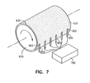
- FIG. 7 is a schematic diagram illustrating a plurality of media ejectors or pick-offs 600 positioned near the surface 631 of a screen 630 of a drum 610 according to an embodiment of the invention.
- Each of the media ejectors or pick-offs 600 is positioned near a circumferential channel of the drum 610 (channels are shown in FIG. 4).
- Each of the media ejectors or pick-offs 600 is in fluid communication with a source of pressurized gas 780, such as air. Any type of pressurized gas may be used, although the example set forth here discusses the use of air.
- FIG. 7 is illustrated without media on the surface 631 of the screen 630 of the drum, for the sake of clarity.
- FIG. 7 is illustrated without media on the surface 631 of the screen 630 of the drum, for the sake of clarity.
- the media ejector or pick-off 600 includes a shovel portion 602 and an air tube or conduit 604.
- the pick-off 600 includes an internal cavity to allow an air tube 604 to pass down the length of the media ejector or pick-off 600 and through the shovel portion 602.
- the air tube or conduit 604 terminates near an end 606 of the pick-off 600 which is near the surface 631 of the screen 630 on the print drum 610.
- the end 606 of the pick-off or media ejector is typically positioned so that the air tube or conduit 604 passing down its length of the pick-off or media ejector 600 directs a stream of air through apertures 632, 633 in the screen 630 and into a channel 612 on the drum 610.
- the pick-off or media ejector 600 is actually positioned near the cover layer 630 and paper is removed from the drum 610 by blowing air into the circumferential channel 612 on the drum 610. The air is directed through the apertures 632, 633 in the screen 630.
- the end 606 of the air tube 604 does not extend into the screen 630. Therefore, the screen also prevents the shovel portion 602 of the meida ejector or pick-off 600 from reaching below a lower surface of the paper 350 held onto the cover 630 of the drum 610.
- the air from the air tube or conduit 604 enters the channel 612 through the apertures 632, 633. Raising the pressure along the channel 612 lifts the paper off the cover 630 upstream from the air tube or conduit 604 of the pick-off 600.
- the pressurization along the channel 612 by the air passing through the air tube or conduit 604 results in an increase in the air pressure within the channel 612 that causes separation of the media 350 from the cover 630 upstream from the shovel portion 602.
- the shovel portion 602 slides below the media 350 so it can then be completely separated from the screen 630 on the drum 610.
- the channel 612 corresponds to one of the air passageways that transmit a vacuum from the drum 610 to the media (see discussion in FIG. 4).
- the source of vacuum is disabled before the media 350 is to be removed from the surface 631 of the screen 630.
- a plurality of media ejection channels separate from the air passageways are pressurized to remove the media 350.
- Some embodiments may allow for separation of a wider range of paper or media weights and may do so in a more gentle, less abrasive way.
- the integrity of the media is maintained which is especially important for duplex printing.
- pressurizing the media from below through a plurality of channels such as 612 avoids touching the freshly printed or inked surface of the media 350.
- using embodiments of this system may result in fewer ink smears on the printed surface of the print medium or paper 350.
- a printing apparatus include a print drum having a peripheral surface.
- the peripheral surface of the print drum has air passageway openings therein.
- a screen is placed over the peripheral surface of the print drum, the screen having openings therein that are smaller than the air passageway openings of the peripheral surface of the print drum.
- the printing apparatus also includes a heat source for heating the peripheral surface of the print drum and the screen. At least a portion of the heat source is located inside the print drum.
- the printing apparatus also includes a vacuum source. The vacuum source is in fluid communication with the air passageway openings on the peripheral surface of the print drum. At least a portion of the vacuum source is inside the print drum.
- the air passageway openings in the print drum include vacuum channels located between the air passageway openings on the peripheral surface of the print drum.
- the heat source heats the peripheral surface of the print drum and the screen, the screen covering the peripheral surface of the drum and passing over the air passageways and the vacuum channels.
- the screen is made of a first material and the peripheral surface of the print drum is made of a second material, and the first material and the second material have a similar coefficient of thermal expansion.
- the screen and the peripheral surface of the print drum are made of a material having the same coefficient of thermal expansion.
- the peripheral surface of the printing apparatus includes a media ejection channel separate from the air passageway openings in the peripheral surface of the print drum, and also includes a source of pressurized gas in fluid communication with the at media ejection channel.
- the media ejection channel and the source of pressurized gas are adapted to produce a force on media greater than the force produced by the vacuum source in fluid communication with the air passageway openings on the peripheral surface of the print drum.
- the source of pressurized gas includes a pressure nozzle directed at the media ejection channel. The pressure nozzle is positioned near the screen so that pressurized gas from the pressure nozzle is directed through the screen and into the media ejection channel.
- a method for printing on media held to a print drum by a vacuum includes placing a screen over the print drum, holding a print medium onto the print drum with a vacuum, depositing ink on the print medium, and heating the print drum and the screen. The method also includes removing the print media from the print drum.
- pressurizing a media ejection channel on the surface of the print drum is part of removing the print media from the print drum. Pressurizing the media ejection channel includes directing a stream of gas into the media ejection channel and through the screen over the print drum. The stream of gas is directed toward the area of the print drum near a leading edge of the media.
- a printing apparatus includes a print drum having a plurality of openings therein, an apparatus for holding media onto the print drum, an apparatus for heating the print drum, and an apparatus for preventing defects on the media due to differences in a heat transfer rate of a surface of the print drum and a heat trans fer rate of the plurality openings in the print drum.
- the apparatus for substantially lessening a set of defects on the media due to differences in a heat transfer rate of a surface of the print drum and a heat transfer rate of the plurality openings in the print drum includes a screen placed on the surface of the print drum, the screen spanning the plurality of openings in the print drum.
- the printing apparatus also includes an apparatus for removing media from the print drum.
- the apparatus for removing media from the print drum includes at least one media ejection channel on a surface of the print drum.
- the at least one media ejection channel is separate from the plurality of openings in the print drum.
- the apparatus for removing media from the print drum includes a nozzle for directing pressurized gas at a surface of the print drum forward of a leading edge of the media on the print drum.
- the apparatus for holding media onto the print drum includes a source of low pressure in fluid communication with the plurality of openings in the print drum and the apparatus for removing media from the print drum, in some embodiments, includes a device for disconnecting the source of low pressure from the plurality of openings in the print drum.
- a printing apparatus has a paper path that includes a source of paper, a print drum having an outside surface having vacuum openings therein for temporarily holding paper onto the print drum as the paper is moved through a print zone.
- the print drum includes a device to substantially lessens defects resulting from the difference between the vacuum openings and the surface of the print drum.
- the paper path also includes a mechanism for moving paper from the source of paper to the print drum, and a device for removing paper from the print drum.
- the printing apparatus also includes a source of ink positioned to deposit ink on the paper when the paper is positioned in the print zone.
- the printing also includes a housing. The paper path and the source of ink are located substantially within the housing.
- the printing apparatus also includes a heat source for heating the print drum.
- a printing apparatus includes a print drum having a peripheral surface, and a nozzle positioned near the peripheral surface of the print drum.
- the nozzle directs a stream of gas toward the print drum and adapted to remove a media carried by the print drum.
- the print drum is substantially cylindrically-shaped and includes an axis. The stream of gas makes an angle traversing a radial line through the axis of the print drum.
Landscapes
- Ink Jet (AREA)
Applications Claiming Priority (2)
| Application Number | Priority Date | Filing Date | Title |
|---|---|---|---|
| US699447 | 1996-08-19 | ||
| US10/699,447 US6983692B2 (en) | 2003-10-31 | 2003-10-31 | Printing apparatus with a drum and screen |
Publications (1)
| Publication Number | Publication Date |
|---|---|
| EP1527893A1 true EP1527893A1 (de) | 2005-05-04 |
Family
ID=34423455
Family Applications (1)
| Application Number | Title | Priority Date | Filing Date |
|---|---|---|---|
| EP04256491A Withdrawn EP1527893A1 (de) | 2003-10-31 | 2004-10-21 | Druckgerät mit Trommel und Maske |
Country Status (2)
| Country | Link |
|---|---|
| US (1) | US6983692B2 (de) |
| EP (1) | EP1527893A1 (de) |
Cited By (2)
| Publication number | Priority date | Publication date | Assignee | Title |
|---|---|---|---|---|
| EP3028863A1 (de) * | 2014-12-02 | 2016-06-08 | OCE-Technologies B.V. | Bogenverarbeitungsvorrichtung mit drehtrommel |
| EP3100867A1 (de) * | 2015-06-05 | 2016-12-07 | Komori Corporation | Druckmaschine |
Families Citing this family (39)
| Publication number | Priority date | Publication date | Assignee | Title |
|---|---|---|---|---|
| US7718029B2 (en) * | 2006-08-01 | 2010-05-18 | Applied Materials, Inc. | Self-passivating plasma resistant material for joining chamber components |
| US7963224B2 (en) * | 2007-03-23 | 2011-06-21 | Hewlett-Packard Development Company, L.P. | Drum having a polymer layer with channels on a metal cylinder |
| US9427994B2 (en) * | 2007-04-26 | 2016-08-30 | Hewlett-Packard Development Company, L.P. | Apparatus and method of tensioning print media |
| US10632740B2 (en) | 2010-04-23 | 2020-04-28 | Landa Corporation Ltd. | Digital printing process |
| US9199448B2 (en) * | 2011-12-07 | 2015-12-01 | Xerox Corporation | Imaging drum surface emissivity and heat absorption control methods, apparatus, and systems for reduction of imaging drum temperature variation |
| US20130215202A1 (en) * | 2012-02-22 | 2013-08-22 | Kevin David Koller | Helical dryer path for a print substrate web |
| US10642198B2 (en) | 2012-03-05 | 2020-05-05 | Landa Corporation Ltd. | Intermediate transfer members for use with indirect printing systems and protonatable intermediate transfer members for use with indirect printing systems |
| US9643403B2 (en) | 2012-03-05 | 2017-05-09 | Landa Corporation Ltd. | Printing system |
| US9902147B2 (en) | 2012-03-05 | 2018-02-27 | Landa Corporation Ltd. | Digital printing system |
| US10569534B2 (en) | 2012-03-05 | 2020-02-25 | Landa Corporation Ltd. | Digital printing system |
| US9498946B2 (en) | 2012-03-05 | 2016-11-22 | Landa Corporation Ltd. | Apparatus and method for control or monitoring of a printing system |
| CN104271687B (zh) | 2012-03-05 | 2016-11-02 | 兰达公司 | 油墨膜构造 |
| US10434761B2 (en) | 2012-03-05 | 2019-10-08 | Landa Corporation Ltd. | Digital printing process |
| WO2013131751A1 (en) | 2012-03-06 | 2013-09-12 | Oce-Technologies B.V. | Recording substrate treatment apparatus, printing system and method of drying |
| CN109177531B (zh) | 2012-03-15 | 2020-11-27 | 兰达公司 | 打印系统的环形柔性皮带 |
| GB201401173D0 (en) | 2013-09-11 | 2014-03-12 | Landa Corp Ltd | Ink formulations and film constructions thereof |
| KR102589330B1 (ko) * | 2014-09-05 | 2023-10-13 | 뉴 웨이 머신 컴포넌츠, 인코포레이티드 | 기체 베어링, 다공성 매체 진공 롤러 및 다공성 매체 에어 턴 |
| GB2536489B (en) * | 2015-03-20 | 2018-08-29 | Landa Corporation Ltd | Indirect printing system |
| GB2537813A (en) | 2015-04-14 | 2016-11-02 | Landa Corp Ltd | Apparatus for threading an intermediate transfer member of a printing system |
| GB201609463D0 (en) | 2016-05-30 | 2016-07-13 | Landa Labs 2012 Ltd | Method of manufacturing a multi-layer article |
| DE112017002714T5 (de) | 2016-05-30 | 2019-02-28 | Landa Corporation Ltd. | Digitales Druckverfahren |
| IT201700005292A1 (it) * | 2017-01-19 | 2018-07-19 | Durst Phototechnik Ag | Vorrichtung und Verfahren zum Bedrucken von unter thermischer Belastung sich verformenden Folien (tedesco) Dispositivo e metodo per stampare materiali che si deformano sotto stress termico |
| WO2019077489A1 (en) | 2017-10-19 | 2019-04-25 | Landa Corporation Ltd. | FLEXIBLE BELT WITHOUT END FOR A PRINTING SYSTEM |
| JP7225230B2 (ja) | 2017-11-19 | 2023-02-20 | ランダ コーポレイション リミテッド | デジタル印刷システム |
| WO2019102297A1 (en) | 2017-11-27 | 2019-05-31 | Landa Corporation Ltd. | Digital printing system |
| US11707943B2 (en) | 2017-12-06 | 2023-07-25 | Landa Corporation Ltd. | Method and apparatus for digital printing |
| US11679615B2 (en) | 2017-12-07 | 2023-06-20 | Landa Corporation Ltd. | Digital printing process and method |
| JP7087497B2 (ja) * | 2018-03-16 | 2022-06-21 | 株式会社リコー | 記録媒体支持装置および画像形成装置 |
| WO2020003088A1 (en) | 2018-06-26 | 2020-01-02 | Landa Corporation Ltd. | An intermediate transfer member for a digital printing system |
| US10994528B1 (en) | 2018-08-02 | 2021-05-04 | Landa Corporation Ltd. | Digital printing system with flexible intermediate transfer member |
| US12001902B2 (en) | 2018-08-13 | 2024-06-04 | Landa Corporation Ltd. | Correcting distortions in digital printing by implanting dummy pixels in a digital image |
| JP7246496B2 (ja) | 2018-10-08 | 2023-03-27 | ランダ コーポレイション リミテッド | 印刷システムおよび方法に関する摩擦低減手段 |
| WO2020136517A1 (en) | 2018-12-24 | 2020-07-02 | Landa Corporation Ltd. | A digital printing system |
| EP3946953A4 (de) | 2019-03-31 | 2022-12-14 | Landa Corporation Ltd. | Systeme und verfahren zur verhinderung oder minimierung von druckdefekten in druckverfahren |
| CN114746813A (zh) | 2019-11-25 | 2022-07-12 | 兰达公司 | 在数字印刷中使用红外辐射来干燥油墨 |
| US11321028B2 (en) | 2019-12-11 | 2022-05-03 | Landa Corporation Ltd. | Correcting registration errors in digital printing |
| EP4081866A4 (de) | 2019-12-29 | 2024-01-03 | Landa Corporation Ltd. | Druckverfahren und -system |
| EP4264377A4 (de) | 2021-02-02 | 2024-11-13 | Landa Corporation Ltd. | Abschwächung von verzerrungen in druckbildern |
| US11667452B2 (en) * | 2021-08-25 | 2023-06-06 | Jack B. Robinson, Jr. | Edge protector |
Citations (2)
| Publication number | Priority date | Publication date | Assignee | Title |
|---|---|---|---|---|
| US6074056A (en) * | 1997-01-22 | 2000-06-13 | Toshiba Tec Kabushiki Kaisha | Ink-jet printer which securely holds a printing medium without contaminating a peripheral surface of a rotary drum |
| US6357869B1 (en) * | 1999-04-14 | 2002-03-19 | Hewlett-Packard Company | Print media vacuum holddown |
Family Cites Families (20)
| Publication number | Priority date | Publication date | Assignee | Title |
|---|---|---|---|---|
| DE2509680A1 (de) * | 1975-03-06 | 1976-09-16 | Hoechst Ag | Verfahren und vorrichtung zum kontinuierlichen farbigen bedrucken von flaechenhaften gebilden in bahnform |
| US4856428A (en) * | 1986-11-07 | 1989-08-15 | American Screen Printing Equipment Company | Extruded print cylinder |
| DE68917612T2 (de) * | 1988-02-09 | 1995-01-12 | Canon Kk | Bildfixiergerät. |
| US4998658A (en) * | 1988-12-27 | 1991-03-12 | Eastman Kodak Company | Drilled unported vacuum drum with a porous sleeve |
| US5137758A (en) * | 1991-03-27 | 1992-08-11 | Minnesota Mining And Manufacturing Company | Apparatus and method for coating flexible sheets while inhibiting curl |
| JPH08183166A (ja) | 1994-12-28 | 1996-07-16 | Riso Kagaku Corp | 輪転式孔版印刷機の印刷用紙始端装着装置 |
| US5555543A (en) * | 1995-01-03 | 1996-09-10 | International Business Machines Corporation | Crossbar switch apparatus and protocol |
| JPH08230261A (ja) * | 1995-02-24 | 1996-09-10 | Fuji Photo Film Co Ltd | シート材吸着ドラム及びこれを用いたカラープルーフ作製方法 |
| DE69720205T2 (de) * | 1996-12-18 | 2003-09-25 | Toshiba Tec K.K., Tokio/Tokyo | Tintenstrahldrucker |
| AU8990598A (en) * | 1997-09-04 | 1999-03-22 | Xaar Technology Limited | Vacuum drums for printing, and duplex printers |
| DE19845214A1 (de) * | 1998-10-01 | 2000-04-06 | Heidelberger Druckmasch Ag | Druckmaschinenzylinder, insbesondere Gegendruckzylinder für eine Bogenrotationsmaschine |
| JP2000128381A (ja) * | 1998-10-27 | 2000-05-09 | Toshiba Tec Corp | 媒体後端引抜排出機構 |
| US6135585A (en) * | 1999-01-08 | 2000-10-24 | Hewlett-Packard Company | Replaceable capping system for inkjet printheads |
| US6299301B1 (en) * | 1999-09-30 | 2001-10-09 | Eastman Kodak Company | Color proofing apparatus and method for writing inkjet images to an intermediate ink receiving element |
| US6174045B1 (en) * | 1999-10-29 | 2001-01-16 | Eastman Kodak Company | Method and apparatus for printing color images using an inkjet printhead and a laser thermal printhead |
| US6328411B1 (en) * | 1999-10-29 | 2001-12-11 | Hewlett-Packard Company | Ferro-fluidic inkjet printhead sealing and spitting system |
| US6313859B1 (en) * | 2000-05-16 | 2001-11-06 | Eastman Kodak Company | Method and apparatus for axial direction sheet feed to a vacuum drum |
| US6513897B2 (en) * | 2000-12-29 | 2003-02-04 | 3M Innovative Properties Co. | Multiple resolution fluid applicator and method |
| US6595615B2 (en) * | 2001-01-02 | 2003-07-22 | 3M Innovative Properties Company | Method and apparatus for selection of inkjet printing parameters |
| US20020130909A1 (en) * | 2001-03-19 | 2002-09-19 | Eastman Kodak Company | Inkjet printing system with internal drum paper feed |
-
2003
- 2003-10-31 US US10/699,447 patent/US6983692B2/en not_active Expired - Lifetime
-
2004
- 2004-10-21 EP EP04256491A patent/EP1527893A1/de not_active Withdrawn
Patent Citations (2)
| Publication number | Priority date | Publication date | Assignee | Title |
|---|---|---|---|---|
| US6074056A (en) * | 1997-01-22 | 2000-06-13 | Toshiba Tec Kabushiki Kaisha | Ink-jet printer which securely holds a printing medium without contaminating a peripheral surface of a rotary drum |
| US6357869B1 (en) * | 1999-04-14 | 2002-03-19 | Hewlett-Packard Company | Print media vacuum holddown |
Cited By (5)
| Publication number | Priority date | Publication date | Assignee | Title |
|---|---|---|---|---|
| EP3028863A1 (de) * | 2014-12-02 | 2016-06-08 | OCE-Technologies B.V. | Bogenverarbeitungsvorrichtung mit drehtrommel |
| US9546070B2 (en) | 2014-12-02 | 2017-01-17 | Océ-Technologies B.V. | Sheet handling apparatus with rotary drum |
| EP3100867A1 (de) * | 2015-06-05 | 2016-12-07 | Komori Corporation | Druckmaschine |
| CN106240156A (zh) * | 2015-06-05 | 2016-12-21 | 小森公司 | 印刷机 |
| US10252547B2 (en) | 2015-06-05 | 2019-04-09 | Komori Corporation | Printing press |
Also Published As
| Publication number | Publication date |
|---|---|
| US6983692B2 (en) | 2006-01-10 |
| US20050092200A1 (en) | 2005-05-05 |
Similar Documents
| Publication | Publication Date | Title |
|---|---|---|
| US6983692B2 (en) | Printing apparatus with a drum and screen | |
| JP5260456B2 (ja) | 画像記録装置 | |
| JP2011180196A (ja) | 画像形成装置 | |
| JP2004216653A (ja) | インクジェット式プリンタ | |
| CN110092220A (zh) | 打印设备和控制方法 | |
| JP2011126131A (ja) | 画像形成装置及び画像形成方法 | |
| JP2002154200A (ja) | 画像形成装置 | |
| JP5306175B2 (ja) | 記録媒体搬送方法及び装置並びに画像形成装置 | |
| JP6705136B2 (ja) | 印刷装置、及び印刷装置の制御方法 | |
| JP2012045770A (ja) | 記録装置 | |
| JP2011201676A (ja) | 印刷装置および印刷物処理装置 | |
| JP2012143874A (ja) | インクジェット記録装置 | |
| JP2003154710A (ja) | 印刷装置 | |
| JP5276558B2 (ja) | 画像形成装置 | |
| JP2023012723A (ja) | 印刷装置 | |
| JP2013086457A (ja) | プリント装置及びシートの乾燥装置 | |
| US10112410B2 (en) | Ink jet printing apparatus and color conversion processing device | |
| CN114179512B (zh) | 记录装置 | |
| JP2001341294A (ja) | 画像記録方法及び装置 | |
| KR20080108978A (ko) | 화상 형성기용 건조 시스템 | |
| US12447745B2 (en) | Method for preserving ink viscosity in inkjets in an inkjet printer during printing | |
| JPH10157222A (ja) | インクジェットプリンタ | |
| JP3774958B2 (ja) | インクジェット記録装置 | |
| JP2021183408A (ja) | 記録装置 | |
| US20240100825A1 (en) | System and method for improving image quality by orienting adjacent printheads to produce opposite direction ink flows in the manifolds of the adjacent printheads |
Legal Events
| Date | Code | Title | Description |
|---|---|---|---|
| PUAI | Public reference made under article 153(3) epc to a published international application that has entered the european phase |
Free format text: ORIGINAL CODE: 0009012 |
|
| AK | Designated contracting states |
Kind code of ref document: A1 Designated state(s): AT BE BG CH CY CZ DE DK EE ES FI FR GB GR HU IE IT LI LU MC NL PL PT RO SE SI SK TR |
|
| AX | Request for extension of the european patent |
Extension state: AL HR LT LV MK |
|
| 17P | Request for examination filed |
Effective date: 20051013 |
|
| AKX | Designation fees paid |
Designated state(s): DE FR GB |
|
| 17Q | First examination report despatched |
Effective date: 20080222 |
|
| STAA | Information on the status of an ep patent application or granted ep patent |
Free format text: STATUS: THE APPLICATION IS DEEMED TO BE WITHDRAWN |
|
| 18D | Application deemed to be withdrawn |
Effective date: 20110222 |