EP1527688A2 - Horizontale Knetmaschine für essbaren Teig, insbesondere für im Ofen gebackene Produkten - Google Patents
Horizontale Knetmaschine für essbaren Teig, insbesondere für im Ofen gebackene Produkten Download PDFInfo
- Publication number
- EP1527688A2 EP1527688A2 EP04023460A EP04023460A EP1527688A2 EP 1527688 A2 EP1527688 A2 EP 1527688A2 EP 04023460 A EP04023460 A EP 04023460A EP 04023460 A EP04023460 A EP 04023460A EP 1527688 A2 EP1527688 A2 EP 1527688A2
- Authority
- EP
- European Patent Office
- Prior art keywords
- kneading
- tank
- kneading machine
- rotation
- machine
- Prior art date
- Legal status (The legal status is an assumption and is not a legal conclusion. Google has not performed a legal analysis and makes no representation as to the accuracy of the status listed.)
- Granted
Links
Images



Classifications
-
- A—HUMAN NECESSITIES
- A21—BAKING; EDIBLE DOUGHS
- A21C—MACHINES OR EQUIPMENT FOR MAKING OR PROCESSING DOUGHS; HANDLING BAKED ARTICLES MADE FROM DOUGH
- A21C1/00—Mixing or kneading machines for the preparation of dough
- A21C1/14—Structural elements of mixing or kneading machines; Parts; Accessories
- A21C1/1405—Tools
-
- A—HUMAN NECESSITIES
- A21—BAKING; EDIBLE DOUGHS
- A21C—MACHINES OR EQUIPMENT FOR MAKING OR PROCESSING DOUGHS; HANDLING BAKED ARTICLES MADE FROM DOUGH
- A21C1/00—Mixing or kneading machines for the preparation of dough
- A21C1/06—Mixing or kneading machines for the preparation of dough with horizontally-mounted mixing or kneading tools; Worm or screw mixers
-
- A—HUMAN NECESSITIES
- A21—BAKING; EDIBLE DOUGHS
- A21C—MACHINES OR EQUIPMENT FOR MAKING OR PROCESSING DOUGHS; HANDLING BAKED ARTICLES MADE FROM DOUGH
- A21C1/00—Mixing or kneading machines for the preparation of dough
- A21C1/14—Structural elements of mixing or kneading machines; Parts; Accessories
- A21C1/1495—Arrangements for cooling or heating ; Arrangements for applying super- or sub-atmospheric pressure
-
- B—PERFORMING OPERATIONS; TRANSPORTING
- B01—PHYSICAL OR CHEMICAL PROCESSES OR APPARATUS IN GENERAL
- B01F—MIXING, e.g. DISSOLVING, EMULSIFYING OR DISPERSING
- B01F27/00—Mixers with rotary stirring devices in fixed receptacles; Kneaders
- B01F27/60—Mixers with rotary stirring devices in fixed receptacles; Kneaders with stirrers rotating about a horizontal or inclined axis
- B01F27/70—Mixers with rotary stirring devices in fixed receptacles; Kneaders with stirrers rotating about a horizontal or inclined axis with paddles, blades or arms
- B01F27/701—Mixers with rotary stirring devices in fixed receptacles; Kneaders with stirrers rotating about a horizontal or inclined axis with paddles, blades or arms comprising two or more shafts, e.g. in consecutive mixing chambers
- B01F27/706—Mixers with rotary stirring devices in fixed receptacles; Kneaders with stirrers rotating about a horizontal or inclined axis with paddles, blades or arms comprising two or more shafts, e.g. in consecutive mixing chambers with all the shafts in the same receptacle
-
- B—PERFORMING OPERATIONS; TRANSPORTING
- B01—PHYSICAL OR CHEMICAL PROCESSES OR APPARATUS IN GENERAL
- B01F—MIXING, e.g. DISSOLVING, EMULSIFYING OR DISPERSING
- B01F35/00—Accessories for mixers; Auxiliary operations or auxiliary devices; Parts or details of general application
- B01F35/75—Discharge mechanisms
-
- B—PERFORMING OPERATIONS; TRANSPORTING
- B01—PHYSICAL OR CHEMICAL PROCESSES OR APPARATUS IN GENERAL
- B01F—MIXING, e.g. DISSOLVING, EMULSIFYING OR DISPERSING
- B01F35/00—Accessories for mixers; Auxiliary operations or auxiliary devices; Parts or details of general application
- B01F35/75—Discharge mechanisms
- B01F35/754—Discharge mechanisms characterised by the means for discharging the components from the mixer
- B01F35/7548—Discharge mechanisms characterised by the means for discharging the components from the mixer using tilting or pivoting means for emptying the mixing receptacle
-
- B—PERFORMING OPERATIONS; TRANSPORTING
- B01—PHYSICAL OR CHEMICAL PROCESSES OR APPARATUS IN GENERAL
- B01F—MIXING, e.g. DISSOLVING, EMULSIFYING OR DISPERSING
- B01F35/00—Accessories for mixers; Auxiliary operations or auxiliary devices; Parts or details of general application
- B01F35/90—Heating or cooling systems
- B01F35/92—Heating or cooling systems for heating the outside of the receptacle, e.g. heated jackets or burners
-
- B—PERFORMING OPERATIONS; TRANSPORTING
- B01—PHYSICAL OR CHEMICAL PROCESSES OR APPARATUS IN GENERAL
- B01F—MIXING, e.g. DISSOLVING, EMULSIFYING OR DISPERSING
- B01F35/00—Accessories for mixers; Auxiliary operations or auxiliary devices; Parts or details of general application
- B01F35/90—Heating or cooling systems
- B01F2035/98—Cooling
-
- B—PERFORMING OPERATIONS; TRANSPORTING
- B01—PHYSICAL OR CHEMICAL PROCESSES OR APPARATUS IN GENERAL
- B01F—MIXING, e.g. DISSOLVING, EMULSIFYING OR DISPERSING
- B01F27/00—Mixers with rotary stirring devices in fixed receptacles; Kneaders
- B01F27/05—Stirrers
- B01F27/07—Stirrers characterised by their mounting on the shaft
- B01F27/072—Stirrers characterised by their mounting on the shaft characterised by the disposition of the stirrers with respect to the rotating axis
- B01F27/0721—Stirrers characterised by their mounting on the shaft characterised by the disposition of the stirrers with respect to the rotating axis parallel with respect to the rotating axis
-
- B—PERFORMING OPERATIONS; TRANSPORTING
- B01—PHYSICAL OR CHEMICAL PROCESSES OR APPARATUS IN GENERAL
- B01F—MIXING, e.g. DISSOLVING, EMULSIFYING OR DISPERSING
- B01F27/00—Mixers with rotary stirring devices in fixed receptacles; Kneaders
- B01F27/05—Stirrers
- B01F27/07—Stirrers characterised by their mounting on the shaft
- B01F27/072—Stirrers characterised by their mounting on the shaft characterised by the disposition of the stirrers with respect to the rotating axis
- B01F27/0723—Stirrers characterised by their mounting on the shaft characterised by the disposition of the stirrers with respect to the rotating axis oblique with respect to the rotating axis
-
- B—PERFORMING OPERATIONS; TRANSPORTING
- B01—PHYSICAL OR CHEMICAL PROCESSES OR APPARATUS IN GENERAL
- B01F—MIXING, e.g. DISSOLVING, EMULSIFYING OR DISPERSING
- B01F27/00—Mixers with rotary stirring devices in fixed receptacles; Kneaders
- B01F27/05—Stirrers
- B01F27/09—Stirrers characterised by the mounting of the stirrers with respect to the receptacle
- B01F27/091—Stirrers characterised by the mounting of the stirrers with respect to the receptacle with elements co-operating with receptacle wall or bottom, e.g. for scraping the receptacle wall
Definitions
- the present invention relates to kneading machines for edible doughs, particularly for oven-baked products, of the type comprising a tank, and at least two kneading tools rotatable within the tank around two substantially horizontal and parallel axes.
- Kneading machines having the above characteristics are also defined simply "horizontal kneading machines". Examples of machines of this kind are illustrated in the documents US-A-4 883 361, US-A-2 050 654, US-A-4 269 582. Such known devices use two counter-rotating kneading tools and typically work according to a continuous process.
- One of the objects of the present invention is to provide a horizontal kneading machine, able to be designed and built instead of as a "continuous" machine also, if desired, as a machine operating in batches, i.e. with a tank that is filled every time with the ingredients needed to obtain a determined quantity of mixture and which is emptied once the mixture is obtained, to allow working a new batch of mixture.
- Another object of the present invention is to provide a horizontal kneading machine that is able to obtain a high quality mixture in a relatively short time.
- the correct execution of the mixture is a critical problem, having to meet a multiplicity of needs.
- On the quality of the mixture depends to a considerable extent the very quality of the oven-baked products obtained by cooking the dough. It is wholly evident that it is necessary for the kneading action to take place in consistent fashion throughout the mixture mass.
- the kneading work is resolved in a transfer of corresponding energy to the mass of the dough, with a consequent rise in its temperature.
- the dough it is beneficial for the dough to be "cut", i.e. divided by the kneading tools, during the kneading operation, because this action is important to activate the enzymatic reactions of the dough.
- this cutting action must not be obtained with a high speed of the kneading tools, which would entail an unacceptable increase in the kneading work and excessive stressing of the mixture mass.
- an additional object of the invention is to provide a horizontal kneading machine of the type set out above which gives rise to an action of cutting the mixture mass during the kneading operation, in order to allow an optimal development of the mixture, providing for contact with the atmosphere of ample surfaces of the mixture mass and further causing an action of stretching and opening the mixture which increases its oxygenation.
- the invention relates to a kneading machine comprising a tank and at least two kneading tools rotatable within the tank around two substantially horizontal axes, characterised in that:
- the orbital movements of said arms around the respective axes of rotation are mutually synchronised, in such a way that the arms pass substantially simultaneously in the area of tangency of their theoretical cylinders, crossing each other with opposite directions of motion, because of the concurrent rotation of the two tools.
- the kneading machine according to the invention is able to produce a mixture of excellent quality. This is due in particular to the cutting action whereto the mixture is subjected every time the two arms of the kneading tools pass in the tangency area of the respective theoretical cylinders, crossing each other with opposite directions of motion.
- the present invention essentially consists of the idea of applying the specific shape and mutual arrangement of the two kneading tools which was the subject of the previous European patent application identified above to a horizontal kneading machine, in order to obtain in combination, the advantages linked to obtaining the cutting effect described above with the specific advantages of a horizontal kneading machine. It should be noted in particular that the aforesaid application results in a horizontal kneading machine of new conception, having two kneading tools, both rotatable in the same direction, which are capable of operating both in a machine working in batches, and in a continuously working machine.
- the kneading tank will preferably be provided with means for emptying it.
- the tank will have elongated conformation, with one end that receives the ingredients of the mixture, or a pre-mixed product, and the opposite end with an outlet wherefrom a continuous loaf of mixture is emitted.
- the advance of the mixture along the tank is obtained not by effect of the kneading tools, but simply by effect of the thrust exerted by the new product which presses at the inlet of the machine.
- the reference number 1 globally designates a horizontal kneading machine, comprising a fixed support structure 2 which in the illustrated example includes a base 3 surmounted by a frame including columns 4 superiorly connected by cross members 5, 6.
- the fixed structure 2 supports a tank 7 for the mixture having a bottom wall 7a (which in the illustrated example is planar), the two longitudinal lateral walls 7B, planar and vertical, and two end walls 7C which are also planar and vertical and arranged in planes that are orthogonal to the planes of the longitudinal walls 7B.
- a bottom wall 7a which in the illustrated example is planar
- the two longitudinal lateral walls 7B planar and vertical
- two end walls 7C which are also planar and vertical and arranged in planes that are orthogonal to the planes of the longitudinal walls 7B.
- the shape of the tank illustrated herein is merely an example of embodiment of the invention, said shape also being able to be wholly different from the preferred shape described herein.
- the bottom wall 7A is connected to the two longitudinal walls 7B by means of two curved walls 7D, with substantially circular profile.
- the example of machine illustrated herein refers to the case of a machine destined to operate in batches, i.e. in which the kneading tank is emptied of the kneaded product at the end of the kneading cycle, thereby being readied to receive the product necessary for a new mixture. Consequently, in the illustrated example, the kneading tank is provided with means able to empty it of its content.
- the tank 7 is supported for this purpose on the fixed structure 2 in oscillating fashion around a longitudinal axis 8 and it is therefore movable between a normal operative condition, illustrated in solid lines in Figure 1, and a rotated condition (illustrated with dashed line in Figure 1) in which the product contained in the tank is poured on a conveyor belt 9 which carries the kneaded product towards the discharge of the machine.
- a normal operative condition illustrated in solid lines in Figure 1
- a rotated condition illustrated with dashed line in Figure 1
- any other means for emptying the tank can be provided.
- a command assembly including an electric motor 10 and a reduction set 11 for actuating a shaft 12 which is mounted rotatable on the fixed structure 2 around the axis 8 of tilt of the tank.
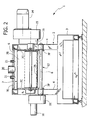
- the structure of the tank is anchored to the shaft 8, by means of flanges 7F ( Figure 2) in such a way that a rotation of the motor 10 causes a consequent oscillation of the tank between its operative position and its tilted position.
- the structure of the tank 7 supports two kneading tools 12 in rotatable fashion around the two horizontal axes 13 positioned symmetrically to the two sides of the longitudinal median plane 14 ( Figure 1) of the tank 7.
- Each of the kneading tools 12 comprises two end disks 12A orthogonal to the respective axis 13 and having hubs mounted rotatable around the axis 13 on the respective end walls 7C of the tank 7.
- each disk is positioned within a recessed cavity of the respective wall 7C, in such was as not to project into the cavity of the wall.
- each kneading tool 12 The two end disks 12A of each kneading tool 12 are mutually joined by a longitudinal arm 12B which in the illustrated example has a substantially quadrangular section and which extends in a rectilinear direction parallel to the horizontal axes of rotation 13.
- the rotation of the two kneading tools 12 is actuated by an electric motor 14 by means of a reduction set 15 and a gearbox 16, shown in section view in Figure 3A.
- the rotation of the output shaft of the gearmotor set 14, 15 is transmitted by a pulley 17 which keyed on said output shaft to two pulleys 19 keyed on end shafts connected to the two kneading tools 12, by means of two belts 18.
- each kneading tools therefore causes an orbital motion of each arm 12B around the respective axis of rotation 13.
- each arm 12B therefore describes a theoretical cylinder 12C with its axis coinciding with the axis of rotation 13.
- the two theoretical cylinders 12C of the two kneading tools are substantially tangential to each other ( Figure 1).
- the two theoretical cylinders 12 are also both tangential to the bottom wall 7A of the tank 7.
- the curved walls 7D can be substantially concentric and immediately adjacent to the two theoretical cylinders 12C of the kneading tools 12.
- a further important characteristic of the invention resides in the fact that the means for actuating the kneading tools are arranged to actuate a synchronised rotation of the two tools 12 in the same direction (see arrows A in Figure 1). Moreover, in the case of the preferred embodiment, the two arms 12B are mutually "in phase” so they reach in substantially simultaneous fashion the area of tangency of the two theoretical cylinders 12C of the kneading tools.
- phase of the two tools 12 can be such that the arms 12B reach the area of tangency of the two theoretical cylinders 12B at non-coinciding, but close times.
- means can be provided for a regulation of the mutual phase of the rotations of the two tools 12.
- the tank 7 is preferably provided with a lid 7E which is provided with manifolds 20, 21 for the introduction of the ingredients needed for the mixture.
- a lid also allows to connect the cavity inside the tank to a source of vacuum or pressure if the mixture is to be obtained in a vacuum or under pressure, according to a known technique.
- Figure 4 shows an embodiment of the tank 7 in which the wall of the tank includes a cooling jacket in which a cooling fluid is made to circulate in order to control the temperature of the kneaded product.
- the distances d1 and d2 of the two theoretical cylinders 12C from the lateral walls 7B are different.
- Figure 5 shows a variant, in which the distances d1 and d2 are substantially identical and the two theoretical cylinders 12C are tangential respectively to the two longitudinal lateral walls 7B.
- Figure 6 schematically shows a plan view of the kneading tank 7, with the two kneading tools 12.
- Figure 7 shows a variant in which each of the arms 12B instead of extending in rectilinear direction along a generatrix of the respective theoretical cylinder 12C, as in Figure 6, extends according to a rectilinear direction inclined relative to the generatrix.
- Figures 8, 9 show two additional variants in which the kneading arms 12B have a broken line profile with two segments inclined in opposite directions. Said positions have the advantage of preserving the progressive effect of the cutting action, characteristic of the solution of Figure 7 without introducing thrusting actions on the dough in the axial direction, since the effects produced by the two differently inclined portions of each arm 12B offset each other.
- the solutions of Figures 8, 9 differ from each other because the aforesaid broken line defines an arrow oriented in the direction of rotation of the tool or in the opposite direction.
- the products needed for the mixture are introduced into the kneading tank through the manifolds 20, 21, whereupon the two kneading tools 12 are set in synchronous and concurrent rotation by means of the motor 14, the reduction unit 15 and the gearbox 16.
- the arrangement of the gearbox 16 described above is provided herein purely by way of example, since for example a gear transmission or any other type of transmission can be provided.
- the mixture is obtained. Every time the two arms 12B cross in correspondence with the area of tangency between the two theoretical cylinders 12C, the dough is "cut" and opened, achieving the benefits discussed above.
- the kneading tools are stopped and the motor 10 is activated to discharge the obtained mixture on the conveyor belt 9.
- the kneading tank would be provided at one end of the tank of a manifold to feed the ingredients of the mixture or a pre-mixed product, and at the opposite end would be provided an outlet for discharging the kneaded mixture, e.g. on a conveyor belt.
- the same thrust exerted by the product entering the tank 7 would produce the advance of the mixture along the tank until it exits at the opposite end. In this way, a continuous loaf of mixture could be obtained at the outlet of the machine.
- each of the arms 12B is preferably quadrangular, but it can naturally also have different conformation.
- the materials suitable for the construction of the kneading tools and of the tank will be chosen by those skilled in the art according to the notions generally known in the field.
- the two kneading tools are made of stainless steel.
- each kneading arm could have a slightly helical profile.
Landscapes
- Chemical & Material Sciences (AREA)
- Chemical Kinetics & Catalysis (AREA)
- Life Sciences & Earth Sciences (AREA)
- Engineering & Computer Science (AREA)
- Food Science & Technology (AREA)
- Manufacturing And Processing Devices For Dough (AREA)
- Mixers Of The Rotary Stirring Type (AREA)
- Food-Manufacturing Devices (AREA)
Applications Claiming Priority (2)
| Application Number | Priority Date | Filing Date | Title |
|---|---|---|---|
| IT000863A ITTO20030863A1 (it) | 2003-11-03 | 2003-11-03 | Macchina impastatrice orizzontale per paste alimentari, particolarmente per prodotti da forno. |
| ITTO20030863 | 2003-11-03 |
Publications (3)
| Publication Number | Publication Date |
|---|---|
| EP1527688A2 true EP1527688A2 (de) | 2005-05-04 |
| EP1527688A3 EP1527688A3 (de) | 2005-11-23 |
| EP1527688B1 EP1527688B1 (de) | 2008-02-20 |
Family
ID=34401333
Family Applications (1)
| Application Number | Title | Priority Date | Filing Date |
|---|---|---|---|
| EP04023460A Expired - Lifetime EP1527688B1 (de) | 2003-11-03 | 2004-10-01 | Horizontale Knetmaschine für essbaren Teig, insbesondere für im Ofen gebackene Produkten |
Country Status (4)
| Country | Link |
|---|---|
| US (1) | US20050111295A1 (de) |
| EP (1) | EP1527688B1 (de) |
| DE (1) | DE602004011873T2 (de) |
| IT (1) | ITTO20030863A1 (de) |
Cited By (6)
| Publication number | Priority date | Publication date | Assignee | Title |
|---|---|---|---|---|
| WO2012037017A3 (en) * | 2010-09-13 | 2012-05-10 | Illinois Tool Works Inc. | Horizontal dough mixer assembley with multi-reduction gear arrangement for bowl tilt |
| EP2722631A4 (de) * | 2011-06-17 | 2015-04-08 | Hrs Invest Ltd | Maschine zum wärmeaustausch mit einem produkt |
| WO2016160441A1 (en) * | 2015-03-30 | 2016-10-06 | Illinois Tool Works Inc. | Canopy and associated seal arrangement for mixer |
| EP3231286A1 (de) * | 2016-03-30 | 2017-10-18 | SANCASSIANO S.p.A. | System zur zubereitung einer mischung |
| US10149482B2 (en) | 2017-03-08 | 2018-12-11 | Illinois Tool Works Inc. | Seal arrangement for horizontal mixer bowl |
| CN109224918A (zh) * | 2018-08-30 | 2019-01-18 | 安徽佳谷豆食品有限公司 | 双轴豆沙搅拌装置 |
Families Citing this family (3)
| Publication number | Priority date | Publication date | Assignee | Title |
|---|---|---|---|---|
| ITTO20021020A1 (it) * | 2002-11-26 | 2004-05-27 | Sancassiano Spa | Macchina impastatrice per paste alimentari particolarmente |
| ATE367197T1 (de) * | 2002-03-05 | 2007-08-15 | Sancassiano Spa | Knetverfahren und knetmaschine für teigmittel, insbesondere für backwaren |
| US7476017B2 (en) * | 2005-09-29 | 2009-01-13 | Jacques Mortimer | Intermeshing kneader with tilting mixing chamber |
Family Cites Families (18)
| Publication number | Priority date | Publication date | Assignee | Title |
|---|---|---|---|---|
| US502392A (en) * | 1893-08-01 | George samuel baker | ||
| US65417A (en) * | 1867-06-04 | John n e a l | ||
| US67964A (en) * | 1867-08-20 | eggebt | ||
| US921361A (en) * | 1906-08-16 | 1909-05-11 | Cyrus Chambers Jr | Dough-mixing machine. |
| US1228550A (en) * | 1916-09-29 | 1917-06-05 | Frank Goger | Mixing and kneading machine. |
| US1447013A (en) * | 1918-12-05 | 1923-02-27 | Graaf Nic H De | Process of making cocoa products |
| US1672264A (en) * | 1926-11-30 | 1928-06-05 | Frank X Lauterbur | Process of mixing dough |
| US2050654A (en) * | 1931-10-15 | 1936-08-11 | Gerstenberg Aage | Apparatus for kneading of margarin and other edible fatty substances |
| GB563813A (en) * | 1943-01-28 | 1944-08-31 | John Edward Pointon | Improvements in and relating to mixing, kneading, shredding, pulping and like machines |
| US4269582A (en) * | 1978-11-21 | 1981-05-26 | Mario Mella | Pasta-making machine |
| DE3146667C2 (de) * | 1981-11-25 | 1984-12-06 | Werner & Pfleiderer, 7000 Stuttgart | Verfahren und Vorrichtung zum Mischen und Dosieren mehrerer Mischgutkomponenten |
| DE8610461U1 (de) * | 1986-04-17 | 1986-06-12 | Loser GmbH & Co, 7500 Karlsruhe | Mehrzweck-Teigbearbeitungsmaschine |
| DE3626732A1 (de) * | 1986-08-07 | 1988-02-11 | Buehler Ag Geb | Conche |
| US4883361A (en) * | 1988-06-09 | 1989-11-28 | B-V Dough Handling Systems, Inc. | Dough processing apparatus |
| DE4100557A1 (de) * | 1991-01-10 | 1992-07-16 | Buehler Ag | Verfahren und vorrichtung zum betrieb einer conche |
| FR2814337B1 (fr) * | 2000-09-28 | 2005-04-22 | Vmi | Petrin horizontal a pales inclinees |
| ATE367197T1 (de) * | 2002-03-05 | 2007-08-15 | Sancassiano Spa | Knetverfahren und knetmaschine für teigmittel, insbesondere für backwaren |
| ITTO20021020A1 (it) * | 2002-11-26 | 2004-05-27 | Sancassiano Spa | Macchina impastatrice per paste alimentari particolarmente |
-
2003
- 2003-11-03 IT IT000863A patent/ITTO20030863A1/it unknown
-
2004
- 2004-10-01 EP EP04023460A patent/EP1527688B1/de not_active Expired - Lifetime
- 2004-10-01 DE DE602004011873T patent/DE602004011873T2/de not_active Expired - Lifetime
- 2004-11-02 US US10/978,467 patent/US20050111295A1/en not_active Abandoned
Cited By (7)
| Publication number | Priority date | Publication date | Assignee | Title |
|---|---|---|---|---|
| WO2012037017A3 (en) * | 2010-09-13 | 2012-05-10 | Illinois Tool Works Inc. | Horizontal dough mixer assembley with multi-reduction gear arrangement for bowl tilt |
| EP2722631A4 (de) * | 2011-06-17 | 2015-04-08 | Hrs Invest Ltd | Maschine zum wärmeaustausch mit einem produkt |
| WO2016160441A1 (en) * | 2015-03-30 | 2016-10-06 | Illinois Tool Works Inc. | Canopy and associated seal arrangement for mixer |
| US10028511B2 (en) | 2015-03-30 | 2018-07-24 | Illinois Tool Works Inc. | Canopy and associated seal arrangement for mixer |
| EP3231286A1 (de) * | 2016-03-30 | 2017-10-18 | SANCASSIANO S.p.A. | System zur zubereitung einer mischung |
| US10149482B2 (en) | 2017-03-08 | 2018-12-11 | Illinois Tool Works Inc. | Seal arrangement for horizontal mixer bowl |
| CN109224918A (zh) * | 2018-08-30 | 2019-01-18 | 安徽佳谷豆食品有限公司 | 双轴豆沙搅拌装置 |
Also Published As
| Publication number | Publication date |
|---|---|
| EP1527688A3 (de) | 2005-11-23 |
| US20050111295A1 (en) | 2005-05-26 |
| DE602004011873D1 (de) | 2008-04-03 |
| DE602004011873T2 (de) | 2009-02-19 |
| EP1527688B1 (de) | 2008-02-20 |
| ITTO20030863A1 (it) | 2005-05-04 |
Similar Documents
| Publication | Publication Date | Title |
|---|---|---|
| EP1527688B1 (de) | Horizontale Knetmaschine für essbaren Teig, insbesondere für im Ofen gebackene Produkten | |
| US5104232A (en) | Vane and chilling systems for tumble mixers | |
| CN111557370B (zh) | 用于制作液体或半液体食品的机器 | |
| RU2281153C2 (ru) | Четырехлопастные невзаимозацепляющиеся роторы смесителя для обеспечения улучшенного рассеивания и распределения при смешивании в закрытом смесителе периодического действия с синхронным электроприводом | |
| EP1550500B1 (de) | Knetverfahren und Knetmaschine für Teigmittel, insbesondere für Backwaren | |
| EP0714606B1 (de) | Knetmaschine für Nahrungsmittel | |
| CN118988038A (zh) | 一种立式高效搅拌装置 | |
| US5482366A (en) | Apparatus for treating dough with a bearingly supported tool carrier | |
| EP2374356B1 (de) | Knetmaschine für Lebensmittel | |
| CN105053116B (zh) | 全自动披萨生产线 | |
| EP1135983B1 (de) | Spiralförmige Knetmaschine mit nichtverdrehbarem Behälter zur Zubereitung von Gemisch auf Mehlbasis | |
| US4883361A (en) | Dough processing apparatus | |
| CN220494111U (zh) | 一种肉类加工用锤揉装置 | |
| KR102253899B1 (ko) | 만두 자동화 성형장치 | |
| SU1512647A1 (ru) | Привод рабочего органа смесител | |
| CN211270273U (zh) | 一种出面率高的面食机 | |
| CN210901158U (zh) | 一种糯米烧卖(麦)成型设备 | |
| RU2035866C1 (ru) | Механизм деформации гибкого рабочего органа вибрационно-волновой машины для производства пищевых продуктов | |
| EP4573908A1 (de) | Teigteilmaschine und verfahren zum teilen eines teigs | |
| EP2550864A2 (de) | Brotteigtrennmaschine | |
| JPS63197526A (ja) | 半径方向混練隙間を有する混練機 | |
| CN219630146U (zh) | 一种中药饮片蜜炙机 | |
| KR102654501B1 (ko) | 중화면용 반죽시트의 제조시스템 | |
| CN120240484A (zh) | 一种自动化便捷式云吞机 | |
| KR200262809Y1 (ko) | 떡볶이용 떡 제조장치 |
Legal Events
| Date | Code | Title | Description |
|---|---|---|---|
| PUAI | Public reference made under article 153(3) epc to a published international application that has entered the european phase |
Free format text: ORIGINAL CODE: 0009012 |
|
| AK | Designated contracting states |
Kind code of ref document: A2 Designated state(s): AT BE BG CH CY CZ DE DK EE ES FI FR GB GR HU IE IT LI LU MC NL PL PT RO SE SI SK TR |
|
| AX | Request for extension of the european patent |
Extension state: AL HR LT LV MK |
|
| PUAL | Search report despatched |
Free format text: ORIGINAL CODE: 0009013 |
|
| AK | Designated contracting states |
Kind code of ref document: A3 Designated state(s): AT BE BG CH CY CZ DE DK EE ES FI FR GB GR HU IE IT LI LU MC NL PL PT RO SE SI SK TR |
|
| AX | Request for extension of the european patent |
Extension state: AL HR LT LV MK |
|
| 17P | Request for examination filed |
Effective date: 20060109 |
|
| AKX | Designation fees paid |
Designated state(s): DE ES FR IT |
|
| GRAP | Despatch of communication of intention to grant a patent |
Free format text: ORIGINAL CODE: EPIDOSNIGR1 |
|
| GRAS | Grant fee paid |
Free format text: ORIGINAL CODE: EPIDOSNIGR3 |
|
| 17Q | First examination report despatched |
Effective date: 20060328 |
|
| GRAA | (expected) grant |
Free format text: ORIGINAL CODE: 0009210 |
|
| AK | Designated contracting states |
Kind code of ref document: B1 Designated state(s): DE ES FR IT |
|
| REF | Corresponds to: |
Ref document number: 602004011873 Country of ref document: DE Date of ref document: 20080403 Kind code of ref document: P |
|
| PG25 | Lapsed in a contracting state [announced via postgrant information from national office to epo] |
Ref country code: ES Free format text: LAPSE BECAUSE OF FAILURE TO SUBMIT A TRANSLATION OF THE DESCRIPTION OR TO PAY THE FEE WITHIN THE PRESCRIBED TIME-LIMIT Effective date: 20080531 |
|
| ET | Fr: translation filed | ||
| PLBE | No opposition filed within time limit |
Free format text: ORIGINAL CODE: 0009261 |
|
| STAA | Information on the status of an ep patent application or granted ep patent |
Free format text: STATUS: NO OPPOSITION FILED WITHIN TIME LIMIT |
|
| 26N | No opposition filed |
Effective date: 20081121 |
|
| PGFP | Annual fee paid to national office [announced via postgrant information from national office to epo] |
Ref country code: FR Payment date: 20101020 Year of fee payment: 7 |
|
| PGFP | Annual fee paid to national office [announced via postgrant information from national office to epo] |
Ref country code: DE Payment date: 20100929 Year of fee payment: 7 |
|
| PGFP | Annual fee paid to national office [announced via postgrant information from national office to epo] |
Ref country code: IT Payment date: 20101005 Year of fee payment: 7 |
|
| REG | Reference to a national code |
Ref country code: FR Ref legal event code: ST Effective date: 20120629 |
|
| PG25 | Lapsed in a contracting state [announced via postgrant information from national office to epo] |
Ref country code: DE Free format text: LAPSE BECAUSE OF NON-PAYMENT OF DUE FEES Effective date: 20120501 |
|
| REG | Reference to a national code |
Ref country code: DE Ref legal event code: R119 Ref document number: 602004011873 Country of ref document: DE Effective date: 20120501 |
|
| PG25 | Lapsed in a contracting state [announced via postgrant information from national office to epo] |
Ref country code: IT Free format text: LAPSE BECAUSE OF NON-PAYMENT OF DUE FEES Effective date: 20111001 Ref country code: FR Free format text: LAPSE BECAUSE OF NON-PAYMENT OF DUE FEES Effective date: 20111102 |