EP1526349A2 - Dispositif pour traiter une bande continue - Google Patents
Dispositif pour traiter une bande continue Download PDFInfo
- Publication number
- EP1526349A2 EP1526349A2 EP04016917A EP04016917A EP1526349A2 EP 1526349 A2 EP1526349 A2 EP 1526349A2 EP 04016917 A EP04016917 A EP 04016917A EP 04016917 A EP04016917 A EP 04016917A EP 1526349 A2 EP1526349 A2 EP 1526349A2
- Authority
- EP
- European Patent Office
- Prior art keywords
- nozzle
- web
- nozzle boxes
- cover
- covering
- Prior art date
- Legal status (The legal status is an assumption and is not a legal conclusion. Google has not performed a legal analysis and makes no representation as to the accuracy of the status listed.)
- Withdrawn
Links
- 239000000969 carrier Substances 0.000 claims abstract description 4
- 238000000605 extraction Methods 0.000 claims description 6
- 230000000873 masking effect Effects 0.000 description 20
- 238000007789 sealing Methods 0.000 description 5
- 239000004744 fabric Substances 0.000 description 3
- 229910000831 Steel Inorganic materials 0.000 description 2
- 239000004760 aramid Substances 0.000 description 2
- 229920006231 aramid fiber Polymers 0.000 description 2
- 239000000835 fiber Substances 0.000 description 2
- 239000003779 heat-resistant material Substances 0.000 description 2
- 239000000463 material Substances 0.000 description 2
- 239000002184 metal Substances 0.000 description 2
- 229920001296 polysiloxane Polymers 0.000 description 2
- 239000010959 steel Substances 0.000 description 2
- 238000004804 winding Methods 0.000 description 2
- 229920003235 aromatic polyamide Polymers 0.000 description 1
- 239000010425 asbestos Substances 0.000 description 1
- 238000007664 blowing Methods 0.000 description 1
- 238000006073 displacement reaction Methods 0.000 description 1
- 238000001035 drying Methods 0.000 description 1
- 230000005489 elastic deformation Effects 0.000 description 1
- 238000007373 indentation Methods 0.000 description 1
- 230000000452 restraining effect Effects 0.000 description 1
- 229910052895 riebeckite Inorganic materials 0.000 description 1
- 229910001220 stainless steel Inorganic materials 0.000 description 1
- 239000010935 stainless steel Substances 0.000 description 1
- 239000004753 textile Substances 0.000 description 1
Images


Classifications
-
- F—MECHANICAL ENGINEERING; LIGHTING; HEATING; WEAPONS; BLASTING
- F26—DRYING
- F26B—DRYING SOLID MATERIALS OR OBJECTS BY REMOVING LIQUID THEREFROM
- F26B13/00—Machines and apparatus for drying fabrics, fibres, yarns, or other materials in long lengths, with progressive movement
- F26B13/10—Arrangements for feeding, heating or supporting materials; Controlling movement, tension or position of materials
- F26B13/108—Arrangements for feeding, heating or supporting materials; Controlling movement, tension or position of materials using one or more blowing devices, e.g. nozzle bar, the effective area of which is adjustable to the width of the material
Definitions
- the invention relates to a device for treating a web according to the Preamble of claim 1.
- Such a device may, for. B. a tension frame dryer for drying and / or Fixing of textile webs be.
- His transporter the tenter, has transport chains, which is guided in mutually adjustable warp rails.
- to Loading the web with treatment gas such as hot air or steam is a Tenter frame dryer with a device with nozzle boxes with on the web directed nozzle openings provided. The nozzle boxes can be above and / or be arranged below the guided in the transport chains web.
- Such Devices are z. As described in DE-U 298 23 493.
- the displaceability of the warp rails allows the use of these devices for different web widths.
- the nozzle boxes for uniform treatment extend the web with treatment gas over the entire width of the web must, they are designed for the maximum web width. Without further action is even at lower web widths treatment gas through the outer, located outside the web nozzle openings on the two sides of the Guided nozzle boxes. Passing treatment gas through this outer Nozzle openings deteriorate the effectiveness of the treatment.
- a nozzle system for. B. nozzle fingers, with a variety of Rows of holes with exhaust openings for blowing a sheet, z. B. one Fabric, with a treatment gas and with a slider with slide holes known.
- the pusher holes are formed so that starting at the ends of the row of holes the outer exhaust ports can be closed in several stages.
- the slider is positioned on the side of the row of holes facing away from the web, d. H. inside a nozzle finger. At the same time the slider is pushed by the pressure of the inflated medium pressed against the row of holes. Sealing problems occur practically not up.
- the disadvantage is that an adjustment of the area covered Exhaust vents, d. H. the nozzle openings formed by the slide Covering only in stages is possible.
- the adjustment of the slide is done manually and requires a considerable amount of operation for adjusting the slide all Nozzle fingers when the web width changes.
- Cover means for the nozzle openings which are adjustable together with the warp rails, are known from DE-C 43 25 301, DE-B 2 029 494 and DE-U 1 871 618.
- DE-C 43 25 301 is a generic device, namely a Tenter frame dryer, described.
- His covering device has a strip-shaped Cover plates formed covering means for covering the nozzle openings in the respective lateral over the web projecting wall portions of its nozzle system.
- Fasteners through which the cover plates are spaced from the chain guide rails, d. H. are arranged to the warp rails, form the driver of the adjusting means.
- the Verstellstoff also have springs through which provided with gaskets Cover plates are pressed against the nozzle boxes of the nozzle system. The outside The nozzle boxes mounted cover plates therefore additionally require these springs and these gaskets.
- the covering means described in DE-U 1 871 681 are via drivers on the chains, namely on the warp rails, connected.
- the nozzles on the nozzle mouth guides on, acting as downwardly directed flanges are formed and corresponding as a cover slide with a C-shaped profile molded cover.
- the guides are characterized by the C-shaped profile of Cover slide covers.
- Space consuming cover devices for the larger inlet and outlet slots are from DE 1 248 002 and US 2 348 174.
- the object of the invention is to provide a device for treating a web according to to develop the preamble of claim 1, the covering means simple and be sealed and allow a continuous coverage of the nozzle openings.
- the covering means have masking strips arranged inside the nozzle boxes are.
- the arrangement inside the nozzle boxes solves the sealing problem, since the effluent treatment gas presses the masking tapes on the bottoms of the nozzle boxes.
- Extending means of the adjusting means act on the cover bands. Through this Extending means the cover surfaces of the cover strips are infinitely variable.
- the Extracting means are connected to the drivers of the adjustment. These also with the Warp-connected drivers are guided separately to the warp rails. you will be when adjusting the warp rails moved along their guides.
- the guides can between the nozzle boxes or outside the nozzle boxes on the of the web be arranged on the opposite side.
- the extraction means according to claim 2 ropes, which on the Attack cover bands, passed through the nozzle boxes and attached to the drivers are. Ropes are with little space requirement, and thereby practically without disturbance of the Flow conditions in the nozzle boxes, through the nozzle boxes feasible.
- return means of the adjusting means are provided for the cover strips, through the extracted by means of Ausziehstoff masking tapes back into their original situation be brought back.
- the masking tapes can be used as one another be formed nestable and extendable plates on both sides, d. H. at the lateral ends, the nozzle boxes are arranged. Return means for such Masking tapes can be attached to the first plates and also to the drivers be connected ropes.
- the masking tapes can also be wound up as waves Be formed bands. Return means for this can be arranged on this shaft Be coil springs that are stretched when unwinding the cover strips.
- the Masking tapes and the return means are made of up to 250 ° C heat-resistant material e.g. made of band steel or aramid fibers.
- the return means may also according to claim 4 return straps, with the Cover strips arranged on common shafts and attached to the drivers are. These return straps are in the opposite direction to the cover bands on the Wrapped in common waves. When the return straps are wound up, the Cover tapes unwound and vice versa.
- the masking tapes according to claim 5 for the two sides of Nozzle boxes with a arranged on one side of the nozzle boxes driver connected.
- the drivers are preferred on the side of Nozzle boxes arranged opposite to the inlet openings of the nozzle boxes are.
- the masking tapes are arranged according to claim 6 of two juxtaposed Nozzle boxes with a arranged in the region between these nozzle boxes driver connected.
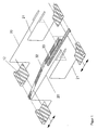
- FIGS. 2 to 9 the principle of the extraction and retraction of the masking tapes shown.
- the first example is shown in FIGS. 2 to 9, the second example in FIGS. 10 and see the third example in Figures 11 and 12.
- Figure 2 shows a cross section through two nozzle boxes with cover strips
- Figure 3 is a longitudinal section
- Figure 4 is a plan view without cover plates of the nozzle boxes
- Figure 5 is a perspective view of both Nozzle boxes with cover strips in a position I for a large web width
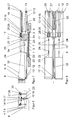
- the Figures 6 to 9 show corresponding representations in a position II for a small Web width.
- FIG. 10 shows the second example with reference to a detail enlargement one of the figure 9 corresponding representation.
- the nozzle boxes are for clarity as shown transparently, which is indicated by dash-dotted lines.
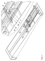
- FIGS. 11 and 12 is the example 2 based on perspective views of two closed Nozzle boxes with cover strips, Figure 11, and an enlarged detail, Figure 12, too see.
- An inventive device for treating a web 1 has a Transport device for the web 1 with transport chains 2 on, in against each other adjustable warp rails 3 are guided. She also has a facility for Actuation of the web 1 with treatment gas on with nozzle boxes 4 with the web 1 directed, symbolized in the drawing by arrows nozzle openings 5 and also symbolized by arrows inlet openings 6 is provided.
- the nozzle boxes 4 are in the transport direction of the web 1 with a specific Distance arranged one behind the other and extend in length perpendicular to Transport direction over the maximum web width. They are above and below the Web 1 is arranged. In the drawings, two nozzle boxes 4 above the Web 1 drawn.
- the nozzle boxes 4 are narrow, with their widths z. B. about 10% of their Lengths amount.
- Each nozzle box 4 has a substantially wedge-shaped housing a floor 7, a ceiling 8, two side walls 9, 10 along its length and one Side wall 11 along its width, wherein the side wall 11 on the Inflow opening 6 opposite side is arranged. On the side of Inlet opening 6 extends this substantially over the entire width and over the entire height of the nozzle box 4.
- the provided with the nozzle openings 5, rectangular bottom 7 is arranged parallel to the web 1.
- In longitudinal section has the Nozzle box 4 the shape of a right triangle, with the right angle between the bottom 7 and the side with the inflow opening 6 is formed.
- the nozzle box 4 tapers along its Length from the inflow opening 6 to the side wall 11.
- the height of the side wall 11th is z. B. 30% of the height of the inflow opening. 6
- the inflow openings 6 of the nozzle boxes 4 do not go from one in the drawing illustrated supply air duct z. As one described in DE-U 298 23 493 Recirculation device off. Such nozzle boxes are also called nozzle fingers.
- the warp rails 3 are located between the upper and lower nozzle boxes 4 and are from a position I ( Figures 3, 4, 5) for a large web width over different Positions in a position II ( Figures 7, 8, 9) for a small web width displaceable.
- the device further comprises a covering device for covering the outside Nozzle openings 5 with cover means and connected to these adjustment means on.
- the adjusting means are provided with carriers connected to the warp beams 3.
- the cover means have cover strips 12, which are arranged in the interior of the nozzle boxes 4 are and their covering surfaces are changed by the driver.
- the Mit vide have the adjusting means extraction means and return means for the cover strips 12, wherein the cover strips 12 are connected via the extraction means with the drivers are.
- the cover strips 12 are formed as thin metal bands, with their rear ends attached to a shaft 13 with a small diameter and on this up and unwound are.
- the shafts 13 are on both sides of the nozzle boxes 4 inside, close to the Side walls 11 and in front of the inlet openings 6 and directly above the floors. 7 arranged.
- the cover strips 12 are not shown in the drawing on the front ends mounts and are guided in the nozzle boxes 4.
- the masking tapes 12 on both sides of a nozzle box 4 are provided with a driver connected, which is arranged on the side wall 11 side.
- the cover strips 12 of two adjacent nozzle boxes 4 are located on a common from the first to second nozzle box 4 through shaft 13. D.h. altogether four masking tapes, the two cover strips 12 of a first nozzle box 4 and the two cover strips 12th an adjacent nozzle box 4 are connected to a driver mentioned.
- the driver is arranged outside the two nozzle boxes 4 and guided separately.
- it has a guided in rails 14 car element 15, a fixed thereto Connecting element 16 for connection to one of the warp rails 3 and also on Carriage element 15 fixed actuator 17.
- the actuator 17, the carriage element 15 and the rails 14 are on the side of the side wall 11 above the nozzle boxes. 4 arranged; d. H. in the area of low height of the nozzle boxes 4.
- the rails 14 are in Area of the gap between the two nozzle boxes 4, in this Example above the gap, arranged. They run horizontally and parallel to the Length of the nozzle boxes 4, perpendicular to the transport direction.
- the carriage member 15 is as a guided in the rails 14, rectangular plate formed at one, in the Drawing lower side of the connecting element 16 and on the other side of the Adjusting element 17 are attached.
- the connecting element 16 is sword-like and protrudes from the carriage member 15, starting perpendicular to this through the gap between the two nozzle boxes 4.
- the connection to the warp rail 3 is through a groove 18 of the connecting element 16 and a corresponding elevation 19 of the warp rail. 3 educated.
- the actuator 17 is formed as a rectangular plate low height. It extends perpendicular to the carriage element 15 parallel to the width of the nozzle boxes 4 via both nozzle boxes 4.
- the extraction means have on the cover strips 12 attacking ropes 20, 21.
- the ropes 20, 21 are guided by means of pulleys 22, 23, 24, 25 through the nozzle boxes 4, about further guide rollers 26, 27 and guided by cable tensioner 28, 29 on the adjusting element 17 of the Driver attached.
- the ropes 20, 21 are at the front ends of the two cover strips 12 on the sides a nozzle box 4 attached.
- the attachment can, not shown in the drawing, by attached to the ropes 20. 21 balls carried out in indentations of front Brackets of the cover strips 12 engage.
- the ropes 20, 21 run in the Inside the nozzle box 4 parallel to the bottom 7 to the middle of the web 1 out are on the deflection rollers 22, 23 deflected by about 90 ° to the ceiling 8 and through the ceiling. 8 guided.
- the pulleys 22, 23 are within the lowest web width, tight over the Floor 7 and the pulleys 24, 25 outside of the nozzle box 4 on the ceiling. 8 arranged, wherein the guide roller 24 to the guide roller 22 slightly in the direction of Stellieris 17 is offset, so that the deflections of the cable 20 to the guide roller 22nd slightly smaller and slightly larger than 90 ° on the pulley 24.
- the distance between the deflection roller 22 and the guide roller 24 is greater than the distance between the Guide roller 23 and the guide roller 25, so that in the example drawn in the drawing the rope 20 is guided over the rope 21.
- the course of the rope 20 about its guide roller 22nd and 24 to the actuator 17 is stepped.
- the course of the rope 21 around his Deflection pulley 23 and 25 is U-shaped.
- This different course of the ropes 20, 21 allows a displacement of both cover strips 12 at the same time by moving the common control element 17.
- the cable tensioner 28, 29 have coil springs. The when mounting slightly tensioned cable tensioner 28, 29 get the tension of the Arrangement of cover strips 12 and ropes 20, 21 upright, whose length is determined by the different winding thickness on the waves 13 when moving the driver something changes.
- the return means have return bands 32, 33 which are on the common shafts 13th are arranged with the cover strips 12.
- the return straps 32, 33 are over a roller 34, a bearing shaft, guided and on the driver, namely on the connecting element 16, attached. They are designed as thin metal bands, with their rear ends on the Attached shaft 13 and on this in the opposite direction to the cover bands 12 up and are unfoldable.
- cover strips 12 of the two nozzle boxes 4 on the side of the inflow opening 6 is the return band 32 and for the two right Masking tapes 12 on the side of the side wall 11, the return tape 33 is provided.
- the Return bands 32, 33 are in the space between the two nozzle boxes.
- the Cover plate leaves in each case to the longitudinal walls 10, 9 of the nozzle boxes 4 a narrow Gap free for the exhaust air.
- the width the return straps 32, 33 corresponds to that of the U-shaped cover plate, wherein the bottom of the U to the web 1 shows and the return bands 32, 33 in the region of the ends of the Nozzle boxes 4 are guided in the legs of the U's.
- the return band 33 of the side of Side wall 11 extends between the nozzle boxes 4 to the middle of the web 1, is on the roller 34 deflected by about 180 ° and fastened to the connecting element 16.
- the Return band 32 of the side of the inflow opening 6 also extends between the Nozzle boxes 4 to the middle of the web 1 out in the example shown in the drawing the roller 34 and the return strap 33 and is fastened to the connecting element 16.
- the cover strips 12, the return bands 32, 33 and the ropes 20, 21 are up to 250 ° C. made of heat-resistant material.
- the masking tapes 12 and the return bands 32, 33 exist z.b. made of spring band steel of a thickness smaller than 0.5 mm. You can also off an aramid fiber or asbestos fiber fabric.
- the width of the masking tapes 12 corresponds to the nozzle boxes 4 or is slightly smaller, the width of the Return straps is 5 to 50 mm.
- the ropes 20, 21 are e.g. Stainless steel - or Aramidmaschineseile. Your diameter can e.g. 1.2 mm. Performances by the Nozzle boxes 4 for the ropes 20, 21 are e.g. sealed by silicone grommets. Instead of the ropes can also be used in different levels movable ball chains also.
- the nozzle boxes 4 shown in the drawing have a flat bottom 7.
- Die Nozzle openings 5 can be formed as slots or as a multiplicity of smaller openings be.
- the Nozzle bottom 7 two V-shaped, extending over the length of the bulges for Web 1 out on, on the legs of a variety of not in the drawing arranged nozzle openings 5 is arranged ( Figure 10).
- the front ends of the Masking tapes 12 with brushes of heat-resistant, not shown in the drawing Material, such as aramid or silicone fibers be provided.
Landscapes
- Engineering & Computer Science (AREA)
- Textile Engineering (AREA)
- Mechanical Engineering (AREA)
- General Engineering & Computer Science (AREA)
- Treatment Of Fiber Materials (AREA)
Applications Claiming Priority (2)
| Application Number | Priority Date | Filing Date | Title |
|---|---|---|---|
| DE10346755 | 2003-10-06 | ||
| DE2003146755 DE10346755B3 (de) | 2003-10-06 | 2003-10-06 | Vorrichtung zum Behandeln einer Warenbahn |
Publications (2)
| Publication Number | Publication Date |
|---|---|
| EP1526349A2 true EP1526349A2 (fr) | 2005-04-27 |
| EP1526349A3 EP1526349A3 (fr) | 2008-11-12 |
Family
ID=34384366
Family Applications (1)
| Application Number | Title | Priority Date | Filing Date |
|---|---|---|---|
| EP04016917A Withdrawn EP1526349A3 (fr) | 2003-10-06 | 2004-07-17 | Dispositif pour traiter une bande continue |
Country Status (2)
| Country | Link |
|---|---|
| EP (1) | EP1526349A3 (fr) |
| DE (1) | DE10346755B3 (fr) |
Cited By (2)
| Publication number | Priority date | Publication date | Assignee | Title |
|---|---|---|---|---|
| ITMI20090128A1 (it) * | 2009-02-03 | 2010-08-04 | Neptun S R L | Macchina asciugatrice a lame d'aria, particolarmente per lastre di vetro e simili. |
| ITFI20130143A1 (it) * | 2013-06-13 | 2014-12-14 | Unitech Textile Machinery Spa | "forno di essicazione per il trattamento di prodotti tessili e metodo di funzionamento di detto forno" |
Families Citing this family (1)
| Publication number | Priority date | Publication date | Assignee | Title |
|---|---|---|---|---|
| DE102005046000A1 (de) | 2004-09-28 | 2006-05-04 | Continental Teves Ag & Co. Ohg | Vorrichtung zum Erfassen eines seitlichen Umfelds eines Fahrzeugs |
Citations (8)
| Publication number | Priority date | Publication date | Assignee | Title |
|---|---|---|---|---|
| US2348174A (en) | 1942-03-28 | 1944-05-02 | B F Sturtevant Co | Drier |
| DE1871681U (de) | 1963-01-21 | 1963-05-09 | Friedel Theben | Sicherheitseinrichtung fuer kunststoffleuchten. |
| DE1871618U (de) | 1963-03-06 | 1963-05-09 | Monforts Fa A | Behandlungsduese mit verstellbarer auslassbreite fuer bahnfoermiges gut. |
| DE1248002B (de) | 1964-11-13 | 1967-08-24 | Krantz H Fa | Schlitzabdeckung an Spannrahmen |
| DE2029494B2 (de) | 1970-06-15 | 1973-06-20 | Bruckner Trockentechnik KG, 7250 Leonberg | Einrichtung zur waermebehandlung einer kontinuierlich bewegten warenbahn |
| DE4331496A1 (de) | 1992-10-07 | 1994-04-14 | Monforts Gmbh & Co A | Düsensystem |
| DE4325301C1 (de) | 1993-07-28 | 1994-10-27 | Babcock Textilmasch | Spannrahmentrockner |
| DE29823493U1 (de) | 1998-06-30 | 1999-07-01 | Babcock Textilmaschinen GmbH, 21220 Seevetal | Umlufttrockner |
Family Cites Families (1)
| Publication number | Priority date | Publication date | Assignee | Title |
|---|---|---|---|---|
| DE19651541A1 (de) * | 1996-12-11 | 1998-06-18 | Brueckner Trockentechnik Gmbh | Spannrahmen |
-
2003
- 2003-10-06 DE DE2003146755 patent/DE10346755B3/de not_active Expired - Fee Related
-
2004
- 2004-07-17 EP EP04016917A patent/EP1526349A3/fr not_active Withdrawn
Patent Citations (8)
| Publication number | Priority date | Publication date | Assignee | Title |
|---|---|---|---|---|
| US2348174A (en) | 1942-03-28 | 1944-05-02 | B F Sturtevant Co | Drier |
| DE1871681U (de) | 1963-01-21 | 1963-05-09 | Friedel Theben | Sicherheitseinrichtung fuer kunststoffleuchten. |
| DE1871618U (de) | 1963-03-06 | 1963-05-09 | Monforts Fa A | Behandlungsduese mit verstellbarer auslassbreite fuer bahnfoermiges gut. |
| DE1248002B (de) | 1964-11-13 | 1967-08-24 | Krantz H Fa | Schlitzabdeckung an Spannrahmen |
| DE2029494B2 (de) | 1970-06-15 | 1973-06-20 | Bruckner Trockentechnik KG, 7250 Leonberg | Einrichtung zur waermebehandlung einer kontinuierlich bewegten warenbahn |
| DE4331496A1 (de) | 1992-10-07 | 1994-04-14 | Monforts Gmbh & Co A | Düsensystem |
| DE4325301C1 (de) | 1993-07-28 | 1994-10-27 | Babcock Textilmasch | Spannrahmentrockner |
| DE29823493U1 (de) | 1998-06-30 | 1999-07-01 | Babcock Textilmaschinen GmbH, 21220 Seevetal | Umlufttrockner |
Cited By (4)
| Publication number | Priority date | Publication date | Assignee | Title |
|---|---|---|---|---|
| ITMI20090128A1 (it) * | 2009-02-03 | 2010-08-04 | Neptun S R L | Macchina asciugatrice a lame d'aria, particolarmente per lastre di vetro e simili. |
| WO2010088975A1 (fr) | 2009-02-03 | 2010-08-12 | Neptun S.R.L. | Séchoir à lame d'air, en particulier pour feuilles de verre et autres |
| ITFI20130143A1 (it) * | 2013-06-13 | 2014-12-14 | Unitech Textile Machinery Spa | "forno di essicazione per il trattamento di prodotti tessili e metodo di funzionamento di detto forno" |
| EP2813791A1 (fr) | 2013-06-13 | 2014-12-17 | Unitech Textile Machinery S.p.a. | Four de séchage pour le traitement de produits textiles et procédé de fonctionnement de ce four |
Also Published As
| Publication number | Publication date |
|---|---|
| DE10346755B3 (de) | 2005-04-28 |
| EP1526349A3 (fr) | 2008-11-12 |
Similar Documents
| Publication | Publication Date | Title |
|---|---|---|
| DE3503909C1 (de) | Simultanbiaxialreckmaschinen fuer thermoplastische Folienbahnen | |
| EP0225429A1 (fr) | Dispositif de transport sans glissement de pièces en position quelconque, notamment en position inclinée ou essentiellement verticale | |
| EP0152576A2 (fr) | Procédé et appareil pour séchage de placages de lame | |
| DE3877883T2 (de) | Filterpresse mit endlosen filterbaendern. | |
| DE69202389T3 (de) | Stauchanlage. | |
| DE2841510C2 (de) | Vorrichtung zum Herstellen einer biaxial verstreckten Folienbahn | |
| DE2533534A1 (de) | Vorrichtung zur waermebehandlung von materialbahnen | |
| EP1526349A2 (fr) | Dispositif pour traiter une bande continue | |
| EP0928757B1 (fr) | Couvercle avec ouverture d'inspection, particulièrment pour convoyeur à bande | |
| CH421487A (de) | Vorrichtung zur Behandlung fortlaufender Folienbahnen mit Randwülsten im gespannten Zustand | |
| DE3835248A1 (de) | Reckvorrichtung | |
| DE3235601C2 (de) | Vorrichtung zur Abdeckung von Warenbahneintritts- und Warenbahnaustrittsschlitzen an Spannrahmen | |
| EP2135986B1 (fr) | Centrale vapeur pour post-traitement de bandes | |
| EP0192207B1 (fr) | Séchoir pour bois de placage | |
| DE202011001750U1 (de) | Vorrichtung zur Reinigung eines Wärmetauschers | |
| DE1729208B2 (de) | Trockner für Furniere, Pappe o.dgl | |
| DE69414646T2 (de) | Vorrichtung zur Trocknung von Warenbahnen, insbesondere Papierbahnen | |
| EP1449958A1 (fr) | Dispositif pour traiter en particulier pour traiter par dépression, la toile de fabrication ou le feutre d'une machine à papier | |
| DE2725356C2 (de) | Vorrichtung zum Festhalten und Bewegen von textilen Bahnen | |
| DE19501953C2 (de) | Vorrichtung zum Absperren eines durch einen als rostartiges Stabwerk ausgebildeten Rechen zum Zurückhalten sperrigen Treibguts geführten Wasserzulaufs zu einer Wasserturbine oder einer Abwasserbehandlungsanlage | |
| DE1248002B (de) | Schlitzabdeckung an Spannrahmen | |
| DE1510710C (de) | Spannvorrichtung fur Unterriemchen an einem Spinnereimaschinen Streckwerk | |
| DE3838618A1 (de) | Abdeckvorrichtung fuer einen warenbahnein- und austrittsschlitz an einem gehaeuse eines spannrahmens | |
| DE1945047A1 (de) | Schrumpftunnel zur Waermebehandlung von mit Schrumpffolie umgebenen Guetern | |
| DE3634188C2 (fr) |
Legal Events
| Date | Code | Title | Description |
|---|---|---|---|
| PUAI | Public reference made under article 153(3) epc to a published international application that has entered the european phase |
Free format text: ORIGINAL CODE: 0009012 |
|
| AK | Designated contracting states |
Kind code of ref document: A2 Designated state(s): AT BE BG CH CY CZ DE DK EE ES FI FR GB GR HU IE IT LI LU MC NL PL PT RO SE SI SK TR |
|
| AX | Request for extension of the european patent |
Extension state: AL HR LT LV MK |
|
| PUAL | Search report despatched |
Free format text: ORIGINAL CODE: 0009013 |
|
| AK | Designated contracting states |
Kind code of ref document: A3 Designated state(s): AT BE BG CH CY CZ DE DK EE ES FI FR GB GR HU IE IT LI LU MC NL PL PT RO SE SI SK TR |
|
| AX | Request for extension of the european patent |
Extension state: AL HR LT LV MK |
|
| STAA | Information on the status of an ep patent application or granted ep patent |
Free format text: STATUS: THE APPLICATION IS DEEMED TO BE WITHDRAWN |
|
| AKX | Designation fees paid | ||
| 18D | Application deemed to be withdrawn |
Effective date: 20090203 |
|
| REG | Reference to a national code |
Ref country code: DE Ref legal event code: 8566 |