EP1526028A2 - Système d'assistance à la conduite pour véhicule - Google Patents
Système d'assistance à la conduite pour véhicule Download PDFInfo
- Publication number
- EP1526028A2 EP1526028A2 EP04024293A EP04024293A EP1526028A2 EP 1526028 A2 EP1526028 A2 EP 1526028A2 EP 04024293 A EP04024293 A EP 04024293A EP 04024293 A EP04024293 A EP 04024293A EP 1526028 A2 EP1526028 A2 EP 1526028A2
- Authority
- EP
- European Patent Office
- Prior art keywords
- reaction force
- obstacle
- risk potential
- vehicle
- calculated
- Prior art date
- Legal status (The legal status is an assumption and is not a legal conclusion. Google has not performed a legal analysis and makes no representation as to the accuracy of the status listed.)
- Granted
Links
- 238000001514 detection method Methods 0.000 claims description 21
- 238000000034 method Methods 0.000 claims description 11
- 230000009467 reduction Effects 0.000 claims description 9
- 230000000979 retarding effect Effects 0.000 claims description 4
- 230000006835 compression Effects 0.000 abstract description 2
- 238000007906 compression Methods 0.000 abstract description 2
- 238000013459 approach Methods 0.000 abstract 1
- 238000012545 processing Methods 0.000 description 17
- 230000001133 acceleration Effects 0.000 description 7
- 230000007246 mechanism Effects 0.000 description 4
- 230000008859 change Effects 0.000 description 3
- 230000003466 anti-cipated effect Effects 0.000 description 2
- 230000007423 decrease Effects 0.000 description 2
- 230000000881 depressing effect Effects 0.000 description 2
- 230000000994 depressogenic effect Effects 0.000 description 2
- 230000000694 effects Effects 0.000 description 2
- 230000005484 gravity Effects 0.000 description 2
- 230000008569 process Effects 0.000 description 2
- 230000009471 action Effects 0.000 description 1
- 230000005540 biological transmission Effects 0.000 description 1
- 230000006870 function Effects 0.000 description 1
- 231100001261 hazardous Toxicity 0.000 description 1
- 238000012986 modification Methods 0.000 description 1
- 230000004048 modification Effects 0.000 description 1
- 230000002093 peripheral effect Effects 0.000 description 1
- 230000004044 response Effects 0.000 description 1
Images


Classifications
-
- B—PERFORMING OPERATIONS; TRANSPORTING
- B60—VEHICLES IN GENERAL
- B60K—ARRANGEMENT OR MOUNTING OF PROPULSION UNITS OR OF TRANSMISSIONS IN VEHICLES; ARRANGEMENT OR MOUNTING OF PLURAL DIVERSE PRIME-MOVERS IN VEHICLES; AUXILIARY DRIVES FOR VEHICLES; INSTRUMENTATION OR DASHBOARDS FOR VEHICLES; ARRANGEMENTS IN CONNECTION WITH COOLING, AIR INTAKE, GAS EXHAUST OR FUEL SUPPLY OF PROPULSION UNITS IN VEHICLES
- B60K31/00—Vehicle fittings, acting on a single sub-unit only, for automatically controlling vehicle speed, i.e. preventing speed from exceeding an arbitrarily established velocity or maintaining speed at a particular velocity, as selected by the vehicle operator
- B60K31/0008—Vehicle fittings, acting on a single sub-unit only, for automatically controlling vehicle speed, i.e. preventing speed from exceeding an arbitrarily established velocity or maintaining speed at a particular velocity, as selected by the vehicle operator including means for detecting potential obstacles in vehicle path
-
- B—PERFORMING OPERATIONS; TRANSPORTING
- B60—VEHICLES IN GENERAL
- B60W—CONJOINT CONTROL OF VEHICLE SUB-UNITS OF DIFFERENT TYPE OR DIFFERENT FUNCTION; CONTROL SYSTEMS SPECIALLY ADAPTED FOR HYBRID VEHICLES; ROAD VEHICLE DRIVE CONTROL SYSTEMS FOR PURPOSES NOT RELATED TO THE CONTROL OF A PARTICULAR SUB-UNIT
- B60W50/00—Details of control systems for road vehicle drive control not related to the control of a particular sub-unit, e.g. process diagnostic or vehicle driver interfaces
- B60W50/08—Interaction between the driver and the control system
- B60W50/14—Means for informing the driver, warning the driver or prompting a driver intervention
- B60W2050/143—Alarm means
-
- B—PERFORMING OPERATIONS; TRANSPORTING
- B60—VEHICLES IN GENERAL
- B60W—CONJOINT CONTROL OF VEHICLE SUB-UNITS OF DIFFERENT TYPE OR DIFFERENT FUNCTION; CONTROL SYSTEMS SPECIALLY ADAPTED FOR HYBRID VEHICLES; ROAD VEHICLE DRIVE CONTROL SYSTEMS FOR PURPOSES NOT RELATED TO THE CONTROL OF A PARTICULAR SUB-UNIT
- B60W2540/00—Input parameters relating to occupants
- B60W2540/12—Brake pedal position
-
- B—PERFORMING OPERATIONS; TRANSPORTING
- B60—VEHICLES IN GENERAL
- B60W—CONJOINT CONTROL OF VEHICLE SUB-UNITS OF DIFFERENT TYPE OR DIFFERENT FUNCTION; CONTROL SYSTEMS SPECIALLY ADAPTED FOR HYBRID VEHICLES; ROAD VEHICLE DRIVE CONTROL SYSTEMS FOR PURPOSES NOT RELATED TO THE CONTROL OF A PARTICULAR SUB-UNIT
- B60W2554/00—Input parameters relating to objects
-
- B—PERFORMING OPERATIONS; TRANSPORTING
- B60—VEHICLES IN GENERAL
- B60W—CONJOINT CONTROL OF VEHICLE SUB-UNITS OF DIFFERENT TYPE OR DIFFERENT FUNCTION; CONTROL SYSTEMS SPECIALLY ADAPTED FOR HYBRID VEHICLES; ROAD VEHICLE DRIVE CONTROL SYSTEMS FOR PURPOSES NOT RELATED TO THE CONTROL OF A PARTICULAR SUB-UNIT
- B60W2710/00—Output or target parameters relating to a particular sub-units
- B60W2710/06—Combustion engines, Gas turbines
- B60W2710/0666—Engine torque
-
- B—PERFORMING OPERATIONS; TRANSPORTING
- B60—VEHICLES IN GENERAL
- B60W—CONJOINT CONTROL OF VEHICLE SUB-UNITS OF DIFFERENT TYPE OR DIFFERENT FUNCTION; CONTROL SYSTEMS SPECIALLY ADAPTED FOR HYBRID VEHICLES; ROAD VEHICLE DRIVE CONTROL SYSTEMS FOR PURPOSES NOT RELATED TO THE CONTROL OF A PARTICULAR SUB-UNIT
- B60W30/00—Purposes of road vehicle drive control systems not related to the control of a particular sub-unit, e.g. of systems using conjoint control of vehicle sub-units
- B60W30/08—Active safety systems predicting or avoiding probable or impending collision or attempting to minimise its consequences
- B60W30/09—Taking automatic action to avoid collision, e.g. braking and steering
Definitions
- the present invention relates to a driving assist system for a subject vehicle, for assisting operations carried out by a driver.
- System for assisting driver's operation include a system disclosed in Japanese Laid-open Patent Publication No. H10-166889. This system changes operation reaction force of an accelerator pedal based on an inter-vehicle distance between a preceding vehicle and a subject vehicle. Warning is given to a driver by increasing reaction force of the acceleration pedal as the distance between vehicles decreases. Further, the system disclosed in Japanese Laid-Open Patent Publication No. H9-286313 sends warnings to a driver by lowering speed in conformance with obstacle information.
- the vehicle driving assist system described above it is therefore desirable for the vehicle driving assist system described above to make a driver aware of risk surrounding a subject vehicle, and also make it possible to control behavior of the subject vehicle taking into consideration the possibility of contact between the subject vehicle and an obstacle.
- a vehicle driving assist system comprising an obstacle detection means (10) for detecting an obstacle in vehicle surroundings; a risk potential calculation means (52) for calculating a risk potential of a subject vehicle with respect to the obstacle based on detection results of the obstacle detection means (10); a drive torque correction means (53, 63) for reducing drive torque generated at the subject vehicle, based on the risk potential calculated by the risk potential calculation means (52); and a reaction force control means (54, 60, 90) for controlling reaction force generated at an operation device through which a travel command for the subject vehicle is issued according to a correction amount for the drive torque to be reduced by the drive torque correction means (53, 63).
- a vehicle driving assist system comprises an obstacle detection means (10) for detecting an obstacle in vehicle surroundings; a risk potential calculationmeans (52) forcalculatingacurrentriskpotential of a subject vehicle with respect to the obstacle based on detection results of the obstacle detection means (10); an accelerator pedal operation amount detection means (64) for detecting an operation amount of an accelerator pedal; a drive torque correction means (53) for correcting a relationship of drive torque with respect to the accelerator pedal operation amount in a reduction direction based on the current risk potential calculated by the risk potential calculation means (52) ; an engine control means (63) for controlling an engine to generate the drive torque calculated by the drive torque correction means (63) ; a reaction force calculation means (54) for calculating a reaction force to be generated at an operation device through which a travel command for the subject vehicle is issued based upon the current risk potential calculated by the risk potential calculation means (52); and a reaction force generation means (60, 90) for generating the reaction force calculated by the reaction force calculation means (54) .
- a vehicle driving assist method an obstacle in vehicle surroundings is detected; a risk potential of a subject vehicle with respect to the obstacle is calculated based on obstacle conditions thus detected; drive torque generated at the subject vehicle is reduced based on the risk potential thus calculated; and reaction force generated at an operation device through which a travel command for the subject vehicle is issued is controlled according to a correction amount for the drive torque to be reduced.
- a vehicle driving assist method an obstacle in vehicle surroundings is detected; a current risk potential of a subject vehicle with respect to the obstacle is calculated based on obstacle conditions thus detected; an operation amount of an accelerator pedal is detected; a relationship of drive torque with respect to the accelerator pedal operation amount is corrected in a reduction direction based on the calculated current risk potential; an engine is controlled to generate the drive torque thus calculated; a reaction force to be generated at an operation device through which a travel command for the subject vehicle is issued is calculated based upon the calculated current risk potential; and the reaction force thus calculated is applied to the operation device.
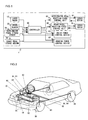
- Fig. 1 is a system drawing showing the structure of a vehicle driving assist system 1 of the first embodiment of the present invention
- Fig. 2 is a structural drawing of a subject vehicle fitted with the vehicle driving assist system 1.
- a laser radar 10 is attached to a front grill section of a subject vehicle or to a bumper etc. , and irradiates infrared light pulses in a horizontal direction so as to scan the region ahead of the subject vehicle.
- the laser radar 10 measures reflected waves of infrared light pulses reflected by a plurality of reflecting objects ahead (normally the rear of a preceding vehicle), and detects a distance from the subject vehicle to each of vehicles to the front and directions of these vehicles relative to the subject vehicle based on the time it takes reflected waves to come back.
- the detected distance between vehicles and directions of the vehicles to the front are output to a controller 50.
- the direction in which a vehicle in front of the subject vehicle exists can be expressed as a relative angle with respect to the subject vehicle.
- Forward regions scanned by the laser radar 10 are about ⁇ 6° each side of a longitudinal centerline of the subject vehicle and forward objects existing within this range are detected.
- a vehicle speed sensor 20 detects a traveling speed of the subject vehicle by measuring rotational speed of wheels or rotational speed of an output shaft of a transmission and outputs the detected vehicle speed to the controller 50.
- the controller 50 includes a CPU and CPU peripheral devices, such as ROM, RAM etc., and performs overall control of the vehicle driving assist system 1.
- the controller 50 determines obstacle conditions or hazardous conditions of the vehicle surroundings, for example, traveling conditions with respect to obstacles such as, for example, a relative distance and relative speed between the subject vehicle and each obstacle based on the subject vehicle speed inputted from the vehicle speed sensor 20 and distance information inputted from the laser radar 10.
- the controller 50 calculates a risk potential of the subject vehicle with respect to each obstacle based on the obstacle conditions. Further, the controller 50 carries out the following control based on the risk potential with respect to obstacles.
- the vehicle driving assist system 1 of the first embodiment of the present invention assists the driver's operation for accelerating or decelerating the subject vehicle, and appropriate assistance is provided for driving operations performed by the driver.
- the controller 50 calculates a degree of reaction force control in a front-to-back direction of the subject vehicle based on the risk potential with respect to the obstacle to the front of the subject vehicle in accordance with the obstacle conditions.
- the controller 50 then outputs the calculated degree of reaction force control in the front-to-back directionto an accelerator pedal reaction force control device 60 and a brake pedal reaction force control device 90.
- the vehicle driving assist system 1 controls drive force and braking force generated at the subject vehicle based on the obstacle conditions for the vehicle surroundings. Specifically, correction amounts for drive force and braking force are calculated according to the risk potential, and are outputted to a drive force control device 63 and a braking force control device 93, respectively.
- the accelerator pedal reaction force control device 60 controls a torque generated by a servo motor 61 incorporated into a link mechanism of the accelerator pedal 62 according to the degree of reaction force control outputted from the controller 50.
- the reaction force to be generated is controlled according to an instruction value from the accelerator pedal reaction force control device 60 and thus, the level of reaction force generated when the driver operates the accelerator pedal 62 can be controlled as desired.
- An accelerator pedal stroke sensor 64 detects operation amount or depression amount of the accelerator pedal 62 converted to a rotation angle of the servo motor 61 via the link mechanism.
- the accelerator pedal stroke sensor 64 outputs the detected operation amount of the acceleration pedal to the controller 50 and the drive force control device 63.
- the brake pedal reaction force control device 90 controls a torque generated by a servo motor 91 incorporated into a link mechanism of the brake pedal 92 according to the degree of reaction force control outputted from the controller 50.
- a reaction force to be generated is controlled according to an instruction value from the brake pedal reaction force control device 90 and thus, the level of the reaction force generated when the driver operates the brake pedal 92 can be controlled as desired.
- the reaction force of the brake pedal is controlled by the servo motor 91
- the present invention is by no means limited in this respect, and, for example, hydraulic force brought about by computer control may also be used to generate brake assist force.
- Abrake pedal stroke sensor 94 detects an operation amount or depression amount of the brake pedal 92 converted to a rotation angle of the servo motor 91 via the link mechanism.
- the brake pedal stroke sensor 94 outputs the detected operation amount of the brake pedal to the controller 50 and the braking force control device 93.
- the drive force control device 63 controls an engine (not shown) in such a manner that drive force is generated according to the operating conditions of the accelerator pedal 62, and changes drive force to be generated according to instructions from outside, i.e. instructions from the controller 50.
- a block view showing the configuration of the drive force control device 63 is shown in FIG. 3.
- a characteristic map defining a relationship between an accelerator pedal operation amount SA and a driver request drive force Fda is shown in FIG. 4.
- the drive force control device 63 includes a driver request drive force calculator 63a, an adder 63b, and an engine controller 63c as shown in FIG. 3.
- the driver request drive force calculator 63a calculates a drive force (driver request drive force) Fda required by the driver according to the operation amount SA (accelerator pedal operation amount) when the accelerator pedal 62 is depressed using the map shown in FIG. 4.
- the adder 63b calculates a target drive force by adding a drive force correction amount ⁇ Da described later to the calculated driver request drive force Fda, and outputs the target drive force to the engine controller 63c.
- the engine controller 63c calculates an engine control instruction value according to the target drive force.
- the engine control instruction value is, for example, an instruction value for controlling a throttle valve position, and the engine controller 63c adjusts a position of a throttle valve in such a manner that the target drive force is implemented.
- the braking force control device 93 controls hydraulic brake pressure in such a manner that braking force is generated according to the operating conditions of the brake pedal 92, and changes hydraulic brake pressure to be generated according to instructions from outside, i.e. instructions from the controller 50.
- a block view showing the configuration of the braking force control device 93 is shown in FIG. 5.
- a characteristic map defining the relationship between a brake pedal operation amount SB and a driver request braking force Fdb is shown in FIG. 6.
- the braking force control device 93 includes a driver request braking force calculator 93a, an adder 93b, and a hydraulic brake pressure controller 93c.
- the driver request braking force calculator 93a calculates a braking force (driver request braking force) Fdb required by the driver according to the depression amount (brake pedal operation amount) SB of the brake pedal 92 using the map shown in FIG. 6.
- the adder 93b calculates a target braking force by adding a brake force correction value ⁇ Db described later to the calculated driver request braking force Fdb, and outputs the target braking force to the hydraulic brake pressure controller 93c.
- the hydraulic brake pressure controller 93c calculates a hydraulic brake pressure instruction value according to the target brake force.
- Brake devices 95 provided at each wheel then operate according to instructions from the hydraulic brake pressure controller 93c .
- FIG. 7 A block view showing the configuration of the inside and periphery of the controller 50 is shown in FIG. 7.
- the controller 50 is constituted of an obstacle recognition unit 51, a risk potential (RP) calculation unit 52, a drive force/braking force correction amount calculation unit 53, and an operation reaction force calculation unit 54 in the form of software in CPU.
- RP risk potential
- the obstacle recognition unit 51 receives signals from the laser radar 10 and the subject vehicle speed sensor 20 and recognizes obstacle conditions in the front region of the subject vehicle. Specifically, the inter-vehicle distance to a preceding vehicle and the relative speed is calculated, and a vehicle speed is detected.
- the risk potential calculation unit 52 calculates a risk potential RP of the subject vehicle with respect to a front obstacle based on recognition results of the obstacle recognition unit 51.
- the drive force/braking force correction amount calculation unit 53 calculates correction amounts of drive force and braking force based on the risk potential RP calculated by the risk potential calculation unit 52.
- the operation reaction force calculation unit 54 calculates a reaction force control instruction value for the accelerator pedal 62 and a reaction force control instruction value for the brake pedal 92 based on the risk potential RP calculated by the risk potential calculation unit 52.
- the controller 50 carries out the reaction force control of the accelerator pedal 62 and brake pedal 92 and drive force/braking force control based on the same risk potential RP calculated at the risk potential calculator 52. Namely, the operation reaction force control and the drive force/braking force control are carried out simultaneously based on the same risk potential.
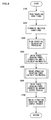
- Fig. 8 shows a flowchart of a processing sequence for a drive operation assist control of the controller 50 of the first embodiment. The content of this processing is carried out continuously at fixed intervals of, for example, 50 msecs.
- traveling conditions are read in in step S100.
- traveling conditions corresponds to information relating to vehicle traveling conditions that include obstacle conditions to the front of the subject vehicle.
- the distance D to a front obstacle and the direction in which that obstacle exists detected by the laser radar 10 and the traveling speed Vh of the subject vehicle detected by the subject vehicle speed sensor 20 are read-in.
- the accelerator pedal operation amount SA and the brake pedal operation amount SB detected by the accelerator pedal stroke sensor 64 and the brake pedal stroke sensor 94 respectively are also read-in.
- step S200 conditions of the front obstacle are recognized based on traveling condition data read in and recognized in step S100.
- the relative position, direction of movement and movement speed of the obstacle with respect to the subject vehicle at this time point are determined using the relative position, direction of movement and movement speed of the obstacle with respect to the subject vehicle stored in memory of the controller 50 detected in the previous processings and the current traveling condition data obtained in step S100.
- the manner in which obstacles are arranged to the front of the subject vehicle with respect to the movement of the subject vehicle and their relative movement etc. are recognized.
- step S300 the risk potential RP with respect to the obstacle is calculated as shown in the following.
- the risk potential RP with respect to an obstacle, i.e. , the preceding vehicle 120 is defined as the extent of compression of the virtual resilient member 110 in the event that the virtual resilient member 110 comes into contact with and is compressed by the preceding vehicle 120 as shown in FIG. 9B.
- D is the distance between the subject vehicle 100 and the preceding vehicle 120
- 1 is the length of the virtual resilient member 110.
- step S400 the correction amounts for the drive force and the braking force are calculated based on the risk potential RP with respect to the obstacle calculated in step S300.
- the correction amounts of the drive force and braking force are defined as the psuedo travel resistance applied to the subject vehicle 100 when the virtual resilient member 110 comes into contact with and is compressed by the preceding vehicle 120. Namely, a restoring force of the virtual resilient member 110 when the inter-vehicle distance D is short and the virtual resilient member 110 is compressed as shown in FIG. 9B is calculated as the correction amounts of the drive force and braking force.
- k is a resilience constant for the virtual resilient member 110 and is a control parameter appropriately adjusted in advance to give appropriate control results.
- the restoring force Fc becomes larger as the risk potential RP with respect to the preceding vehicle becomes higher, i.e. , as the inter-vehicle distance D becomes smaller with respect to the length 1 of the virtual resilient member 110 as shown in (Expression 3).
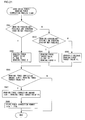
- step S400 a detailed description of the process for calculating the drive force and braking force correction amounts carried out in step S400 is given with reference to the flowchart of FIG. 10.
- step S401 the restoring force Fc of the resilient member provided virtually at the front of the subject vehicle is calculated using (Expression 3) described above.
- step S402 the driver request drive force Fda is estimated.
- a map that is the same as the driver request drive force calculation map shown in FIG. 4 stored in the drive force control device 63 is also stored in the controller 50.
- the controller 50 estimates the driver request drive force Fda according to the accelerator pedal operation amount SA in accordance with the map shown in FIG. 4.
- step S403 the restoring force Fc of the virtual resilient member calculated in step S401 and the driver request drive force Fda calculated in step S402 are compared to each other.
- step S404 is proceeded to.
- -Fc is set as a drive force correction amount ⁇ Da
- step S405, 0 is set as a braking force correction amount ⁇ Db. Namely, because Fda - Fc ⁇ 0 , a positive drive force is still to be generated after correcting the drive force Fda using the restoring force Fc.
- the correction amount can be achieved only by the drive force control device 63.
- the vehicle behavior is in such a state that a drive force of the extent anticipated by the driver is not obtained regardless of the driver depressing the accelerator pedal 62.
- the driver feels that the acceleration has become sluggish.
- the driver feels that the vehicle is decelerating.
- step S406 the drive force correction amount ⁇ D a is set to -Fda, and in step S407, the shortfall in the correction amount (Fc - Fda) is taken to be the braking force correction amount ⁇ D b. In this event, the driver perceives that the vehicle is decelerating.
- FIG. 11 A view illustrating a method of correcting the drive force and the braking force is shown in FIG. 11.
- the horizontal axis of FIG. 11 shows the accelerator pedal operation amount SA and the brake pedal operation amount SB with the accelerator pedal operation amount SA becoming large as advancing from the origin 0 to the right, and the brake pedal operation amount SB becoming large as advancing to the left.
- the vertical axis of FIG. 11 shows the drive force and braking force, and shows drive force becoming larger upon advancement from the origin 0 upwards and shows braking force becoming larger upon advancement downwards.
- the required drive force Fda corresponding to the accelerator pedal operation amount SA and the required braking force Fdb corresponding to the brake pedal operation amount SB are each shown by a one-dot chain line. Further, the drive force and braking force corrected according to the risk potential RP are each shown by a solid line.
- the drive force is corrected in a reduction direction according to the correction amount ⁇ D a .
- the drive force is corrected by setting the correction amount ⁇ Da in such a manner that no drive force is to be generated. Further, the difference between the restoring force Fc and the required drive force Fda is set as the correction amount ⁇ Db.
- a retarding action is carried out according to the accelerator pedal operation amount SA. The retarding action is achieved by applying a gentle braking to slow the vehicle down while the accelerator pedal 62 is still being operated.
- the brake pedal 92 When the brake pedal 92 is pushed down, the braking force is corrected in an increasing direction based on the correction amount ⁇ Db. As a result, the characteristic of the drive force and braking force is corrected in such a manner that the travel resistance applied to the subject vehicle is increased as a whole in accordance with the correction amounts, i.e., the restoring force Fc of the virtual resilient member.
- Step S500 is advanced to after the drive force and braking force correction amounts are calculated in step S400.
- step S500 a reaction force control instruction value FA to be outputted to the accelerator pedal reaction force control device 60 and a reaction force control instruction value FB to be outputted to the brake pedal reaction force control device 90 are calculated based on the risk potential RP with respect to the preceding vehicle. Specifically, the reaction force control instruction values FA and FB corresponding to the drive force correction amount ⁇ Da and the braking force correction amount ⁇ Db calculated in step S400 are calculated respectively so that operation reaction force control is carried out at the same time as the drive force/braking force control.
- step S500 The operation reaction force calculation process of step S500 is described in detail using the flowchart of FIG. 12.
- step S501 the accelerator pedal reaction force control instruction value FA is calculated based on the risk potential RP according to the current obstacle conditions calculated in step S300.
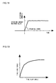
- FIG. 13 shows a relationship between risk potential RP and accelerator pedal reaction force control instruction value FA.
- the accelerator pedal reaction force control instruction value FA is calculated in such a manner that a larger accelerator pedal reaction force is generated for a larger risk potential RP.
- the reaction force control instruction value FA is fixed at a maximum value FAmax to ensure that the maximum accelerator pedal reaction force is generated.
- the reaction force control instruction value FB is calculated based on the risk potential RP.
- FIG. 14 shows a relationship between risk potential RP and brake pedal reaction force control instruction value FB.
- the reaction force control instruction value FB is calculated in such a manner that a smaller brake pedal reaction force, i. e. a larger brake assist force, is generated for a larger risk potential RP.
- the reaction force control instruction value FB is fixed at a predetermined value FBmin to ensure that the minimum brake pedal reaction force is generated.
- the accelerator pedal reaction force characteristics and the brake pedal reaction force characteristics are modified, and the driver is made aware of the magnitude of the current risk potential RP through the accelerator pedal reaction force.
- the accelerator pedal reaction force control instruction value FA is taken as a maximum, and the driver is invited to release the accelerator pedal 62.
- the brake pedal reaction force control instruction value FB is taken as a minimum, and control is exerted so that the brake pedal 92 is easily depressed when the driver's operation is shifted to a braking operation.
- the drive force correction amount ⁇ Da and the braking force correction amount ⁇ Db, and the reaction force control instruction values FA and FB based on the current risk potential RP according to the current obstacle conditions it is possible to simultaneously execute the drive force/braking force correction, accelerator pedal reaction force control and brake pedal reaction force control.
- the braking force correction amounts ⁇ D a and ⁇ Db generated at the subject vehicle at the current time are transmitted to the driver simultaneously as the accelerator pedal operation reaction force or the brake pedal operation reaction force. Because of this, the correction state of the drive force and the braking force of the subj ect vehicle, i. e. the subject vehicle control state can be made known to the driver in an indirect and intuitive manner as operation reaction force of the accelerator pedal 62 or the brake pedal 92 so as to give a sense of security.
- Step S600 is proceeded to after calculating the reaction force control instruction values FA and FB in step S500.
- step S600 the drive force correction amount ⁇ D a and braking force correction amount ⁇ Db calculated in step S400 are outputted to the drive force control device 63 and the braking force control device 93, respectively.
- the drive force control device 63 calculates a target drive force from the drive force correction amount ⁇ D a and the required drive force Fda, and controls the engine controller 63c in such a manner that the calculated target drive force is generated.
- the braking force control device 93 calculates a target braking force from the braking force correction amount ⁇ Db and the required braking force Fdb, and controls the hydraulic brake pressure controller 93c in such a manner that the target brake force is generated.
- step S700 the accelerator pedal reaction force control instruction value FA and the brake pedal reaction force control instruction value FB calculated in step S500 are outputted to the accelerator pedal reaction force control device 60 and the brake pedal reaction force control device 90, respectively.
- the accelerator pedal reaction force control device 60 and the brake pedal reaction force control device 90 control the accelerator pedal reaction force and the brake pedal reaction force according to instruction values inputted from the controller 50.
- the following is a description of a vehicle driving assist system of a second embodiment of the present invention.
- the configuration for the vehicle driving assist system of the second embodiment is the same as for the first embodiment shown in FIG. 1 and FIG. 2. Description here will mainly focus on points of difference from the first embodiment.
- automatic braking control generating braking force automatically is carried out based on the results of the determination as to the possibility of evasion.
- Fig. 15 shows a flowchart of a processing sequence for a drive operation assist control of the controller 50 of the second embodiment.
- the content of this processing is carried out continuously at fixed intervals of, for example, 50 msecs.
- step S100 to step S500 is the same as step S100 to step S500 of the flowchart of FIG. 8 described in the first embodiment and description thereof is therefore omitted.
- step S520 a determination is made as to whether or not the front obstacle can be evaded as a result of steering the subj ect vehicle based on the condition of the front obstacle recognized in step S200.
- a lateral movement distance y which is necessary for the subject vehicle to move in order to avoid the front obstacle is calculated and then a determination is made as to whether or not evasion is possible through steering.
- FIG. 16 The positional relationship between a subject vehicle 200 and a front obstacle or a preceding vehicle 210 is shown in FIG. 16.
- angles of a right end 211 and left end 212 of the preceding vehicle 210 with respect to the longitudinal centerline of the subject vehicle 200 are taken to be ⁇ 1 and ⁇ 2 respectively.
- the preceding vehicle 210 can be avoided to either the right direction of the angle of ⁇ 1 or the left direction of the angle of ⁇ 2, the direction with the smaller angle ⁇ 1 is selected.
- the lateral movement distance y necessary in order to avoid the preceding vehicle 210 through steering the subject vehicle 200 in the direction ⁇ 1 is then calculated.
- the lateral movement distance y can be calculated from the following (Expression 7).
- y D ⁇ sin ( ⁇ 1) + 1 w/2
- D is the distance between the vehicles
- lw is the width of the subject vehicle.
- the direction of the preceding vehicle 210 as shown in FIG. 17 can be detected within a range ⁇ 1 to ⁇ 2 of a certain width.
- the necessary lateral movement distance y for evasion taking the minimum angle ⁇ 1 of the range ⁇ 1 to ⁇ 2 as the direction of the preceding vehicle 210, is calculated using (Expression 7) described above.
- the extent of the offset of the fitting position of the laser radar 10 is appropriately added or subtracted in (Expression 7).
- a time ty necessary for the subject vehicle to move in a lateral direction by the lateral movement distance y necessary to evade the preceding vehicle is calculated.
- the steering characteristics of the subject vehicle can be expressed by (Expression 8) and (Expression 9) in the following.
- ⁇ f is front wheel steering angle. Assuming that at times of emergency the driver steers by a maximum steering amount at a steering speed shown in FIG. 18, a front wheel steering angle ⁇ f is set in accordance with the characteristic shown in FIG. 18.
- Ff and Fr in (Expression 10) and (Expression 11) are functions expressing a side force generated with respect to a tire slip angle, and are defined by the relationship shown in FIG. 19.
- the time ty for lateral movement calculated in this manner is compared with an estimated period of time D/Vr until the subject vehicle and the front obstacle make contact. In the event that the estimated time D/Vr until contact is smaller than the time ty for lateral movement (D/Vr ⁇ ty), it is determined that evasive action through steering is not possible.
- the time ty for evasive steering is calculated taking into consideration differences in the steering characteristics of vehicles, it is possible to reliably calculate whether or not a front obstacle cane be evaded regardless of differences in steering characteristics from vehicle to vehicle and steering characteristics that differ in vehicle speed range. Moreover, as the characteristics of driver's steering operation at the time of emergencies is also take into account in calculating the vehicle steering evasion time ty, it is possible to calculate steering evasion time ty at the time of emergencies in a more accurate manner.
- step S540 is proceeded to.
- step S540 it is determined whether or not evasion is possible by braking. Specifically, it is determined that it is not possible to evade the front obstacle through braking when the distance D between the subject vehicle and the front obstacle and the relative velocity Vr recognized in step S200 meet the following (Expression 13). D ⁇ - Vr ⁇ Td + Vr 2 /2a
- step S560 the drive force correction amount and the braking force correction amount calculated in step S400 are corrected based on the possibility of steering evasion determined in step S520 and the possibility of braking evasion determined in step S540.
- the processing carried out in step S560 is now described using the flowchart in FIG. 21.
- step S561 it is determined whether or not the front obstacle can be evaded by neither braking nor steering.
- step S562 is proceeded to.
- a braking force target value Ft is calculated using a braking force 2 shown in FIG. 22. Specifically, the braking force target value Ft is calculated so as to reach the braking force 2 set in advance at a predetermined inclination as shown in FIG. 22.
- step S563 is proceeded to, and it is determined whether or not evasion of the front obstacle is possible using braking or steering.
- step S564 is proceeded to.
- a braking force target value Ft is calculated using a braking force 1 shown in FIG. 22. Specifically, the braking force 1 smaller than the braking force 2 is calculated as the braking force target value Ft.
- the braking force 1 becomes gradually larger at a fixed inclination of ⁇ .
- the inclination ⁇ of the braking force 1 is calculated such that a difference p1 between the braking force 1 and the braking force 2 is less than a predetermined value when shifting from a state where the braking force 1 is applied to a state where the braking force 2 is applied.
- the inclination ⁇ is calculated in the following manner.
- a time T1 from the start of application of the braking force 1 to when the braking force 2 starts acting is estimated.
- the time T1 can be expressed in the following (Expression 14) using the time for lateral movement ty necessary for evasion by steering.
- T1 D/Vr - ty
- T1 - (D-Vr 2 /2a + Vr ⁇ Td)/Vr
- Td is idle time until the brake starts functioning after the driver's braking operation
- "a" is deceleration generated by the braking operation.
- the inclination ⁇ of the braking force 1 can be calculated from (Expression 16) in the following using the time T1 calculated in the above manner and the difference p1 between the braking force 2 and the braking force 1.
- step S565 is proceeded to.
- the set braking force target value Ft is gradually made smaller at a prescribed gradient until the braking force target value Ft becomes 0.
- Change in time series of the braking force target value Ft is shown in FIG. 23.
- the braking force target value Ft is gradually made larger from 0 in accordance with the braking force 1.
- the braking force target value Ft increases at a prescribed inclination to the braking force 2, and dramatic braking is carried out by shifting from the braking force 1 to the braking force 2.
- step S566 it is determined whether or not the braking force correction amount ⁇ D b calculated in step S400 is smaller than the braking target value Ft calculated in step S562, S564 or S565.
- step S567 is proceeded to.
- step S567 and the braking force target value Ft is set as the braking force correction amount ⁇ D b .
- step S568 in order to put the driving force to 0, a value -Fda corresponding to the accelerator pedal operation amount SA is set as the driving force correction amount ⁇ D a.
- the braking force correction amount ⁇ Db and the driving force correction amount ⁇ Da calculated in step S400 are used as they are.
- step S580 After the drive force correction amount ⁇ Da and braking force correction amount ⁇ D b are corrected in step S560, step S580 is proceeded to.
- step S580 correction of operation reaction force is carried out according to the possibility of steering evasion determined in step S520 and the possibility of braking evasion determined in step S540. This processing is described according to the flowchart shown in FIG. 24.
- step S581 it is determined whether or not the evasion of the front obstacle by steering is not possible and the evasion by braking is also not possible based on the possibility of steering evasion and possibility of braking evasion determined as described above.
- step S582 is proceeded to.
- the accelerator pedal reaction force control instruction value FA is set to the maximum value FAmax so that maximum accelerator pedal reaction force is generated.
- step S583 the brake pedal reaction force control instruction value FBmin is set to the predetermined value FBmin so that the minimum brake pedal reaction force is generated.
- step S581 In the event that a negative determination is made in step S581 is determined to be negative and the front obstacle can be avoided by either steering or braking, the reaction force control instruction values FA and FB calculated in step S500 are used without correction.
- Step S600 is proceeded to after the operation reaction force control instruction values are corrected in step S580.
- the reaction force control instruction values FA and FB corrected in step S580 are outputted to the accelerator pedal reaction force control device 60 and the brake pedal reaction force control device 90 respectively, and accelerator pedal reaction force control and brake pedal reaction force control are carried out.
- the drive force correction amount ⁇ Da and the braking force correction amount ⁇ D b corrected in step S560 are outputted to the drive force control device 63 and the braking force control device 93 respectively, and drive force control and braking force control are carried out. This terminates the processing for this time.
- reaction force control instruction values FA and FB are corrected to predetermined values FAmax and FBmin according to the possibility of evasion of the front obstacle in the processing of step S580. This is, however, by no means limiting, and the reaction force control instruction values FA and FB calculated in step S500 can be used without correction according to the possibility of contact.
- reaction force control and drive force/braking force control is carried out according to current risk potential RP.
- reaction force control and drive force control it is also possible just for reaction force control and drive force control to be carried out.
- reaction force control is carried out according to the risk potential RP, and the drive force correction amount ⁇ D a can be made known to the driver in real time as change in accelerator pedal reaction force or brake pedal reaction force.
- reaction force control and drive force/braking force control is carried out according to the current risk potential RP and automatic braking control is carried out according to the possibility of evasion of a front obstacle.
- the drive force correction amount ⁇ D a is appropriately set so as to reduce the drive force, and when the evasion of the obstacle becomes impossible, the braking force target value Ft is appropriately set so as to increase the braking force.
- both accelerator pedal reaction force control and brake pedal reaction force control are carried out according to the current risk potential RP of the vehicle surroundings. This is, however, by no means limiting, and it is also possible to carry out one of accelerator pedal reaction force control and brake pedal reaction force control.
Landscapes
- Engineering & Computer Science (AREA)
- Chemical & Material Sciences (AREA)
- Combustion & Propulsion (AREA)
- Transportation (AREA)
- Mechanical Engineering (AREA)
- Control Of Driving Devices And Active Controlling Of Vehicle (AREA)
- Regulating Braking Force (AREA)
- Control Of Throttle Valves Provided In The Intake System Or In The Exhaust System (AREA)
- Traffic Control Systems (AREA)
Applications Claiming Priority (2)
| Application Number | Priority Date | Filing Date | Title |
|---|---|---|---|
| JP2003363673 | 2003-10-23 | ||
| JP2003363673A JP4487534B2 (ja) | 2003-10-23 | 2003-10-23 | 車両用運転操作補助装置および車両用運転操作補助装置を備えた車両 |
Publications (3)
| Publication Number | Publication Date |
|---|---|
| EP1526028A2 true EP1526028A2 (fr) | 2005-04-27 |
| EP1526028A3 EP1526028A3 (fr) | 2006-01-11 |
| EP1526028B1 EP1526028B1 (fr) | 2010-05-19 |
Family
ID=34386533
Family Applications (1)
| Application Number | Title | Priority Date | Filing Date |
|---|---|---|---|
| EP04024293A Ceased EP1526028B1 (fr) | 2003-10-23 | 2004-10-12 | Système d'assistance à la conduite pour véhicule |
Country Status (5)
| Country | Link |
|---|---|
| US (1) | US7155342B2 (fr) |
| EP (1) | EP1526028B1 (fr) |
| JP (1) | JP4487534B2 (fr) |
| CN (1) | CN1290722C (fr) |
| DE (1) | DE602004027201D1 (fr) |
Cited By (3)
| Publication number | Priority date | Publication date | Assignee | Title |
|---|---|---|---|---|
| EP1749723A3 (fr) * | 2005-08-03 | 2008-05-21 | Nissan Motor Co., Ltd. | Système d'assistance à la conduite pour un véhicule |
| WO2009095487A1 (fr) * | 2008-01-31 | 2009-08-06 | Continental Teves Ag & Co. Ohg | Système d'assistance à la conduite |
| EP3441273A3 (fr) * | 2017-08-09 | 2019-03-06 | Hitachi, Ltd. | Procédé et système d'évitement de collisions |
Families Citing this family (39)
| Publication number | Priority date | Publication date | Assignee | Title |
|---|---|---|---|---|
| JP3873876B2 (ja) * | 2002-12-06 | 2007-01-31 | 日産自動車株式会社 | 車両用運転操作補助装置およびその装置を備えた車両 |
| JP3896993B2 (ja) * | 2003-06-04 | 2007-03-22 | 日産自動車株式会社 | 車両用運転操作補助装置および車両用運転操作補助装置を備える車両 |
| JP3882797B2 (ja) * | 2003-08-08 | 2007-02-21 | 日産自動車株式会社 | 車両用運転操作補助装置および車両用運転操作補助装置を備える車両 |
| JP4487534B2 (ja) | 2003-10-23 | 2010-06-23 | 日産自動車株式会社 | 車両用運転操作補助装置および車両用運転操作補助装置を備えた車両 |
| JP4020089B2 (ja) * | 2004-03-03 | 2007-12-12 | 日産自動車株式会社 | 車両用運転操作補助装置および車両用運転操作補助装置を備えた車両 |
| DE102004041521A1 (de) * | 2004-08-27 | 2006-03-02 | Robert Bosch Gmbh | Verfahren und Vorrichtung zur Bewertung von Fahrsituationen |
| JP4367319B2 (ja) * | 2004-11-12 | 2009-11-18 | 日産自動車株式会社 | 車両用運転操作補助装置および車両用運転操作補助装置を備えた車両 |
| JP4367322B2 (ja) * | 2004-11-26 | 2009-11-18 | 日産自動車株式会社 | 車両用運転操作補助装置および車両用運転操作補助装置を備えた車両 |
| JP4543908B2 (ja) * | 2004-12-07 | 2010-09-15 | 日産自動車株式会社 | 車両用運転操作補助装置および車両用運転操作補助装置を備えた車両 |
| JP4451315B2 (ja) * | 2005-01-06 | 2010-04-14 | 富士重工業株式会社 | 車両の運転支援装置 |
| US7885751B2 (en) * | 2005-01-07 | 2011-02-08 | Toyota Jidosha Kabushiki Kaisha | Vehicle integrated control apparatus integrally executing vehicle driving support control, driving force control, and braking force control |
| JP4980576B2 (ja) * | 2005-03-31 | 2012-07-18 | 日立オートモティブシステムズ株式会社 | ペダル装置及びそれを備えた自動車 |
| JP4735310B2 (ja) * | 2005-04-15 | 2011-07-27 | 株式会社デンソー | 走行支援装置 |
| JP2007077871A (ja) * | 2005-09-14 | 2007-03-29 | Toyota Motor Corp | 車両の制御装置 |
| JP4867561B2 (ja) * | 2005-12-22 | 2012-02-01 | 日産自動車株式会社 | 車両用運転操作補助装置および車両用運転操作補助装置を備えた車両 |
| JP4788464B2 (ja) * | 2006-04-28 | 2011-10-05 | 日産自動車株式会社 | 車間維持支援装置および車間維持支援方法 |
| JP5053692B2 (ja) * | 2007-04-16 | 2012-10-17 | 日立オートモティブシステムズ株式会社 | 操舵支援システム及びそれを搭載した車両 |
| JP5526717B2 (ja) * | 2009-02-27 | 2014-06-18 | 日産自動車株式会社 | 車両用運転操作補助装置、車両用運転操作補助方法および自動車 |
| JP2010221995A (ja) * | 2009-02-27 | 2010-10-07 | Nissan Motor Co Ltd | 車両用運転操作補助装置、車両用運転操作補助方法および自動車 |
| JP5381160B2 (ja) * | 2009-02-27 | 2014-01-08 | 日産自動車株式会社 | 車両用運転操作補助装置および車両用運転操作補助方法 |
| JP2010221993A (ja) * | 2009-02-27 | 2010-10-07 | Nissan Motor Co Ltd | 車両用運転操作補助装置、車両用運転操作補助方法および自動車 |
| JP4747206B2 (ja) * | 2009-03-31 | 2011-08-17 | 本田技研工業株式会社 | 反力装置 |
| JP5088349B2 (ja) * | 2009-06-01 | 2012-12-05 | トヨタ自動車株式会社 | 車両走行制御装置 |
| DE102010056249A1 (de) * | 2010-12-24 | 2012-06-28 | GM Global Technology Operations LLC | Fahrerassistenzsystem |
| JP5229341B2 (ja) * | 2011-02-28 | 2013-07-03 | 株式会社デンソー | アクセルペダル誤操作対応装置およびアクセルペダル誤操作対応装置用のプログラム |
| DE102011116169A1 (de) * | 2011-10-14 | 2013-04-18 | Continental Teves Ag & Co. Ohg | Vorrichtung zur Unterstützung eines Fahrers beim Fahren eines Fahrzeugs oder zum autonomen Fahren eines Fahrzeugs |
| CN102991492B (zh) * | 2012-12-10 | 2015-08-12 | 荣成华泰汽车有限公司 | 车辆主动制动系统和方法 |
| KR101406592B1 (ko) * | 2013-05-07 | 2014-06-11 | 기아자동차주식회사 | 가속페달 장치의 답력 능동 조절방법 |
| JP6237580B2 (ja) * | 2014-11-13 | 2017-11-29 | 株式会社デンソー | モータ制御装置 |
| JP6371329B2 (ja) * | 2016-05-16 | 2018-08-08 | トヨタ自動車株式会社 | 車両の運転支援制御装置 |
| JP6399038B2 (ja) * | 2016-05-18 | 2018-10-03 | トヨタ自動車株式会社 | ハイブリッド自動車 |
| US20180043895A1 (en) * | 2016-08-12 | 2018-02-15 | GM Global Technology Operations LLC | Vehicle soft-park control system |
| CN107010065A (zh) * | 2016-09-23 | 2017-08-04 | 阿里巴巴集团控股有限公司 | 汽车辅助方法、装置及系统 |
| CN109987081A (zh) * | 2017-12-29 | 2019-07-09 | 长城汽车股份有限公司 | 乘用车辆 |
| JP7106660B2 (ja) * | 2018-02-15 | 2022-07-26 | トヨタ モーター ヨーロッパ | 車両のための制御方法、コンピュータプログラム、非一時的コンピュータ読取り可能媒体、および自動化運転システム |
| US10723362B2 (en) * | 2018-06-05 | 2020-07-28 | Denso International America, Inc. | Driver assistance system operating based on autonomous statuses of host and local vehicles while in a multi-level autonomous environment |
| CN112109731B (zh) * | 2020-09-27 | 2022-01-28 | 阿波罗智联(北京)科技有限公司 | 车辆控制方法、装置、电子设备、存储介质及车辆 |
| JP2022140032A (ja) * | 2021-03-12 | 2022-09-26 | 本田技研工業株式会社 | 運転支援装置及び車両 |
| KR20230154250A (ko) * | 2021-03-15 | 2023-11-07 | 모셔널 에이디 엘엘씨 | 자동 긴급 제동 시스템 |
Citations (2)
| Publication number | Priority date | Publication date | Assignee | Title |
|---|---|---|---|---|
| EP1346892A2 (fr) | 2002-03-18 | 2003-09-24 | Nissan Motor Company, Limited | Système et procédé pour assister le conducteur avec la décélération d'un véhicule |
| EP1375234A2 (fr) | 2002-06-18 | 2004-01-02 | Nissan Motor Co., Ltd. | Système d'assistance pour la conduite d'un véhicule |
Family Cites Families (23)
| Publication number | Priority date | Publication date | Assignee | Title |
|---|---|---|---|---|
| GB1330879A (en) * | 1969-12-30 | 1973-09-19 | Bentley Associates Inc | Vehicular control system utilizing doppler radar |
| JPS5733048A (en) * | 1980-08-04 | 1982-02-23 | Honda Motor Co Ltd | Throttle reaction control device of car |
| JPH09277850A (ja) | 1996-04-17 | 1997-10-28 | Nissan Motor Co Ltd | 自動車のアクセル操作装置 |
| JPH09286313A (ja) | 1996-04-19 | 1997-11-04 | Toyota Motor Corp | 車両衝突防止装置 |
| DE19620929A1 (de) * | 1996-05-24 | 1997-11-27 | Porsche Ag | Längsregelsystem für Kraftfahrzeuge mit haptischem Gaspedal |
| JPH10166890A (ja) | 1996-12-04 | 1998-06-23 | Suzuki Motor Corp | 警報装置 |
| JPH10166889A (ja) | 1996-12-04 | 1998-06-23 | Suzuki Motor Corp | 警報装置 |
| DE19821163A1 (de) * | 1998-05-12 | 1999-11-18 | Volkswagen Ag | Fahrer-Assistenzsystem und Verfahren zu dessen Betrieb |
| JP2000054860A (ja) | 1998-08-10 | 2000-02-22 | Denso Corp | 自動走行制御装置及びペダル反力調整器並びに記録媒体 |
| JP3642308B2 (ja) * | 2001-10-04 | 2005-04-27 | 日産自動車株式会社 | 車両用制動制御装置 |
| US20030122420A1 (en) * | 2002-01-02 | 2003-07-03 | Ford Global Technologies, Inc. | Brake pedal system for improved braking performance |
| DE60329876D1 (de) | 2002-02-01 | 2009-12-17 | Nissan Motor | Verfahren und System zur Verbesserung der Fahrerunterstützung |
| JP3573134B2 (ja) | 2002-02-25 | 2004-10-06 | 日産自動車株式会社 | 車両用運転操作補助装置 |
| JP3838166B2 (ja) * | 2002-06-20 | 2006-10-25 | 日産自動車株式会社 | 車両用運転操作補助装置 |
| JP3941640B2 (ja) | 2002-09-18 | 2007-07-04 | 日産自動車株式会社 | 車両用運転操作補助装置、車両用運転操作補助方法、およびその方法を適用した車両 |
| JP3750644B2 (ja) | 2002-09-27 | 2006-03-01 | 日産自動車株式会社 | 車両用運転操作補助装置、車両用運転操作補助方法、およびその方法を適用した車両 |
| JP3938023B2 (ja) | 2002-11-27 | 2007-06-27 | 日産自動車株式会社 | リスクポテンシャル算出装置、車両用運転操作補助装置、その装置を備える車両およびリスクポテンシャル演算方法 |
| JP3873876B2 (ja) * | 2002-12-06 | 2007-01-31 | 日産自動車株式会社 | 車両用運転操作補助装置およびその装置を備えた車両 |
| JP3982456B2 (ja) | 2003-06-04 | 2007-09-26 | 日産自動車株式会社 | 車両用リスクポテンシャル算出装置、車両用運転操作補助装置、車両用運転操作補助装置を備える車両およびリスクポテンシャル算出方法 |
| JP3882797B2 (ja) | 2003-08-08 | 2007-02-21 | 日産自動車株式会社 | 車両用運転操作補助装置および車両用運転操作補助装置を備える車両 |
| JP4239771B2 (ja) | 2003-09-18 | 2009-03-18 | 日産自動車株式会社 | 車両用運転操作補助装置および車両用運転操作補助装置を備えた車両 |
| JP4487534B2 (ja) | 2003-10-23 | 2010-06-23 | 日産自動車株式会社 | 車両用運転操作補助装置および車両用運転操作補助装置を備えた車両 |
| JP4532181B2 (ja) * | 2004-06-24 | 2010-08-25 | 日産自動車株式会社 | 車両用運転操作補助装置および車両用運転操作補助装置を備えた車両 |
-
2003
- 2003-10-23 JP JP2003363673A patent/JP4487534B2/ja not_active Expired - Fee Related
-
2004
- 2004-10-12 DE DE602004027201T patent/DE602004027201D1/de active Active
- 2004-10-12 EP EP04024293A patent/EP1526028B1/fr not_active Ceased
- 2004-10-19 US US10/967,229 patent/US7155342B2/en active Active
- 2004-10-22 CN CNB2004100870881A patent/CN1290722C/zh not_active Expired - Fee Related
Patent Citations (2)
| Publication number | Priority date | Publication date | Assignee | Title |
|---|---|---|---|---|
| EP1346892A2 (fr) | 2002-03-18 | 2003-09-24 | Nissan Motor Company, Limited | Système et procédé pour assister le conducteur avec la décélération d'un véhicule |
| EP1375234A2 (fr) | 2002-06-18 | 2004-01-02 | Nissan Motor Co., Ltd. | Système d'assistance pour la conduite d'un véhicule |
Cited By (5)
| Publication number | Priority date | Publication date | Assignee | Title |
|---|---|---|---|---|
| EP1749723A3 (fr) * | 2005-08-03 | 2008-05-21 | Nissan Motor Co., Ltd. | Système d'assistance à la conduite pour un véhicule |
| US8554436B2 (en) | 2005-08-03 | 2013-10-08 | Nissan Motor Co., Ltd. | Vehicle driving assist system |
| WO2009095487A1 (fr) * | 2008-01-31 | 2009-08-06 | Continental Teves Ag & Co. Ohg | Système d'assistance à la conduite |
| EP3441273A3 (fr) * | 2017-08-09 | 2019-03-06 | Hitachi, Ltd. | Procédé et système d'évitement de collisions |
| US10611368B2 (en) | 2017-08-09 | 2020-04-07 | Hitachi, Ltd. | Method and system for collision avoidance |
Also Published As
| Publication number | Publication date |
|---|---|
| US7155342B2 (en) | 2006-12-26 |
| EP1526028A3 (fr) | 2006-01-11 |
| JP4487534B2 (ja) | 2010-06-23 |
| JP2005125934A (ja) | 2005-05-19 |
| CN1608887A (zh) | 2005-04-27 |
| DE602004027201D1 (de) | 2010-07-01 |
| EP1526028B1 (fr) | 2010-05-19 |
| US20050090984A1 (en) | 2005-04-28 |
| CN1290722C (zh) | 2006-12-20 |
Similar Documents
| Publication | Publication Date | Title |
|---|---|---|
| EP1526028B1 (fr) | Système d'assistance à la conduite pour véhicule | |
| US10996672B2 (en) | Driving control apparatus for vehicle | |
| JP7256982B2 (ja) | 車両の走行制御装置 | |
| EP1484732B1 (fr) | Système d'assistance à la conduite pour un véhicule | |
| US7006917B2 (en) | Driving assist system for vehicle | |
| EP1860007B1 (fr) | Système de commande de freinage pour véhicule | |
| US8392062B2 (en) | Method and device for avoiding and/or reducing the consequences of collisions upon evasion with respect to obstacles | |
| US20170327110A1 (en) | Driving assistance control device for vehicle | |
| EP1426230B1 (fr) | Système d'assistance à la conduite pour un véhicule | |
| JP5915152B2 (ja) | 走行支援装置及び走行支援方法 | |
| JP4740684B2 (ja) | 車両用運転操作補助装置および車両用運転操作補助装置を備えた車両 | |
| EP1607262B1 (fr) | Système et procédé d'aide à la conduite | |
| JP2009120116A (ja) | 車両衝突回避支援装置 | |
| US8855881B2 (en) | Driving assisting system, method and vehicle incorporating the system | |
| JP2003112618A (ja) | 車両用制動制御装置 | |
| US10351132B2 (en) | Control system and control method for driving a motor vehicle | |
| KR101552017B1 (ko) | 성능이 개선된 운전보조시스템 및 그 제어방법 | |
| JP4232602B2 (ja) | 車両用運転操作補助装置および車両用運転操作補助装置を備えた車両 | |
| JP4740533B2 (ja) | 車両用運転操作補助装置および車両用運転操作補助装置を備えた車両 | |
| JP4003736B2 (ja) | 車両用運転操作補助装置および車両用運転操作補助装置を備えた車両 | |
| JP3948463B2 (ja) | 車両用運転操作補助装置および車両用運転操作補助装置を備える車両 | |
| JP4349066B2 (ja) | 車両用運転操作補助装置および車両用運転操作補助装置を備えた車両 | |
| JP7387241B2 (ja) | 車両用制御装置 | |
| JP3767572B2 (ja) | 車両用運転操作補助装置およびその装置を備えた車両 | |
| US20230234568A1 (en) | Vehicle driving assistance apparatus, vehicle driving assistance method, and computer-readable storage medium storing vehicle driving assistance program |
Legal Events
| Date | Code | Title | Description |
|---|---|---|---|
| PUAI | Public reference made under article 153(3) epc to a published international application that has entered the european phase |
Free format text: ORIGINAL CODE: 0009012 |
|
| 17P | Request for examination filed |
Effective date: 20041012 |
|
| AK | Designated contracting states |
Kind code of ref document: A2 Designated state(s): AT BE BG CH CY CZ DE DK EE ES FI FR GB GR HU IE IT LI LU MC NL PL PT RO SE SI SK TR |
|
| AX | Request for extension of the european patent |
Extension state: AL HR LT LV MK |
|
| PUAL | Search report despatched |
Free format text: ORIGINAL CODE: 0009013 |
|
| AK | Designated contracting states |
Kind code of ref document: A3 Designated state(s): AT BE BG CH CY CZ DE DK EE ES FI FR GB GR HU IE IT LI LU MC NL PL PT RO SE SI SK TR |
|
| AX | Request for extension of the european patent |
Extension state: AL HR LT LV MK |
|
| AKX | Designation fees paid |
Designated state(s): DE FR GB |
|
| GRAP | Despatch of communication of intention to grant a patent |
Free format text: ORIGINAL CODE: EPIDOSNIGR1 |
|
| GRAS | Grant fee paid |
Free format text: ORIGINAL CODE: EPIDOSNIGR3 |
|
| GRAA | (expected) grant |
Free format text: ORIGINAL CODE: 0009210 |
|
| AK | Designated contracting states |
Kind code of ref document: B1 Designated state(s): DE FR GB |
|
| REG | Reference to a national code |
Ref country code: GB Ref legal event code: FG4D |
|
| REF | Corresponds to: |
Ref document number: 602004027201 Country of ref document: DE Date of ref document: 20100701 Kind code of ref document: P |
|
| PLBE | No opposition filed within time limit |
Free format text: ORIGINAL CODE: 0009261 |
|
| STAA | Information on the status of an ep patent application or granted ep patent |
Free format text: STATUS: NO OPPOSITION FILED WITHIN TIME LIMIT |
|
| 26N | No opposition filed |
Effective date: 20110222 |
|
| REG | Reference to a national code |
Ref country code: DE Ref legal event code: R097 Ref document number: 602004027201 Country of ref document: DE Effective date: 20110221 |
|
| REG | Reference to a national code |
Ref country code: FR Ref legal event code: PLFP Year of fee payment: 13 |
|
| REG | Reference to a national code |
Ref country code: FR Ref legal event code: PLFP Year of fee payment: 14 |
|
| REG | Reference to a national code |
Ref country code: FR Ref legal event code: PLFP Year of fee payment: 15 |
|
| PGFP | Annual fee paid to national office [announced via postgrant information from national office to epo] |
Ref country code: FR Payment date: 20210913 Year of fee payment: 18 |
|
| PGFP | Annual fee paid to national office [announced via postgrant information from national office to epo] |
Ref country code: GB Payment date: 20210831 Year of fee payment: 18 |
|
| PGFP | Annual fee paid to national office [announced via postgrant information from national office to epo] |
Ref country code: DE Payment date: 20210831 Year of fee payment: 18 |
|
| REG | Reference to a national code |
Ref country code: DE Ref legal event code: R119 Ref document number: 602004027201 Country of ref document: DE |
|
| GBPC | Gb: european patent ceased through non-payment of renewal fee |
Effective date: 20221012 |
|
| PG25 | Lapsed in a contracting state [announced via postgrant information from national office to epo] |
Ref country code: FR Free format text: LAPSE BECAUSE OF NON-PAYMENT OF DUE FEES Effective date: 20221031 Ref country code: DE Free format text: LAPSE BECAUSE OF NON-PAYMENT OF DUE FEES Effective date: 20230503 |
|
| PG25 | Lapsed in a contracting state [announced via postgrant information from national office to epo] |
Ref country code: GB Free format text: LAPSE BECAUSE OF NON-PAYMENT OF DUE FEES Effective date: 20221012 |