EP1526003B1 - Reifen mit Abdeckung zur Geräuschverbesserung - Google Patents
Reifen mit Abdeckung zur Geräuschverbesserung Download PDFInfo
- Publication number
- EP1526003B1 EP1526003B1 EP04105084A EP04105084A EP1526003B1 EP 1526003 B1 EP1526003 B1 EP 1526003B1 EP 04105084 A EP04105084 A EP 04105084A EP 04105084 A EP04105084 A EP 04105084A EP 1526003 B1 EP1526003 B1 EP 1526003B1
- Authority
- EP
- European Patent Office
- Prior art keywords
- tire
- overlay
- cut
- ply
- width
- Prior art date
- Legal status (The legal status is an assumption and is not a legal conclusion. Google has not performed a legal analysis and makes no representation as to the accuracy of the status listed.)
- Expired - Lifetime
Links
- 230000003014 reinforcing effect Effects 0.000 description 13
- 239000004753 textile Substances 0.000 description 7
- 239000011324 bead Substances 0.000 description 6
- 239000000463 material Substances 0.000 description 6
- 238000010276 construction Methods 0.000 description 4
- 238000011161 development Methods 0.000 description 4
- 239000010410 layer Substances 0.000 description 4
- 239000004760 aramid Substances 0.000 description 3
- 229920003235 aromatic polyamide Polymers 0.000 description 3
- 238000005520 cutting process Methods 0.000 description 3
- 230000000694 effects Effects 0.000 description 3
- 230000002787 reinforcement Effects 0.000 description 3
- 229920000297 Rayon Polymers 0.000 description 2
- 229910000831 Steel Inorganic materials 0.000 description 2
- 238000009826 distribution Methods 0.000 description 2
- -1 for example Substances 0.000 description 2
- 238000004519 manufacturing process Methods 0.000 description 2
- 238000000034 method Methods 0.000 description 2
- 229920000728 polyester Polymers 0.000 description 2
- 239000002964 rayon Substances 0.000 description 2
- 238000001228 spectrum Methods 0.000 description 2
- 239000010959 steel Substances 0.000 description 2
- 239000004677 Nylon Substances 0.000 description 1
- 239000004952 Polyamide Substances 0.000 description 1
- 230000009286 beneficial effect Effects 0.000 description 1
- 238000003490 calendering Methods 0.000 description 1
- 150000001875 compounds Chemical class 0.000 description 1
- 230000008602 contraction Effects 0.000 description 1
- 238000013461 design Methods 0.000 description 1
- 230000008030 elimination Effects 0.000 description 1
- 238000003379 elimination reaction Methods 0.000 description 1
- 239000003365 glass fiber Substances 0.000 description 1
- 238000000227 grinding Methods 0.000 description 1
- 230000001788 irregular Effects 0.000 description 1
- 238000005259 measurement Methods 0.000 description 1
- 229920001778 nylon Polymers 0.000 description 1
- 229920002647 polyamide Polymers 0.000 description 1
- 238000004080 punching Methods 0.000 description 1
- 238000000926 separation method Methods 0.000 description 1
- 239000002356 single layer Substances 0.000 description 1
- 238000012360 testing method Methods 0.000 description 1
- 238000004804 winding Methods 0.000 description 1
Images


Classifications
-
- B—PERFORMING OPERATIONS; TRANSPORTING
- B60—VEHICLES IN GENERAL
- B60C—VEHICLE TYRES; TYRE INFLATION; TYRE CHANGING; CONNECTING VALVES TO INFLATABLE ELASTIC BODIES IN GENERAL; DEVICES OR ARRANGEMENTS RELATED TO TYRES
- B60C11/00—Tyre tread bands; Tread patterns; Anti-skid inserts
- B60C11/03—Tread patterns
- B60C11/0318—Tread patterns irregular patterns with particular pitch sequence
-
- B—PERFORMING OPERATIONS; TRANSPORTING
- B60—VEHICLES IN GENERAL
- B60C—VEHICLE TYRES; TYRE INFLATION; TYRE CHANGING; CONNECTING VALVES TO INFLATABLE ELASTIC BODIES IN GENERAL; DEVICES OR ARRANGEMENTS RELATED TO TYRES
- B60C9/00—Reinforcements or ply arrangement of pneumatic tyres
- B60C9/18—Structure or arrangement of belts or breakers, crown-reinforcing or cushioning layers
- B60C9/20—Structure or arrangement of belts or breakers, crown-reinforcing or cushioning layers built-up from rubberised plies each having all cords arranged substantially parallel
- B60C9/22—Structure or arrangement of belts or breakers, crown-reinforcing or cushioning layers built-up from rubberised plies each having all cords arranged substantially parallel the plies being arranged with all cords disposed along the circumference of the tyre
- B60C9/2204—Structure or arrangement of belts or breakers, crown-reinforcing or cushioning layers built-up from rubberised plies each having all cords arranged substantially parallel the plies being arranged with all cords disposed along the circumference of the tyre obtained by circumferentially narrow strip winding
-
- Y—GENERAL TAGGING OF NEW TECHNOLOGICAL DEVELOPMENTS; GENERAL TAGGING OF CROSS-SECTIONAL TECHNOLOGIES SPANNING OVER SEVERAL SECTIONS OF THE IPC; TECHNICAL SUBJECTS COVERED BY FORMER USPC CROSS-REFERENCE ART COLLECTIONS [XRACs] AND DIGESTS
- Y10—TECHNICAL SUBJECTS COVERED BY FORMER USPC
- Y10T—TECHNICAL SUBJECTS COVERED BY FORMER US CLASSIFICATION
- Y10T152/00—Resilient tires and wheels
- Y10T152/10—Tires, resilient
- Y10T152/10495—Pneumatic tire or inner tube
- Y10T152/10765—Characterized by belt or breaker structure
- Y10T152/10783—Reinforcing plies made up from wound narrow ribbons
Definitions
- the invention relates to tires, more particularly to radial tires, having overlays for high speed use applications.
- the overlay ply can, for example, be interposed between the radially outermost belt ply and the tread and consist of a single ply having a width which is about equal to that of the widest of the belt plies.
- the overlay ply can consist of two separate axially spaced apart ply portions either disposed radially outwardly of the belt such as to cover the edges of the radially outermost belt ply or interposed between the belt plies such as to extend between the edges thereof.
- overlay ply will be described in terms of a single ply disposed between the belt and the tread, but it will become apparent to a person skilled in the art that problems encountered in the prior art with single overlay plies and the solutions that the present invention presents thereto equally apply to overlay plies consisting of two or more portions as described above.
- the overlay ply is usually applied onto the green tire as a single annular layer around the belt with the two end portions of the ply slightly overlapping to form a splice.
- the stresses in the cords of the ply are non-uniformly distributed around the circumference of the tire and slippage between the overlay ply end portions tends to occur at their overlap region.
- This slippage at the overlap region of the overlay ply generally produces an undesired distortion on the underlying belts. This in turn can result in an unbalanced portion in the tire and a reduction in tire uniformity.
- a prior art tire is characterized in that the textile reinforcing elements of the overlay ply consist of successively aligned cord sections arranged in parallel rows each having a length which is comprised between 1/4 and 1/8 of the corresponding circumferential development of the tire, the cord sections in each row having substantially equal length, and being separated by interruptions of a width such that the total width of the interruptions per circumferentially extending row of cords is less than 4% of the corresponding circumferential development of the tire.
- the invention relates to a tire according to claim 1.
- the cut pattern of a preferred embodiment of the invention has the cut pattern arranged in the six rows of 0, 53, 21, 89, 34 and 72 percent respectively of the cut pitch P of the cord relative to row R 1 and repeated within each row with the cut length L, wherein the cut pitch percentage P is 20.9%.
- the circumferential offset O between two adjacent segments, expressed in percentage of M, is 1.16%.
- the tire 10 comprises a pair of annular beads 11 and 13 with a radial carcass ply 12 extending from one bead 11 to the other bead 13.
- the cords of the carcass ply are substantially parallel to each other and extend from bead to bead so as to make an angle with the mid-circumferential plane M-M of between 80° and 90°.
- mid-circumferential plane is meant a plane perpendicular to the axis of rotation of the tire and which is located midway between the beads 11 and 13.
- the cords of the carcass ply 12 can be made of any suitable material, for example, rayon, steel, polyester, polyamide or aromatic polyamide.
- the treaded crown area 14 of the tire is reinforced by a belt assembly 15 located radially outwardly of the carcass ply 12 and which extends circumferentially around the tire.
- the belt assembly comprises two concentric breaker belts 16 and 17, each of which comprises an elastomeric ply reinforced by steel cords or other known suitable material, for example, glass fiber or aromatic polyamide. Within each belt the cords are substantially parallel to each other and make an angle of between 15° to 30° with the mid-circumferential plane M-M.
- the cords of the first belt 16 extend in the diagonally opposite direction to the cords of the second belt 17.
- a textile cord reinforced overlay ply 18 Radially outwardly of the belt assembly 15 is a textile cord reinforced overlay ply 18 having a width W between its lateral edges 20 such that it is at least as wide as the belt assembly 15 so as to completely cover it.
- the overlay ply 18 is an elastomeric ply, containing cords which extend substantially circumferentially around the tire, that is, they make an angle of between 0° and 5° with the mid-circumferential plane M-M.
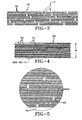
- FIG. 2 which shows a partial plan view of the overlay ply 18 according to the invention, illustrate more clearly that the overlay ply comprises sections 21 consisting of discontinuous lengths of cords which are embedded in a sheet of a suitable rubber compound.
- the cord sections 21 in the overlay ply are aligned end to end in a plurality of spaced apart mutually parallel rows.
- the interruptions 22 between the adjacent ends of any two sections of cord in one row are offset longitudinally with respect to interruptions 26 between cord sections in the immediate adjacent row. In other words, the interruptions in a given row are staggered with respect to the interruptions in an adjacent row.
- interruption refers to and is used interchangeably with the term "cut”.
- the spacing of the interruptions in this manner is necessary to ensure an optimum distribution of reinforcing cord portions around the circumference of the tire, required for high speed, wear and noise performances of the tire.
- the disposition of the interruptions of the individual cords in adjacent rows do not follow any regular pattern such as, for example, a constant spacing between the interruptions in the circumferential direction. It is believed that a particularly advantageous construction is obtained when the spacings between the interruptions in adjacent rows are distributed in a nonuniform predetermined sequence manner.
- cut pattern generators which are known in the computer art, can be used to derive sequences for calculating the positions of the interruptions in the circumferential direction.
- each of the cord sections contributes with substantially equal strength to help the overlay ply 18 to fulfill its function as a circumferential restrictor ply. It is therefore preferred although not required to use plies with cord sections of substantially equal length in each of the rows as illustrated in FIG. 2 .
- substantially equal length is meant that the length of the cord sections in each row does not vary by more than about 5% of the average section length.
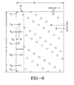
- the discrete segments 19 are wrapped around the circumference of the tire 10 and have a width w between lateral edges and are joined to adjacent segments at the lateral edges to form the overlay.
- Each segment 19 has a repeated pattern of cuts having a cut width C arranged in six rows, each cut being spaced at least 100 mm from a cut in an adjacent row and each segment is offset in the lateral direction a distance Dc from an adjacent segment by at least 3 mm, the cut width C being greater than the distance Dc.
- the overlay cord lengths within a respective row is a length L in the range of 200 to 500 mm
- the cut pitch within the respective rows is of any percentage P of the tire circumference in the range 18 to 30%.
- the circumferential offset between two adjacent segments is any percentage 0 of the tire circumference in the range of 0.5 to 2%.
- the restrictive effect of the overlay ply 18 across the width of the tire 10 such that, for example, the shoulder portions of the tire are more rigid than the center portion of the tire.
- This can be achieved by providing cord sections 21 in the shoulder portion of the tire 10 which have a length which is larger than the length of the cord sections 21 in the central portion of the tire 10.
- the cord sections 21 in each row may decrease in length from the shoulder portions of the tire to the central portion of the tire.
- the material for the textile reinforcing elements may be selected from one or more of the conventional materials that are used in tires such as nylon, rayon, aramid, polyester, etc. It is desirable, however, that the reinforcing elements have a relatively high modulus of elongation, i.e. a load capacity greater than 20 Newtons at 4% elongation.
- the present invention permits the use of high modulus cords since the expansion of the overlay ply during the curing process can be taken up entirely by the gaps between the cord sections. The interruptions or gaps open slightly under the action of the expansion forces and accommodate the change in circumferential length of the overlay ply.
- the overlay plies 18 can be made from conventional ply stock containing uncut lengths of cord which may be calendered in the usual manner.
- the cords are subsequently cut into sections at regularly spaced intervals. This separation of the reinforcing cords into sections 21 may be effected by cutting, punching, grinding, slicing, abrading or a similar process.
- the cutting operation can take place at the calender itself, prior to winding up the ply material, or just prior to the application of the overlay ply 18 to the tire at the tire building machine.
- the tires 10 of the present invention can be manufactured in a very cost-effective manner.
- a different overlay ply had to be used for each tire size for effectively accommodating the stresses in the ply cords
- the present invention allows for a standard overlay ply to be used in a variety of tire sizes.
- the interruptions 22 that are provided in the cords of the overlay ply 18 of the present invention contribute towards an effective control of the tensions in the overlay ply 18.
- FIG. 3 illustrates an overlay ply 30 wherein the interruptions 32 of a group of 3 adjacent cord sections lie in the same radial plane.
- the width of the cut in other words the width that is occupied by the interruptions of adjacent cords which lie in the same radial plane is indicated in FIG. 3 by the distance C. While the embodiment of FIG. 3 illustrates a plurality of interruptions 32 which lie in the same radial plane, they can equally be disposed in a plane which makes an angle with the radial direction.
- the interruptions are preferably staggered in the circumferential direction and distributed around the circumference of the tire in an irregular manner.
- width C of the cuts in the same radial plane corresponds to about 10% of the width of the overlay ply.
- This width corresponds to about the width that 20 reinforcing cords occupy in the overlay ply 18, 30, 60 of a large size passenger tire.
- the interruptions between the successively aligned cord sections are of negligible width, i.e. the total width of the interruptions per circumferentially extending row of cords is less than about 4% of the circumferential development of the tire.
- FIG. 4 illustrates a partial plan view of the overlay ply 60 of a tire of size 185/65 R 14:
- the width W of the ply 60 is about 140 mm and it contains about 25 rows of reinforcing cord sections 61, per 25 mm (1 inch) of width, i.e. the overlay ply 60 is composed of a total of about 138 rows of aligned reinforcing cord sections 61.
- the interruptions 62 between cord sections are arranged in groups such that the interruptions in about six adjacent rows lie in the same radial plane.
- the portion of the overlay ply that is illustrated represents about one half of the total ply. In the portion shown each row comprises about two and a half cord sections 61.
- the cord sections each have a length of about 200 TO 500 mm which is about 1/5 of the circumference of the tire.
- the individual cord sections are not shown on FIG. 4 , but are illustrated as groups of adjacent cord sections.
- FIG. 5 illustrates an enlarged view of the portion of the ply of FIG. 4 that is encircled.
- the individual cord sections 61 and the interruptions 62 between cord sections 61 can be clearly seen.
- the cord sections are shown as lines.
- the interior noise measurement performed in 185/65R14 size tires has a 3dB(A) average reduction of the 26 th interior noise order, which is the most tonal order in the speed average order spectrum and which is induced by the tire overlay, over the 80-20 km per hour speed range.
- the subjective noise test results that were performed on the same tire constructions show that the new pitched overlay tire construction improves the subjective pattern-whine noise performance in the 80-20 km per hour speed range by a 0.75 subjective point in average versus the prior overlay construction known in the art.
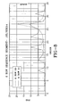
- FIG, 7 shows the predicted noise effect of the 1.16% circumferential offset of adjacent segments 19, expressed in percentage of the tire circumference.
- the six rows proposed arrangement within each segment 19 is predicted to have noise characteristics as shown in the chart in FIG. 8 .
- overlay ply comprising a single layer of textile reinforcing cords
- tires comprising overlay plies with more than one layer of textile reinforcing cords, such as overlay plies comprising two separate axially spaced apart ply portions.
- Such ply portions can either be disposed radially outwardly of the edges of the radially outermost belt ply or they can be radially interposed between the belt plies at the edges thereof.
- the invention also applies to tires comprising multiple, superposed layers of textile reinforcing cords. It is indeed well known in the tire art that the high speed durability of tires can be further increased by superposing more than one reinforcing layer in the crown area of the tire.
Landscapes
- Engineering & Computer Science (AREA)
- Mechanical Engineering (AREA)
- Tires In General (AREA)
Claims (5)
- Reifen (10) mit einer äußeren Lauffläche und einer inneren Karkasse mit einer Gürtelstruktur (16, 17), die Gürtelstruktur umfasst eine Abdecklage (18, 30, 60), die durch parallele Korde, die in Umfangsrichtung ausgerichtet sind, verstärkt ist, mit einer Breite (W) zwischen seitlich äußersten Kanten (20), wobei die Abdecklage (18, 30, 60) ein Muster von Einschnitten innerhalb einzelner Segmente (19) hat; wobei jedes Segment (19) um den Umfang des Reifens (10) herumgeschlagen ist und eine Breite (W) zwischen den Seitenkanten (20) des jeweiligen Segments (19) hat und an den Seitenkanten an benachbarte Segmenten angrenzt; wobei jedes Segment (19) durch ein wiederholtes Muster von Einschnitten (22) mit einer Schnittbreite (C), die in Reihen angeordnet sind, gekennzeichnet ist, wobei jeder Einschnitt (22) in Umfangsrichtung mindestens 100 mm von dem Einschnitt in der benachbarten Reihe beabstandet ist, und wobei jedes Segment (19) um einen Abstand (Dc) von mindestens 3 mm von dem benachbarten Segment seitlich versetzt ist, wobei dieser Abstand kleiner als die Einschnittbreite (C) ist, wobei die Abdecklagen-Kordlängen innerhalb der jeweiligen Reihen von gleich welcher Länge (L) im Bereich von 200 bis 500 mm sind, wobei die Einschnittteilung in den jeweiligen Reihen gleich welchen Prozentsatz (P) des Reifenumfangs (M) im Bereich von 8 bis 30 % beträgt, wobei der Versatz in Umfangsrichtung zwischen zwei benachbarten Segmenten gleich welchen Prozentsatz (O) des Reifenumfangs im Bereich von 0,5 bis 2 % beträgt.
- Reifen nach Anspruch 1, wobei das wiederholte Muster von Einschnitten (22) in jedem der Segmente (19) ein wiederholtes Muster von Einschnitten ist, die in sechs Reihen angeordnet sind.
- Reifen nach Anspruch 2, wobei das wiederholte Muster von Einschnitten (22) in den sechs Reihen an Positionen von 0, 53, 21, 89, 34 beziehungsweise 72 Prozent der Einschnittteilung (P) des Kords relativ zu der Reihe R1 angeordnet ist und in jeder Reihe mit der Einschnittlänge (L) wiederholt wird.
- Reifen nach mindestens einem der vorangehenden Ansprüche, wobei der Einschnittteilungs-Prozentsatz (P) 20,9 % beträgt.
- Reifen nach mindestens einem der vorangehenden Ansprüche, wobei der Versatz (O) in Umfangsrichtung zwischen zwei benachbarten Segmenten, ausgedrückt im Prozentsatz des Reifenumfangs M, 1,16 % beträgt.
Applications Claiming Priority (2)
| Application Number | Priority Date | Filing Date | Title |
|---|---|---|---|
| US692107 | 2003-10-23 | ||
| US10/692,107 US6935393B2 (en) | 2003-10-23 | 2003-10-23 | Tire having an overlay for noise improvement |
Publications (2)
| Publication Number | Publication Date |
|---|---|
| EP1526003A1 EP1526003A1 (de) | 2005-04-27 |
| EP1526003B1 true EP1526003B1 (de) | 2008-05-21 |
Family
ID=34394564
Family Applications (1)
| Application Number | Title | Priority Date | Filing Date |
|---|---|---|---|
| EP04105084A Expired - Lifetime EP1526003B1 (de) | 2003-10-23 | 2004-10-15 | Reifen mit Abdeckung zur Geräuschverbesserung |
Country Status (5)
| Country | Link |
|---|---|
| US (1) | US6935393B2 (de) |
| EP (1) | EP1526003B1 (de) |
| JP (1) | JP2005126061A (de) |
| BR (1) | BRPI0404356A (de) |
| DE (1) | DE602004013899D1 (de) |
Families Citing this family (7)
| Publication number | Priority date | Publication date | Assignee | Title |
|---|---|---|---|---|
| US20070144649A1 (en) * | 2005-12-27 | 2007-06-28 | Patrick Joseph King | Overlay configuration for a tire |
| JP2008087608A (ja) * | 2006-10-02 | 2008-04-17 | Bridgestone Corp | 空気入りラジアルタイヤ |
| US20100300595A1 (en) * | 2009-06-01 | 2010-12-02 | Serge Julien Auguste Imhoff | Pneumatic tire with an overlay reinforcement |
| FR2953761B1 (fr) * | 2009-12-10 | 2012-04-13 | Michelin Soc Tech | Pneumatique pour vehicules lourds comportant une couche d'elements de renforcement circonferentiels constituee d'une partie centrale et de deux parties axialement exterieures |
| JP6014542B2 (ja) | 2013-04-25 | 2016-10-25 | 株式会社ブリヂストン | 航空機用タイヤ |
| JP6133138B2 (ja) * | 2013-06-04 | 2017-05-24 | 株式会社ブリヂストン | 航空機用空気入りタイヤ |
| FR3061674A1 (fr) * | 2017-01-12 | 2018-07-13 | Compagnie Generale Des Etablissements Michelin | Assemblage comprenant un tissu partiellement rompable et une structure porteuse |
Family Cites Families (28)
| Publication number | Priority date | Publication date | Assignee | Title |
|---|---|---|---|---|
| US3095026A (en) | 1959-08-07 | 1963-06-25 | Firestone Tire & Rubber Co | Pneumatic tire |
| US3095027A (en) | 1959-10-12 | 1963-06-25 | Firestone Tire & Rubber Co | Pneumatic tire |
| DE1091890B (de) * | 1960-01-25 | 1960-10-27 | Phoenix Gummiwerke Ag | Kraftfahrzeugluftreifen |
| US3570574A (en) | 1968-07-26 | 1971-03-16 | Gen Tire & Rubber Co | Expansible belt for use in belted pneumatic tires |
| IT999224B (it) | 1973-11-06 | 1976-02-20 | Pirelli | Perfezionamento alla struttura di intermedio per pneumatici radiali e metodo per ottenere tale struttura |
| US4167130A (en) | 1977-12-22 | 1979-09-11 | Owens-Corning Fiberglas Corporation | Method for cutting sheet moulding compound reinforcing strands |
| DE2916445A1 (de) | 1979-04-24 | 1980-11-06 | Continental Gummi Werke Ag | Luftreifen, insbesondere guertelreifen |
| JPS62231802A (ja) * | 1985-12-25 | 1987-10-12 | Bridgestone Corp | 不整地用空気入タイヤ |
| JPS62152834A (ja) * | 1985-12-27 | 1987-07-07 | Bridgestone Corp | 空気入りタイヤ |
| JPS62273837A (ja) * | 1986-05-23 | 1987-11-27 | Yokohama Rubber Co Ltd:The | 乗用車用空気入りラジアルタイヤ |
| JPS63106104A (ja) * | 1986-10-24 | 1988-05-11 | Yokohama Rubber Co Ltd:The | 空気入りタイヤ |
| GB8708977D0 (en) | 1987-04-14 | 1987-05-20 | Goodyear Tire & Rubber | Reinforcing plies for tyres |
| JPH05238207A (ja) * | 1992-02-26 | 1993-09-17 | Bridgestone Corp | 空気入りタイヤ |
| FR2718390A1 (fr) | 1994-04-11 | 1995-10-13 | Michelin & Cie | Pneumatique avec flancs renforcés. |
| FR2728510A1 (fr) * | 1994-12-23 | 1996-06-28 | Michelin & Cie | Pneumatique de rapport de forme h/s inferieur ou egal a 0,6 |
| FR2731654A1 (fr) | 1995-03-16 | 1996-09-20 | Michelin & Cie | Renforcement a zero degre pour pneumatiques et dispositif de coupe pour preparer un tel renforcement |
| FR2734764A1 (fr) | 1995-05-30 | 1996-12-06 | Michelin & Cie | Pneumatique avec une nappe de renforcement a elements circonferentiels. |
| FR2744955B1 (fr) * | 1996-02-20 | 1998-03-20 | Michelin & Cie | Armature de sommet de pneumatique |
| FR2744954B1 (fr) * | 1996-02-20 | 1998-03-20 | Michelin & Cie | Armature de sommet pour pneumatique "poids-lourds" |
| FR2759945B1 (fr) * | 1997-02-24 | 1999-04-02 | Michelin & Cie | Pneumatique de rapport de forme h/s inferieur ou egal a 0,6 |
| FR2770458B1 (fr) * | 1997-11-05 | 1999-12-03 | Michelin & Cie | Armature de sommet pour pneumatique "poids-lours" |
| US6546983B1 (en) | 1998-02-16 | 2003-04-15 | The Goodyear Tire & Rubber Company | Tire with buried overlay |
| KR100631312B1 (ko) * | 1999-05-14 | 2006-10-09 | 소시에떼 드 테크놀로지 미쉐린 | 래디얼 타이어를 위한 크라운 보강물 |
| JP2001039114A (ja) * | 1999-07-28 | 2001-02-13 | Bridgestone Corp | 空気入りラジアルタイヤ |
| WO2001045966A1 (en) | 1999-12-21 | 2001-06-28 | The Goodyear Tire & Rubber Company | Reinforcement package for tires |
| US6668889B1 (en) * | 1999-12-21 | 2003-12-30 | The Goodyear Tire & Rubber Company | Reinforcement package for tires |
| US6394160B1 (en) | 2000-11-29 | 2002-05-28 | The Goodyear Tire & Rubber Company | Tire with segmented belt |
| US6622764B2 (en) * | 2002-02-01 | 2003-09-23 | The Goodyear Tire & Rubber Company | Underlay structure for increased crown stiffening |
-
2003
- 2003-10-23 US US10/692,107 patent/US6935393B2/en not_active Expired - Lifetime
-
2004
- 2004-10-11 BR BR0404356-1A patent/BRPI0404356A/pt not_active IP Right Cessation
- 2004-10-12 JP JP2004297040A patent/JP2005126061A/ja not_active Ceased
- 2004-10-15 DE DE602004013899T patent/DE602004013899D1/de not_active Expired - Fee Related
- 2004-10-15 EP EP04105084A patent/EP1526003B1/de not_active Expired - Lifetime
Also Published As
| Publication number | Publication date |
|---|---|
| BRPI0404356A (pt) | 2005-06-21 |
| EP1526003A1 (de) | 2005-04-27 |
| DE602004013899D1 (de) | 2008-07-03 |
| US20050087280A1 (en) | 2005-04-28 |
| JP2005126061A (ja) | 2005-05-19 |
| US6935393B2 (en) | 2005-08-30 |
Similar Documents
| Publication | Publication Date | Title |
|---|---|---|
| EP0287496B1 (de) | Verstärkungslagen für Luftreifen | |
| CA1295537C (en) | Pneumatic tire | |
| CA2008085C (en) | Belt overlay structure for pneumatic tires | |
| EP0414470B1 (de) | Radialer Luftreifen für hohe Leistung | |
| US5115853A (en) | Pneumatic tire with belt overlay structure reinforced with low denier nylon cords | |
| US7431063B2 (en) | Method for producing a belt structure for a vehicle tyre and vehicle tyre including the belt structure | |
| US7104299B2 (en) | Two piece tire with improved tire tread belt | |
| US4815514A (en) | Belted tire | |
| EP1526003B1 (de) | Reifen mit Abdeckung zur Geräuschverbesserung | |
| CA1071079A (en) | Belted pneumatic tires with zero degree breaker reinforcement, and method of building such tires | |
| US5178703A (en) | Breaker with wound band | |
| US6966351B2 (en) | Tire bead configuration | |
| EP1647395B1 (de) | Verfahren zum Herstellen von Reifen mit einem segmentierten Gürtel | |
| US5332018A (en) | Folded belt reinforcing assembly including spirally wound strip for a pneumatic tire | |
| US20030201046A1 (en) | Two piece tire with improved tire tread belt | |
| EP0401444A2 (de) | Radialer Luftreifen | |
| US20050076989A1 (en) | Tyres for vehicle wheels with improved bead structure | |
| EP3736141B1 (de) | Radialreifen | |
| CA1209022A (en) | Heavy duty low-section pneumatic radial tire and a process for manufacturing the same | |
| EP2202094B1 (de) | Versetzte Zickzackgürtelstruktur für Luftreifen | |
| EP1479535A2 (de) | Zweiteiliger Reifen mit einem verbesserten Verstärkungsgürtel | |
| US20020062906A1 (en) | Method of building a tire and a longitudinal cutter for plies | |
| US20220185019A1 (en) | Tire with protective belt structure | |
| JPH06316202A (ja) | ラジアルタイヤ |
Legal Events
| Date | Code | Title | Description |
|---|---|---|---|
| PUAI | Public reference made under article 153(3) epc to a published international application that has entered the european phase |
Free format text: ORIGINAL CODE: 0009012 |
|
| AK | Designated contracting states |
Kind code of ref document: A1 Designated state(s): AT BE BG CH CY CZ DE DK EE ES FI FR GB GR HU IE IT LI LU MC NL PL PT RO SE SI SK TR |
|
| AX | Request for extension of the european patent |
Extension state: AL HR LT LV MK |
|
| 17P | Request for examination filed |
Effective date: 20051027 |
|
| AKX | Designation fees paid |
Designated state(s): DE FR GB IT |
|
| GRAP | Despatch of communication of intention to grant a patent |
Free format text: ORIGINAL CODE: EPIDOSNIGR1 |
|
| GRAS | Grant fee paid |
Free format text: ORIGINAL CODE: EPIDOSNIGR3 |
|
| GRAA | (expected) grant |
Free format text: ORIGINAL CODE: 0009210 |
|
| AK | Designated contracting states |
Kind code of ref document: B1 Designated state(s): DE FR GB IT |
|
| REG | Reference to a national code |
Ref country code: GB Ref legal event code: FG4D |
|
| REF | Corresponds to: |
Ref document number: 602004013899 Country of ref document: DE Date of ref document: 20080703 Kind code of ref document: P |
|
| PGFP | Annual fee paid to national office [announced via postgrant information from national office to epo] |
Ref country code: DE Payment date: 20081031 Year of fee payment: 5 |
|
| PLBE | No opposition filed within time limit |
Free format text: ORIGINAL CODE: 0009261 |
|
| STAA | Information on the status of an ep patent application or granted ep patent |
Free format text: STATUS: NO OPPOSITION FILED WITHIN TIME LIMIT |
|
| 26N | No opposition filed |
Effective date: 20090224 |
|
| GBPC | Gb: european patent ceased through non-payment of renewal fee |
Effective date: 20081015 |
|
| PG25 | Lapsed in a contracting state [announced via postgrant information from national office to epo] |
Ref country code: IT Free format text: LAPSE BECAUSE OF FAILURE TO SUBMIT A TRANSLATION OF THE DESCRIPTION OR TO PAY THE FEE WITHIN THE PRESCRIBED TIME-LIMIT Effective date: 20080521 |
|
| PG25 | Lapsed in a contracting state [announced via postgrant information from national office to epo] |
Ref country code: GB Free format text: LAPSE BECAUSE OF NON-PAYMENT OF DUE FEES Effective date: 20081015 |
|
| PGFP | Annual fee paid to national office [announced via postgrant information from national office to epo] |
Ref country code: FR Payment date: 20091027 Year of fee payment: 6 |
|
| PG25 | Lapsed in a contracting state [announced via postgrant information from national office to epo] |
Ref country code: DE Free format text: LAPSE BECAUSE OF NON-PAYMENT OF DUE FEES Effective date: 20100501 |
|
| REG | Reference to a national code |
Ref country code: FR Ref legal event code: ST Effective date: 20110531 |
|
| PG25 | Lapsed in a contracting state [announced via postgrant information from national office to epo] |
Ref country code: FR Free format text: LAPSE BECAUSE OF NON-PAYMENT OF DUE FEES Effective date: 20091102 |