EP1525843B1 - Sphygmomanometer und Innenkern dafür - Google Patents
Sphygmomanometer und Innenkern dafür Download PDFInfo
- Publication number
- EP1525843B1 EP1525843B1 EP04025241.3A EP04025241A EP1525843B1 EP 1525843 B1 EP1525843 B1 EP 1525843B1 EP 04025241 A EP04025241 A EP 04025241A EP 1525843 B1 EP1525843 B1 EP 1525843B1
- Authority
- EP
- European Patent Office
- Prior art keywords
- wrist
- cuff
- spring
- protrusion
- cuff spring
- Prior art date
- Legal status (The legal status is an assumption and is not a legal conclusion. Google has not performed a legal analysis and makes no representation as to the accuracy of the status listed.)
- Expired - Lifetime
Links
Images


Classifications
-
- A—HUMAN NECESSITIES
- A61—MEDICAL OR VETERINARY SCIENCE; HYGIENE
- A61B—DIAGNOSIS; SURGERY; IDENTIFICATION
- A61B5/00—Measuring for diagnostic purposes; Identification of persons
- A61B5/02—Detecting, measuring or recording for evaluating the cardiovascular system, e.g. pulse, heart rate, blood pressure or blood flow
- A61B5/021—Measuring pressure in heart or blood vessels
- A61B5/022—Measuring pressure in heart or blood vessels by applying pressure to close blood vessels, e.g. against the skin; Ophthalmodynamometers
- A61B5/02233—Occluders specially adapted therefor
Definitions
- the present invention relates to a wrist sphygmomanometer, which is mounted on a wrist and is capable of measuring blood pressure, and a cuff spring used as a core material of the cuff band of the wrist sphygmomanometer.
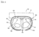
- the sphygmomanometer 50 is an integral type manometer in which a cuff band 52 wound around a wrist 100 is unified to a sphygmomanometer main body 51.
- An air bag 54 is disposed inside the cuff band 52, and air is supplied to the air bag 54 from the sphygmomanometer main body 51 to expand the air bag, which presses against arteries (ulnar artery 101, and radial artery 102) passing along the wrist 100 to measure blood pressure.
- numerals 104, 105, and 106 in FIG. 5 indicate a tendon, the ulna, and a radius, respectively.
- the cuff spring (clip plate) 53 included in the cuff band 52 as a core material of the cuff band 52 is formed in a curved surface to fit the semicircle on the side of the pulsation part of the wrist 100 where the ulnar artery 101, the radial artery 102, and the tendon 104 are positioned.
- the expanded portion of the air bag 54 is not properly formed near the ulnar artery 101 and the radial artery 102, and cannot suitably press these ulnar artery 101 and radial artery 102. In such a case, there is a possibility that the blood pressure cannot be measured with high accuracy.
- Other conventional sphygmomanometers includes the one in which the air bag of the cuff band is divided into two portions at the center in a peripheral direction of the cuff spring, and air is supplied to the respective air bags so that the expanded portions of the respective air bags press the ulnar artery 101 and the radial artery 102 individually.
- the air bag since the air bag is separated, a problem is that the cuff band is difficult to be wound around the wrist 100.
- the cuff spring 53 inside the cuff band 52 is substantially an elliptical cylinder having an arc shaped cross section of which a portion is cut out in a peripheral direction.
- the curvature of the cuff spring 53 is constant in an axial direction of the cuff spring 53.
- the wrist 100 around which the cuff band 52 is wound gradually enlarges from the hand towards the arm, when the cuff band 52 bundling the cuff spring 53 is wound around the wrist 100, the cuff spring 53 does not fit the wrist 100, and the cuff band 52 is apt to shift in the longitudinal and peripheral directions of the wrist 100. Accordingly, measurement of blood pressure with the sphygmomanometer 50 is not stable in this case, and the accuracy of blood pressure measurement is lowered.
- an object of the present invention is to provide a wrist sphygmomanometer capable of accurately measuring blood pressure, and a cuff spring used as a core material of a cuff band for the wrist sphygmomanometer.
- a first aspect of the present invention provides a wrist sphygmomanometer in accordance with claim 1.
- a second aspect of the present invention provides the wrist sphygmomanometer wherein the cuff spring has a slit formed at an arbitrary position in the axial direction so as to extend in the peripheral direction, and both sides of the slit in the axial direction of the cuff spring are formed having different curvatures with each other.
- a third aspect of the present invention provides the wrist sphygmomanometer according to either of aspects 1 or 2 of the present invention, the cuff spring is provided with an reinforcing rib formed integrally with the protrusion to reinforce the protrusion.
- a fourth aspect of the present invention provides a cuff spring formed by a plate-like elastic member.
- a sphygmomanometer main body having a pressure pump is mounted on a mount portion, and a cuff spring having a curved shape becoming a core material of a cuff band to be wound around a wrist has a protrusion protruding inward formed in a nearly central position in the peripheral direction.
- the protrusion is positioned between positions corresponding to each of the two arteries passing through the pulsation part of the wrist in the peripheral direction of the cuff spring, when the cuff band is wound around the wrist with the cuff spring properly fit the semicircle on the side of the pulsation part of the wrist.
- the air bag avoids the protrusion in the peripheral direction of the cuff spring and adequately expands at both sides of the protrusion. Therefore, each of the two arteries of the wrist can be effectively pressed by the expanded portions, thereby improving measurement accuracy of the blood pressure.
- the cuff spring has a slit extending in the peripheral direction formed at an arbitrary position in the axial direction, and both sides of the slit in the axial direction of the cuff spring are formed having different curvatures with each other, which contributes to fitting the semicircle on the side of the pulsation part of the wrist of which a thickness changes gradually, so that the space between the cuff band and the wrist can be reduced when the cuff band is wound around the wrist.
- the cuff band can be prevented from shifting in the longitudinal direction and in the peripheral direction of the wrist, blood pressure can be stably measured so that the accuracy in blood pressure measurement can be improved.
- the reinforcing rib to reinforce the protrusion is provided integrally with the protrusion on the cuff spring, the rigidity of the protrusion is increased. As a result, deformation of the protrusion can be prevented, and the expanded portions of the air bag formed on both sides of the protrusion in the peripheral direction of the cuff spring can press more effectively the arteries passing along the wrist.
- the cuff spring used for the wrist sphygmomanometer according to aspects 1 can be obtained.
- FIG. 1 is a perspective view showing an embodiment of a wrist sphygmomanometer relating to the present invention.
- FIG. 2 is a sectional view taken along the II-II line in FIG. 1 .
- the wrist sphygmomanometer 10 shown in FIG. 1 includes a sphygmomanometer main body 11 and a cuff band 12 attached to the sphygmomanometer main body, in which the sphygmomanometer main body 11 is mounted on a wrist 1 by winding the cuff band 12 around the wrist 1 to carry out measurement of blood pressure using an oscillometric method.
- the wrist sphygmomanometer 10 comprises the sphygmomanometer main body 11, the cuff band 12, and a cuff spring 13.
- an ulnar artery 5 and a radial artery 6 also pass in parallel.
- These ulnar artery 5 and radial artery 6 are placed on one side of the ulna 2 and the radius 3 in the wrist 1, namely, placed at an interval in the radial pulse region 4 of the wrist 1.
- a plurality of tendons 7 pass positioned between the ulnar artery 5 and the radial artery 6.
- main machineries for measuring blood pressure such as a pressure pump, a control valve for reduction of pressure, a pressure sensor, and a controller to control these equipment (not shown) are housed in an upper case 14 and a lower case 15 which are joined at their opening sides to each other as shown in FIG. 1 .
- a liquid crystal display portion 16 and various switches 17 are disposed on the top face of the upper case 14.
- a battery 18 is installed on a side of the sphygmomanometer main body 11.
- measured blood pressure or pulse count is displayed, for instance, with digital display.
- the cuff band 12 includes the cuff spring 13 having a curved surface as a core material, as will be described in detail later, and has an air bag 19 disposed inside as shown in FIG. 1 and FIG. 2 .
- the cuff band 12 is wound around the wrist 1 and fixed using a face fastener 20 provided inside. Air is supplied from the pressure pump of the sphygmomanometer main body 11 to the air bag 19 of the cuff band 12 in a state that the cuff band 12 is wound and fixed around the wrist 1, so that the wrist 1 is pressed by the air pressure.
- the cuff spring 13 is formed with flexible synthetic resin and the like, and molded in a curved surface to fit the semicircle on the side of the pulsation part 4 of the wrist 1 as shown in FIGs 2 , 3A , 3B , and 4 .
- the cuff spring 13 is substantially an elliptical cylinder having an elliptical arcuate shape cross section having a cut portion 21 from which a part in the peripheral direction is cut away wherein by enlarging the cut portion 21, the diameter is accordingly expanded, and by narrowing the cut portion 21, the diameter is accordingly reduced.
- a mount portion 22 is formed at a nearly central position in the peripheral direction so as to oppose to the removed portion 21.
- the mount portion 22 comprises a plurality of lock claw pieces 23 and a screwing piece 24, and these lock claw pieces 23 and screwing piece 24 are cut up from the cuff spring 13 so as to be formed integrally with the cuff spring 13.
- the lock claw pieces 23 are locked with the lower case 15 of the sphygmomanometer main body 11, and the screwing piece 24 is screwed thereto.
- the sphygmomanometer main body 11 is mounted on the mount portion 22 of the cuff spring 13.
- An opening 25 is formed on the mount portion 22.
- a communicating tube (not shown) communicating between the pressure pump of the sphygmomanometer main body 11 and the air bag 19 of the cuff band 12 is inserted through the opening 25.
- the protrusion 26 is placed at a position opposing to the tendon 7 in the pulsation part 4 of the wrist 1 so that the cuff spring 13 appropriately fits the semicircle on the side of the pulsation part 4 of the wrist 1, and when the cuff band 12 is wound around the wrist 1 in this state, the protrusion 26 is placed, as shown in FIG.
- reinforcing ribs 27 are integrally formed with the protrusion 26 on the outside of the protrusion 26.
- a plurality of reinforcing ribs 27 are provided at predetermined intervals in the axial direction of the cuff spring 13 to reinforce the protrusion 26 so that rigidity of the protrusion 26 can be increased as shown in FIGs. 3A and 3B , and FIG. 4 .
- the slit 28 extending in the peripheral direction from the cut portion 21 to the mount portion 22 is formed, symmetrically in FIG. 4 , at an optional position in the axial direction, in the present embodiment at the center position, in the axial direction.
- a portion excepting the mount portion 22 and the protrusion 26 of the cuff spring 13 is divided into a hand-side divided portion 29 and an arm-side divided portion 30 in the axial direction by these slits 28, and these two divided portions are formed having different curvatures.
- curvature Rb of the arm-side divided portion 30 is formed larger than curvature Ra of the hand-side divided portion 29.
- the cuff spring 13 of the cuff band 12 follows the changes in thickness of the wrist 1, to fit the semicircle on the side of the pulsation part 4 of the wrist 1. Namely, the space between the cuff band 12 and the wrist 1 is decreased.
- the cuff band 12 is wound around the wrist 1 and fixed using the face fastener 20.
- the protrusion 26 on the cuff spring 13 in the cuff band 12 is placed so as to oppose to the tendon 7 on the side of the pulsation part 4 of the wrist 1 so that the cuff spring 13 adequately fit the semicircle on the side of the pulsation part 4 on the wrist 1.
- the switches 17 of the sphygmomanometer main body 11 are turned on while the hand is lightly opened with the palm of a hand facing upward, with an elbow in touch with the top face of a desk or the like to keep the wrist 1 at the height of a heart.
- air is supplied from the pressure pump of the sphygmomanometer main body 11 to the air bag 19 of the cuff band 12 to expand the air bag 19.
- the air bag 19 adequately expands at both sides of the protrusion 26 in the peripheral direction of the cuff spring 13 in the cuff band 12 so that these expanded portions press effectively the ulnar artery 5 and the radial artery 6 which are on both sides of the tendons 7 in the wrist 1.
- blood pressure is measured by a pressure sensor or the like of the sphygmomanometer main body 11, and the measurement result is displayed on the display 16 of the sphygmomanometer main body 11.
- the slit 28 is provided at a central position in the axial direction, and a portion excepting the mount portion 22 and the protrusion 26 of the cuff spring 13 is divided into the hand-side divided portion 29 and the arm-side divided portion 30.
- the slit 28 may be formed at a plurality of positions in the axial direction of the cuff spring 13, respectively to divide a portion excepting the mount portion 22 and the protrusion 26 of the cuff spring 13 into 3 or more, so that the curvatures of respective divided portions are subsequently increased from the hand side toward the arm side.
- the protrusion 26, the reinforcing rib 27 and the slit 28 are provided in the cuff spring 13.
- the slit 28 may not be formed, although having the protrusion 26 and the reinforcing rib 27 provided, or the slit 28 may be formed, although not having the protrusion 26 and the reinforcing rib 27 provided.
- the sphygmomanometer main body 11 an example of attaching the cuff band 12 to the sphygmomanometer main body 11 is shown, but it is needless to say that like a general sphygmomanometer, the sphygmomanometer main body 11 and the cuff band 12 may be cut out from each other and separately formed.
- a wrist sphygmomanometer comprises a cuff spring formed in a curved shape to fit the semicircle on the side of the pulsation part of the wrist, having a mount portion formed outside; a cuff band including the cuff spring as a core material, having an air bag inside, and wound around a wrist; and a sphygmomanometer main body mounted on the mount portion of the cuff spring, having a pressure pump for supplying air to the air bag, wherein the cuff spring has a protrusion protruding inward formed in a nearly central position in a peripheral direction.
Landscapes
- Health & Medical Sciences (AREA)
- Life Sciences & Earth Sciences (AREA)
- Cardiology (AREA)
- Vascular Medicine (AREA)
- Engineering & Computer Science (AREA)
- Medical Informatics (AREA)
- Physics & Mathematics (AREA)
- Ophthalmology & Optometry (AREA)
- Biophysics (AREA)
- Pathology (AREA)
- Dentistry (AREA)
- Biomedical Technology (AREA)
- Heart & Thoracic Surgery (AREA)
- Physiology (AREA)
- Molecular Biology (AREA)
- Surgery (AREA)
- Animal Behavior & Ethology (AREA)
- General Health & Medical Sciences (AREA)
- Public Health (AREA)
- Veterinary Medicine (AREA)
- Measuring Pulse, Heart Rate, Blood Pressure Or Blood Flow (AREA)
Claims (4)
- Handgelenks-Sphygmomanometer (10), umfassend:eine Manschettenfeder (13) mit einem äußeren Montagebereich (22), die mit einer gekrümmten Form gebildet ist, um an der Seite des Pulsbereichs (4) des Handgelenks (1) zu passen;ein Manschettenband (12), das die Manschettenfeder (13) als Kern enthält, das eine darin angeordnete Lufttasche (19) hat und dazu ausgelegt ist, um das Handgelenk (1) herum gewickelt zu sein; undeinen Sphygmomanometer-Hauptkörper (11), der an den Montagebereich (22) montiert ist und eine Druckpumpe umfasst, um der Lufttasche (19) Luft zuzuführen,dadurch gekennzeichnet, dass die Manschettenfeder (13) einen nach innen vorstehenden Vorsprung (26) hat, der an einer nahezu zentralen Position zwischen Positionen gebildet ist, die jeder der zwei durch den Pulsbereich (4) des Handgelenks (1) verlaufenden Arterien entsprechen, in einer Umfangsrichtung der Manschettenfeder (13).
- Handgelenks-Sphygmomanometer (10) nach Anspruch 1, dadurch gekennzeichnet, dass die Manschettenfeder (13) einen Schlitz (28) hat, der an einer beliebigen Position in der axialen Richtung derart gebildet ist, dass er sich in einer Umfangsrichtung erstreckt, und dass beide Seiten des Schlitzes (28) in der axialen Richtung der Manschettenfeder (13) mit zueinander unterschiedlichen Krümmungen gebildet sind.
- Handgelenks-Sphygmomanometer (10) nach einem der Ansprüche 1 oder 2, dadurch gekennzeichnet, dass die Manschettenfeder (13) mit einer Verstärkungsrippe (27) versehen ist, die integral mit dem Vorsprung (26) gebildet ist, um den Vorsprung (26) zu verstärken.
- Handgelenks-Sphygmomanometer (10) nach einem der Ansprüche 1 bis 3, dadurch gekennzeichnet, dass die Manschettenfeder (13) durch ein plattenartiges elastisches Element gebildet ist.
Priority Applications (1)
| Application Number | Priority Date | Filing Date | Title |
|---|---|---|---|
| EP07101595.2A EP1779774B1 (de) | 2003-10-24 | 2004-10-22 | Handgelenk-Sphygmomanometer und Manschettenfeder dafür |
Applications Claiming Priority (2)
| Application Number | Priority Date | Filing Date | Title |
|---|---|---|---|
| JP2003364466A JP4166665B2 (ja) | 2003-10-24 | 2003-10-24 | 手首用血圧計及びカフスプリング |
| JP2003364466 | 2003-10-24 |
Related Child Applications (2)
| Application Number | Title | Priority Date | Filing Date |
|---|---|---|---|
| EP07101595.2A Division EP1779774B1 (de) | 2003-10-24 | 2004-10-22 | Handgelenk-Sphygmomanometer und Manschettenfeder dafür |
| EP07101595.2A Division-Into EP1779774B1 (de) | 2003-10-24 | 2004-10-22 | Handgelenk-Sphygmomanometer und Manschettenfeder dafür |
Publications (3)
| Publication Number | Publication Date |
|---|---|
| EP1525843A2 EP1525843A2 (de) | 2005-04-27 |
| EP1525843A3 EP1525843A3 (de) | 2005-05-25 |
| EP1525843B1 true EP1525843B1 (de) | 2014-03-05 |
Family
ID=34386543
Family Applications (2)
| Application Number | Title | Priority Date | Filing Date |
|---|---|---|---|
| EP07101595.2A Expired - Lifetime EP1779774B1 (de) | 2003-10-24 | 2004-10-22 | Handgelenk-Sphygmomanometer und Manschettenfeder dafür |
| EP04025241.3A Expired - Lifetime EP1525843B1 (de) | 2003-10-24 | 2004-10-22 | Sphygmomanometer und Innenkern dafür |
Family Applications Before (1)
| Application Number | Title | Priority Date | Filing Date |
|---|---|---|---|
| EP07101595.2A Expired - Lifetime EP1779774B1 (de) | 2003-10-24 | 2004-10-22 | Handgelenk-Sphygmomanometer und Manschettenfeder dafür |
Country Status (3)
| Country | Link |
|---|---|
| US (2) | US7374543B2 (de) |
| EP (2) | EP1779774B1 (de) |
| JP (1) | JP4166665B2 (de) |
Families Citing this family (27)
| Publication number | Priority date | Publication date | Assignee | Title |
|---|---|---|---|---|
| JP4306381B2 (ja) * | 2003-09-17 | 2009-07-29 | オムロンヘルスケア株式会社 | 脈波測定装置用手首固定具および脈波測定装置 |
| JP4166665B2 (ja) * | 2003-10-24 | 2008-10-15 | 日本精密測器株式会社 | 手首用血圧計及びカフスプリング |
| US20060111637A1 (en) * | 2004-11-23 | 2006-05-25 | Jacober Jeffrey M | Wrist-mount blood pressure monitor with auditory feature |
| US20060111636A1 (en) * | 2004-11-23 | 2006-05-25 | Jacober Jeffrey M | Wrist-mount blood pressure monitor |
| US20070073173A1 (en) * | 2005-09-27 | 2007-03-29 | Caihealth, Inc. | Blood pressure sphygmomanometer for use with a common apparatus |
| US20070100243A1 (en) * | 2005-10-31 | 2007-05-03 | Calhealth, Inc. | Blood pressure sphygmomanometer for use with a common apparatus |
| SE529044C2 (sv) * | 2006-02-01 | 2007-04-17 | Per Danielsson | Blodtrycksmätare |
| KR20080068471A (ko) * | 2007-01-19 | 2008-07-23 | 삼성전자주식회사 | 휴대형 생체 신호 측정 장치 |
| JP5169552B2 (ja) * | 2008-07-07 | 2013-03-27 | オムロンヘルスケア株式会社 | 血圧情報測定装置用カフおよびこれを備えた血圧情報測定装置 |
| JP5176881B2 (ja) * | 2008-11-04 | 2013-04-03 | オムロンヘルスケア株式会社 | 血圧計および血圧計用充電ユニット |
| WO2010098022A1 (ja) * | 2009-02-26 | 2010-09-02 | テルモ株式会社 | 状態監視装置 |
| JP5243301B2 (ja) * | 2009-02-26 | 2013-07-24 | テルモ株式会社 | 生体動態測定装置 |
| JP5243300B2 (ja) * | 2009-02-26 | 2013-07-24 | テルモ株式会社 | 生体動態測定装置 |
| JP2011161115A (ja) * | 2010-02-15 | 2011-08-25 | Terumo Corp | 状態監視装置 |
| KR101350935B1 (ko) * | 2012-02-16 | 2014-01-15 | 제주대학교 산학협력단 | 혈압 측정용 신축성 고무링 커프 |
| JP6051964B2 (ja) | 2013-03-07 | 2016-12-27 | オムロンヘルスケア株式会社 | 血圧測定用カフ、および、血圧測定用カフの製造方法 |
| CN103393411B (zh) * | 2013-08-12 | 2015-03-25 | 苏波 | 手腕式监护器 |
| KR20170024985A (ko) | 2015-08-27 | 2017-03-08 | 삼성전자주식회사 | 무동력 가압부를 갖는 혈압계 |
| CN105686817A (zh) * | 2016-03-29 | 2016-06-22 | 深圳金亿帝医疗设备股份有限公司 | 血压计袖带和手表式电子血压计 |
| TWM547950U (zh) | 2016-05-31 | 2017-09-01 | 宜強科技股份有限公司 | 不具加壓泵的穿戴式血壓量測裝置 |
| JP6777535B2 (ja) * | 2016-12-28 | 2020-10-28 | オムロン株式会社 | 血圧計および血圧測定方法並びに機器 |
| JP7237576B2 (ja) * | 2018-12-27 | 2023-03-13 | オムロンヘルスケア株式会社 | 血圧測定装置 |
| US20220296104A1 (en) * | 2019-04-04 | 2022-09-22 | Beijing Taiya Technology Co., Ltd. | Pulse meter and control method therefor |
| CN110432880B (zh) * | 2019-08-13 | 2021-10-26 | 西南医科大学附属中医医院 | 一次性使用血压计袖带套 |
| JP7083933B1 (ja) * | 2021-03-25 | 2022-06-13 | シチズン時計株式会社 | 血圧計用腕帯 |
| CN114767083B (zh) * | 2022-05-09 | 2025-11-04 | 西安力邦医疗电子有限公司 | 一种新型血压测量定位装置及应用 |
| USD1118935S1 (en) * | 2024-09-20 | 2026-03-17 | Shenzhen Jamr Technology Co., Ltd. | Wrist type blood pressure monitor |
Family Cites Families (15)
| Publication number | Priority date | Publication date | Assignee | Title |
|---|---|---|---|---|
| US3633567A (en) * | 1969-08-11 | 1972-01-11 | Survival Technology | Pneumatically actuated pressure dressing |
| JPS59232531A (ja) * | 1983-06-15 | 1984-12-27 | 松下電工株式会社 | 血圧計 |
| JPS61238229A (ja) * | 1985-04-13 | 1986-10-23 | 松下電工株式会社 | 血圧計のカフ帯 |
| JPH02261678A (ja) | 1989-03-31 | 1990-10-24 | Brother Ind Ltd | 往復印字の印字位置ずれ補正機能を有するプリンタ |
| JP2740261B2 (ja) * | 1989-05-15 | 1998-04-15 | 松下電工株式会社 | 手首用血圧計のカフ帯 |
| JP3495789B2 (ja) * | 1994-08-11 | 2004-02-09 | セイコーエプソン株式会社 | 携帯型脈波計測装置 |
| US5840037A (en) * | 1995-04-19 | 1998-11-24 | A & D Company, Limited | Sphygmomanometer |
| JP3853973B2 (ja) * | 1998-04-21 | 2006-12-06 | 日本精密測器株式会社 | 手首用血圧計 |
| WO2000015139A2 (en) * | 1998-09-16 | 2000-03-23 | Circaid Medical Products, Inc. | Compression device with compression measuring system |
| JP3235602B2 (ja) * | 1999-09-28 | 2001-12-04 | オムロン株式会社 | 生体圧迫装置 |
| DE60223747T2 (de) | 2001-05-07 | 2008-10-30 | Omron Healthcare Co., Ltd. | Am Handgelenk zu tragende Manschette eines Blutdruckmessgeräts |
| JP3818220B2 (ja) * | 2002-06-03 | 2006-09-06 | オムロンヘルスケア株式会社 | 手首式血圧計用カフ |
| US20040193084A1 (en) * | 2003-03-27 | 2004-09-30 | Arvik Enterprises, Llc | Vein compressor device |
| JP4166665B2 (ja) * | 2003-10-24 | 2008-10-15 | 日本精密測器株式会社 | 手首用血圧計及びカフスプリング |
| SE529044C2 (sv) * | 2006-02-01 | 2007-04-17 | Per Danielsson | Blodtrycksmätare |
-
2003
- 2003-10-24 JP JP2003364466A patent/JP4166665B2/ja not_active Expired - Lifetime
-
2004
- 2004-10-22 EP EP07101595.2A patent/EP1779774B1/de not_active Expired - Lifetime
- 2004-10-22 US US10/970,723 patent/US7374543B2/en not_active Expired - Lifetime
- 2004-10-22 EP EP04025241.3A patent/EP1525843B1/de not_active Expired - Lifetime
-
2007
- 2007-12-19 US US12/000,977 patent/US8292821B2/en not_active Expired - Fee Related
Also Published As
| Publication number | Publication date |
|---|---|
| JP4166665B2 (ja) | 2008-10-15 |
| US20090005694A1 (en) | 2009-01-01 |
| EP1525843A2 (de) | 2005-04-27 |
| EP1779774A2 (de) | 2007-05-02 |
| EP1525843A3 (de) | 2005-05-25 |
| US8292821B2 (en) | 2012-10-23 |
| EP1779774A3 (de) | 2007-05-30 |
| US20050283084A1 (en) | 2005-12-22 |
| US7374543B2 (en) | 2008-05-20 |
| JP2005124883A (ja) | 2005-05-19 |
| EP1779774B1 (de) | 2014-03-19 |
Similar Documents
| Publication | Publication Date | Title |
|---|---|---|
| US8292821B2 (en) | Wrist sphygmomanometer and cuff spring for the same | |
| EP1048267B1 (de) | Handgelenk-blutdruckmesser | |
| JP3952957B2 (ja) | 手首式血圧計用カフ | |
| US8690788B2 (en) | Living body information measuring apparatus | |
| JPH09238910A (ja) | 手首血圧計のカフ | |
| JP4363220B2 (ja) | 血圧計 | |
| KR100772281B1 (ko) | 혈압계용 커프스 및 혈압계 | |
| JP2006158543A (ja) | 手首用血圧計及びカフスプリング | |
| JP4184429B2 (ja) | 手首用血圧計及びカフスプリング | |
| JP2669858B2 (ja) | 手首用血圧計 | |
| JP7107822B2 (ja) | 血圧計用カフ | |
| JP4186873B2 (ja) | 血圧計 | |
| JP7556200B2 (ja) | カフ構造体、及び、血圧測定装置 | |
| JP2010137110A (ja) | 生体情報測定装置 | |
| CN111787855B (zh) | 生物体信息测定装置 | |
| CN215191511U (zh) | 一种腕带式血压测量装置 | |
| JPH11299748A (ja) | 手首用血圧計 | |
| EP3545826B1 (de) | Unterstützungswerkzeug | |
| JP2017127366A (ja) | 腕帯装着補助具及び装着補助具付きの腕帯 | |
| JP2010075731A (ja) | 生体情報測定装置 | |
| JP2010088505A (ja) | 生体圧迫装置、その製造方法及び血圧測定装置 | |
| JP3465428B2 (ja) | 血圧計 | |
| JP2001087231A (ja) | 血圧計 | |
| JP2005319171A (ja) | 生体情報測定装置 | |
| CN119730779A (zh) | 血压测定装置 |
Legal Events
| Date | Code | Title | Description |
|---|---|---|---|
| PUAI | Public reference made under article 153(3) epc to a published international application that has entered the european phase |
Free format text: ORIGINAL CODE: 0009012 |
|
| PUAL | Search report despatched |
Free format text: ORIGINAL CODE: 0009013 |
|
| AK | Designated contracting states |
Kind code of ref document: A2 Designated state(s): AT BE BG CH CY CZ DE DK EE ES FI FR GB GR HU IE IT LI LU MC NL PL PT RO SE SI SK TR |
|
| AX | Request for extension of the european patent |
Extension state: AL HR LT LV MK |
|
| AK | Designated contracting states |
Kind code of ref document: A3 Designated state(s): AT BE BG CH CY CZ DE DK EE ES FI FR GB GR HU IE IT LI LU MC NL PL PT RO SE SI SK TR |
|
| AX | Request for extension of the european patent |
Extension state: AL HR LT LV MK |
|
| 17P | Request for examination filed |
Effective date: 20051118 |
|
| AKX | Designation fees paid |
Designated state(s): AT BE BG CH CY CZ DE DK EE ES FI FR GB GR HU IE IT LI LU MC NL PL PT RO SE SI SK TR |
|
| 17Q | First examination report despatched |
Effective date: 20060920 |
|
| 17Q | First examination report despatched |
Effective date: 20060920 |
|
| GRAP | Despatch of communication of intention to grant a patent |
Free format text: ORIGINAL CODE: EPIDOSNIGR1 |
|
| INTG | Intention to grant announced |
Effective date: 20130916 |
|
| GRAS | Grant fee paid |
Free format text: ORIGINAL CODE: EPIDOSNIGR3 |
|
| GRAA | (expected) grant |
Free format text: ORIGINAL CODE: 0009210 |
|
| AK | Designated contracting states |
Kind code of ref document: B1 Designated state(s): AT BE BG CH CY CZ DE DK EE ES FI FR GB GR HU IE IT LI LU MC NL PL PT RO SE SI SK TR |
|
| REG | Reference to a national code |
Ref country code: GB Ref legal event code: FG4D |
|
| REG | Reference to a national code |
Ref country code: CH Ref legal event code: EP |
|
| REG | Reference to a national code |
Ref country code: AT Ref legal event code: REF Ref document number: 654301 Country of ref document: AT Kind code of ref document: T Effective date: 20140315 |
|
| REG | Reference to a national code |
Ref country code: IE Ref legal event code: FG4D |
|
| REG | Reference to a national code |
Ref country code: DE Ref legal event code: R096 Ref document number: 602004044498 Country of ref document: DE Effective date: 20140417 |
|
| REG | Reference to a national code |
Ref country code: AT Ref legal event code: MK05 Ref document number: 654301 Country of ref document: AT Kind code of ref document: T Effective date: 20140305 |
|
| REG | Reference to a national code |
Ref country code: NL Ref legal event code: VDEP Effective date: 20140305 |
|
| PG25 | Lapsed in a contracting state [announced via postgrant information from national office to epo] |
Ref country code: AT Free format text: LAPSE BECAUSE OF FAILURE TO SUBMIT A TRANSLATION OF THE DESCRIPTION OR TO PAY THE FEE WITHIN THE PRESCRIBED TIME-LIMIT Effective date: 20140305 Ref country code: SE Free format text: LAPSE BECAUSE OF FAILURE TO SUBMIT A TRANSLATION OF THE DESCRIPTION OR TO PAY THE FEE WITHIN THE PRESCRIBED TIME-LIMIT Effective date: 20140305 Ref country code: CY Free format text: LAPSE BECAUSE OF FAILURE TO SUBMIT A TRANSLATION OF THE DESCRIPTION OR TO PAY THE FEE WITHIN THE PRESCRIBED TIME-LIMIT Effective date: 20140305 Ref country code: FI Free format text: LAPSE BECAUSE OF FAILURE TO SUBMIT A TRANSLATION OF THE DESCRIPTION OR TO PAY THE FEE WITHIN THE PRESCRIBED TIME-LIMIT Effective date: 20140305 |
|
| PG25 | Lapsed in a contracting state [announced via postgrant information from national office to epo] |
Ref country code: CZ Free format text: LAPSE BECAUSE OF FAILURE TO SUBMIT A TRANSLATION OF THE DESCRIPTION OR TO PAY THE FEE WITHIN THE PRESCRIBED TIME-LIMIT Effective date: 20140305 Ref country code: BG Free format text: LAPSE BECAUSE OF FAILURE TO SUBMIT A TRANSLATION OF THE DESCRIPTION OR TO PAY THE FEE WITHIN THE PRESCRIBED TIME-LIMIT Effective date: 20140605 Ref country code: NL Free format text: LAPSE BECAUSE OF FAILURE TO SUBMIT A TRANSLATION OF THE DESCRIPTION OR TO PAY THE FEE WITHIN THE PRESCRIBED TIME-LIMIT Effective date: 20140305 Ref country code: EE Free format text: LAPSE BECAUSE OF FAILURE TO SUBMIT A TRANSLATION OF THE DESCRIPTION OR TO PAY THE FEE WITHIN THE PRESCRIBED TIME-LIMIT Effective date: 20140305 Ref country code: BE Free format text: LAPSE BECAUSE OF FAILURE TO SUBMIT A TRANSLATION OF THE DESCRIPTION OR TO PAY THE FEE WITHIN THE PRESCRIBED TIME-LIMIT Effective date: 20140305 Ref country code: RO Free format text: LAPSE BECAUSE OF FAILURE TO SUBMIT A TRANSLATION OF THE DESCRIPTION OR TO PAY THE FEE WITHIN THE PRESCRIBED TIME-LIMIT Effective date: 20140305 |
|
| PG25 | Lapsed in a contracting state [announced via postgrant information from national office to epo] |
Ref country code: PL Free format text: LAPSE BECAUSE OF FAILURE TO SUBMIT A TRANSLATION OF THE DESCRIPTION OR TO PAY THE FEE WITHIN THE PRESCRIBED TIME-LIMIT Effective date: 20140305 Ref country code: SK Free format text: LAPSE BECAUSE OF FAILURE TO SUBMIT A TRANSLATION OF THE DESCRIPTION OR TO PAY THE FEE WITHIN THE PRESCRIBED TIME-LIMIT Effective date: 20140305 Ref country code: ES Free format text: LAPSE BECAUSE OF FAILURE TO SUBMIT A TRANSLATION OF THE DESCRIPTION OR TO PAY THE FEE WITHIN THE PRESCRIBED TIME-LIMIT Effective date: 20140305 |
|
| REG | Reference to a national code |
Ref country code: DE Ref legal event code: R097 Ref document number: 602004044498 Country of ref document: DE |
|
| PG25 | Lapsed in a contracting state [announced via postgrant information from national office to epo] |
Ref country code: PT Free format text: LAPSE BECAUSE OF FAILURE TO SUBMIT A TRANSLATION OF THE DESCRIPTION OR TO PAY THE FEE WITHIN THE PRESCRIBED TIME-LIMIT Effective date: 20140707 |
|
| PLBE | No opposition filed within time limit |
Free format text: ORIGINAL CODE: 0009261 |
|
| STAA | Information on the status of an ep patent application or granted ep patent |
Free format text: STATUS: NO OPPOSITION FILED WITHIN TIME LIMIT |
|
| PG25 | Lapsed in a contracting state [announced via postgrant information from national office to epo] |
Ref country code: DK Free format text: LAPSE BECAUSE OF FAILURE TO SUBMIT A TRANSLATION OF THE DESCRIPTION OR TO PAY THE FEE WITHIN THE PRESCRIBED TIME-LIMIT Effective date: 20140305 |
|
| 26N | No opposition filed |
Effective date: 20141208 |
|
| REG | Reference to a national code |
Ref country code: DE Ref legal event code: R097 Ref document number: 602004044498 Country of ref document: DE Effective date: 20141208 |
|
| PG25 | Lapsed in a contracting state [announced via postgrant information from national office to epo] |
Ref country code: SI Free format text: LAPSE BECAUSE OF FAILURE TO SUBMIT A TRANSLATION OF THE DESCRIPTION OR TO PAY THE FEE WITHIN THE PRESCRIBED TIME-LIMIT Effective date: 20140305 Ref country code: MC Free format text: LAPSE BECAUSE OF FAILURE TO SUBMIT A TRANSLATION OF THE DESCRIPTION OR TO PAY THE FEE WITHIN THE PRESCRIBED TIME-LIMIT Effective date: 20140305 Ref country code: LU Free format text: LAPSE BECAUSE OF FAILURE TO SUBMIT A TRANSLATION OF THE DESCRIPTION OR TO PAY THE FEE WITHIN THE PRESCRIBED TIME-LIMIT Effective date: 20141022 |
|
| REG | Reference to a national code |
Ref country code: CH Ref legal event code: PL |
|
| GBPC | Gb: european patent ceased through non-payment of renewal fee |
Effective date: 20141022 |
|
| REG | Reference to a national code |
Ref country code: IE Ref legal event code: MM4A |
|
| PG25 | Lapsed in a contracting state [announced via postgrant information from national office to epo] |
Ref country code: LI Free format text: LAPSE BECAUSE OF NON-PAYMENT OF DUE FEES Effective date: 20141031 Ref country code: CH Free format text: LAPSE BECAUSE OF NON-PAYMENT OF DUE FEES Effective date: 20141031 Ref country code: GB Free format text: LAPSE BECAUSE OF NON-PAYMENT OF DUE FEES Effective date: 20141022 |
|
| REG | Reference to a national code |
Ref country code: FR Ref legal event code: PLFP Year of fee payment: 12 |
|
| PG25 | Lapsed in a contracting state [announced via postgrant information from national office to epo] |
Ref country code: IE Free format text: LAPSE BECAUSE OF NON-PAYMENT OF DUE FEES Effective date: 20141022 |
|
| PG25 | Lapsed in a contracting state [announced via postgrant information from national office to epo] |
Ref country code: GR Free format text: LAPSE BECAUSE OF FAILURE TO SUBMIT A TRANSLATION OF THE DESCRIPTION OR TO PAY THE FEE WITHIN THE PRESCRIBED TIME-LIMIT Effective date: 20140606 |
|
| PG25 | Lapsed in a contracting state [announced via postgrant information from national office to epo] |
Ref country code: HU Free format text: LAPSE BECAUSE OF FAILURE TO SUBMIT A TRANSLATION OF THE DESCRIPTION OR TO PAY THE FEE WITHIN THE PRESCRIBED TIME-LIMIT; INVALID AB INITIO Effective date: 20041022 Ref country code: TR Free format text: LAPSE BECAUSE OF FAILURE TO SUBMIT A TRANSLATION OF THE DESCRIPTION OR TO PAY THE FEE WITHIN THE PRESCRIBED TIME-LIMIT Effective date: 20140305 |
|
| REG | Reference to a national code |
Ref country code: FR Ref legal event code: PLFP Year of fee payment: 13 |
|
| REG | Reference to a national code |
Ref country code: FR Ref legal event code: PLFP Year of fee payment: 14 |
|
| REG | Reference to a national code |
Ref country code: FR Ref legal event code: PLFP Year of fee payment: 15 |
|
| PGFP | Annual fee paid to national office [announced via postgrant information from national office to epo] |
Ref country code: IT Payment date: 20231031 Year of fee payment: 20 Ref country code: FR Payment date: 20231023 Year of fee payment: 20 Ref country code: DE Payment date: 20231031 Year of fee payment: 20 |
|
| REG | Reference to a national code |
Ref country code: DE Ref legal event code: R071 Ref document number: 602004044498 Country of ref document: DE |