EP1525784B1 - Landwirtschaftliche Verteilmaschine - Google Patents
Landwirtschaftliche Verteilmaschine Download PDFInfo
- Publication number
- EP1525784B1 EP1525784B1 EP04024118A EP04024118A EP1525784B1 EP 1525784 B1 EP1525784 B1 EP 1525784B1 EP 04024118 A EP04024118 A EP 04024118A EP 04024118 A EP04024118 A EP 04024118A EP 1525784 B1 EP1525784 B1 EP 1525784B1
- Authority
- EP
- European Patent Office
- Prior art keywords
- adjusting means
- central part
- angle adjusting
- disposed
- distributor
- Prior art date
- Legal status (The legal status is an assumption and is not a legal conclusion. Google has not performed a legal analysis and makes no representation as to the accuracy of the status listed.)
- Expired - Lifetime
Links
- 0 CC/*=C/C(C)*CC(*)(C1(C)C)C=*(C2CC=CC2)*(C)C1(*=C)S(B(C1C(*)CC2)C1=*)CCC2C1*C1 Chemical compound CC/*=C/C(C)*CC(*)(C1(C)C)C=*(C2CC=CC2)*(C)C1(*=C)S(B(C1C(*)CC2)C1=*)CCC2C1*C1 0.000 description 4
Images


Classifications
-
- A—HUMAN NECESSITIES
- A01—AGRICULTURE; FORESTRY; ANIMAL HUSBANDRY; HUNTING; TRAPPING; FISHING
- A01B—SOIL WORKING IN AGRICULTURE OR FORESTRY; PARTS, DETAILS, OR ACCESSORIES OF AGRICULTURAL MACHINES OR IMPLEMENTS, IN GENERAL
- A01B73/00—Means or arrangements to facilitate transportation of agricultural machines or implements, e.g. folding frames to reduce overall width
- A01B73/02—Folding frames
- A01B73/06—Folding frames foldable about a vertical axis
- A01B73/065—Folding frames foldable about a vertical axis to a position essentially forward of the axis, in relation to the direction of travel
-
- A—HUMAN NECESSITIES
- A01—AGRICULTURE; FORESTRY; ANIMAL HUSBANDRY; HUNTING; TRAPPING; FISHING
- A01M—CATCHING, TRAPPING OR SCARING OF ANIMALS; APPARATUS FOR THE DESTRUCTION OF NOXIOUS ANIMALS OR NOXIOUS PLANTS
- A01M7/00—Special adaptations or arrangements of liquid-spraying apparatus for purposes covered by this subclass
- A01M7/005—Special arrangements or adaptations of the spraying or distributing parts, e.g. adaptations or mounting of the spray booms, mounting of the nozzles, protection shields
- A01M7/0053—Mounting of the spraybooms
- A01M7/0057—Mounting of the spraybooms with active regulation of the boom position
-
- A—HUMAN NECESSITIES
- A01—AGRICULTURE; FORESTRY; ANIMAL HUSBANDRY; HUNTING; TRAPPING; FISHING
- A01M—CATCHING, TRAPPING OR SCARING OF ANIMALS; APPARATUS FOR THE DESTRUCTION OF NOXIOUS ANIMALS OR NOXIOUS PLANTS
- A01M7/00—Special adaptations or arrangements of liquid-spraying apparatus for purposes covered by this subclass
- A01M7/005—Special arrangements or adaptations of the spraying or distributing parts, e.g. adaptations or mounting of the spray booms, mounting of the nozzles, protection shields
- A01M7/0071—Construction of the spray booms
- A01M7/0075—Construction of the spray booms including folding means
Definitions
- the invention relates to an agricultural distribution machine according to the preamble of claim 1.
- Such an agricultural distribution machine has been described in practice become known.
- this agricultural distributor of the side arm is arranged by means of a relatively wide hinge on its underside on the central frame part to prevent tilting or twisting of the boom about its longitudinal axis.
- a hydraulic cylinder is arranged between the side arm and the middle frame part in order to be able to angle the side arm.
- the upper bearing point between the center frame and side arm contributes nothing.
- the US-A-4,288,034 and US-A-3,887,132 show a field sprayer with a frame, a reservoir and a manifold linkage.
- the distributor linkage has a central part, which is arranged on the frame and are arranged on the pivotable about upright axles side arm. Between the arranged at the central part hinge elements of the side arm and the upper flange of the side arm designed as a hydraulic cylinder Anwinkelkar is arranged. Furthermore, a strut is arranged between the upper flange and a rear part of the arm projecting to lift the side arms when folded into the forward projecting transport position in a forward-upwardly projecting position.
- the invention has for its object to provide a simple embodiment of the Anwinkelmechanismus for the side arms of a distributor linkage of a distributor.
- the respective upper hinge element by means of which the respective side arm is arranged on the central part, is arranged directly on the Anwinkelsch and another strut directly to the middle part, and that the Anwinkelstoff and the strut spaced from each other hinged to the middle part frame are.
- the articulation means and the strut are advantageously seen in plan view, opening from the hinge on the side arm to each other.
- the strut is designed as an adjustable screw.
- the respective lower joint by means of which the respective side arms are articulated on the middle part, an upright hinge axis and a pointing at least in the direction of travel hinge axis, based on the working position of the distributor linkage having.
- a simple design of the lower joint is achieved.
- a particularly advantageous embodiment of the joint results from the fact that this is designed as a ball joint.
- the side arm In order to be able to angling with distribution linkages, the side arm about an upright axis from a transversely extending to the direction elongated working position about an upright pivot axis in a forward projecting folded transport position without pivoting the side arm when angling out of its transversely stretched to the direction of travel , It is provided that the actuating element and angling means associated with a side arm are adjusted in a predetermined and common manner by means of suitable adjusting means when the angling means are actuated in such a way that the respective side arm maintains its position transversely to the direction of travel when the angle of attack is changed.
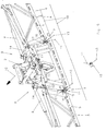
- the distributor linkage 1 is provided for arrangement on an agricultural distribution machine, not shown, which has a frame, reservoir.
- the Distributor linkage 1 has a central frame part 2 and laterally adjoining side arms 3 and 4.
- the middle frame part 2 is arranged on the frame of a distributor via a height adjustment linkage.
- the side arm 3,4 consist of sub-segments 5, which are interconnected by means of joints 6, so that the side arm 3,4 are collapsible in a transport position.
- the side arms 3,4 are arranged on the middle frame part 2 via a lower hinge 7 and upper hinge elements 8 and via a respectively arranged between the central frame part 2 and the inner sub-segment 5 of the respective side arm 3,4 hydraulic cylinder 9 to the through the lower hinge 7 and the upper joint part 10 of the upper joint elements 8 extending hinge axis 11 and foldable. Furthermore, between the upper joint part 10 and the middle frame part 2, a preferably formed as a hydraulic cylinder 11 Anwinkelstoff, which is part of the upper joint elements 8, assigned to angling of the respective side arm 3.4 of the distributor linkage about an axis 13 pointing in the direction of travel.
- an adjustable strut 14 which is part of the upper joint elements 8, arranged between the upper inner part of the side arm 3,4 in the region of the upper hinge part and the middle frame part 2.
- the Anwinkelstoff designed as a hydraulic cylinder 11 and designed as an adjustable screw strut 14 are spaced apart hinged to the center frame part 2.
- the Anwinkelstoff 11 and the strut 14 are seen in plan view of the hinge 10 on the boom 3, 4 opening to each other, such as Fig. 4 shows.
- This ball joint 15 has an upright hinge pin 16.
- the side arm 3,4 is due to the ball joint 15 about an axis pointing in the direction of travel 12 axis 18 or in other words, about a transverse to the longitudinal axis 17 of the bolt 16 axis 13 due to the upper articulation by the hinge elements 8 of the side arm. 3 4 pivotable relative to the middle frame part 2.
- the respective side arm 3, 4 Due to the formation of the lower joint 7 as a ball joint 15, by means of which the respective side arm 3, 4 is articulated to the central frame part 2, the respective side arm 3, 4 from the in Fig. 1 shown extended position in the in Fig. 2 illustrated angled position to angle the angle A relative to the horizontal 18.
- the Fig. 3 is the left side arm 3 in the extended position accordingly Fig. 1 shown, while the right boom 4 accordingly Fig. 1 in the Fig. 2 is angled.
- Angling takes place in that by means of the hydraulic cylinder 11, the upper joint part 10 is pulled in the direction of the center frame part 2, that is, the hydraulic cylinder 11 is retracted.
- the hydraulic cylinder 9 is extended.
- the hydraulic cylinders 9 and 11 are not over shown lines connected to a circuit, not shown, so that when operating the acting as a "Einwinkelzylinders" hydraulic cylinder 11 at the same time acting as a folding cylinder hydraulic cylinder 9 is extended.
- the respectively angled side arm retains its position transversely to the direction of travel when the angle of angling is changed and does not tilt about an axis running transversely to the direction of travel of the linkage.
- the ball joint 15 Due to the design of the lower joint 7 as a ball joint 15, it is not necessary to provide a complex intermediate frame between the central frame part 2 and the side arm 3, 4, to allow the angle.
- the ball joint 15 thus simultaneously assumes the function of a joint when cornering, as well as the function of a joint when folding in and out of the side arms 3, 4 of the distributor linkage 1.
- the ball joint 15 has at least one upright hinge axis 11 and extending at least in the direction of travel hinge axis thirteenth , based on the working position of the distributor linkage 1, on.
Landscapes
- Life Sciences & Earth Sciences (AREA)
- Engineering & Computer Science (AREA)
- Environmental Sciences (AREA)
- Insects & Arthropods (AREA)
- Pest Control & Pesticides (AREA)
- Wood Science & Technology (AREA)
- Zoology (AREA)
- Soil Sciences (AREA)
- Mechanical Engineering (AREA)
- Catching Or Destruction (AREA)
- Threshing Machine Elements (AREA)
- Agricultural Machines (AREA)
- Pretreatment Of Seeds And Plants (AREA)
- Soil Working Implements (AREA)
- Fertilizing (AREA)
- Transplanting Machines (AREA)
- Separation By Low-Temperature Treatments (AREA)
Description
- Die Erfindung betrifft eine landwirtschaftliche Verteilmaschine gemäß des Oberbegriffes des Patentanspruches 1.
- Eine derartige landwirtschaftliche Verteilmaschine ist in der Praxis bekannt geworden beschrieben. Bei dieser landwirtschaftlichen Verteilmaschine ist der Seitenausleger mittels eines relativ breiten Gelenkes auf seiner Unterseite am Mittelrahmenteil angeordnet, um ein Verkanten oder Verdrehen des Auslegers um seine Längsachse zu verhindern. Im oberen Bereich ist zwischen dem Seitenausleger und dem Mittelrahmenteil ein Hydraulikzylinder angeordnet, um den Seitenausleger anwinkeln zu können. Hinsichtlich der Stabilität bezüglich des Verdrehens des Seitenauslegers um seine Längsachse trägt der obere Lagerpunkt zwischen Mittelteilrahmen und Seitenausleger nichts bei.
- Die
US-A- 4 288 034 undUS-A- 3 887 132 zeigen eine Feldspritze mit einem Rahmen, einem Vorratsbehälter und einem Verteilergestänge. Das Verteilergestänge weist ein Mittelteil auf, welches am Rahmen angeordnet ist und an den um aufrechte Achsen einschwenkbare Seitenausleger angeordnet sind. Zwischen den an dem Mittelteil angeordneten Gelenkelementen des Seitenauslegers und dem Obergurt des Seitenauslegers ist ein als Hydraulikzylinder ausgebildetes Anwinkelmittel angeordnet. Des weiteren ist zwischen dem Obergurt und einem am Mittelteil angeordneten, nach hinten ragenden Arm eine Strebe angeordnet, um die Seitenausleger beim Einklappen in die nach vorn ragende Transportstellung in eine nach vorn-oben ragende Position anzuheben. - Der Erfindung liegt die Aufgabe zugrunde, eine einfache Ausgestaltung des Anwinkelmechanismus für die Seitenausleger eines Verteilergestänges einer Verteilmaschine zu schaffen.
- Diese Aufgabe wird erfindungsgemäß dadurch gelöst, dass das jeweilige obere Gelenkelement, mittels welchem der jeweilige Seitenausleger am Mittelteil angeordnet ist, jeweils über das Anwinkelmittel und einer weiteren Strebe unmittelbar an dem Mittelteil angeordnet ist, und dass das Anwinkelmittel und die Strebe beabstandet zueinander am Mittelteilrahmen angelenkt sind. Infolge dieser Maßnahmen ergibt sich eine definierte Anordnung des oberen Gelenkpunktes zwischen dem Mittelteilrahmen und dem Seitenausleger. Hierbei sind in vorteilhafter Weise das Anlenkmittel und die Strebe in Draufsicht gesehen, sich von dem Gelenk am Seitenausleger öffnend zueinander angeordnet.
- Um Fertigungstoleranzen auszugleichen, damit der Seitenausleger in seiner aufrechten Ausrichtung entsprechend angeordnet ist, ist vorgesehen, dass die Strebe als einstellbare Schraubspindel ausgebildet ist.
- Um zu ermöglichen, dass der Seitenausleger gegenüber dem Mittelteil durch Verschwenken um eine in Fahrtrichtung verlaufende Achse angewinkelt und um eine aufrechte Achse in eine Transportstellung eingeklappt werden kann, ist vorgesehen, dass das jeweilige untere Gelenk, mittels welchem die jeweiligen Seitenausleger am Mittelteil angelenkt sind, eine aufrechte Gelenkachse und eine zumindest in Fahrtrichtung weisende Gelenkachse, bezogen auf die Arbeitsstellung des Verteilergestänges, aufweist. Hierdurch wird eine einfache Ausbildung des unteren Gelenkes erreicht. Eine besonders vorteilhafte Ausbildung des Gelenkes ergibt sich dadurch, dass dieses als Kugelgelenk ausgebildet ist.
- Um bei Verteilergestängen, deren Seitenausleger um eine aufrechte Achse aus einer sich quer zur Fahrtrichtung erstreckenden lang gestreckten Arbeitsstellung um eine aufrechte Schwenkachse in eine nach vorn ragende zusammengefaltete Transportstellung gebracht werden, ohne Verschwenkbewegung des Seitenauslegers beim Anwinkeln aus seiner quer zur Fahrtrichtung gestreckten Lage anwinkeln zu können, ist vorgesehen, dass das einem Seitenausleger zugeordnete Stellelement und Anwinkelmittel mittels geeigneter Einstellmittel beim Betätigen des Anwinkelmittels in vorgegebener und gemeinsamer Weise verstellt werden und zwar derart, dass der jeweilige Seitenausleger bei Veränderung des Anwinkelwinkels seine Lage quer zur Fahrtrichtung beibehält.
- Weitere Einzelheiten der Erfindung sind der Beispielsbeschreibung und den Zeichnungen zu entnehmen.
- Hierbei zeigen
- Fig. 1
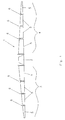
- das Verteilergestänge einer landwirtschaftlichen Feldspritze in der Ansicht von hinten in gestreckter Lage und in Prinzipdarstellung,
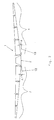
- Fig. 2
- das Verteilergestänge der Feldspritze nach
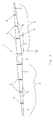
Fig. 1 , wobei die Seitenausleger angewinkelt sind, - Fig. 3
- das Verteilergestänge der Feldspritze nach
Fig. 1 , wobei der rechte Seitenausleger angewinkelt ist, - Fig. 4
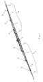
- das Verteilergestänge einer landwirtschaftlichen Feldspritze in der Ansicht von hinten und in perspektivischer Darstellung und in gestreckter Lage,
- Fig. 5
- das Verteilergestänge gemäß
Fig. 4 , wobei der mittlere Bereich in Perspektivdarstellung von hinten gesehen dargestellt ist, - Fig. 6
- das Mittelteil und das daran anschließende Teil und das diese beiden miteinander verbindende Gelenk in Perspektivdarstellung von hinten und
- Fig. 7
- das untere mittlere rechte Gelenk in Perspektivdarstellung.
- Das Verteilergestänge 1 ist zur Anordnung an einer nicht dargestellten landwirtschaftlichen Verteilmaschine, die einen Rahmen, Vorratsbehälter aufweist, vorgesehen. Das Verteilergestänge 1 weist ein Mittelrahmenteil 2 und sich hieran seitlich anschließende Seitenausleger 3 und 4 auf. Das Mittelrahmenteil 2 ist über ein Höhenverstellgestänge an dem Rahmen einer Verteilmaschine angeordnet. Die Seitenausleger 3,4 bestehen aus Teilsegmenten 5, die mittels Gelenke 6 miteinander verbunden sind, so dass die Seitenausleger 3,4 in eine Transportstellung zusammenfaltbar sind. Die Seitenausleger 3,4 sind über ein unteres Gelenk 7 und obere Gelenkelemente 8 an dem Mittelrahmenteil 2 angeordnet und über jeweils einen zwischen dem Mittelrahmenteil 2 und dem inneren Teilsegment 5 des jeweiligen Seitenauslegers 3,4 angeordneten Hydraulikzylinder 9 um die durch das untere Gelenk 7 und das obere Gelenkteil 10 der oberen Gelenkelemente 8 verlaufene Gelenkachse 11 ein- und ausfaltbar. Des weiteren ist zwischen dem oberen Gelenkteil 10 und dem Mittelrahmenteil 2 ein vorzugsweise als Hydraulikzylinder 11 ausgebildetes Anwinkelmittel, das Bestandteil der oberen Gelenkelemente 8 ist, zum Anwinkeln des jeweiligen Seitenauslegers 3,4 des Verteilergestänges um eine in Fahrtrichtung weisende Achse 13 zugeordnet. Des weiteren ist zwischen dem oberen inneren Teil des Seitenauslegers 3,4 im Bereich des oberen Gelenkteiles und dem Mittelrahmenteil 2 eine einstellbare Strebe 14, die Bestandteil der oberen Gelenkelemente 8 ist, angeordnet. Das als Hydraulikzylinder 11 ausgebildete Anwinkelmittel und die als einstellbare Schraubspindel ausgebildete Strebe 14 sind beabstandet zueinander am Mittelrahmenteil 2 angelenkt. Somit ist das obere Gelenkmittel 8, mittels welchem der jeweilige Seitenausleger 3,4 am Mittelrahmenteil 2 angeordnet ist, jeweils über das Anwinkelmittel 11 und der weiteren Strebe 14 mit dem Mittelrahmenteil 2 verbunden. Das Anwinkelmittel 11 und die Strebe 14 sind in Draufsicht gesehen von dem Gelenk 10 am Ausleger 3, 4 öffnend zueinander angeordnet, wie
Fig. 4 zeigt. - Das untere Gelenk 7, mittels welchem das innere Teilsegment 5 des jeweiligen Seitenauslegers 3,4 am Mittelrahmenteil 2 angeordnet ist, ist als Kugelgelenk 15 ausgebildet. Dieses Kugelgelenk 15 weist einen aufrecht verlaufenen Gelenkbolzen 16 auf. Um die Mittelachse 17 dieses Gelenkbolzens 16 ist der Seitenausleger 3,4 in Verbindung mit dem Kugelgelenk 15 ein- und ausschwenkbar. Des weiteren ist der Seitenausleger 3,4 aufgrund des Kugelgelenkes 15 um eine in Fahrtrichtung 12 weisende Achse 18 bzw. mit anderen Worten ausgedrückt, um eine quer zur Längsachse 17 des Bolzens 16 verlaufene Achse 13 aufgrund der oberen Anlenkung durch die Gelenkelemente 8 des Seitenauslegers 3, 4 gegenüber dem Mittelrahmenteil 2 verschwenkbar.
- Aufgrund der Ausbildung des unteren Gelenkes 7 als Kugelgelenk 15, mittels welchem der jeweilige Seitenausleger 3, 4 an dem Mittelrahmenteil 2 angelenkt ist, sind die jeweiligen Seitenausleger 3, 4 aus der in
Fig. 1 dargestellten gestreckten Lage in die inFig. 2 dargestellte angewinkelte Lage um den Winkel A gegenüber der Horizontalen 18 anzuwinkeln. In derFig. 3 ist der linke Seitenausleger 3 in gestreckter Lage entsprechendFig. 1 dargestellt, während der rechte Ausleger 4 entsprechendFig. 1 in derFig. 2 angewinkelt ist. - Das Anwinkeln geschieht dadurch, dass mittels des Hydraulikzylinders 11 der obere Gelenkteil 10 in Richtung des Mittelrahmenteils 2 gezogen wird, d.h. der Hydraulikzylinder 11 wird eingefahren. Um gleichzeitig zu verhindern, dass durch diese Anwinkelbewegung des Seitenauslegers 3, 4 der jeweilige Seitenausleger 3, 4 nicht eine Tendenz zum Einfalten aufweist, wird der Hydraulikzylinder 9 ausgefahren. Hierzu sind die Hydraulikzylinder 9 und 11 über nicht dargestellte Leitungen mit einer nicht dargestellten Schaltung verbunden, so dass beim Betätigen des als "Einwinkelzylinders" wirkende Hydraulikzylinder 11 gleichzeitig der als Einfaltzylinder wirkende Hydraulikzylinder 9 ausgefahren wird. Hierdurch behält der jeweils angewinkelte Seitenausleger bei Veränderung des Anwinkelwinkels seine Lage quer zur Fahrtrichtung bei und kippt nicht um eine quer zur Fahrtrichtung des Gestänges verlaufenden Achse.
- Aufgrund der Ausbildung des unteren Gelenkes 7 als Kugelgelenk 15 ist es nicht erforderlich, einen aufwendigen Zwischenrahmen zwischen dem Mittelrahmenteil 2 und dem Seitenausleger 3, 4 vorzusehen, um das Einwinkeln zu ermöglichen. Das Kugelgelenk 15 übernimmt somit gleichzeitig die Funktion eines Gelenkes beim Einwinkeln, wie auch die Funktion eines Gelenkes beim Ein- und Ausfalten der Seitenausleger 3, 4 des Verteilergestänges 1. Das Kugelgelenk 15 weist zumindest eine aufrechte Gelenkachse 11 und eine zumindest in Fahrtrichtung verlaufende Gelenkachse 13, bezogen auf die Arbeitsstellung des Verteilergestänges 1, auf.
Claims (6)
- Landwirtschaftliche Verteilmaschine mit einem Rahmen, Vorratsbehälter und Verteilergestänge, welches in eine sich quer zur Fahrtrichtung erstreckende gestreckte Arbeitsstellung und in eine zusammengefaltete Transportstellung bringbar ist und aus einem am Rahmen höhenverstellbar angeordneten Mittelteilrahmen und sich hieran beiderseits mittels Gelenken angeordneten und zusammenfaltbaren Seitenauslegern besteht, wobei zwischen dem Mittelteilrahmen und jedem Seitenausleger jeweils ein vorzugsweise als Hydraulikzylinder ausgebildetes Stellelement zum Ein- und Ausfalten des Seitenauslegers angeordnet ist und jedem Seitenausleger ein vorzugsweise als Hydraulikzylinder ausgebildetes Anwinkelmittel zum Anwinkeln des Seitenauslegers um eine in Fahrtrichtung verweisende Achse zugeordnet ist, dadurch gekennzeichnet, dass das jeweilige obere Gelenkelement (8), mittels welchem der jeweilige Seitenausleger (3,4) am Mittelteil (2) angeordnet ist, jeweils über das Anwinkelmittel (11) und einer weiteren Strebe (14) unmittelbar an dem Mittelteilrahmen (2) angeordnet sind, und dass das Anwinkelmittel (11) und die Strebe (14) beabstandet zueinander am Mittelteilrahmen (2) angelenkt sind.
- Verteilmaschine nach Anspruch 1, dadurch gekennzeichnet, dass das Anwinkelmittel (11) und die Strebe (14)in Draufsicht gesehen sich von dem Gelenk (10) am Seitenausleger (3,4) öffnend zueinander angeordnet sind.
- Verteilmaschine nach Anspruch 1, dadurch gekennzeichnet, dass die Strebe als einstellbare Schraubspindel (14) ausgebildet ist.
- Verteilmaschine nach Anspruch 1, dadurch gekennzeichnet, dass das jeweilige untere Gelenk (7), mittels welchem die jeweiligen Seitenausleger (3,4) am Mittelteil (2) angelenkt sind, eine aufrechte Gelenkachse (17) und eine zumindest in Fahrtrichtung weisende Gelenkachse (13), bezogen auf die Arbeitsstellung des Verteilergestänges (1) aufweist.
- Verteilmaschine nach Anspruch 4, dadurch gekennzeichnet, dass das untere Gelenk als Kugelgelenk (15) ausgebildet ist.
- Verteilmaschine nach einem oder mehreren der vorstehenden Ansprüche, dadurch gekennzeichnet, dass das einem Seitenausleger zugeordnete Stellelement und Anwinkelmittel mittels geeigneter Einstellmittel beim Betätigen des Anwinkelmittels in vorgegebener und gemeinsamer Weise verstellt werden und zwar derart, dass der jeweilige Seitenausleger bei Veränderung des Anwinkelwinkels seine Lage quer zur Fahrtrichtung beibehält.
Priority Applications (3)
| Application Number | Priority Date | Filing Date | Title |
|---|---|---|---|
| EP06002697A EP1661444B1 (de) | 2003-10-23 | 2004-10-09 | Landwirtschaftliche Verteilmaschine |
| PL04024118T PL1525784T3 (pl) | 2003-10-23 | 2004-10-09 | Rolnicza maszyna rozdzielcza |
| PL06002697T PL1661444T3 (pl) | 2003-10-23 | 2004-10-09 | Rozdzielacz rolniczy |
Applications Claiming Priority (4)
| Application Number | Priority Date | Filing Date | Title |
|---|---|---|---|
| DE2003149325 DE10349325A1 (de) | 2003-10-23 | 2003-10-23 | Landwirtschaftliche Verteilmaschine |
| DE10349326 | 2003-10-23 | ||
| DE10349325 | 2003-10-23 | ||
| DE2003149326 DE10349326A1 (de) | 2003-10-23 | 2003-10-23 | Landwirtschaftliche Verteilmaschine |
Related Child Applications (1)
| Application Number | Title | Priority Date | Filing Date |
|---|---|---|---|
| EP06002697A Division EP1661444B1 (de) | 2003-10-23 | 2004-10-09 | Landwirtschaftliche Verteilmaschine |
Publications (3)
| Publication Number | Publication Date |
|---|---|
| EP1525784A2 EP1525784A2 (de) | 2005-04-27 |
| EP1525784A3 EP1525784A3 (de) | 2005-06-08 |
| EP1525784B1 true EP1525784B1 (de) | 2008-02-20 |
Family
ID=34395066
Family Applications (2)
| Application Number | Title | Priority Date | Filing Date |
|---|---|---|---|
| EP06002697A Expired - Lifetime EP1661444B1 (de) | 2003-10-23 | 2004-10-09 | Landwirtschaftliche Verteilmaschine |
| EP04024118A Expired - Lifetime EP1525784B1 (de) | 2003-10-23 | 2004-10-09 | Landwirtschaftliche Verteilmaschine |
Family Applications Before (1)
| Application Number | Title | Priority Date | Filing Date |
|---|---|---|---|
| EP06002697A Expired - Lifetime EP1661444B1 (de) | 2003-10-23 | 2004-10-09 | Landwirtschaftliche Verteilmaschine |
Country Status (5)
| Country | Link |
|---|---|
| EP (2) | EP1661444B1 (de) |
| AT (2) | ATE387843T1 (de) |
| DE (2) | DE502004006242D1 (de) |
| DK (2) | DK1525784T3 (de) |
| PL (2) | PL1661444T3 (de) |
Cited By (2)
| Publication number | Priority date | Publication date | Assignee | Title |
|---|---|---|---|---|
| DE102016122857A1 (de) | 2016-11-28 | 2018-05-30 | Amazonen-Werke H. Dreyer Gmbh & Co. Kg | Verteilergestänge für eine landwirtschaftliche Verteilmaschine |
| US11800860B2 (en) | 2019-08-21 | 2023-10-31 | Cnh Industrial America Llc | Multi-axis linkage for use with a collapsible boom and agricultural vehicle having same |
Families Citing this family (10)
| Publication number | Priority date | Publication date | Assignee | Title |
|---|---|---|---|---|
| BRPI0703229B1 (pt) | 2007-09-28 | 2019-08-27 | Stapelbroek Trennepohl Atila | barra central para pulverização e/ou distribuição de produtos em formulações pó, líquidos e granulados |
| EP2106694A1 (de) * | 2008-04-02 | 2009-10-07 | Damien Lennon | Sprühvorrichtung |
| CN103766314B (zh) * | 2014-01-16 | 2015-12-23 | 山东希成农业机械科技有限公司 | 一种喷杆喷雾机 |
| GB201409923D0 (en) * | 2014-06-04 | 2014-07-16 | Agco Int Gmbh | Agricultural sprayer boom |
| DE202016100457U1 (de) | 2016-01-29 | 2017-05-04 | Fliegl Agro-Center GmbH | Gülleverteiler |
| DE102016114422A1 (de) * | 2016-08-04 | 2018-02-08 | Amazonen-Werke H. Dreyer Gmbh & Co. Kg | Gestänge eines landwirtschaftlichen Geräts |
| DE102016122854A1 (de) | 2016-11-28 | 2018-05-30 | Amazonen-Werke H. Dreyer Gmbh & Co. Kg | Verteilergestänge für eine landwirtschaftliche Verteilmaschine |
| DE102018213458B4 (de) * | 2018-08-09 | 2023-08-03 | Horsch Leeb Application Systems Gmbh | Landwirtschaftliche Verteilmaschine mit Verteilgestänge |
| FR3085819B1 (fr) * | 2018-09-13 | 2020-09-04 | Pommier S C E B P | Articulation de segments de bras de rampe de pulverisation |
| CN111328791B (zh) * | 2020-04-13 | 2021-10-29 | 李同科 | 一种农业喷药装置 |
Family Cites Families (7)
| Publication number | Priority date | Publication date | Assignee | Title |
|---|---|---|---|---|
| GB622035A (en) * | 1947-03-04 | 1949-04-26 | Pest Control Ltd | Improvements in or relating to spraying machines |
| US3887132A (en) * | 1974-08-12 | 1975-06-03 | Gerald L Widmer | Boom assembly |
| FR2298264A1 (fr) * | 1975-01-24 | 1976-08-20 | Berthoud Sa | Systeme perfectionne de deploiement d'une poutre en deux parties articulees |
| US4288034A (en) * | 1979-03-19 | 1981-09-08 | Gerald Widmer | Boom shock and tilt system |
| FR2669805B1 (fr) * | 1990-11-29 | 1994-05-20 | Agro Electronique France | Dispositif de maintien en position de rangement d'un ensemble de rampe de distribution de produit liquide ou en poudre pour machine agricole. |
| AT397451B (de) * | 1991-04-11 | 1994-04-25 | Haager Volker | Gerät zum versprühen von flüssigkeiten od. dgl. |
| US6119963A (en) * | 1999-07-30 | 2000-09-19 | Case Corporation | Full boom pivot breakaway |
-
2004
- 2004-10-09 DK DK04024118T patent/DK1525784T3/da active
- 2004-10-09 EP EP06002697A patent/EP1661444B1/de not_active Expired - Lifetime
- 2004-10-09 DK DK06002697T patent/DK1661444T3/da active
- 2004-10-09 AT AT06002697T patent/ATE387843T1/de not_active IP Right Cessation
- 2004-10-09 DE DE502004006242T patent/DE502004006242D1/de not_active Expired - Lifetime
- 2004-10-09 PL PL06002697T patent/PL1661444T3/pl unknown
- 2004-10-09 AT AT04024118T patent/ATE386424T1/de not_active IP Right Cessation
- 2004-10-09 PL PL04024118T patent/PL1525784T3/pl unknown
- 2004-10-09 EP EP04024118A patent/EP1525784B1/de not_active Expired - Lifetime
- 2004-10-09 DE DE502004006429T patent/DE502004006429D1/de not_active Expired - Lifetime
Cited By (3)
| Publication number | Priority date | Publication date | Assignee | Title |
|---|---|---|---|---|
| DE102016122857A1 (de) | 2016-11-28 | 2018-05-30 | Amazonen-Werke H. Dreyer Gmbh & Co. Kg | Verteilergestänge für eine landwirtschaftliche Verteilmaschine |
| EP3326462A1 (de) | 2016-11-28 | 2018-05-30 | Amazonen-Werke H. Dreyer GmbH & Co. KG | Verteilergestänge für eine landwirtschaftliche verteilmaschine |
| US11800860B2 (en) | 2019-08-21 | 2023-10-31 | Cnh Industrial America Llc | Multi-axis linkage for use with a collapsible boom and agricultural vehicle having same |
Also Published As
| Publication number | Publication date |
|---|---|
| EP1525784A3 (de) | 2005-06-08 |
| PL1661444T3 (pl) | 2008-05-30 |
| ATE387843T1 (de) | 2008-03-15 |
| ATE386424T1 (de) | 2008-03-15 |
| DK1525784T3 (da) | 2008-03-31 |
| DE502004006429D1 (de) | 2008-04-17 |
| EP1661444A2 (de) | 2006-05-31 |
| PL1525784T3 (pl) | 2008-05-30 |
| EP1661444B1 (de) | 2008-03-05 |
| EP1661444A3 (de) | 2006-06-07 |
| EP1525784A2 (de) | 2005-04-27 |
| DK1661444T3 (da) | 2008-03-31 |
| DE502004006242D1 (de) | 2008-04-03 |
Similar Documents
| Publication | Publication Date | Title |
|---|---|---|
| EP1525784B1 (de) | Landwirtschaftliche Verteilmaschine | |
| DE102006059724A1 (de) | Luftleitvorrichtung für ein Fahrzeug | |
| EP1302342A2 (de) | Federungssystem für eine pendelnd gelagerte Achse | |
| EP1291232B1 (de) | Sitzgestell eines Kraftfahrzeugsitzes mit einem Sitzträger und vorderen Parallelogrammarmen | |
| DE9116475U1 (de) | Schneepflug | |
| DE102016009038B4 (de) | Klappspitzen-Anlenkstück und Verfahren zum Montieren einer Klappspitze | |
| EP3028557B1 (de) | Mäheinrichtung und verfahren zum betreiben einer mäheinrichtung | |
| DE10317812B4 (de) | Landwirtschaftliche Arbeitsmaschine mit einer Fahrwerkslenkung | |
| EP1110443B1 (de) | Mähaufbereiter | |
| DE3148982A1 (de) | Hydraulisch betaetigbare einrichtung an greifern zum daempfen von schwingbewegungen des greiferarmrahmens | |
| CH665237A5 (en) | Bulldozer blade mounting - has double acting rams with linkage on horizontal vehicle axis to blade end hinge | |
| EP2591662B1 (de) | Heuwerbungsmaschine | |
| DE3835367C2 (de) | Vorrichtung für Mähwerke zur Bodenanpassung der Schneidwerke | |
| DE10349325A1 (de) | Landwirtschaftliche Verteilmaschine | |
| AT404534B (de) | Heuwerbungsmaschine | |
| EP1525795A1 (de) | Landwirtschaftliche Verteilmaschine | |
| DE9417893U1 (de) | Mähmaschine | |
| DE10349326A1 (de) | Landwirtschaftliche Verteilmaschine | |
| DE2525345C3 (de) | Planierschildhalterung | |
| DE3433066C1 (de) | Maschine zum pneumatischen Ausbringen von insbesondere körnigem Material | |
| DE69400825T2 (de) | Insbesondere landwirtschaftliches Fahrzeug, umfassend von einem Untergestell getragene Arbeitsorgane und einen Rädersatz, sowie Verbindungsmittel zwischen Untergestell und Rädersatz | |
| DE102006023179A1 (de) | Anbauvorrichtung für eine Landmaschine | |
| DE1582293C3 (de) | Mähmaschine C. van der LeIy N.V, Maasland (Niederlande) | |
| DE20317209U1 (de) | Kreiselschwader | |
| DE10147800A1 (de) | Sitzgestell eines Kraftfahrzeugsitzes mit einem Sitzträger und vorderen Parallelogrammarmen |
Legal Events
| Date | Code | Title | Description |
|---|---|---|---|
| PUAI | Public reference made under article 153(3) epc to a published international application that has entered the european phase |
Free format text: ORIGINAL CODE: 0009012 |
|
| PUAL | Search report despatched |
Free format text: ORIGINAL CODE: 0009013 |
|
| AK | Designated contracting states |
Kind code of ref document: A2 Designated state(s): AT BE BG CH CY CZ DE DK EE ES FI FR GB GR HU IE IT LI LU MC NL PL PT RO SE SI SK TR |
|
| AX | Request for extension of the european patent |
Extension state: AL HR LT LV MK |
|
| AK | Designated contracting states |
Kind code of ref document: A3 Designated state(s): AT BE BG CH CY CZ DE DK EE ES FI FR GB GR HU IE IT LI LU MC NL PL PT RO SE SI SK TR |
|
| AX | Request for extension of the european patent |
Extension state: AL HR LT LV MK |
|
| 17P | Request for examination filed |
Effective date: 20051108 |
|
| AKX | Designation fees paid |
Designated state(s): AT BE BG CH CY CZ DE DK EE ES FI FR GB GR HU IE IT LI LU MC NL PL PT RO SE SI SK TR |
|
| 17Q | First examination report despatched |
Effective date: 20051230 |
|
| GRAP | Despatch of communication of intention to grant a patent |
Free format text: ORIGINAL CODE: EPIDOSNIGR1 |
|
| GRAS | Grant fee paid |
Free format text: ORIGINAL CODE: EPIDOSNIGR3 |
|
| GRAA | (expected) grant |
Free format text: ORIGINAL CODE: 0009210 |
|
| AK | Designated contracting states |
Kind code of ref document: B1 Designated state(s): AT BE BG CH CY CZ DE DK EE ES FI FR GB GR HU IE IT LI LU MC NL PL PT RO SE SI SK TR |
|
| REG | Reference to a national code |
Ref country code: GB Ref legal event code: FG4D Free format text: NOT ENGLISH |
|
| REG | Reference to a national code |
Ref country code: CH Ref legal event code: EP |
|
| REG | Reference to a national code |
Ref country code: DK Ref legal event code: T3 |
|
| REG | Reference to a national code |
Ref country code: IE Ref legal event code: FG4D Free format text: LANGUAGE OF EP DOCUMENT: GERMAN |
|
| REF | Corresponds to: |
Ref document number: 502004006242 Country of ref document: DE Date of ref document: 20080403 Kind code of ref document: P |
|
| REG | Reference to a national code |
Ref country code: PL Ref legal event code: T3 |
|
| PG25 | Lapsed in a contracting state [announced via postgrant information from national office to epo] |
Ref country code: ES Free format text: LAPSE BECAUSE OF FAILURE TO SUBMIT A TRANSLATION OF THE DESCRIPTION OR TO PAY THE FEE WITHIN THE PRESCRIBED TIME-LIMIT Effective date: 20080531 Ref country code: FI Free format text: LAPSE BECAUSE OF FAILURE TO SUBMIT A TRANSLATION OF THE DESCRIPTION OR TO PAY THE FEE WITHIN THE PRESCRIBED TIME-LIMIT Effective date: 20080220 |
|
| PG25 | Lapsed in a contracting state [announced via postgrant information from national office to epo] |
Ref country code: SI Free format text: LAPSE BECAUSE OF FAILURE TO SUBMIT A TRANSLATION OF THE DESCRIPTION OR TO PAY THE FEE WITHIN THE PRESCRIBED TIME-LIMIT Effective date: 20080220 |
|
| REG | Reference to a national code |
Ref country code: IE Ref legal event code: FD4D |
|
| ET | Fr: translation filed | ||
| PG25 | Lapsed in a contracting state [announced via postgrant information from national office to epo] |
Ref country code: SE Free format text: LAPSE BECAUSE OF FAILURE TO SUBMIT A TRANSLATION OF THE DESCRIPTION OR TO PAY THE FEE WITHIN THE PRESCRIBED TIME-LIMIT Effective date: 20080520 Ref country code: IE Free format text: LAPSE BECAUSE OF FAILURE TO SUBMIT A TRANSLATION OF THE DESCRIPTION OR TO PAY THE FEE WITHIN THE PRESCRIBED TIME-LIMIT Effective date: 20080220 Ref country code: PT Free format text: LAPSE BECAUSE OF FAILURE TO SUBMIT A TRANSLATION OF THE DESCRIPTION OR TO PAY THE FEE WITHIN THE PRESCRIBED TIME-LIMIT Effective date: 20080721 Ref country code: SK Free format text: LAPSE BECAUSE OF FAILURE TO SUBMIT A TRANSLATION OF THE DESCRIPTION OR TO PAY THE FEE WITHIN THE PRESCRIBED TIME-LIMIT Effective date: 20080220 |
|
| PG25 | Lapsed in a contracting state [announced via postgrant information from national office to epo] |
Ref country code: RO Free format text: LAPSE BECAUSE OF FAILURE TO SUBMIT A TRANSLATION OF THE DESCRIPTION OR TO PAY THE FEE WITHIN THE PRESCRIBED TIME-LIMIT Effective date: 20080220 |
|
| PLBE | No opposition filed within time limit |
Free format text: ORIGINAL CODE: 0009261 |
|
| STAA | Information on the status of an ep patent application or granted ep patent |
Free format text: STATUS: NO OPPOSITION FILED WITHIN TIME LIMIT |
|
| 26N | No opposition filed |
Effective date: 20081121 |
|
| BERE | Be: lapsed |
Owner name: AMAZONEN-WERKE H. DREYER G.M.B.H. & CO. KG Effective date: 20081031 |
|
| PG25 | Lapsed in a contracting state [announced via postgrant information from national office to epo] |
Ref country code: EE Free format text: LAPSE BECAUSE OF FAILURE TO SUBMIT A TRANSLATION OF THE DESCRIPTION OR TO PAY THE FEE WITHIN THE PRESCRIBED TIME-LIMIT Effective date: 20080220 Ref country code: BG Free format text: LAPSE BECAUSE OF FAILURE TO SUBMIT A TRANSLATION OF THE DESCRIPTION OR TO PAY THE FEE WITHIN THE PRESCRIBED TIME-LIMIT Effective date: 20080520 |
|
| PG25 | Lapsed in a contracting state [announced via postgrant information from national office to epo] |
Ref country code: MC Free format text: LAPSE BECAUSE OF NON-PAYMENT OF DUE FEES Effective date: 20081031 |
|
| REG | Reference to a national code |
Ref country code: CH Ref legal event code: PL |
|
| GBPC | Gb: european patent ceased through non-payment of renewal fee |
Effective date: 20081009 |
|
| PG25 | Lapsed in a contracting state [announced via postgrant information from national office to epo] |
Ref country code: CY Free format text: LAPSE BECAUSE OF FAILURE TO SUBMIT A TRANSLATION OF THE DESCRIPTION OR TO PAY THE FEE WITHIN THE PRESCRIBED TIME-LIMIT Effective date: 20080220 |
|
| PG25 | Lapsed in a contracting state [announced via postgrant information from national office to epo] |
Ref country code: BE Free format text: LAPSE BECAUSE OF NON-PAYMENT OF DUE FEES Effective date: 20081031 |
|
| PG25 | Lapsed in a contracting state [announced via postgrant information from national office to epo] |
Ref country code: CH Free format text: LAPSE BECAUSE OF NON-PAYMENT OF DUE FEES Effective date: 20081031 Ref country code: LI Free format text: LAPSE BECAUSE OF NON-PAYMENT OF DUE FEES Effective date: 20081031 |
|
| PG25 | Lapsed in a contracting state [announced via postgrant information from national office to epo] |
Ref country code: GB Free format text: LAPSE BECAUSE OF NON-PAYMENT OF DUE FEES Effective date: 20081009 |
|
| PG25 | Lapsed in a contracting state [announced via postgrant information from national office to epo] |
Ref country code: AT Free format text: LAPSE BECAUSE OF NON-PAYMENT OF DUE FEES Effective date: 20081009 |
|
| PG25 | Lapsed in a contracting state [announced via postgrant information from national office to epo] |
Ref country code: LU Free format text: LAPSE BECAUSE OF NON-PAYMENT OF DUE FEES Effective date: 20081009 Ref country code: HU Free format text: LAPSE BECAUSE OF FAILURE TO SUBMIT A TRANSLATION OF THE DESCRIPTION OR TO PAY THE FEE WITHIN THE PRESCRIBED TIME-LIMIT Effective date: 20080821 |
|
| PG25 | Lapsed in a contracting state [announced via postgrant information from national office to epo] |
Ref country code: TR Free format text: LAPSE BECAUSE OF FAILURE TO SUBMIT A TRANSLATION OF THE DESCRIPTION OR TO PAY THE FEE WITHIN THE PRESCRIBED TIME-LIMIT Effective date: 20080220 |
|
| PG25 | Lapsed in a contracting state [announced via postgrant information from national office to epo] |
Ref country code: GR Free format text: LAPSE BECAUSE OF FAILURE TO SUBMIT A TRANSLATION OF THE DESCRIPTION OR TO PAY THE FEE WITHIN THE PRESCRIBED TIME-LIMIT Effective date: 20080521 |
|
| PGFP | Annual fee paid to national office [announced via postgrant information from national office to epo] |
Ref country code: DK Payment date: 20111011 Year of fee payment: 8 |
|
| REG | Reference to a national code |
Ref country code: DK Ref legal event code: EBP |
|
| PG25 | Lapsed in a contracting state [announced via postgrant information from national office to epo] |
Ref country code: DK Free format text: LAPSE BECAUSE OF NON-PAYMENT OF DUE FEES Effective date: 20121031 |
|
| REG | Reference to a national code |
Ref country code: FR Ref legal event code: PLFP Year of fee payment: 13 |
|
| REG | Reference to a national code |
Ref country code: FR Ref legal event code: PLFP Year of fee payment: 14 |
|
| REG | Reference to a national code |
Ref country code: FR Ref legal event code: PLFP Year of fee payment: 15 |
|
| REG | Reference to a national code |
Ref country code: DE Ref legal event code: R081 Ref document number: 502004006242 Country of ref document: DE Owner name: AMAZONEN-WERKE H. DREYER SE & CO. KG, DE Free format text: FORMER OWNER: AMAZONEN-WERKE H. DREYER GMBH & CO. KG, 49205 HASBERGEN, DE |
|
| PGFP | Annual fee paid to national office [announced via postgrant information from national office to epo] |
Ref country code: IT Payment date: 20210910 Year of fee payment: 18 Ref country code: NL Payment date: 20210928 Year of fee payment: 18 Ref country code: CZ Payment date: 20210915 Year of fee payment: 18 |
|
| PGFP | Annual fee paid to national office [announced via postgrant information from national office to epo] |
Ref country code: PL Payment date: 20211004 Year of fee payment: 18 |
|
| PG25 | Lapsed in a contracting state [announced via postgrant information from national office to epo] |
Ref country code: CZ Free format text: LAPSE BECAUSE OF NON-PAYMENT OF DUE FEES Effective date: 20221009 |
|
| REG | Reference to a national code |
Ref country code: NL Ref legal event code: MM Effective date: 20221101 |
|
| P01 | Opt-out of the competence of the unified patent court (upc) registered |
Effective date: 20230523 |
|
| PG25 | Lapsed in a contracting state [announced via postgrant information from national office to epo] |
Ref country code: NL Free format text: LAPSE BECAUSE OF NON-PAYMENT OF DUE FEES Effective date: 20221101 |
|
| PG25 | Lapsed in a contracting state [announced via postgrant information from national office to epo] |
Ref country code: IT Free format text: LAPSE BECAUSE OF NON-PAYMENT OF DUE FEES Effective date: 20221009 |
|
| PG25 | Lapsed in a contracting state [announced via postgrant information from national office to epo] |
Ref country code: PL Free format text: LAPSE BECAUSE OF NON-PAYMENT OF DUE FEES Effective date: 20221009 |
|
| PGFP | Annual fee paid to national office [announced via postgrant information from national office to epo] |
Ref country code: FR Payment date: 20230911 Year of fee payment: 20 |
|
| PGFP | Annual fee paid to national office [announced via postgrant information from national office to epo] |
Ref country code: DE Payment date: 20230830 Year of fee payment: 20 |
|
| REG | Reference to a national code |
Ref country code: DE Ref legal event code: R071 Ref document number: 502004006242 Country of ref document: DE |