EP1524723B1 - Antenneneinrichtung und tragbares funkkommunikationsendgerät - Google Patents
Antenneneinrichtung und tragbares funkkommunikationsendgerät Download PDFInfo
- Publication number
- EP1524723B1 EP1524723B1 EP03741290A EP03741290A EP1524723B1 EP 1524723 B1 EP1524723 B1 EP 1524723B1 EP 03741290 A EP03741290 A EP 03741290A EP 03741290 A EP03741290 A EP 03741290A EP 1524723 B1 EP1524723 B1 EP 1524723B1
- Authority
- EP
- European Patent Office
- Prior art keywords
- antenna
- notch
- antenna device
- notch antenna
- substrate
- Prior art date
- Legal status (The legal status is an assumption and is not a legal conclusion. Google has not performed a legal analysis and makes no representation as to the accuracy of the status listed.)
- Expired - Lifetime
Links
- 230000008878 coupling Effects 0.000 claims abstract description 31
- 238000010168 coupling process Methods 0.000 claims abstract description 31
- 238000005859 coupling reaction Methods 0.000 claims abstract description 31
- 239000000758 substrate Substances 0.000 claims description 68
- 230000001413 cellular effect Effects 0.000 abstract 1
- 238000010586 diagram Methods 0.000 description 36
- 230000010287 polarization Effects 0.000 description 14
- 239000004020 conductor Substances 0.000 description 6
- 230000005855 radiation Effects 0.000 description 6
- RDYMFSUJUZBWLH-UHFFFAOYSA-N endosulfan Chemical compound C12COS(=O)OCC2C2(Cl)C(Cl)=C(Cl)C1(Cl)C2(Cl)Cl RDYMFSUJUZBWLH-UHFFFAOYSA-N 0.000 description 5
- 239000003990 capacitor Substances 0.000 description 3
- 239000012141 concentrate Substances 0.000 description 3
- 230000000694 effects Effects 0.000 description 3
- 230000010485 coping Effects 0.000 description 2
- 230000005684 electric field Effects 0.000 description 1
- 239000002184 metal Substances 0.000 description 1
- 238000004904 shortening Methods 0.000 description 1
Images


Classifications
-
- H—ELECTRICITY
- H01—ELECTRIC ELEMENTS
- H01Q—ANTENNAS, i.e. RADIO AERIALS
- H01Q1/00—Details of, or arrangements associated with, antennas
- H01Q1/12—Supports; Mounting means
- H01Q1/22—Supports; Mounting means by structural association with other equipment or articles
- H01Q1/24—Supports; Mounting means by structural association with other equipment or articles with receiving set
- H01Q1/241—Supports; Mounting means by structural association with other equipment or articles with receiving set used in mobile communications, e.g. GSM
- H01Q1/242—Supports; Mounting means by structural association with other equipment or articles with receiving set used in mobile communications, e.g. GSM specially adapted for hand-held use
- H01Q1/243—Supports; Mounting means by structural association with other equipment or articles with receiving set used in mobile communications, e.g. GSM specially adapted for hand-held use with built-in antennas
-
- H—ELECTRICITY
- H01—ELECTRIC ELEMENTS
- H01Q—ANTENNAS, i.e. RADIO AERIALS
- H01Q13/00—Waveguide horns or mouths; Slot antennas; Leaky-waveguide antennas; Equivalent structures causing radiation along the transmission path of a guided wave
- H01Q13/10—Resonant slot antennas
-
- H—ELECTRICITY
- H01—ELECTRIC ELEMENTS
- H01Q—ANTENNAS, i.e. RADIO AERIALS
- H01Q5/00—Arrangements for simultaneous operation of antennas on two or more different wavebands, e.g. dual-band or multi-band arrangements
- H01Q5/30—Arrangements for providing operation on different wavebands
- H01Q5/378—Combination of fed elements with parasitic elements
- H01Q5/385—Two or more parasitic elements
Definitions
- the present invention relates to an antenna device and a mobile radio communication terminal, and more particularly to those adapted for improving the performance of an antenna.
- a notch antenna is a small-sized one realized by opening the edge end of a slot antenna, and it has been used widely heretofore. Particularly, an improved characteristic of a wider frequency band can be obtained by forming this notch antenna on a semi-infinite substrate.
- a substrate employed therein also tends to be down-sized. Consequently, if a notch antenna is formed on a substrate to serve as an antenna for a mobile telephone, there arises a problem that a sufficiently wide frequency characteristic is not exactly attainable.
- Fig. 1 shows an example of a conventional antenna device provided in a mobile telephone.
- a notch antenna 2 with a feeder 3 is formed on a substrate 1 having a horizontal length of 0.27 ⁇ r and a vertical length of 0.5 ⁇ r.
- the whole of this notch antenna 2 is shaped substantially into L in such a manner as to be bent rightward at a position corresponding to a length of 0.04 ⁇ r from one edge (lower end in the diagram) of the substrate 1, and to be cut to have a length of 0.13 ⁇ r from the bent position.
- ⁇ r denotes the length of the electric wave transmitted from or received by the mobile telephone.
- Figs. 2A and 2B graphically show the input impedance characteristic obtained in the case of employing the general antenna device of Fig. 1 in a mobile telephone.
- Fig. 2A is a Smith chart representing the impedance characteristic of the antenna device
- Fig. 2B shows a VSWR (Voltage Standing Wave Ratio) representing the impedance matching of the antenna device.
- VSWR Voltage Standing Wave Ratio
- a locus m1 representing the impedance characteristic of the antenna device is apart from the center O. It is therefore understood that the impedance characteristic of the antenna device is not a wide-band characteristic.
- the abscissa denotes frequencies, wherein the frequency becomes higher (1.25f0) rightward or becomes lower (0.75f0) leftward from a predetermined center frequency f0.
- the ordinate denotes the value of VSWR which becomes greater upward.
- the substrate with a notch antenna formed thereon is rendered relatively small in comparison with the wavelengths of signals to be processed by the mobile telephone, and accordingly there exists a problem that a sufficiently wide band characteristic fails to be ensured in any conventional antenna device.
- Fig. 3 graphically shows the electric distribution on the substrate surface in the antenna device of Fig.1.
- the substrate surface can be divided into, for example, an extent e1 where high-frequency currents are not much distributed, an extent e2 where high-frequency currents are distributed moderately, and an extent e3 where high-frequency currents are concentrated.
- the slit portion of the notch antenna 2 is included in the extent e3 where high-frequency currents are concentrated, thereby indicating concentration of high-frequency currents in the cut portion of the notch antenna 2.
- JP-A-09 270 618 discloses the use of two notch antennas.
- WO 98/49743 discloses a notch antenna in combination with an edge antenna.
- JP-A-8 097 760 discloses a notch antenna in combination with a rod antenna.
- JP-A-06 314 927 discloses the use of two notch antenna in a cross configuration.
- US-A-5 600 337 discloses the use of two notch antennas in a 'Y' configuration.
- WO 01/82408 A1 discloses a foldable communication device comprising a notch antenna in the lower housing portion and a parasitically fed notch resonator in the upper housing portion.
- the present invention has been accomplished in view of the circumstances mentioned above, and its object resides in improving the performance of the antenna.
- a first mobile radio communication terminal of the present invention comprises:
- Fig. 4 is a diagram showing a structural example of an antenna device formed on a substrate which is housed in a mobile telephone where the present invention is applied. On this substrate, there are also provided various circuits including a microphone, a speaker, a display, a controller and so forth which are omitted in the example of Fig. 4 for the convenience of explanation. This substrate serves as a reference potential ground to which these circuits are connected.
- the antenna device comprises a radio circuit 22 for transmitting/receiving a high-frequency signal to/from a nearby base station (not shown) or the like, and a substrate 21 where a notch antenna 23 and a notch antenna 24 are provided.
- This substrate 21 is kept independent of the radio circuit 22 with respect to high frequencies.
- the notch antenna 23 is so formed as to have an open end 23a with a linear slit of a predetermined width and a length of ⁇ /4 from one edge of the substrate 21 (lower side in the diagram) on the reverse side with regard to the position of the radio circuit 22.
- the notch antenna 23 has a feeder 25, and operates in accordance with a high-frequency current obtained from the radio circuit 22 via the feeder 25.
- the notch antenna 24 is so formed as to have an open end 24a with a linear slit of a length slightly shorter than ⁇ /4 and cut in the same direction as that of the notch antenna 23 from the same edge thereof at a position spaced apart by a distance d from the notch antenna 23.
- the notch antenna 24 is formed in parallel with the notch antenna 23 and is equal thereto in width.
- the notch antenna 24 has not a feeder 25 and operates through electromagnetic coupling with the notch antenna 23.
- the notch antenna 23 and the notch antenna 24 are in such a relationship that the electromagnetic coupling thereof tends to increase or decrease in intensity as the distance d becomes shorter or longer (particularly when the distance d between the open end 23a and the open end 24a becomes shorter or longer).
- the length of the distance d be in a range of ⁇ /30 to ⁇ /5.
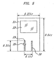
- Fig. 5 is a diagram showing a concrete structural example of the antenna device of Fig. 4.
- any component parts corresponding to those in Fig. 4 are denoted by like reference numerals or symbols, and a repeated explanation thereof will be omitted below.
- the substrate 21 is so sized as to have a horizontal length of 0.27 ⁇ r and a vertical length of 0.5 ⁇ r, where ⁇ r denotes the wavelength of a communication radio wave.
- a notch antenna 23 is formed of a linear slit cut in a length of 0.2 ⁇ r from one edge of the substrate 1.
- a notch antenna 24 operating through electromagnetic coupling with the notch antenna 23 is formed of another slit cut at a position spaced apart from the notch antenna 23 rightward by a distance of 0.1 ⁇ r and in parallel with the notch antenna 23.
- the slit of the notch antenna 24 is formed to be slightly shorter than 0.2 ⁇ r which is the length of the notch antenna 23.
- the notch antenna 24 operating through electromagnetic coupling is adjusted, by its dimension parameters, in a manner to tune with the notch antenna 23 having a feeder 25.
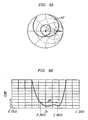
- Fig. 6A is a Smith chart representing the impedance characteristic of the antenna device
- Fig. 6B graphically shows the voltage standing wave ratio (VSWR) characteristic that indicates the impedance matching of the antenna device.
- VSWR voltage standing wave ratio
- a locus m2 expressing the impedance characteristic of the antenna device is an ⁇ type which concentrates on the center O of the Smith chart, thereby signifying that the impedance characteristic of the antenna device is rendered adequate for a wider band.
- the ordinate indicates the value of VSWR which becomes greater upward. This signifies that the impedance matching is enhanced as the value of VSWR is smaller.
- the maximum VSWR is 3.0 in a band width BW of 0.94f0 to 1.06f0. This indicates that the radiation efficiency is deteriorated 14% by the loss derived from the impedance mismatching with at least the radio circuit 22. That is, according to this antenna device, the radiation efficiency thereof is improved 22% in comparison with the conventional antenna device explained with reference to Fig. 2 where the radiation efficiency is 36%.
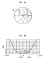
- FIGs. 7A, 7B, 8A and 8B an explanation will be given on the input impedance characteristic of the mobile telephone, which is equipped with the antenna device of Fig. 5, in case the telephone is held by a hand.
- Each of Figs. 7A and 8A is a Smith chart representing the impedance characteristic of the antenna device, and each of Figs. 7B and 8B graphically shows the voltage standing wave ratio (VSWR) characteristic that indicates the impedance matching of the antenna device.
- VSWR voltage standing wave ratio
- Figs. 7A and 7B represent the impedance characteristic of the antenna device obtained when the upper halves of the slits of the notch antennas 23 and 24 are covered with a hand.
- a locus m3 expressing the impedance characteristic of the antenna device is an ⁇ type which concentrates on the center O of the Smith chart, thereby signifying that the antenna device has a wide-band characteristic.
- the VSWR of the antenna device is less than 1.8 in a band width BW of 0.94f0 to 1.06f0, hence signifying that a stable impedance characteristic is attained.
- Figs. 8A and 8B graphically show the impedance characteristic obtained when the slits of the notch antennas 23 and 24 are entirely covered with a hand.
- a locus m4 expressing the impedance characteristic of the antenna device concentrates on the vicinity of the center O of the Smith chart, thereby signifying that the wide-band characteristic of the antenna device is still maintained.
- the VSWR of the antenna device is less than 2.2 in a band width BW of 0.94f0 to 1.06f0, hence signifying that a stable impedance characteristic is attained.
- the notch antenna 24 operating through electromagnetic coupling is adjusted by its dimension parameters in a manner to be capable of tuning, despite the disturbance or influence of a hand, with the notch antenna 23 having the feeder 25, so that a stable wide-band impedance characteristic can be attained.
- a notch antenna 23 having a feeder 25 is formed in the shape of L as its slit is bent leftward in the diagram at a position (point P1) of a predetermined length from an open end 23a on one edge of a substrate 21 and is cut from the point P1 to a predetermined position (end point).
- Another notch antenna 24 operating through electromagnetic coupling with the notch antenna 23 is formed in the shape of L as its slit is bent rightward in the diagram at a position (point P2) of a predetermined length from an open end 24a of one edge of the substrate 21 and is cut from the point P2 to a predetermined position (end point).
- a total length including the length from the open end 23a of the substrate 21 to the point P1 and the length from the point P1 to the end point is set to ⁇ /4.
- a total length including the length from the open end 24a of the substrate 21 to the point P2 and the length from the point P2 to the end point is set to be slightly shorter than ⁇ /4. Therefore, it becomes possible to shorten the slit length in the longitudinal direction of the substrate 21 (i.e., from the open ends 23a, 24a of the substrate 21 to the points P1, P2), so that the antenna device of Fig. 9 composed of the notch antennas 23 and 24 can be down-sized in comparison with the antenna device of Fig. 4.
- each slit of the notch antennas 23 and 24 is shaped into L in Fig. 9, it may be a meander or zigzag as well.
- a notch antenna operating through electromagnetic coupling with a notch antenna 23 is composed of two notch antennas 24-1 and 24-2 which are formed of two linear slits each having a predetermined length from one edge of a substrate 21.
- the notch antenna 24-1 is formed at a position spaced apart rightward by a predetermined distance from the notch antenna 23 and has a length slightly greater than ⁇ /4 from an open end 24-1a.
- the notch antenna 24-2 is formed at a position spaced apart rightward by a predetermined distance from the notch antenna 24-1 and has a length slightly shorter than ⁇ /4.
- a plurality of notch antennas operating through electromagnetic coupling are so formed as to have mutually different lengths, whereby the whole resonance band can be widened as compared with that obtained in the case of a single notch antenna.
- the resonance of antennas is expressed as ( ⁇ /4) ⁇ N (number of antennas), so that multi-resonance can be achieved by the notch antennas 24-1 and 24-2 at a desired frequency different from that of the notch antenna 23 having the feeder 25.
- Fig. 10 shows merely two notch antennas 24-1 and 24-2 operating through electromagnetic coupling, the number thereof may be three or more. Further, although the notch antenna 23 is disposed on the left side while the notch antennas 24-1 and 24-2 are disposed on the right side, the disposition thereof may be reverse as well, and the arrangement does not matter.
- metallic conductor members 31a and 31b connected to a substrate 21 are disposed proximate to each other in the vicinity of an open end 23a of a notch antenna 23 and an open end 24a of another notch antenna 24 on the substrate 21.
- the metallic conductor members 31a and 31b may be composed of the substrate 21.
- This structure can be recognized as to oppose the metallic conductor members 31a and 31b to each other via an open end 31c, or can be recognized as to connect the open end 23a and the open end 23b to the open end 31c which is used as a common open end.
- Fig. 12 is a diagram showing the electric distribution on the surface of the substrate in the antenna device of Fig. 11.
- the entire distribution can be divided into, for example, an extent e0 where almost none of high-frequency currents is distributed, an extent e1 where high-frequency currents are not distributed much, an extent e2 where high-frequency currents are distributed moderately, and an extent e3 where high-frequency currents are distributed concentratively.
- an extent e0 where almost none of high-frequency currents is distributed
- an extent e1 where high-frequency currents are not distributed much
- an extent e2 where high-frequency currents are distributed moderately
- an extent e3 where high-frequency currents are distributed concentratively.
- the open end 24a of the notch antenna 24 operating through electromagnetic coupling is connected to the common open end 31c together with the open end 23a of the notch antenna 23 having the feeder 25, whereby the high-frequency currents are dispersed in the two antennas (notch antennas 23 and 24). Consequently, even if one notch antenna 23 is affected by some disturbance such as touch of a human body for example, another notch antenna 24 is existent and therefore the input impedance characteristic is not varied with ease to eventually attain stability in the impedance characteristic.
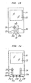
- a metallic member 41 is interposed between a notch antenna 23 and a notch antenna 24 on one side of a substrate 21 where an open end 23a of the notch antenna 23 and an open end 24a of the notch antenna 24 are formed.
- the metallic member 41 may be a dielectric member or a magnetic member without being limited to metal alone if it is effective to weaken the electric field.
- portions of a substrate 21 are extended as substrates 21a and 21b on one side thereof where an open end 23a of a notch antenna 23 and an open end 24a of a notch antenna 24 are formed, and the substrates 21a and 21b are proximate to each other.
- concentrated constant elements 51a, 51b and 51c consisting of capacitors, conductors or the like are disposed on the mutually proximate substrates 21a and 21b.
- the center concentrated constant element 51b out of such concentrated constant elements 51a, 51b and 51c consists of a capacitor while the other concentrated constant elements 51a and 51c consist of conductors, and the intensity of the electromagnetic coupling can be adjusted by changing the capacitance C of the concentrated constant element 51b which consists of a capacitor.
- the antenna characteristic is adjustable by providing the concentrated constant elements in portions of the substrate 21 as well as by changing the slit dimensions of the notch antennas or the distance between the notch antennas.
- a phaser 61 having a desired reactance component is provided at a position of the notch antenna 24 included in the antenna device of Fig. 4 and operating through electromagnetic coupling. Since the intensity of the electromagnetic coupling is adaptively changeable by the phaser 61 in this antenna device of Fig. 15, it is possible to set the intensity of the electromagnetic coupling to an optimal value thereof when the optimal value of such intensity varies depending on whether the mobile terminal using this antenna device is held or not by the user's hand for example.
- the antenna characteristic inclusive of the impedance and the radiation pattern can be adjusted as desired by means of the phaser 61 connected to the notch antenna 24 which operates through electromagnetic coupling. Moreover, since the phaser 61 is capable of changing the phase quantity to a desired value, the antenna characteristic is adjusted actively in accordance with the communication environment.
- the notch antenna operating through electromagnetic coupling is formed on one substrate where another notch antenna having a feeder is formed, in a manner to generate the same main polarization, and the relationship between such notch antennas is adjusted with regard to the shapes of slits and the distance therebetween, or a metallic member, a concentrated constant element or a phaser is additionally provided therein, so that the input impedance characteristic of the antenna device can be rendered adequate for a wider band, i.e., for attaining multi-resonance.
- a notch antenna 23 having a feeder 25 is disposed at some other position than a substrate 21 where a notch antenna 23 is formed.
- a linear antenna 71 is used as an antenna operating through electromagnetic coupling with a notch antenna 23 having a feeder 25.
- the antenna 71 operating through electromagnetic coupling with the notch antenna 23 has a length of ⁇ /2 and is disposed in the vicinity of an open end 23a of the notch antenna 23.
- This linear antenna 71 is positioned orthogonally to a slit of the notch antenna 23 in such a manner that the main polarization thereof becomes directionally coincident with that of the notch antenna 23.
- the main polarization direction of the notch antenna 23 is transverse to its slit (i.e., horizontal in the diagram)
- the main polarization direction h (i.e., longitudinal) of the linear antenna 71 can be rendered coincident (parallel) with the main polarization direction of the notch antenna 23.
- the main polarization direction h of the linear antenna 71 is almost vertical to the ground during communication to consequently become coincident with the vertical polarization direction of the base station for the mobile telephone, so that the gain tends to be greater.
- the linear antenna 71 is shaped into a straight line, but it may be a meander, zigzag or helical as well.
- a folded antenna 81 shaped by looping an antenna of a length ⁇ .
- the folded antenna 81 also is so disposed as to be coincident with the main polarization direction h. Therefore, the same advantageous effect is achievable as in the linear antenna 71 of Fig. 16.
- the fold-back distance e of the folded antenna 81 orthogonal to the main polarization direction h is set to be extremely small.
- the antenna operating through electromagnetic coupling is so disposed that the main polarization direction thereof becomes coincident with that of the notch antenna 23 having the feeder 25 in the vicinity thereof, whereby the same advantageous effect can be achieved as in the antenna device shown in Fig. 4.
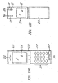
- Figs. 18A and 18B, 19A and 19B, and 20A to 20C an explanation will be given on some cases of applying the above-described antenna device to a mobile telephone. It is to be supposed that, in the description below, the antenna device shown in Fig. 4 is employed in a mobile telephone.
- a mobile telephone 201 comprises an upper body 211 having a display 214 and a speaker 215, a lower body 212 having a manual control 216 and a microphone 217, and a hinge 213 for joining the upper body 211 and the lower body 212 to each other.
- the hinge 213 is simplified in Figs. 18A and 19A, the upper body 211 and the lower body 212 are supported by the hinge 213 in a manner to be rotatable.
- Figs. 18B and 19B are diagrams each showing a structural example of an internal substrate in the mobile telephone 201 of Figs. 18A and 19A.
- any component parts corresponding to those in Fig. 4 are denoted by like reference numerals or symbols, and a repeated explanation thereof will be omitted below.
- a substrate 21a with an antenna device formed thereon is housed in the lower body 212 in such a manner that notch antennas 23 and 24 are disposed in the lowermost portion of the mobile telephone 201, and a substrate 21b without any antenna device is housed in the upper body 211 of the mobile telephone 201, whereby the notch antennas 23 and 24 (particularly an open end 23a of the notch antenna 23 and an open end 24a of the notch antenna 24) are positioned under the head to consequently reduce the harmful influence that may otherwise be derived from the head and exerted to the antenna characteristic.
- a substrate 21a with an antenna device formed thereon is housed in the upper body 211 in such a manner that notch antennas 23 and 24 are disposed in the uppermost portion of the mobile telephone 201, and a substrate 21b without any antenna device is housed in the lower body 212 of the mobile telephone 201, hence reducing the harmful influence that may otherwise be exerted to the antenna characteristic from the user's hand which holds the mobile telephone 201.
- antenna devices may be provided in both of the upper body 211 and the lower body 212.
- an optimal antenna characteristic can be attained in compliance with the communication environment by selectively switching the antenna devices in the upper body 211 and the lower body 212 or by combining the signals received in the two antenna devices.
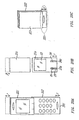
- Fig. 20A shows an example where the upper body 211 and the lower body 212 of the mobile telephone 201 of Fig. 18A is replaced with an upper body 221 and a lower body 222 respectively.
- the upper body 221 is shaped to be shorter than the lower body 222 by a predetermined length r, and in conformity therewith, as shown in Fig. 20B, a substrate 21c having no antenna device and housed in the upper body 221 is formed to be shorter by the predetermined length r than a substrate 21a having an antenna device formed thereon and housed in the lower body 222.
- a lower portion 231 of the lower body 222 is not superposed on the upper body 221 and projects downward. Consequently, an open end 23a of the notch antenna 23 and an open end 24a of the notch antenna 24 shown in Fig. 20B are not superposed on (not opposed to) another substrate 21c and project downward.
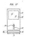
- FIG. 21 an explanation will be given on a structural example of another antenna device employed in a foldable type mobile telephone 201 where an upper body 211 and a lower body 212 are rotatable.
- any component parts corresponding to those in Fig. 4 are denoted by like reference numerals or symbols, and a repeated explanation thereof will be omitted below.
- a substrate 21 is housed in an upper body 211 of a mobile telephone 201, and a substrate 301 is housed in a lower body 212 of the mobile telephone 201.
- the upper body 211 and the lower body 212 of the mobile telephone 201 are in an open state.
- a notch antenna 302 operating through electromagnetic coupling with a notch antenna 23 is formed in a length slightly shorter than ⁇ /4 from an open end 302a at one edge thereof facing to the substrate 21. Therefore, the open end 302a of the notch antenna 302 on the substrate 301 is disposed in the vicinity of an open end 23a of the notch antenna 23 on the substrate 21.
- These two antennas are cut in the same direction (to form parallel slits), so that the directions of the main polarization can be rendered the same (parallel).
- Fig. 22 is a diagram showing another state where, in the mobile telephone 201 employing the antenna device of Fig. 21, the substrate 21 and the substrate 301 are rotated on the hinge 213 (Fig. 19A), and the lower body 212 housing the substrate 301 therein is joined to the upper body 211 housing the substrate 21 in a manner to be folded back inward as indicated by an arrow P.
- the open end 302a of the notch antenna 302 is positioned in the vicinity of the open end 23a of the notch antenna 23. Consequently, a wide-band characteristic can be attained even in case the mobile telephone is folded, as well as in the case where the upper and lower bodies thereof are open.
- the antenna is provided in the vicinity of the open end of the notch antenna with a feeder in such a manner as to generate the same main polarization, whereby the same advantageous effect is achievable as in the aforementioned antenna device of Fig. 16.
- the antenna operating through electromagnetic coupling is provided in the vicinity of the open end of the notch antenna with a feeder so as to generate the same main polarization, hence achieving a wide-band or multi-resonance input impedance characteristic of the antenna device.
- the description given above is concerned with an exemplary case of applying the present invention to a mobile telephone.
- the present invention is applicable also to some other mobile radio communication terminal having an antenna device, such as PDA (Personal Digital Assistance) or the like.
- the present invention it is possible to improve the performance of the antenna device. Moreover, the present invention ensures a stable impedance characteristic. And further according to the present invention, a wide-band characteristic can be realized.
Landscapes
- Engineering & Computer Science (AREA)
- Computer Networks & Wireless Communication (AREA)
- Support Of Aerials (AREA)
- Telephone Set Structure (AREA)
- Waveguide Aerials (AREA)
- Details Of Aerials (AREA)
Claims (2)
- Tragbares Funkkommunikationsgerät aufweisend:einen ersten Körper (211),einen zweiten Körper (212), der schwenkbar mit dem ersten Körper verbunden ist und aufmachbar und schließbar in Bezug auf den ersten Körper ist;ein erstes Substrat (21), das in dem ersten Körper beherbergt ist;eine erste schlitzförmige Nuterantenne (23), die auf dem ersten Substrat ausgebildet ist und eine Einspeisung hat;ein zweites Substrat (301), das in dem zweiten Körper beherbergt ist,und gekennzeichnet durch;eine zweite schlitzförmige Nutenantenne (302), die auf dem zweiten Substrat ausgebildet ist, in der Nähe eines offenen Endes der ersten Nutenantenne in einer solchen Weise positioniert ist, dass die Richtung der Hauptpolarisierung der zweiten Nutenantenne mit der von der ersten Antenne übereinstimmend wird, und die zweite Nutenantenne durch eine elektromagnetische Kopplung mit der ersten Antenne arbeitet, wenn erster und zweiter Körper in einem offenen Zustand und in einem geschlossenen Zustand sind.
- Tragbares Funkkommunikationsgerät nach Anspruch 1, wobei die zweite Nutenantenne parallel zu der ersten Nutenantenne in einer solchen Weise ausgebildet ist, dass die Richtung ihrer Hauptpolarisation mit der von der ersten Nutenantenne übereinstimmend wird.
Applications Claiming Priority (3)
| Application Number | Priority Date | Filing Date | Title |
|---|---|---|---|
| JP2002210557A JP3844717B2 (ja) | 2002-07-19 | 2002-07-19 | アンテナ装置および携帯無線通信端末 |
| JP2002210557 | 2002-07-19 | ||
| PCT/JP2003/008693 WO2004010533A1 (ja) | 2002-07-19 | 2003-07-09 | アンテナ装置および携帯無線通信端末 |
Publications (3)
| Publication Number | Publication Date |
|---|---|
| EP1524723A1 EP1524723A1 (de) | 2005-04-20 |
| EP1524723A4 EP1524723A4 (de) | 2005-08-24 |
| EP1524723B1 true EP1524723B1 (de) | 2007-04-18 |
Family
ID=30767735
Family Applications (1)
| Application Number | Title | Priority Date | Filing Date |
|---|---|---|---|
| EP03741290A Expired - Lifetime EP1524723B1 (de) | 2002-07-19 | 2003-07-09 | Antenneneinrichtung und tragbares funkkommunikationsendgerät |
Country Status (8)
| Country | Link |
|---|---|
| US (1) | US7053848B2 (de) |
| EP (1) | EP1524723B1 (de) |
| JP (1) | JP3844717B2 (de) |
| KR (1) | KR101025680B1 (de) |
| CN (1) | CN100375335C (de) |
| DE (1) | DE60313326T2 (de) |
| ES (1) | ES2283793T3 (de) |
| WO (1) | WO2004010533A1 (de) |
Families Citing this family (52)
| Publication number | Priority date | Publication date | Assignee | Title |
|---|---|---|---|---|
| CN1961455A (zh) * | 2004-05-27 | 2007-05-09 | 皇家飞利浦电子股份有限公司 | 包含用于交换无线电频率信号的天线的装置 |
| JP4268585B2 (ja) * | 2004-12-20 | 2009-05-27 | アルプス電気株式会社 | アンテナ装置 |
| JP2006325133A (ja) * | 2005-05-20 | 2006-11-30 | Matsushita Electric Ind Co Ltd | 放送用受信機付き携帯電話 |
| JP5088689B2 (ja) | 2005-11-18 | 2012-12-05 | 日本電気株式会社 | スロットアンテナ及び携帯無線端末 |
| US7518564B2 (en) * | 2006-05-24 | 2009-04-14 | Twisthink, L.L.C. | Slot antenna |
| US7456798B2 (en) | 2006-06-28 | 2008-11-25 | Freescale Semiconductor, Inc | Stacked loop antenna |
| WO2008026587A1 (en) * | 2006-09-01 | 2008-03-06 | Fujikura Ltd. | Antenna and electronic device |
| CN101197464B (zh) * | 2006-12-05 | 2012-11-21 | 松下电器产业株式会社 | 天线装置和无线通信装置 |
| JP4904197B2 (ja) * | 2007-05-08 | 2012-03-28 | パナソニック株式会社 | 不平衡給電広帯域スロットアンテナ |
| US20100225544A1 (en) * | 2007-05-16 | 2010-09-09 | Toru Taura | Slot antenna and portable wireless terminal |
| US20090051614A1 (en) * | 2007-08-20 | 2009-02-26 | Hang Wong | Folded dipole antenna |
| US8098756B2 (en) | 2008-05-22 | 2012-01-17 | Panasonic Corporation | MIMO antenna apparatus capable of diversity reception using one radiating conductor |
| JP2010062976A (ja) | 2008-09-05 | 2010-03-18 | Sony Ericsson Mobile Communications Ab | ノッチアンテナおよび無線装置 |
| TWI411159B (zh) * | 2009-03-11 | 2013-10-01 | Acer Inc | 一種具有降低接地面效應之行動通訊天線 |
| TWI393291B (zh) * | 2009-03-27 | 2013-04-11 | Acer Inc | 一種單極槽孔天線 |
| JP5477377B2 (ja) | 2009-03-30 | 2014-04-23 | 日本電気株式会社 | スロットアンテナ、電子機器及びスロットアンテナ製造方法 |
| CN101610310B (zh) * | 2009-07-07 | 2013-05-15 | 惠州Tcl移动通信有限公司 | 一种移动通讯终端 |
| GB0921811D0 (en) * | 2009-12-14 | 2010-01-27 | Aerial Res Technology Ltd | Notch antenna |
| JP5314610B2 (ja) * | 2010-02-01 | 2013-10-16 | 日立電線株式会社 | 複合アンテナ装置 |
| US8570225B2 (en) * | 2010-03-25 | 2013-10-29 | Sony Corporation | Antenna device and mobile device |
| US8872702B2 (en) * | 2010-04-23 | 2014-10-28 | Psion Inc. | Tuneable PCB antenna |
| JP5699820B2 (ja) * | 2010-09-16 | 2015-04-15 | 日本電気株式会社 | アンテナ装置 |
| JP5644397B2 (ja) * | 2010-11-11 | 2014-12-24 | 富士通株式会社 | 無線装置及びアンテナ装置 |
| JP2012205171A (ja) * | 2011-03-28 | 2012-10-22 | Kyocera Corp | 携帯電子機器 |
| JP2012227850A (ja) * | 2011-04-22 | 2012-11-15 | Panasonic Corp | 携帯無線端末 |
| US8779999B2 (en) * | 2011-09-30 | 2014-07-15 | Google Inc. | Antennas for computers with conductive chassis |
| US9036358B2 (en) * | 2011-12-27 | 2015-05-19 | Sony Corporation | Terminal device and transparent substrate |
| JP2013138296A (ja) * | 2011-12-28 | 2013-07-11 | Mitsumi Electric Co Ltd | アンテナ装置 |
| WO2013124897A1 (ja) | 2012-02-23 | 2013-08-29 | 日本電気株式会社 | アンテナ装置 |
| US9716307B2 (en) * | 2012-11-08 | 2017-07-25 | Htc Corporation | Mobile device and antenna structure |
| US9077087B2 (en) | 2013-02-22 | 2015-07-07 | Hong Kong Science and Technology Research Institute Co., Ltd. | Antennas using over-coupling for wide-band operation |
| KR102060733B1 (ko) | 2013-02-25 | 2019-12-30 | 삼성전자주식회사 | 유연성 기능영역을 포함한 디스플레이 소자 또는 디스플레이 조립체용 안테나 장치를 구비하는 휴대용 단말기 |
| ES2657405T3 (es) | 2013-08-09 | 2018-03-05 | Huawei Device (Dongguan) Co., Ltd. | Antena y terminal de placa de circuito impreso |
| KR102094754B1 (ko) | 2013-12-03 | 2020-03-30 | 엘지전자 주식회사 | 이동 단말기 |
| US9379445B2 (en) | 2014-02-14 | 2016-06-28 | Apple Inc. | Electronic device with satellite navigation system slot antennas |
| US9583838B2 (en) | 2014-03-20 | 2017-02-28 | Apple Inc. | Electronic device with indirectly fed slot antennas |
| US9559425B2 (en) * | 2014-03-20 | 2017-01-31 | Apple Inc. | Electronic device with slot antenna and proximity sensor |
| US9728858B2 (en) | 2014-04-24 | 2017-08-08 | Apple Inc. | Electronic devices with hybrid antennas |
| EP3016201B1 (de) * | 2014-10-29 | 2021-09-08 | Gigaset Communications GmbH | Antennenvorrichtung |
| US10103440B2 (en) | 2014-11-06 | 2018-10-16 | Sony Mobile Communications Inc. | Stripline coupled antenna with periodic slots for wireless electronic devices |
| US10218052B2 (en) | 2015-05-12 | 2019-02-26 | Apple Inc. | Electronic device with tunable hybrid antennas |
| EP3291373B1 (de) * | 2015-05-28 | 2019-12-11 | Huawei Technologies Co., Ltd. | Schlitzantenne und elektronische vorrichtung |
| CN106537690A (zh) * | 2015-08-31 | 2017-03-22 | 华为技术有限公司 | 一种缝隙天线和终端设备 |
| US10490881B2 (en) | 2016-03-10 | 2019-11-26 | Apple Inc. | Tuning circuits for hybrid electronic device antennas |
| WO2018028486A1 (en) * | 2016-08-08 | 2018-02-15 | Guangdong Oppo Mobile Telecommunications Corp., Ltd. | Housing, method for manufacturing housing, and mobile terminal having housing |
| WO2018028372A1 (en) | 2016-08-08 | 2018-02-15 | Guangdong Oppo Mobile Telecommunications Corp., Ltd. | Housing, method for manufacturing housing, and mobile terminal having housing |
| CN106102389B (zh) * | 2016-08-16 | 2018-05-29 | 广东欧珀移动通信有限公司 | 一种壳体的加工方法、壳体和移动终端 |
| US10290946B2 (en) | 2016-09-23 | 2019-05-14 | Apple Inc. | Hybrid electronic device antennas having parasitic resonating elements |
| KR102508922B1 (ko) | 2016-11-07 | 2023-03-13 | 삼성전자주식회사 | 안테나를 포함하는 전자 장치 |
| US11252268B2 (en) | 2019-11-14 | 2022-02-15 | Samsung Electronics Co., Ltd. | Electronic device including antenna |
| KR102394616B1 (ko) * | 2019-11-29 | 2022-05-06 | 주식회사 아모센스 | 안테나 모듈 |
| CN113839200A (zh) * | 2021-10-09 | 2021-12-24 | 北京悦米科技有限公司 | 一种克服手握影响、受环境影响小的天线 |
Family Cites Families (25)
| Publication number | Priority date | Publication date | Assignee | Title |
|---|---|---|---|---|
| US278151A (en) * | 1883-05-22 | Geoege s | ||
| US2781512A (en) * | 1951-12-05 | 1957-02-12 | Jr Ralph O Robinson | Cylindrical notch antenna |
| GB2220303A (en) * | 1988-06-29 | 1990-01-04 | Philips Electronic Associated | Dual polarised phased array antenna |
| JPH02218203A (ja) | 1989-02-20 | 1990-08-30 | Rajiaru Antenna Kenkyusho:Kk | 移動体通信用平面型アンテナ |
| JP3283046B2 (ja) * | 1991-10-04 | 2002-05-20 | 尚久 後藤 | ダイバーシチアンテナ |
| US5220330A (en) | 1991-11-04 | 1993-06-15 | Hughes Aircraft Company | Broadband conformal inclined slotline antenna array |
| SE500477C2 (sv) | 1992-11-20 | 1994-07-04 | Jan Peter Edward Cassel | Y-antenn |
| JP3203443B2 (ja) | 1992-12-08 | 2001-08-27 | 北陽製紙株式会社 | ハニカムコアを用いたパネルの製造方法 |
| JP2618584B2 (ja) * | 1993-04-28 | 1997-06-11 | 明星電気株式会社 | サブノッチ付円偏波クロスノッチアンテナ |
| JP2592128Y2 (ja) * | 1993-06-16 | 1999-03-17 | 京セラ株式会社 | 平型アンテナ |
| JPH07111418A (ja) | 1993-10-12 | 1995-04-25 | Matsushita Electric Works Ltd | 偏波ダイバーシティ用平面アンテナ |
| JPH0865368A (ja) | 1994-08-26 | 1996-03-08 | Hitachi Ltd | 携帯用無線電話機 |
| JPH0897760A (ja) | 1994-09-27 | 1996-04-12 | Mitsubishi Electric Corp | 携帯無線機用アンテナ装置 |
| JP3286882B2 (ja) | 1995-06-22 | 2002-05-27 | 三菱電機株式会社 | アンテナ装置 |
| DE69628392T2 (de) * | 1995-11-29 | 2004-03-11 | Ntt Mobile Communications Network Inc. | Antenne mit zwei Resonanzfrequenzen |
| JPH09270618A (ja) * | 1996-03-29 | 1997-10-14 | Mitsubishi Electric Corp | アンテナ装置 |
| SE511295C2 (sv) * | 1997-04-30 | 1999-09-06 | Moteco Ab | Antenn för radiokommunikationsapparat |
| US6043786A (en) * | 1997-05-09 | 2000-03-28 | Motorola, Inc. | Multi-band slot antenna structure and method |
| US6343208B1 (en) * | 1998-12-16 | 2002-01-29 | Telefonaktiebolaget Lm Ericsson (Publ) | Printed multi-band patch antenna |
| JP2000196344A (ja) * | 1998-12-25 | 2000-07-14 | Toshiba Corp | アンテナ装置 |
| CN1357161A (zh) * | 2000-04-20 | 2002-07-03 | 三菱电机株式会社 | 便携式无线机 |
| US6424300B1 (en) * | 2000-10-27 | 2002-07-23 | Telefonaktiebolaget L.M. Ericsson | Notch antennas and wireless communicators incorporating same |
| US6448933B1 (en) * | 2001-04-11 | 2002-09-10 | Tyco Electronics Logisitics Ag | Polarization and spatial diversity antenna assembly for wireless communication devices |
| JP2003069441A (ja) | 2001-08-23 | 2003-03-07 | Nec Saitama Ltd | 折り畳み型携帯無線機 |
| US6879849B2 (en) * | 2002-02-21 | 2005-04-12 | Telefonaktiebolaget L M Ericsson (Publ) | In-built antenna for mobile communication device |
-
2002
- 2002-07-19 JP JP2002210557A patent/JP3844717B2/ja not_active Expired - Fee Related
-
2003
- 2003-07-09 EP EP03741290A patent/EP1524723B1/de not_active Expired - Lifetime
- 2003-07-09 CN CNB038010968A patent/CN100375335C/zh not_active Expired - Fee Related
- 2003-07-09 US US10/489,898 patent/US7053848B2/en not_active Expired - Fee Related
- 2003-07-09 KR KR1020047003823A patent/KR101025680B1/ko not_active Expired - Fee Related
- 2003-07-09 WO PCT/JP2003/008693 patent/WO2004010533A1/ja not_active Ceased
- 2003-07-09 ES ES03741290T patent/ES2283793T3/es not_active Expired - Lifetime
- 2003-07-09 DE DE60313326T patent/DE60313326T2/de not_active Expired - Lifetime
Also Published As
| Publication number | Publication date |
|---|---|
| US20040239575A1 (en) | 2004-12-02 |
| EP1524723A1 (de) | 2005-04-20 |
| CN1557037A (zh) | 2004-12-22 |
| US7053848B2 (en) | 2006-05-30 |
| WO2004010533A1 (ja) | 2004-01-29 |
| DE60313326D1 (de) | 2007-05-31 |
| JP3844717B2 (ja) | 2006-11-15 |
| DE60313326T2 (de) | 2008-03-06 |
| KR20050023203A (ko) | 2005-03-09 |
| KR101025680B1 (ko) | 2011-03-30 |
| ES2283793T3 (es) | 2007-11-01 |
| CN100375335C (zh) | 2008-03-12 |
| JP2004056421A (ja) | 2004-02-19 |
| EP1524723A4 (de) | 2005-08-24 |
Similar Documents
| Publication | Publication Date | Title |
|---|---|---|
| EP1524723B1 (de) | Antenneneinrichtung und tragbares funkkommunikationsendgerät | |
| JP3503556B2 (ja) | 表面実装型アンテナおよびそのアンテナを装備した通信装置 | |
| US8212731B2 (en) | Antenna device and communication apparatus | |
| KR100477440B1 (ko) | 안테나와 이를 이용한 무선장치 | |
| US7557761B2 (en) | Array antenna apparatus having at least two feeding elements and operable in multiple frequency bands | |
| JP3562512B2 (ja) | 表面実装型アンテナおよびそのアンテナを備えた通信装置 | |
| US7760150B2 (en) | Antenna assembly and wireless unit employing it | |
| US8754820B2 (en) | Antenna apparatus provided with electromagnetic coupling adjuster and antenna element excited through multiple feeding points | |
| US7405697B2 (en) | Compact diversity antenna | |
| US6549169B1 (en) | Antenna for mobile wireless communications and portable-type wireless apparatus using the same | |
| JP3528737B2 (ja) | 表面実装型アンテナおよびその調整方法および表面実装型アンテナを備えた通信装置 | |
| US7589687B2 (en) | Antenna apparatus provided with antenna element excited through multiple feeding points | |
| JP3468201B2 (ja) | 表面実装型アンテナおよびその複共振の周波数調整設定方法および表面実装型アンテナを備えた通信装置 | |
| JP2001298313A (ja) | 表面実装型アンテナおよびそのアンテナを備えた無線機 | |
| KR20040108759A (ko) | 안테나 장치 및 무선 통신 장치 | |
| JP2006054843A (ja) | 折畳式携帯無線機 | |
| JP2000114856A (ja) | 逆fアンテナおよびそれを用いた無線装置 | |
| JP4649486B2 (ja) | 携帯端末用アンテナ | |
| JP2005303721A (ja) | アンテナ及びそれを用いた携帯無線機 | |
| JP2001136019A (ja) | 逆fアンテナおよびそれを用いた無線装置 | |
| EP1460713B1 (de) | Kompakte Diversity-Antenne | |
| US6172646B1 (en) | Antenna apparatus and communication apparatus using the antenna apparatus | |
| JP2008294635A (ja) | アンテナ装置及び携帯無線機 | |
| US20100203930A1 (en) | Short-side direction slide type radio apparatus | |
| JP2006287986A (ja) | アンテナ及びそれを用いた無線装置 |
Legal Events
| Date | Code | Title | Description |
|---|---|---|---|
| PUAI | Public reference made under article 153(3) epc to a published international application that has entered the european phase |
Free format text: ORIGINAL CODE: 0009012 |
|
| 17P | Request for examination filed |
Effective date: 20040301 |
|
| AK | Designated contracting states |
Kind code of ref document: A1 Designated state(s): AT BE BG CH CY CZ DE DK EE ES FI FR GB GR HU IE IT LI LU MC NL PT RO SE SI SK TR |
|
| A4 | Supplementary search report drawn up and despatched |
Effective date: 20050708 |
|
| RIC1 | Information provided on ipc code assigned before grant |
Ipc: 7H 01Q 13/10 A Ipc: 7H 01Q 5/00 B Ipc: 7H 01Q 1/24 B |
|
| RBV | Designated contracting states (corrected) |
Designated state(s): DE ES FR GB HU IT |
|
| 17Q | First examination report despatched |
Effective date: 20051109 |
|
| GRAP | Despatch of communication of intention to grant a patent |
Free format text: ORIGINAL CODE: EPIDOSNIGR1 |
|
| GRAS | Grant fee paid |
Free format text: ORIGINAL CODE: EPIDOSNIGR3 |
|
| GRAA | (expected) grant |
Free format text: ORIGINAL CODE: 0009210 |
|
| RAP1 | Party data changed (applicant data changed or rights of an application transferred) |
Owner name: SONY ERICSSON MOBILE COMMUNICATIONS JAPAN, INC. |
|
| AK | Designated contracting states |
Kind code of ref document: B1 Designated state(s): DE ES FR GB HU IT |
|
| REF | Corresponds to: |
Ref document number: 60313326 Country of ref document: DE Date of ref document: 20070531 Kind code of ref document: P |
|
| REG | Reference to a national code |
Ref country code: HU Ref legal event code: AG4A Ref document number: E001746 Country of ref document: HU |
|
| ET | Fr: translation filed | ||
| REG | Reference to a national code |
Ref country code: ES Ref legal event code: FG2A Ref document number: 2283793 Country of ref document: ES Kind code of ref document: T3 |
|
| PLBE | No opposition filed within time limit |
Free format text: ORIGINAL CODE: 0009261 |
|
| STAA | Information on the status of an ep patent application or granted ep patent |
Free format text: STATUS: NO OPPOSITION FILED WITHIN TIME LIMIT |
|
| 26N | No opposition filed |
Effective date: 20080121 |
|
| PGFP | Annual fee paid to national office [announced via postgrant information from national office to epo] |
Ref country code: HU Payment date: 20100812 Year of fee payment: 8 |
|
| PGFP | Annual fee paid to national office [announced via postgrant information from national office to epo] |
Ref country code: IT Payment date: 20100723 Year of fee payment: 8 |
|
| PG25 | Lapsed in a contracting state [announced via postgrant information from national office to epo] |
Ref country code: HU Free format text: LAPSE BECAUSE OF NON-PAYMENT OF DUE FEES Effective date: 20110710 |
|
| PG25 | Lapsed in a contracting state [announced via postgrant information from national office to epo] |
Ref country code: IT Free format text: LAPSE BECAUSE OF NON-PAYMENT OF DUE FEES Effective date: 20110709 |
|
| REG | Reference to a national code |
Ref country code: FR Ref legal event code: PLFP Year of fee payment: 13 |
|
| PGFP | Annual fee paid to national office [announced via postgrant information from national office to epo] |
Ref country code: FR Payment date: 20150626 Year of fee payment: 13 |
|
| PGFP | Annual fee paid to national office [announced via postgrant information from national office to epo] |
Ref country code: ES Payment date: 20150728 Year of fee payment: 13 Ref country code: DE Payment date: 20150721 Year of fee payment: 13 Ref country code: GB Payment date: 20150721 Year of fee payment: 13 |
|
| REG | Reference to a national code |
Ref country code: DE Ref legal event code: R119 Ref document number: 60313326 Country of ref document: DE |
|
| GBPC | Gb: european patent ceased through non-payment of renewal fee |
Effective date: 20160709 |
|
| PG25 | Lapsed in a contracting state [announced via postgrant information from national office to epo] |
Ref country code: DE Free format text: LAPSE BECAUSE OF NON-PAYMENT OF DUE FEES Effective date: 20170201 Ref country code: FR Free format text: LAPSE BECAUSE OF NON-PAYMENT OF DUE FEES Effective date: 20160801 |
|
| REG | Reference to a national code |
Ref country code: FR Ref legal event code: ST Effective date: 20170331 |
|
| PG25 | Lapsed in a contracting state [announced via postgrant information from national office to epo] |
Ref country code: GB Free format text: LAPSE BECAUSE OF NON-PAYMENT OF DUE FEES Effective date: 20160709 |
|
| PG25 | Lapsed in a contracting state [announced via postgrant information from national office to epo] |
Ref country code: ES Free format text: LAPSE BECAUSE OF NON-PAYMENT OF DUE FEES Effective date: 20160710 |
|
| REG | Reference to a national code |
Ref country code: ES Ref legal event code: FD2A Effective date: 20181130 |