EP1524075B1 - Schleifrahmen und Stativ für ein Bandschleifgerät - Google Patents
Schleifrahmen und Stativ für ein Bandschleifgerät Download PDFInfo
- Publication number
- EP1524075B1 EP1524075B1 EP04024242A EP04024242A EP1524075B1 EP 1524075 B1 EP1524075 B1 EP 1524075B1 EP 04024242 A EP04024242 A EP 04024242A EP 04024242 A EP04024242 A EP 04024242A EP 1524075 B1 EP1524075 B1 EP 1524075B1
- Authority
- EP
- European Patent Office
- Prior art keywords
- base
- sander
- rod
- sanding frame
- frame according
- Prior art date
- Legal status (The legal status is an assumption and is not a legal conclusion. Google has not performed a legal analysis and makes no representation as to the accuracy of the status listed.)
- Expired - Lifetime
Links
- 238000000034 method Methods 0.000 claims description 5
- 230000003019 stabilising effect Effects 0.000 claims 1
- 230000000712 assembly Effects 0.000 description 3
- 238000000429 assembly Methods 0.000 description 3
- 238000004519 manufacturing process Methods 0.000 description 3
- 239000002023 wood Substances 0.000 description 2
- 230000000295 complement effect Effects 0.000 description 1
Images






Classifications
-
- B—PERFORMING OPERATIONS; TRANSPORTING
- B24—GRINDING; POLISHING
- B24B—MACHINES, DEVICES, OR PROCESSES FOR GRINDING OR POLISHING; DRESSING OR CONDITIONING OF ABRADING SURFACES; FEEDING OF GRINDING, POLISHING, OR LAPPING AGENTS
- B24B21/00—Machines or devices using grinding or polishing belts; Accessories therefor
-
- B—PERFORMING OPERATIONS; TRANSPORTING
- B24—GRINDING; POLISHING
- B24B—MACHINES, DEVICES, OR PROCESSES FOR GRINDING OR POLISHING; DRESSING OR CONDITIONING OF ABRADING SURFACES; FEEDING OF GRINDING, POLISHING, OR LAPPING AGENTS
- B24B23/00—Portable grinding machines, e.g. hand-guided; Accessories therefor
- B24B23/005—Auxiliary devices used in connection with portable grinding machines, e.g. holders
-
- B—PERFORMING OPERATIONS; TRANSPORTING
- B24—GRINDING; POLISHING
- B24B—MACHINES, DEVICES, OR PROCESSES FOR GRINDING OR POLISHING; DRESSING OR CONDITIONING OF ABRADING SURFACES; FEEDING OF GRINDING, POLISHING, OR LAPPING AGENTS
- B24B23/00—Portable grinding machines, e.g. hand-guided; Accessories therefor
- B24B23/06—Portable grinding machines, e.g. hand-guided; Accessories therefor with abrasive belts, e.g. with endless travelling belts; Accessories therefor
Definitions
- the present invention generally relates to electric powered portable sanders. More particularly it relates to a sander frame according to claim 1 and to a method of converting same into a stand for a portable sander according to claim 13.
- a belt sander may be employed with either a sanding frame/shoe or an inversion stand.
- Sanding frames are generally well known. Sander frames are used to expand the footprint or base of the sander on the workpiece below. When a belt sander is mounted in such a frame, the sander is stabilised for movement over the surface of the workpiece. If the user applies uneven or unbalanced levels of force to the sander's handle(s) then the frame/shoe will prevent the sander from tipping and/or gouging the work piece surface. Additionally, many sanding frames contain means for adjusting the depth-of-cut of the sander mounted within the rigid frame. With such a mechanism the user can adjust the amount of wood removed by the sander as it is passed over the workpiece.
- Sander stands are also generally known.
- a so called “inversion stand” is an accessory that provides a fixed frame/base for holding the belt sander in an orientation on its side or inverted so that the abrasive belt is exposed for access by the user.
- the portable sander becomes a bench tool and the user can pass a piece of wood over the moving belt, or press and manipulate a workpiece against the moving belt.
- Inversion stands sometimes are provided with a table or fence to support and/or align the workpiece while it is slid over the sander belt.
- Sander stands and frames are provided as two different accessories. They add to the bulk and weight of equipment the tradesman must transport to the work site.
- the stand in particular, is intended for stationary use and current models are not very portable.
- EP0790105 describes a frame for holding a sander.
- the frame has adjustable supports such that the height and angle of the sanding belt over a workpiece can be adjusted.
- a sanding frame according to claim 1.
- An advantage of such an adaptable accessory is that the sander frame performs double duty by serving as the mounting point for the sander in both the mobile frame role and fixed stand role. Savings are achieved in cost, weight, and storage volume.
- a further advantage of the subject invention is that's since the sanding frame has a depth of cut adjustment, that capability will also be present in the fixed stand.
- a still further advantage of the subject frame/stand is the provision of a particularly economical and easy to manufacture hinge structure for pivoting adjustment of the sander within the frame, and thus of the sanders depth of cut.
- Said hinges comprising an open recess in the frame, a bearing element of simple geometry and defining a cylindrical bore, and a retainer piece for holding the bearing in the recess.
- sander frame 20 consists of a base 22 defining an opening 24. In the preferred embodiment shown both base 22 and opening 24 are substantially rectangular.
- Base 22 has a first lower surface 23 and a second upper surface 25.
- First lower surface 23 is preferably finished or coated to move smoothly over the surface of a wooden workpiece.
- a forward rod assembly 30 and a rearward rod assembly 32 are pivotally connected to the base 22 across opening 24 and proximate to their respective ends of the base.
- Forward rod assembly 30 is comprised of forward rod 31 and two hinge assemblies 40
- rear rod assembly 32 is comprised of rear rod 33 and two more hinge assemblies 40.
- mounting plate 34 Connected to and pivoting with forward rod 31 is a mounting plate 34.
- Threaded screw 36 Rotateably mounted within mounting plate 34 is threaded screw 36, which is turned by knob 38.
- a depth-of-cut adjustment mechanism 60 is mounted to frame 22 and connected to forward rod 31 for pivoting the forward rod assembly 30. Adjustment of depth of cut mechanism 60 causes forward rod 31 to pivot upward and forward and out of the plane of the base 22, or rearward and downward into the plane of the base 22.
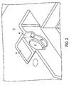
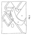
- each recess 41 is of relatively simple geometry. Preferably, it may be a simple rectangle or a semicylindrical shape or a combination thereof.
- bearing 42 In the recess 41 is located a bearing 42.
- Bearing 42 may also be of a simple external geometry selected to conform to the recess 41.
- Bearing 42 defines a bore 43.
- Rotatably mounted in bore 43 is the first or outer end 48 of pivot pin 44.
- the second or inner end 49 of pivot pin 44 is connected to a first end 50 of pivot arm 45.
- the second end 51 of each pivot arm 45 is connected to either rod 31 or 33.
- Bearing element 42 is captured in recess 41 by a retainer.
- retainer plate 46 covers the top of recess 41 and is secured to the base 22 by a machine screw 47.
- a lip 28 of the base 22 also serves to retain the bearing element 42.
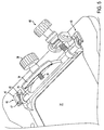
- the sander 10 (some structural elements of the sander are omitted for clarity and an improved view of the subject frame/stand) is shown mounted in frame 20.
- Sander 10 is connected to the pivotable rods 31 and 33 so that the sander can be raised or lowered relative to the base 22 for adjustment of the depth-of-cut.
- the sander housing 12 has clips 14 that clasp the rear pivot rod 33.
- a hole 16 (not shown, but the same hole used to mount the auxiliary handle in its forward optional position) receives threaded screw 36.
- Knob 38 is used to tighten screw 36 and pull housing 12 against mounting plate 34.
- Yoke 26 defines a bore 27 (not shown).
- Front rod 31 passes through a collar 62.
- a threaded rod 64 having a first end 63 and a second end 64 is attached to the collar 62 at the first end 63.
- Threaded rod 64 extends through the bore 27 of yoke 26 and is threadably engaged by a knob 68 at the second end 64.
- a biasing spring 66 is mounted co-axially around the threaded rod 64 between collar 62 and yoke 26. Spring 66 acts to push the collar 62 and thus rod 31 downward into the lowered position.
- a user can turn knob 68 to pull the collar 62 and thus the forward rod 31 upward into a raised position, against the force of spring 66.
- the sander 10 With the sander 10 connected between the forward rod 31 and the rear rod 33 (as described above), movement of the forward rod 31 is transmitted to the rear rod 33 and produces an identical pivoting movement.
- the sander 10 moves in a arcuate path that raises or lowers the sander within the opening 24 while maintaining the sander's abrasive surface 18 planar parallel with the frame base 22, and thus to the workpiece.
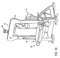
- the sander frame can be converted into an inversion stand 70 by the addition of two legs 72 and a fence assembly 80.
- the legs 72 are secured to the base 22 by screws 74.
- Legs 72 may be connected to base 22 to achieve either a vertical orientation as in Fig. 10 or a horizontal orientation as in Fig. 12, wherein base 22 is substantially perpendicular to the ground.
- legs could be used to support the base 22 in an inverted orientation substantially planar parallel relation to the ground, and wherein first/lower surface 23 and the abrasive belt face upward.
- Fence assembly 80 can be secured to base 22 by screws 83 in either of two positions complementary to the chosen orientation of the sander.
- Fence assembly 80 comprises a fixed element 82 and an angularly adjustable table 84, which may secured with nut 86 at the desired angle relative to the plane of the base 22.
- Fence assembly 80 also includes a guard piece 81.
- guard 81 is located adjacent to the abrasive belt and covers the gap between the rear of roller/belt 18 and the sander housing 12 in order to prevent a small/thin workpiece from being dragged into that gap by the movement of the belt 18.
- the table 86 is directly in the path of the belt 18 and a separate guard is not required.
- the above-described depth of cut adjustment of the sander 10 in the sander frame 20 permits the user to move the sander belt 18 towards and away from the table 84. This is particularly advantageous since the pivoting movement of the table 84 can open up a gap between the belt 18 and the table, and a small/thin work piece could be dragged into that gap by the movement of the belt.
Landscapes
- Engineering & Computer Science (AREA)
- Mechanical Engineering (AREA)
- Finish Polishing, Edge Sharpening, And Grinding By Specific Grinding Devices (AREA)
- Polishing Bodies And Polishing Tools (AREA)
- Constituent Portions Of Griding Lathes, Driving, Sensing And Control (AREA)
Claims (13)
- Schleifrahmen (20) zum Halten eines tragbaren angetriebenen Schleifgeräts (10) mit einer beweglichen Schleiffläche (18), wobei der Rahmen umfasst:eine Basis (22), die eine Öffnung (24) aufweist, wobei das Schleifgerät (10) in der Öffnung gehalten werden kann, so dass der Rahmen das Schleifgerät für eine Bewegung über ein Werkstück hält und stabilisiert;gekennzeichnet durch eine Stütze (72), die wahlweise mit der Basis zum Halten der Basis in einer Ausrichtung, in der die Ebene der Basis im Wesentlichen senkrecht ist und die Schleiffläche für einen Zugriff durch einen Benutzer freigegeben ist, verbunden werden kann.
- Schleifrahmen nach Anspruch 1, wobei die Basis eine erste Fläche (23) und eine zweite Fläche (25) hat und die Basis im Wesentlichen in einer Ebene liegt und
wobei die Stütze wahlweise mit der Basis zum Halten der Basis in einer Ausrichtung verbunden werden kann, in der die Ebene der Basis im Wesentlichen senkrecht zu dem Boden oder planparallel zu dem Boden ist. - Schleifrahmen nach Anspruch 1 oder 2, ferner mit einer schwenkbar mit der Basis verbundenen Stangenanordnung (30) zum beweglichen Halten des Schleifgeräts.
- Schleifrahmen nach Anspruch 3, ferner mit einem Schneidtiefeneinstellmechanismus (60), der mit der Basis und der Stangenanordnung verbunden ist, um die Stangenanordnung zu verschwenken.
- Schleifrahmen nach Anspruch 3 oder 4, wobei die schwenkbare Stangenordnung umfasst:eine Ausnehmung (41), die in der Basis vorgesehen ist,ein Lager (42), das in der Ausnehmung vorgesehen ist und eine Bohrung (43) aufweist,einen Schwenkstift (44) mit einem ersten Ende (48) und einem zweiten Ende (49), wobei das erste Ende drehbar in der Bohrung gehaltert ist,einen Schwenkarm (45) mit einem ersten Ende (50) und einem zweiten Ende (51), wobei das erste Ende mit dem zweiten Ende des Schwenkstifts verbunden ist,und eine Stange (31), die mit dem zweiten Ende des Schwenkarms verbunden ist.
- Schleifrahmen nach einem der Ansprüche 3 bis 5, wobei die Stange aus der Ebene der Basis verschwenkbar ist.
- Schleifrahmen nach einem der Ansprüche 3 bis 6, ferner mit einer Feder zum Vorspannen der Stange in die Ebene der Basis.
- Schleifrahmen nach einem der Ansprüche 4 bis 7, wobei der Schneidtiefenmechanismus umfasst
ein Joch (26), das mit der Basis verbunden ist und eine Bohrung aufweist,
eine Gewindestange (65) mit einem ersten Ende (63) und einem zweiten Ende (64), die sich durch die Bohrung des Jochs erstreckt,
einen Ring (62), der mit der Stangenanordnung und dem ersten Ende der Gewindestange verbunden ist, und
einen Griff (68), der in Gewindeeingriff mit der Stange steht, um die Stange durch das Joch zu ziehen. - Schleifrahmen nach Anspruch 8, wobei der Schneidtiefenmechanismus ferner eine Feder (66) umfasst, die koaxial zu der Gewindestange zwischen dem Ring und dem Joch angeordnet ist.
- Schleifrahmen nach einem der vorhergehenden Ansprüche, ferner mit einer Anschlaganordnung (80), die mit der Basis verbunden werden kann.
- Schleifrahmen nach Anspruch 10, wobei die Anschlaganordnung einen Tisch (84) umfasst, der winkelmäßig in Bezug auf die Ebene der Basis eingestellt werden kann.
- Schleifrahmen nach Anspruch 10 oder 11, wobei die Anschlaganordnung ein Schutzelement (81) umfasst, das benachbart zu der Schleiffläche angeordnet werden kann.
- Verfahren zum Überführen eines Schleifrahmens (20) in einen Halter für ein tragbares Schleifgerät (10) mit einer beweglichen Schleiffläche (18), wobei das Verfahren die folgenden Schritte umfasst:Bereitstellen eines Schleifrahmens (20) mit einer Basis, die eine Öffnung (24) zum Halten und Stabilisieren des Schleifgeräts (10) aufweist, und mit einer wahlweise verbindbaren Stütze (72),Befestigen des Schleifgeräts (10) an dem Rahmen (20),wobei das Verfahren gekennzeichnet ist durch ein Anbringen der Stütze (72) an dem Schleifrahmen (20), so dass die bewegliche Schleiffläche (18) des Schleifgeräts für einen Zugriff durch einen Benutzer freigegeben ist in einer Ausrichtung, in der die Ebene der Basis im Wesentlichen senkrecht ist.
Priority Applications (1)
| Application Number | Priority Date | Filing Date | Title |
|---|---|---|---|
| PL04024242T PL1524075T3 (pl) | 2003-10-14 | 2004-10-12 | Rama szlifierki i stanowisko dla szlifierki taśmowej |
Applications Claiming Priority (2)
| Application Number | Priority Date | Filing Date | Title |
|---|---|---|---|
| US684870 | 2003-10-14 | ||
| US10/684,870 US7207875B2 (en) | 2003-10-14 | 2003-10-14 | Sanding frame and stand for a belt sander |
Publications (2)
| Publication Number | Publication Date |
|---|---|
| EP1524075A1 EP1524075A1 (de) | 2005-04-20 |
| EP1524075B1 true EP1524075B1 (de) | 2007-06-27 |
Family
ID=34377609
Family Applications (1)
| Application Number | Title | Priority Date | Filing Date |
|---|---|---|---|
| EP04024242A Expired - Lifetime EP1524075B1 (de) | 2003-10-14 | 2004-10-12 | Schleifrahmen und Stativ für ein Bandschleifgerät |
Country Status (8)
| Country | Link |
|---|---|
| US (1) | US7207875B2 (de) |
| EP (1) | EP1524075B1 (de) |
| CN (1) | CN1607070B (de) |
| AT (1) | ATE365607T1 (de) |
| DE (1) | DE602004007211T2 (de) |
| DK (1) | DK1524075T3 (de) |
| ES (1) | ES2287622T3 (de) |
| PL (1) | PL1524075T3 (de) |
Families Citing this family (15)
| Publication number | Priority date | Publication date | Assignee | Title |
|---|---|---|---|---|
| ES2282815T3 (es) * | 2004-12-15 | 2007-10-16 | Black & Decker Inc. | Soporte para un elemento de lijar. |
| US7235005B2 (en) | 2005-03-24 | 2007-06-26 | Black & Decker Inc. | Belt sander |
| US7410412B2 (en) * | 2005-01-21 | 2008-08-12 | Black & Decker Inc. | Belt sander |
| US7837537B2 (en) | 2005-03-24 | 2010-11-23 | Black & Decker Inc. | Belt sander |
| US7347211B1 (en) * | 2005-05-03 | 2008-03-25 | Elizabeth Macklin | Electrically operated sander for removing calluses and increasing circulation |
| US8231440B2 (en) * | 2007-04-12 | 2012-07-31 | Lamarche Paul | Expansible sanding block exhibiting oblique extending surfaces |
| US8011998B2 (en) * | 2007-04-12 | 2011-09-06 | Lamarche Paul | Expansible sanding block exhibiting oblique extending surfaces |
| DE102009009936A1 (de) * | 2009-02-20 | 2010-08-26 | Metabowerke Gmbh | Elektrohandwerkzeuggerät |
| USD609725S1 (en) * | 2009-05-08 | 2010-02-09 | Roger Price | Benchtop sanding board having a cooperating slot and clamp to retain an abrasive sheet |
| CN101648367B (zh) * | 2009-06-24 | 2011-05-11 | 江苏瑞安特机械集团有限公司 | 防砂进孔装置 |
| US20110263186A1 (en) * | 2010-04-26 | 2011-10-27 | Sevedge Marvin R | Bench top vibrating sanding table |
| CN104227535B (zh) * | 2013-06-20 | 2016-10-05 | 宝钢新日铁汽车板有限公司 | 用于角向磨光机的可调节轨道打磨小车 |
| US9056384B1 (en) | 2014-01-10 | 2015-06-16 | Tacha Holdings Inc. | Apparatus and method for sanding edges of a panel |
| DE102016222043A1 (de) * | 2016-11-10 | 2018-02-22 | Bayerische Motoren Werke Aktiengesellschaft | Schleifgerät |
| IT202000032198A1 (it) * | 2020-12-23 | 2022-06-23 | Admina S R L | Levigatrice a nastro manuale |
Family Cites Families (21)
| Publication number | Priority date | Publication date | Assignee | Title |
|---|---|---|---|---|
| US814787A (en) | 1905-09-08 | 1906-03-13 | Joseph Lehnbeuter | Polishing-machine. |
| US1841787A (en) | 1930-04-28 | 1932-01-19 | Stanley Works | Sanding and polishing machine |
| US2538044A (en) | 1948-06-01 | 1951-01-16 | Elmer C Ruehle | Belt sander attachment for power tools |
| DE1277068B (de) | 1965-04-24 | 1968-09-05 | Lutz Kg Eugen | Handbandschleifmaschine |
| US3664614A (en) | 1969-11-26 | 1972-05-23 | Charles H Baechle | Power tool accessory |
| DE6946309U (de) | 1969-11-29 | 1970-05-21 | Metabowerke Kg | Handbandschleifmaschine. |
| US3828484A (en) | 1972-08-28 | 1974-08-13 | C Baechle | Power tool accessory |
| US4114665A (en) * | 1976-05-06 | 1978-09-19 | Decker Henry P | Woodworking bench for portable motor driven hand tools |
| US4085552A (en) * | 1977-03-11 | 1978-04-25 | Irvin Industries, Inc. | Work tool stand |
| US4265283A (en) | 1979-01-02 | 1981-05-05 | The Triangle Corporation | Work bench structure |
| DE2941353C2 (de) | 1979-10-12 | 1984-08-16 | Karl M. Reich Maschinenfabrik GmbH, 7440 Nürtingen | Handbandschleifmaschine mit einer Abhebeeinrichtung |
| DE7935820U1 (de) | 1979-12-20 | 1980-04-03 | Karl M. Reich, Maschinenfabrik Gmbh, 7440 Nuertingen | Fuehrungsrahmen fuer handbandschleifmaschinen |
| GB2102712B (en) * | 1981-06-08 | 1984-12-12 | Semco Engineering Limited | Machine tool which can be driven by an electrically powered hand tool |
| DE8329689U1 (de) | 1983-10-14 | 1984-01-26 | Karl M. Reich Maschinenfabrik GmbH, 7440 Nürtingen | Untergestell fuer handbandschleifmaschinen |
| DE3600882A1 (de) * | 1986-01-15 | 1987-07-16 | Helmut Ebertseder | Vorrichtung zur halterung eines ein elektromotorisch angetriebenes messer aufweisenden handhobels |
| US5092379A (en) | 1990-12-28 | 1992-03-03 | Stephen Stallings | Workstand for a hand-held electric planer |
| DE4211738C2 (de) | 1992-04-03 | 1995-04-06 | Guenther Heinrich | Vorrichtung zum stationären Betrieb motorgetriebener spanabhebender Handarbeitsgeräte |
| US5421126A (en) | 1993-12-20 | 1995-06-06 | Strege; Alan B. | Sander attachment for attaching to an existing fence |
| DE19605445C1 (de) * | 1996-02-15 | 1997-02-27 | Mai Roland Dipl Ing Fh | Vorrichtung zum Führen von Handbearbeitungsgeräten |
| DE19704088A1 (de) * | 1997-02-04 | 1998-08-06 | Bosch Gmbh Robert | Handbandschleifer |
| US6854701B2 (en) * | 2003-06-16 | 2005-02-15 | Raymond J. Brockmann | Belt sander support and orientation apparatus |
-
2003
- 2003-10-14 US US10/684,870 patent/US7207875B2/en not_active Expired - Fee Related
-
2004
- 2004-10-12 AT AT04024242T patent/ATE365607T1/de not_active IP Right Cessation
- 2004-10-12 DE DE602004007211T patent/DE602004007211T2/de not_active Expired - Lifetime
- 2004-10-12 PL PL04024242T patent/PL1524075T3/pl unknown
- 2004-10-12 ES ES04024242T patent/ES2287622T3/es not_active Expired - Lifetime
- 2004-10-12 EP EP04024242A patent/EP1524075B1/de not_active Expired - Lifetime
- 2004-10-12 DK DK04024242T patent/DK1524075T3/da active
- 2004-10-14 CN CN2004100921313A patent/CN1607070B/zh not_active Expired - Fee Related
Also Published As
| Publication number | Publication date |
|---|---|
| ES2287622T3 (es) | 2007-12-16 |
| PL1524075T3 (pl) | 2007-10-31 |
| EP1524075A1 (de) | 2005-04-20 |
| ATE365607T1 (de) | 2007-07-15 |
| DE602004007211D1 (de) | 2007-08-09 |
| US7207875B2 (en) | 2007-04-24 |
| US20050079810A1 (en) | 2005-04-14 |
| CN1607070A (zh) | 2005-04-20 |
| DK1524075T3 (da) | 2007-10-22 |
| DE602004007211T2 (de) | 2008-02-28 |
| CN1607070B (zh) | 2010-06-16 |
Similar Documents
| Publication | Publication Date | Title |
|---|---|---|
| US7207875B2 (en) | Sanding frame and stand for a belt sander | |
| US5431206A (en) | Portable workstation | |
| US6520227B2 (en) | Apparatus and method for mounting routers in tables | |
| US5494251A (en) | Artist's easel | |
| CA2317831A1 (en) | Power tool mounting stand | |
| US10207348B2 (en) | Dual position blade guide for vertical or horizontal position of band saw | |
| US4235565A (en) | Precise dowel joint woodworking device | |
| US4810137A (en) | Double-use electrical drill | |
| US7647872B2 (en) | Folding, auto-leveling extension table | |
| CA2375002C (en) | Grinding machine having adjustable mechanism | |
| CA2731602C (en) | Docking and miter saw | |
| US3952622A (en) | Vice mounted multiple-use band saw with detachable work surface | |
| JPH01146607A (ja) | 卓上フライス装置 | |
| US20030005801A1 (en) | Power tool stand accessory top with vertical adjustment and frictional engagement lock | |
| US20080268755A1 (en) | Motorized Tool and Support Table Therefore | |
| US5697411A (en) | Workpiece support apparatus | |
| CN102015177B (zh) | 用于工具机的工作台 | |
| JPH067859Y2 (ja) | スライド式卓上切断機 | |
| CN211029002U (zh) | 一种五金加工用夹具 | |
| CN222344838U (zh) | 一种机械零件加工夹具 | |
| US20060090625A1 (en) | Band saw | |
| JPH0650121Y2 (ja) | 研磨機 | |
| CN214925935U (zh) | 切割工作台折叠机架 | |
| CN220660379U (zh) | 一种钢结构型材切割机 | |
| CN220638509U (zh) | 一种石材加工用多角度固定装置 |
Legal Events
| Date | Code | Title | Description |
|---|---|---|---|
| PUAI | Public reference made under article 153(3) epc to a published international application that has entered the european phase |
Free format text: ORIGINAL CODE: 0009012 |
|
| AK | Designated contracting states |
Kind code of ref document: A1 Designated state(s): AT BE BG CH CY CZ DE DK EE ES FI FR GB GR HU IE IT LI LU MC NL PL PT RO SE SI SK TR |
|
| AX | Request for extension of the european patent |
Extension state: AL HR LT LV MK |
|
| 17P | Request for examination filed |
Effective date: 20050620 |
|
| AKX | Designation fees paid |
Designated state(s): AT BE BG CH CY CZ DE DK EE ES FI FR GB GR HU IE IT LI LU MC NL PL PT RO SE SI SK TR |
|
| GRAP | Despatch of communication of intention to grant a patent |
Free format text: ORIGINAL CODE: EPIDOSNIGR1 |
|
| GRAS | Grant fee paid |
Free format text: ORIGINAL CODE: EPIDOSNIGR3 |
|
| GRAA | (expected) grant |
Free format text: ORIGINAL CODE: 0009210 |
|
| AK | Designated contracting states |
Kind code of ref document: B1 Designated state(s): AT BE BG CH CY CZ DE DK EE ES FI FR GB GR HU IE IT LI LU MC NL PL PT RO SE SI SK TR |
|
| REG | Reference to a national code |
Ref country code: GB Ref legal event code: FG4D |
|
| REG | Reference to a national code |
Ref country code: CH Ref legal event code: EP |
|
| REG | Reference to a national code |
Ref country code: IE Ref legal event code: FG4D |
|
| REF | Corresponds to: |
Ref document number: 602004007211 Country of ref document: DE Date of ref document: 20070809 Kind code of ref document: P |
|
| REG | Reference to a national code |
Ref country code: SE Ref legal event code: TRGR |
|
| REG | Reference to a national code |
Ref country code: DK Ref legal event code: T3 |
|
| REG | Reference to a national code |
Ref country code: CH Ref legal event code: NV Representative=s name: E. BLUM & CO. AG PATENT- UND MARKENANWAELTE VSP |
|
| REG | Reference to a national code |
Ref country code: PL Ref legal event code: T3 |
|
| ET | Fr: translation filed | ||
| REG | Reference to a national code |
Ref country code: ES Ref legal event code: FG2A Ref document number: 2287622 Country of ref document: ES Kind code of ref document: T3 |
|
| PG25 | Lapsed in a contracting state [announced via postgrant information from national office to epo] |
Ref country code: BG Free format text: LAPSE BECAUSE OF FAILURE TO SUBMIT A TRANSLATION OF THE DESCRIPTION OR TO PAY THE FEE WITHIN THE PRESCRIBED TIME-LIMIT Effective date: 20070927 Ref country code: SI Free format text: LAPSE BECAUSE OF FAILURE TO SUBMIT A TRANSLATION OF THE DESCRIPTION OR TO PAY THE FEE WITHIN THE PRESCRIBED TIME-LIMIT Effective date: 20070627 Ref country code: PT Free format text: LAPSE BECAUSE OF FAILURE TO SUBMIT A TRANSLATION OF THE DESCRIPTION OR TO PAY THE FEE WITHIN THE PRESCRIBED TIME-LIMIT Effective date: 20071127 |
|
| PG25 | Lapsed in a contracting state [announced via postgrant information from national office to epo] |
Ref country code: SK Free format text: LAPSE BECAUSE OF FAILURE TO SUBMIT A TRANSLATION OF THE DESCRIPTION OR TO PAY THE FEE WITHIN THE PRESCRIBED TIME-LIMIT Effective date: 20070627 |
|
| PG25 | Lapsed in a contracting state [announced via postgrant information from national office to epo] |
Ref country code: GR Free format text: LAPSE BECAUSE OF FAILURE TO SUBMIT A TRANSLATION OF THE DESCRIPTION OR TO PAY THE FEE WITHIN THE PRESCRIBED TIME-LIMIT Effective date: 20070928 |
|
| PLBE | No opposition filed within time limit |
Free format text: ORIGINAL CODE: 0009261 |
|
| STAA | Information on the status of an ep patent application or granted ep patent |
Free format text: STATUS: NO OPPOSITION FILED WITHIN TIME LIMIT |
|
| PG25 | Lapsed in a contracting state [announced via postgrant information from national office to epo] |
Ref country code: RO Free format text: LAPSE BECAUSE OF FAILURE TO SUBMIT A TRANSLATION OF THE DESCRIPTION OR TO PAY THE FEE WITHIN THE PRESCRIBED TIME-LIMIT Effective date: 20070627 Ref country code: MC Free format text: LAPSE BECAUSE OF NON-PAYMENT OF DUE FEES Effective date: 20071031 |
|
| 26N | No opposition filed |
Effective date: 20080328 |
|
| PG25 | Lapsed in a contracting state [announced via postgrant information from national office to epo] |
Ref country code: IE Free format text: LAPSE BECAUSE OF NON-PAYMENT OF DUE FEES Effective date: 20071012 |
|
| PGFP | Annual fee paid to national office [announced via postgrant information from national office to epo] |
Ref country code: CZ Payment date: 20080926 Year of fee payment: 5 Ref country code: NL Payment date: 20081024 Year of fee payment: 5 Ref country code: PL Payment date: 20080919 Year of fee payment: 5 |
|
| PG25 | Lapsed in a contracting state [announced via postgrant information from national office to epo] |
Ref country code: EE Free format text: LAPSE BECAUSE OF FAILURE TO SUBMIT A TRANSLATION OF THE DESCRIPTION OR TO PAY THE FEE WITHIN THE PRESCRIBED TIME-LIMIT Effective date: 20070627 |
|
| PGFP | Annual fee paid to national office [announced via postgrant information from national office to epo] |
Ref country code: CH Payment date: 20081027 Year of fee payment: 5 Ref country code: DK Payment date: 20081030 Year of fee payment: 5 |
|
| PGFP | Annual fee paid to national office [announced via postgrant information from national office to epo] |
Ref country code: AT Payment date: 20080919 Year of fee payment: 5 Ref country code: ES Payment date: 20081027 Year of fee payment: 5 Ref country code: FI Payment date: 20081030 Year of fee payment: 5 |
|
| PGFP | Annual fee paid to national office [announced via postgrant information from national office to epo] |
Ref country code: SE Payment date: 20081029 Year of fee payment: 5 |
|
| PG25 | Lapsed in a contracting state [announced via postgrant information from national office to epo] |
Ref country code: CY Free format text: LAPSE BECAUSE OF FAILURE TO SUBMIT A TRANSLATION OF THE DESCRIPTION OR TO PAY THE FEE WITHIN THE PRESCRIBED TIME-LIMIT Effective date: 20070627 |
|
| PG25 | Lapsed in a contracting state [announced via postgrant information from national office to epo] |
Ref country code: LU Free format text: LAPSE BECAUSE OF NON-PAYMENT OF DUE FEES Effective date: 20071012 |
|
| PG25 | Lapsed in a contracting state [announced via postgrant information from national office to epo] |
Ref country code: TR Free format text: LAPSE BECAUSE OF FAILURE TO SUBMIT A TRANSLATION OF THE DESCRIPTION OR TO PAY THE FEE WITHIN THE PRESCRIBED TIME-LIMIT Effective date: 20070627 Ref country code: HU Free format text: LAPSE BECAUSE OF FAILURE TO SUBMIT A TRANSLATION OF THE DESCRIPTION OR TO PAY THE FEE WITHIN THE PRESCRIBED TIME-LIMIT Effective date: 20071228 |
|
| REG | Reference to a national code |
Ref country code: NL Ref legal event code: V1 Effective date: 20100501 |
|
| REG | Reference to a national code |
Ref country code: CH Ref legal event code: PL |
|
| EUG | Se: european patent has lapsed | ||
| REG | Reference to a national code |
Ref country code: DK Ref legal event code: EBP |
|
| PG25 | Lapsed in a contracting state [announced via postgrant information from national office to epo] |
Ref country code: NL Free format text: LAPSE BECAUSE OF NON-PAYMENT OF DUE FEES Effective date: 20100501 |
|
| PG25 | Lapsed in a contracting state [announced via postgrant information from national office to epo] |
Ref country code: FI Free format text: LAPSE BECAUSE OF NON-PAYMENT OF DUE FEES Effective date: 20091012 Ref country code: CZ Free format text: LAPSE BECAUSE OF NON-PAYMENT OF DUE FEES Effective date: 20091012 Ref country code: AT Free format text: LAPSE BECAUSE OF NON-PAYMENT OF DUE FEES Effective date: 20091012 |
|
| PG25 | Lapsed in a contracting state [announced via postgrant information from national office to epo] |
Ref country code: LI Free format text: LAPSE BECAUSE OF NON-PAYMENT OF DUE FEES Effective date: 20091031 Ref country code: CH Free format text: LAPSE BECAUSE OF NON-PAYMENT OF DUE FEES Effective date: 20091031 |
|
| PG25 | Lapsed in a contracting state [announced via postgrant information from national office to epo] |
Ref country code: DK Free format text: LAPSE BECAUSE OF NON-PAYMENT OF DUE FEES Effective date: 20091031 |
|
| PGFP | Annual fee paid to national office [announced via postgrant information from national office to epo] |
Ref country code: DE Payment date: 20101027 Year of fee payment: 7 |
|
| REG | Reference to a national code |
Ref country code: ES Ref legal event code: FD2A Effective date: 20110308 |
|
| PGFP | Annual fee paid to national office [announced via postgrant information from national office to epo] |
Ref country code: GB Payment date: 20101025 Year of fee payment: 7 Ref country code: IT Payment date: 20101025 Year of fee payment: 7 |
|
| PG25 | Lapsed in a contracting state [announced via postgrant information from national office to epo] |
Ref country code: SE Free format text: LAPSE BECAUSE OF NON-PAYMENT OF DUE FEES Effective date: 20091013 Ref country code: PL Free format text: LAPSE BECAUSE OF NON-PAYMENT OF DUE FEES Effective date: 20091012 |
|
| REG | Reference to a national code |
Ref country code: PL Ref legal event code: LAPE |
|
| PG25 | Lapsed in a contracting state [announced via postgrant information from national office to epo] |
Ref country code: ES Free format text: LAPSE BECAUSE OF NON-PAYMENT OF DUE FEES Effective date: 20110307 |
|
| PG25 | Lapsed in a contracting state [announced via postgrant information from national office to epo] |
Ref country code: ES Free format text: LAPSE BECAUSE OF NON-PAYMENT OF DUE FEES Effective date: 20091013 |
|
| PGFP | Annual fee paid to national office [announced via postgrant information from national office to epo] |
Ref country code: FR Payment date: 20111028 Year of fee payment: 8 Ref country code: BE Payment date: 20111028 Year of fee payment: 8 |
|
| BERE | Be: lapsed |
Owner name: BLACK & DECKER INC. Effective date: 20121031 |
|
| GBPC | Gb: european patent ceased through non-payment of renewal fee |
Effective date: 20121012 |
|
| REG | Reference to a national code |
Ref country code: FR Ref legal event code: ST Effective date: 20130628 |
|
| PG25 | Lapsed in a contracting state [announced via postgrant information from national office to epo] |
Ref country code: DE Free format text: LAPSE BECAUSE OF NON-PAYMENT OF DUE FEES Effective date: 20130501 Ref country code: BE Free format text: LAPSE BECAUSE OF NON-PAYMENT OF DUE FEES Effective date: 20121031 Ref country code: GB Free format text: LAPSE BECAUSE OF NON-PAYMENT OF DUE FEES Effective date: 20121012 |
|
| REG | Reference to a national code |
Ref country code: DE Ref legal event code: R119 Ref document number: 602004007211 Country of ref document: DE Effective date: 20130501 |
|
| PG25 | Lapsed in a contracting state [announced via postgrant information from national office to epo] |
Ref country code: FR Free format text: LAPSE BECAUSE OF NON-PAYMENT OF DUE FEES Effective date: 20121031 Ref country code: IT Free format text: LAPSE BECAUSE OF NON-PAYMENT OF DUE FEES Effective date: 20121012 |