EP1523447B1 - Umlenkstange für eine materialbahn - Google Patents
Umlenkstange für eine materialbahn Download PDFInfo
- Publication number
- EP1523447B1 EP1523447B1 EP03727182A EP03727182A EP1523447B1 EP 1523447 B1 EP1523447 B1 EP 1523447B1 EP 03727182 A EP03727182 A EP 03727182A EP 03727182 A EP03727182 A EP 03727182A EP 1523447 B1 EP1523447 B1 EP 1523447B1
- Authority
- EP
- European Patent Office
- Prior art keywords
- deflecting bar
- flow rotor
- bar according
- cross
- jacket
- Prior art date
- Legal status (The legal status is an assumption and is not a legal conclusion. Google has not performed a legal analysis and makes no representation as to the accuracy of the status listed.)
- Expired - Lifetime
Links
Images

Classifications
-
- B—PERFORMING OPERATIONS; TRANSPORTING
- B65—CONVEYING; PACKING; STORING; HANDLING THIN OR FILAMENTARY MATERIAL
- B65H—HANDLING THIN OR FILAMENTARY MATERIAL, e.g. SHEETS, WEBS, CABLES
- B65H23/00—Registering, tensioning, smoothing or guiding webs
- B65H23/04—Registering, tensioning, smoothing or guiding webs longitudinally
- B65H23/32—Arrangements for turning or reversing webs
-
- B—PERFORMING OPERATIONS; TRANSPORTING
- B41—PRINTING; LINING MACHINES; TYPEWRITERS; STAMPS
- B41F—PRINTING MACHINES OR PRESSES
- B41F13/00—Common details of rotary presses or machines
- B41F13/02—Conveying or guiding webs through presses or machines
- B41F13/06—Turning-bar arrangements
-
- B—PERFORMING OPERATIONS; TRANSPORTING
- B65—CONVEYING; PACKING; STORING; HANDLING THIN OR FILAMENTARY MATERIAL
- B65H—HANDLING THIN OR FILAMENTARY MATERIAL, e.g. SHEETS, WEBS, CABLES
- B65H23/00—Registering, tensioning, smoothing or guiding webs
- B65H23/04—Registering, tensioning, smoothing or guiding webs longitudinally
- B65H23/24—Registering, tensioning, smoothing or guiding webs longitudinally by fluid action, e.g. to retard the running web
Definitions
- the invention relates to a deflection bar for a material web according to the preamble of claim 1.
- Such deflection rods or turning bars are in large numbers z. B. used in newspaper printing presses to redirect paper webs or strands, bundle and / or supply a folder.
- these deflecting rods have a jacket with a plurality of air outlet openings through which the turner bar can discharge compressed air supplied from outside in order to produce an air cushion between the jacket of the turner bar and the paper web deflected thereon, which allows an almost frictionless and smear-free deflection.
- deflecting rods are usually connected to several via pipelines to a central compressed air source.
- the compressed air requirement of a turner bar is dependent on its geometry, the extent of wrap around a deflected web, its width, tension, etc.
- the actual air flow depends on the power of the compressed air source and the geometry, in particular the length and the flow resistance of the compressed air source to the turning bar leading pipeline.
- the DE 100 63 025 A1 and the DE 196 47 919 A1 reveal paper guide rollers, each with its own blower.
- the invention has for its object to provide a deflection bar for a material web with a simple structure.
- the deflection bar Due to the displacement of the fan into the interior of the deflection bar, the deflection bar permits a particularly compact construction, which is well suited for a modular construction or also for retrofitting to existing web-processing machines.
- a blower design that is particularly well suited for installation in a turner bar is a cross-flow rotor.
- An electric motor for driving the cross-flow rotor can also be advantageously accommodated in the interior of the jacket of the deflection bar.
- a roller bearing is expediently between the cross-flow rotor and the inner surface of the shell arranged.
- An intake opening of the pressure generator may be arranged on an end face of the deflection bar.
- a housing of the cross-flow rotor may be open at its front side facing the intake opening, in order to allow as unobstructed air access as possible; It is also conceivable that an air duct is guided from the intake opening through a hollow shaft of the electric motor to the cross-flow rotor.
- At least one suction opening of the pressure generator can be arranged on the jacket. This is particularly expedient if several selectively operable cross-flow rotors are accommodated in the jacket.
- the jacket can be divided into individual segments in the axial direction and / or in the circumferential direction.
- the suction opening formed on the jacket should be arranged as close as possible to one of the ends of the deflection bar. If the end itself contains the electric motor, the suction port is expediently arranged between this end and a portion of the shell containing the cross-flow rotor.
- the compressed air generator has a plurality of cross-flow rotors, of which at least one can be selectively coupled to a motor and decoupled from this, to operate it only when powered on one of this cross-flow rotor Section of the width of the deflection bar actually a material web is deflected.
- the turning bar has a hollow cylindrical shell 01, which is provided on one half of its circumference with regularly distributed air outlet openings 02.
- the jacket 01 is open on one end face 03; at its opposite end, it is connected by means of a pipe 04, which is attached at an angle of approximately 45 °, to a (in the Fig. 1 not shown) supporting frame connected.
- a blower 06, z. B. a cross-flow rotor 06 extends substantially over the entire length of the shell 01 in the hollow interior and by means of two bearings 07, z. B. roller bearings 07 rotatably mounted, each bearing with an outer ring on the inside of the shell 01 and with an inner ring each have a front plate 08 and a front ring 09 of the cross-flow rotor 06 wear.
- a plurality of fins 11 Between the end plate 08 and the end ring 09 extend, evenly distributed in the circumferential direction, a plurality of fins 11 with a curved cross section in the axial direction of the shell 01.
- the fins 11 generate at a rotation of the cross-flow rotor 06 an overpressure in a gap 12 between the cross-flow rotor 06 and the shell 01, so that air from the gap 12 via the air outlet openings 02 flows out to an air cushion for a wrapped around the jacket 01 (not shown) material web, for. B. to create a paper web.
- interior of the cross-flow rotor 06 outside air flows over the open end 03 of the shell 01 and the opening of the end ring 09 of the cross-flow rotor 06 after.
- the rotation of the cross-flow rotor 06 is driven by a shaft 14 which acts on the front plate 08 and which is coupled via a cardan joint 16 to a shaft 17 guided through the pipe 04.
- An electric motor (not shown) for driving the shaft 17 is mounted on the support frame.
- connection of the tube 04 with the support frame may be formed with a large free passage cross-section, and also the face plate 08 may have apertures (not shown) to allow air to flow into the interior 13 of the engine also from the side of the tube 04 ,
- an electric motor 21 for rotating the cross-flow rotor 06 within the shell 01 at a closed end 22 is arranged.
- the end 22 opposite the end face 03 is open as in the first embodiment, so that outside air is sucked through this opening into the inner space 13.
- the cross-flow rotor 06 is connected via the end plate 08 directly to the drive shaft of the electric motor 21; the end ring 09 is in turn held by a roller bearing 07 arranged between it and the casing 01.
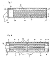
- Fig. 4 shows a third embodiment of the deflection bar in an axial section.
- the jacket 01 carries on a side facing away from the air outlet openings 02 a web 24 on which a (not shown support arm) of the support frame is pivotally fastened, so that the deflection between two stop positions about an axis perpendicular to the cutting plane by about 90th ° is pivotable.
- two cross-flow rotors 06 are arranged, each having a drive via an electric motor 21.
- the electric motors 21 are arranged at opposite ends 22 of the turning bar.
- the shafts 26 of the electric motors 21 are hollow and led out at the end faces of the deflection bar.
- the two electric motors 21 are operable independently of each other, depending on whether one over the entire effective, d. H. provided with air outlet openings 02 width of the shell 01 extending material web to be deflected or a material web, which covers only the left or right half of this effective width.
- the crossover rotor 06 which is not wrapped by a material web, remains unrestrained.
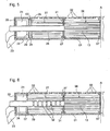
- Fig. 5 shows an axial partial section through a deflection bar according to a fourth embodiment of the invention.
- the structure of the turning bar is symmetrical with respect to the designated by the dotted line A cutting plane with the exception of the support arm 23, of course, only on the in the Fig. 5 shown end 22 of the deflection bar acts while the unillustrated, opposite end 22 is cantilevered.
- the electric motors 21 have a thick, hollow shaft 26, which is led out frontally and allows the supply of the interior 13 of the fixedly coupled to the shaft 26 Querstromrotors 06 with outside air.
- the shaft 26 extends freely through a second fan 27, for. B. cross-flow rotor 27.
- This second cross-flow rotor 27 has at its end facing the motor 21 an end ring 09 with a central opening through which the shaft 26 extends, wherein the free cross section of the opening is considerably larger than the cross section of the shaft 26.
- a chamber 28 which communicates with the environment via a plurality of suction openings 29 broken into the casing 01.
- the supply lines for both electric motors 21 are guided by the support arm 23.
- An end face 31 of the cross-flow rotor 27 lying opposite the end ring 09 can be brought into frictional or frictional connection with the cross-flow rotor 06 by axial displacement of the cross-flow rotor 27 or, alternatively, the cross-flow rotor 06 and the shaft 26.
- the end face 31 and the opposite surface of the cross-flow rotor 06 may be provided with complementary teeth.
- the two cross-flow rotors 06; 27 disengaged, and the electric motor 21 drives only the cross-flow rotor 06 at.
- the adhesion is established, rotate both cross-flow rotors 06; 27.
- the cross-flow rotors 06; 27 are selectively driven in a corresponding manner, the deflection of the Fig. 5 being able to produce a customized width air cushion, each below a quarter-width of material web deflected at one of the two middle quarters of the jacket 01, of a half-width material web deflected at the two central quarters of the jacket 01, less than three quarters wide or one full width To produce material web.
- Fig. 6 shows a fifth embodiment of the deflection bar, which differs from the embodiment of the Fig. 5 characterized in that the chamber 28 is omitted with the suction openings 29; instead, a plurality of apertures 32 are formed in the portion of the shaft 26 extending through the second cross-flow rotor 27.
- a plurality of electric motors 21 may be arranged.
- the electric motors 21 are adjustable to different speeds.
- the speed of the electric motors 21 is adjustable as a function of width and / or speed and / or coefficient of friction and / or tension of the material web.
- the electric motors 21 a deflection bar have z. B. an operating state different speeds.
Landscapes
- Engineering & Computer Science (AREA)
- Mechanical Engineering (AREA)
- Structures Of Non-Positive Displacement Pumps (AREA)
- Preliminary Treatment Of Fibers (AREA)
- Coating Apparatus (AREA)
- Chutes (AREA)
- Load-Engaging Elements For Cranes (AREA)
- Chain Conveyers (AREA)
- Drying Of Solid Materials (AREA)
- Registering, Tensioning, Guiding Webs, And Rollers Therefor (AREA)
- Basic Packing Technique (AREA)
Description
- Die Erfindung betrifft eine Umlenkstange für eine Materialbahn gemäß dem Oberbegriff des Anspruches 1.
- Derartige Umlenkstangen oder Wendestangen werden in großer Zahl z. B. in Zeitungsdruckmaschinen eingesetzt, um Papierbahnen bzw. -stränge umzulenken, zu bündeln und/oder einem Falzapparat zuzuführen. Vielfach haben diese Umlenkstangen einen Mantel mit einer Mehrzahl von Luftaustrittsöffnungen, durch die der Wendestange von außen zugeführte Druckluft austreten kann, um zwischen dem Mantel der Wendestange und der daran umgelenkten Papierbahn ein Luftkissen zu erzeugen, das eine nahezu reibungslose und abschmierlose Umlenkung ermöglicht.
- Diese Umlenkstangen sind meist zu mehreren über Rohrleitungen an eine zentrale Druckluftquelle angeschlossen.
- Der Druckluftbedarf einer Wendestange ist abhängig von ihrer Geometrie, dem Ausmaß der Umschlingung einer an ihr umgelenkten Bahn, deren Breite, Spannung, etc. Der tatsächliche Luftdurchsatz hängt ab von der Leistung der Druckluftquelle sowie von der Geometrie, insbesondere der Länge und dem Strömungswiderstand der von der Druckluftquelle zur Wendestange führenden Rohrleitung.
- Es ist schwierig, einen optimalen Druckluftdurchsatz an mehreren Wendestangen gleichzeitig einzustellen, da jede an einer Wendestange vorgenommene Justierung des Durchsatzes sich an den anderen von der gleichen Druckluftquelle versorgten Wendestangen auswirkt. Unterschiedliche Längen der Rohrleitungen zwischen einer Druckluftquelle und den von ihr versorgten Umlenkstangen machen eine individuelle Justage des Durchsatzes an jeder einzelnen Umlenkstange erforderlich.
- Die
DE 100 63 025 A1 und dieDE 196 47 919 A1 offenbaren Papierleitwalzen mit jeweils einem eigenen Gebläse. - Der Erfindung liegt die Aufgabe zugrunde, eine Umlenkstange für eine Materialbahn mit einfachem Aufbau zu schaffen.
- Die Aufgabe wird erfindungsgemäß durch die Merkmale des Anspruches 1 gelöst.
- Die mit der Erfindung erzielbaren Vorteile bestehen insbesondere darin, dass durch Regeln der elektrischen Versorgung jedes einzelnen Drucklufterzeugers es möglich ist, den Druckluftdurchsatz einer einzelnen Umlenkstange zu regeln, ohne dass damit eine Rückwirkung auf den Druckluftdurchsatz anderer Umlenkstangen verbunden ist.
- Die Umlenkstange ermöglicht durch die Verlagerung des Gebläses ins Innere der Umlenkstange einen besonders kompakten Aufbau, der sich gut für eine modulare Konstruktion oder auch für eine Nachrüstung an bestehenden bahnverarbeitenden Maschinen eignet.
- Eine Gebläsebauform, die sich besonders gut für den Einbau in einer Wendestange eignet, ist ein Querstromrotor.
- Auch ein Elektromotor zum Antreiben des Querstromrotors kann vorteilhaft im Inneren des Mantels der Umlenkstange untergebracht sein.
- Um eine reibungsarme Drehung des Querstromrotors zu ermöglichen und gleichzeitig an den Stirnseiten des Querstromrotors eine große freie Querschnittsfläche für den Luftdurchtritt zur Verfügung zu haben, ist ein Wälzlager zweckmäßigerweise zwischen dem Querstromrotor und der Innenfläche des Mantels angeordnet.
- Eine Ansaugöffnung des Druckerzeugers kann an einer Stirnseite der Umlenkstange angeordnet sein. Dabei kann ein Gehäuse des Querstromrotors an seiner der Ansaugöffnung zugewandten Stirnseite offen sein, um einen möglichst ungehinderten Luftzutritt zu ermöglichen; denkbar ist auch, dass ein Luftkanal von der Ansaugöffnung durch eine hohle Welle des Elektromotors zu dem Querstromrotor geführt ist.
- Alternativ oder ergänzend kann auch wenigstens eine Ansaugöffnung des Druckerzeugers am Mantel angeordnet sein. Dies ist insbesondere zweckmäßig, wenn in dem Mantel mehrere selektiv betreibbare Querstromrotoren untergebracht sind. Der Mantel kann in einzelne Segmente in axialer Richtung und/oder in Umfangsrichtung unterteilt sein.
- Die am Mantel gebildete Ansaugöffnung sollte selbstverständlich möglichst nahe an einem der Enden der Umlenkstange angeordnet sein. Wenn das Ende selbst den Elektromotor enthält, ist die Ansaugöffnung zweckmäßigerweise zwischen diesem Ende und einem den Querstromrotor enthaltenden Abschnitt des Mantels angeordnet.
- Um die Anpassung der Umlenkstange an unterschiedliche Breiten umzulenkender Materialbahnen zu ermöglichen, hat der Drucklufterzeuger eine Mehrzahl von Querstromrotoren, von denen wenigstens einer wahlweise an einen Motor koppelbar und von diesem entkoppelbar ist, um ihn lediglich dann zu betreiben, wenn auf einem von diesem Querstromrotor versorgten Abschnitt der Breite der Umlenkstange tatsächlich eine Materialbahn umgelenkt wird.
- Ausführungsbeispiele der Erfindung sind in den Zeichnungen dargestellt und werden im folgenden näher beschrieben.
- Es zeigen:
- Fig. 1
- einen axialen Schnitt durch eine Wendestange gemäß einer ersten Ausgestaltung der Erfindung;
- Fig. 2
- einen radialen Schnitt durch die Wendestange aus
Fig. 1 ; - Fig. 3
- einen axialen Schnitt durch eine Wendestange gemäß einer zweiten Ausgestaltung der Erfindung;
- Fig. 4
- einen axialen Schnitt durch eine dritte Ausgestaltung, bei der zwei Drucklufterzeuger in der Umlenkstange untergebracht sind;
- Fig. 5
- einen axialen Teilschnitt durch eine Umlenkstange gemäß einer vierten Ausgestaltung, bei der ein Querstromrotor selektiv an den Elektromotor koppelbar bzw. von ihm entkoppelbar ist.
- Die erste Ausgestaltung wird zunächst mit Bezug auf die
Fig. 1 und 2 beschrieben. Die Wendestange hat einen hohlzylindrischen Mantel 01, der auf einer Hälfte seines Umfangs mit regelmäßig verteilten Luftaustrittsöffnungen 02 versehen ist. Der Mantel 01 ist an einer Stirnseite 03 offen; an seinem gegenüberliegenden Ende ist er über ein unter einem Winkel von ca. 45° angefügtes Rohr 04 mit einem (in derFig. 1 nicht gezeigten) Traggestell verbunden. - Ein Gebläse 06, z. B. ein Querstromrotor 06 erstreckt sich im wesentlichen über die gesamte Länge des Mantels 01 in dessen hohlem Inneren und ist mit Hilfe zweier Lager 07, z. B. Wälzlager 07 drehbar gelagert, die jeweils mit einem äußeren Ring an der Innenseite des Mantels 01 anliegen und mit einem inneren Ring jeweils eine Stirnplatte 08 bzw. einen Stirnring 09 des Querstromrotors 06 tragen.
- Zwischen der Stirnplatte 08 und dem Stirnring 09 erstrecken sich, in Umfangsrichtung gleichmäßig verteilt, eine Mehrzahl von Lamellen 11 mit gekrümmtem Querschnitt in axialer Richtung des Mantels 01. Die Lamellen 11 erzeugen bei einer Drehung des Querstromrotors 06 einen Überdruck in einem Zwischenraum 12 zwischen dem Querstromrotor 06 und dem Mantel 01, so dass Luft aus dem Zwischenraum 12 über die Luftaustrittsöffnungen 02 ausströmt, um ein Luftkissen für eine um den Mantel 01 herumgeschlungene (nicht dargestellte) Materialbahn, z. B. eine Papierbahn zu schaffen. In den durch die Drehung unter Unterdruck gesetzten Innenraum des Querstromrotors 06 fließt Außenluft über die offene Stirnseite 03 des Mantels 01 und die Öffnung des Stirnrings 09 des Querstromrotors 06 nach.
- Die Drehung des Querstromrotors 06 ist angetrieben durch eine an der Stirnplatte 08 angreifende Welle 14, die über ein Kardangelenk 16 an eine durch das Rohr 04 geführte Welle 17 gekoppelt ist. Ein (nicht dargestellter) Elektromotor zum Antreiben der Welle 17 ist an dem Traggestell montiert.
- Die Verbindung des Rohrs 04 mit dem Traggestell kann mit einem großen freien Durchgangsquerschnitt ausgebildet sein, und auch die Stirnplatte 08 kann (nicht dargestellte) Durchbrechungen aufweisen, um ein Nachströmen von Luft in den Innenraum 13 des Motors auch von Seiten des Rohrs 04 her zu ermöglichen.
- Bei der in
Fig. 3 gezeigten zweiten Ausgestaltung werden, wie auch bei den nachfolgenden Ausgestaltungen, gleiche Bezugszeichen für gleiche Elemente wie inFig. 1 und 2 verwendet. - Bei der Ausgestaltung der
Fig. 3 ist ein Elektromotor 21 zum Drehantreiben des Querstromrotors 06 innerhalb des Mantels 01 an einem geschlossenen Ende 22 angeordnet. Ein Tragarm 23, der die Wendestange mit dem (nicht dargestellten) Traggestell verbindet, greift außen an dem geschlossenen Ende 22 an. Durch den Tragarm 23 ist eine elektrische Leitung zur Stromversorgung des Elektromotors 21 geführt. Die dem Ende 22 gegenüberliegende Stirnseite 03 ist wie beim ersten Ausführungsbeispiel offen, so dass Außenluft durch diese Öffnung in den Innenraum 13 gesaugt wird. - Der Querstromrotor 06 ist über die Stirnplatte 08 unmittelbar mit der Antriebswelle des Elektromotors 21 verbunden; der Stirnring 09 ist wiederum durch ein zwischen ihm und dem Mantel 01 angeordnetes Wälzlager 07 gehalten.
-
Fig. 4 zeigt eine dritte Ausgestaltung der Umlenkstange in einem axialen Schnitt. Bei dieser Ausgestaltung trägt der Mantel 01 an einer von den Luftaustrittsöffnungen 02 abgewandten Seite einen Steg 24, an dem ein (nicht dargestellter Tragarm) des Traggestells schwenkbar befestigbar ist, so dass die Umlenkstange zwischen zwei Anschlagpositionen um eine zur Schnittebene senkrechte Achse um ca. 90° schwenkbar ist. - Im Inneren des Mantels 01 sind zwei Querstromrotoren 06 angeordnet, die jeweils als Antrieb über einen Elektromotor 21 verfügen. Die Elektromotoren 21 sind an einander gegenüberliegenden Enden 22 der Wendestange angeordnet. Um einen Zutritt von Außenluft in die Innenräume 13 der Querstromrotoren 06 zu ermöglichen, sind die Wellen 26 der Elektromotoren 21 hohl und an den Stirnflächen der Umlenkstange herausgeführt.
- Die zwei Elektromotoren 21 sind unabhängig voneinander betreibbar, je nachdem, ob eine sich über die gesamte wirksame, d. h. mit Luftaustrittsöffnungen 02 versehene Breite des Mantels 01 erstreckende Materialbahn umgelenkt werden soll oder eine Materialbahn, die jeweils nur die linke oder rechte Hälfte dieser wirksamen Breite bedeckt.
- Der nicht von einer Materialbahn umschlungene Querstromrotor 06 bleibt unangetrieben.
- Da die Zwischenräume 12, die den linken und rechten Querstromrotor 06 umgeben, voneinander jeweils durch die Wälzlager 07 oder anderer Abdeckungen getrennt sind, kommt es allenfalls zu einem geringen Entweichen von Druckluft aus dem den angetriebenen Querstromrotor 06 umgebenden Zwischenraum 12 in axialer Richtung; der bei weitem überwiegende Teil der erzeugten Druckluft entweicht durch die Luftaustrittsöffnungen 02 und erzeugt so das gewünschte Luftkissen zwischen dem Mantel 01 und der umzulenkenden Materialbahn.
-
Fig. 5 zeigt einen axialen Teilschnitt durch eine Umlenkstange gemäß einer vierten Ausgestaltung der Erfindung. Der Aufbau der Wendestange ist in Bezug auf die durch die strichpunktierte Linie A bezeichnete Schnittebene symmetrisch mit Ausnahme des Tragarms 23, der selbstverständlich nur an dem in derFig. 5 gezeigten Ende 22 der Umlenkstange angreift, während das nicht dargestellte, gegenüber liegende Ende 22 fliegend gelagert ist. - Wie bei der Ausgestaltung der
Fig. 4 haben die Elektromotoren 21 eine dicke, hohle Welle 26, die stirnseitig herausgeführt ist und die Versorgung des Innenraums 13 des fest an die Welle 26 gekoppelten Querstromrotors 06 mit Außenluft ermöglicht. Die Welle 26 erstreckt sich frei durch einen zweites Gebläse 27, z. B. Querstromrotor 27. Dieser zweite Querstromrotor 27 weist an seiner dem Motor 21 zugewandten Stirnseite einen Stirnring 09 mit einer zentralen Öffnung auf, durch die die Welle 26 verläuft, wobei der freie Querschnitt der Öffnung erheblich größer als der Querschnitt der Welle 26 ist. Zwischen dem Elektromotor 21 und dem Stirnring 09 befindet sich eine Kammer 28, die über eine Mehrzahl von in den Mantel 01 gebrochenen Ansaugöffnungen 29 mit der Umgebung in Verbindung steht. - Die Versorgungsleitungen für beide Elektromotoren 21 sind durch den Tragarm 23 geführt.
- Eine dem Stirnring 09 gegenüber liegende Stirnfläche 31 des Querstromrotors 27 ist durch axiales Verschieben des Querstromrotors 27 oder, alternativ, des Querstromrotors 06 und der Welle 26, mit dem Querstromrotor 06 in Reib- oder Kraftschluss bringbar. Zur Verstärkung des Kraftschlusses können die Stirnfläche 31 und die gegenüberliegende Fläche des Querstromrotors 06 mit komplementären Verzahnungen versehen sein.
- In der in
Fig. 5 gezeigten Konfiguration sind die zwei Querstromrotoren 06; 27 außer Eingriff, und der Elektromotor 21 treibt nur den Querstromrotor 06 an. Wenn der Kraftschluss hergestellt ist, rotieren beide Querstromrotoren 06; 27. Da auch in der nicht dargestellten gegenüberliegenden Hälfte des Mantels 01 die Querstromrotoren 06; 27 in entsprechender Weise selektiv antreibbar sind, ist die Umlenkstange derFig. 5 in der Lage, ein Luftkissen von angepasster Breite jeweils unter einer viertelbreiten Materialbahn, die an einem der zwei mittleren Viertel des Mantels 01 umgelenkt wird, einer halbbreiten Materialbahn, die an den zwei mittleren Vierteln des Mantels 01 umgelenkt wird, unter einer dreiviertelbreiten oder einer vollbreiten Materialbahn zu erzeugen. -
Fig. 6 zeigt eine fünfte Ausgestaltung der Umlenkstange, die sich von der Ausgestaltung derFig. 5 dadurch unterscheidet, dass die Kammer 28 mit den Ansaugöffnungen 29 entfallen ist; statt dessen ist eine Mehrzahl von Öffnungen 32 in dem sich durch den zweiten Querstromrotor 27 erstreckenden Abschnitt der Welle 26 gebildet. - Wenn bei dieser Ausgestaltung nur der Querstromrotor 06 von dem Elektromotor 21 angetrieben wird und der zweite Querstromrotor 27 steht, so wird zum Ausgleich des Unterdrucks im Innenraum 13 des Querstromrotors 06 Luft einerseits durch die Welle 26 vom Ende 22, andererseits durch die Öffnungen 32 aus dem Innenraum 13 des zweiten Querstromrotors 27 angesaugt. Dies ist möglich, da über die Luftaustrittsöffnungen 02 des vom Querstromrotor 27 ausgefüllten Abschnitts des Mantels 01 Luft ins Innere nachfließen kann. D. h. die Luftaustrittsöffnungen 02 dieses Abschnitts übernehmen die Aufgabe der Ansaugöffnungen 29 der vierten Ausgestattung, wenn der Querstromrotor 27 nicht rotiert. Wenn hingegen beide Querstromrotoren 06; 27 gekoppelt rotieren, so werden beide über die Welle 26 von dem Enden 22 her mit Außenluft versorgt, von der ein Teil aus der Welle 26 durch die Öffnungen 32 in den Querstromrotor 27 nachströmt.
- In der Umlenkstange können mehrere Elektromotoren 21 angeordnet sein.
- Die Elektromotoren 21 sind auf unterschiedliche Drehzahlen einstellbar.
- Die Drehzahl der Elektromotoren 21 ist in Abhängigkeit von Breite und/oder Geschwindigkeit und/oder Reibwert und/oder Spannung der Materialbahn einstellbar.
- Die Elektromotoren 21 einer Umlenkstange weisen z. B. einem Betriebszustand unterschiedliche Drehzahlen auf.
-
- 01
- Mantel
- 02
- Luftaustrittsöffnung
- 03
- Stirnseite
- 04
- Rohr
- 05
- -
- 06
- Gebläse, Querstromrotor
- 07
- Lager, Wälzlager
- 08
- Stirnplatte
- 09
- Stirnring
- 10
- -
- 11
- Lamelle
- 12
- Zwischenraum (06; 01)
- 13
- Innenraum (06)
- 14
- Welle
- 15
- -
- 16
- Kardangelenk
- 17
- Welle (04)
- 18
- -
- 19
- -
- 20
- -
- 21
- Elektromotor
- 22
- Ende
- 23
- Tragarm
- 24
- Steg
- 25
- -
- 26
- Welle (21)
- 27
- Gebläse, Querstromrotor
- 28
- Kammer
- 29
- Ansaugöffnung
- 30
- -
- 31
- Stirnfläche (27)
- 32
- Öffnung
Claims (13)
- Umlenkstange zum Umlenken einer Materialbahn, mit einem mit einer Mehrzahl von Luftaustrittsöffnungen (02) versehenen Mantel (01), wobei ein Gebläse (06; 27) zum Versorgen der Luftaustrittsöffnungen (02) im Inneren des Mantels (01) untergebracht ist, dadurch gekennzeichnet, dass das Gebläse (06; 27) wenigstens einen Querstromrotor (06; 27) umfasst.
- Umlenkstange nach Anspruch 1, dadurch gekennzeichnet, dass ein Elektromotor (21) zum Antreiben des Querstromrotors (06; 27) im Inneren des Mantels (01) untergebracht ist.
- Umlenkstange nach Anspruch 1 oder 2, dadurch gekennzeichnet, dass ein Wälzlager (07) zwischen dem Querstromrotor (06; 27) und der Innenfläche des Mantels (01) angeordnet ist.
- Umlenkstange nach einem der Ansprüche 1 bis 3, dadurch gekennzeichnet, dass eine Ansaugöffnung des Gebläses (06; 27) an einem Ende (22) der Umlenkstange angeordnet ist.
- Umlenkstange nach Anspruch 4, dadurch gekennzeichnet, dass ein Luftkanal von der Ansaugöffnung (29) zu dem Querstromrotor (06; 27) durch eine hohle Welle (26) des Elektromotors (21) geführt ist.
- Umlenkstange nach einem der Ansprüche 1 bis 5, dadurch gekennzeichnet, dass eine Ansaugöffnung (29) des Druckerzeugers am Mantel (01) angeordnet ist.
- Umlenkstange nach Anspruch 2 und 6, dadurch gekennzeichnet, dass der Elektromotor (21) an einem Ende (22) des Mantels (01) untergebracht ist und dass die Ansaugöffnung (29) zwischen dem Ende (22) und einem den Querstromrotor (06; 27) enthaltenden Abschnitt des Mantels (01) angeordnet ist.
- Umlenkstange nach einem der Ansprüche 1 bis 7, dadurch gekennzeichnet, dass der Drucklufterzeuger eine Mehrzahl von Querstromrotoren (06; 27) umfasst, von denen wenigstens einer wahlweise an einen Elektromotor (21) koppelbar und entkoppelbar ist.
- Umlenkstange nach Anspruch 8, dadurch gekennzeichnet, dass der entkoppelbare Querstromrotor (27) zwischen dem Elektromotor (21) und einem fest an dem Elektromotor (21) gekoppelten Querstromrotor (06) angeordnet ist.
- Umlenkstange nach Anspruch 9, soweit auf Anspruch 5 rückbezogen, dadurch gekennzeichnet, dass die hohle Welle (26) in Höhe des entkoppelbaren Querstromrotors (27) wenigstens eine Öffnung (32) aufweist.
- Umlenkstange nach Anspruch 2, dadurch gekennzeichnet, dass mehrere Elektromotoren (21) in einer Umlenkstange angeordnet sind.
- Umlenkstange nach Anspruch 11, dadurch gekennzeichnet, dass die Elektromotoren (21) auf unterschiedliche Drehzahlen einstellbar sind.
- Umlenkstange nach Anspruch 11 oder 12, dadurch gekennzeichnet, dass die Drehzahl der Elektromotoren (21) in Abhängigkeit von Breite und/oder Geschwindigkeit und/oder Reibwert und/oder Spannung der Materialbahn einstellbar sind.
Applications Claiming Priority (3)
| Application Number | Priority Date | Filing Date | Title |
|---|---|---|---|
| DE10232555 | 2002-07-18 | ||
| DE10232555A DE10232555B3 (de) | 2002-07-18 | 2002-07-18 | Umlenkstange für eine Materialbahn |
| PCT/DE2003/001131 WO2004016534A1 (de) | 2002-07-18 | 2003-04-07 | Umlenkstange für eine materialbahn |
Publications (2)
| Publication Number | Publication Date |
|---|---|
| EP1523447A1 EP1523447A1 (de) | 2005-04-20 |
| EP1523447B1 true EP1523447B1 (de) | 2008-12-31 |
Family
ID=29723909
Family Applications (1)
| Application Number | Title | Priority Date | Filing Date |
|---|---|---|---|
| EP03727182A Expired - Lifetime EP1523447B1 (de) | 2002-07-18 | 2003-04-07 | Umlenkstange für eine materialbahn |
Country Status (5)
| Country | Link |
|---|---|
| EP (1) | EP1523447B1 (de) |
| AT (1) | ATE419208T1 (de) |
| AU (1) | AU2003233933A1 (de) |
| DE (2) | DE10232555B3 (de) |
| WO (1) | WO2004016534A1 (de) |
Families Citing this family (2)
| Publication number | Priority date | Publication date | Assignee | Title |
|---|---|---|---|---|
| DE102005000094A1 (de) * | 2005-07-26 | 2007-02-01 | Voith Patent Gmbh | Wickelkern, Wickelmaschine und Verfahren zum Aufwickeln einer Materialbahn |
| DE102010006208A1 (de) * | 2010-01-29 | 2011-08-04 | Eastman Kodak Company, N.Y. | Verfahren und Vorrichtung zum Wenden von bahnförmigen Substraten |
Family Cites Families (4)
| Publication number | Priority date | Publication date | Assignee | Title |
|---|---|---|---|---|
| SE196703C1 (de) * | 1956-04-07 | 1965-06-15 | Svenska Flaektfabriken Ab | |
| JPS597655A (ja) * | 1982-07-05 | 1984-01-14 | Nisshin Steel Co Ltd | 低接触圧サポ−トロ−ル装置 |
| DE19647919A1 (de) * | 1996-11-20 | 1998-05-28 | Voith Sulzer Papiermasch Gmbh | Vorrichtung zur Führung einer Materialbahn |
| DE10063025B4 (de) * | 2000-12-16 | 2005-05-12 | Man Roland Druckmaschinen Ag | Feststehende Papierleiteinrichtung |
-
2002
- 2002-07-18 DE DE10232555A patent/DE10232555B3/de not_active Expired - Fee Related
-
2003
- 2003-04-07 AU AU2003233933A patent/AU2003233933A1/en not_active Abandoned
- 2003-04-07 WO PCT/DE2003/001131 patent/WO2004016534A1/de not_active Ceased
- 2003-04-07 EP EP03727182A patent/EP1523447B1/de not_active Expired - Lifetime
- 2003-04-07 DE DE50311009T patent/DE50311009D1/de not_active Expired - Fee Related
- 2003-04-07 AT AT03727182T patent/ATE419208T1/de not_active IP Right Cessation
Also Published As
| Publication number | Publication date |
|---|---|
| EP1523447A1 (de) | 2005-04-20 |
| WO2004016534A1 (de) | 2004-02-26 |
| DE50311009D1 (de) | 2009-02-12 |
| DE10232555B3 (de) | 2004-01-15 |
| ATE419208T1 (de) | 2009-01-15 |
| AU2003233933A1 (en) | 2004-03-03 |
Similar Documents
| Publication | Publication Date | Title |
|---|---|---|
| DE4238564C2 (de) | Elektrowerkzeug | |
| EP1586769B1 (de) | Turmkopf einer Windenergieanlage | |
| DE102007061597B4 (de) | Elektrische Maschine mit Doppelaxiallüfter | |
| CH621477A5 (de) | ||
| AT412327B (de) | Strangführungsrolle | |
| WO2005016578A1 (de) | Innengekühlte strangführungsrolle | |
| DE102006004421A1 (de) | Bandförderer und Trommelmotor eines Bandförderers | |
| DE3028632C2 (de) | Regenerator mit einer in einem Gehäuse untergebrachten, um eine Drehachse umlaufenden, hohlzylindrischen Wärmetauscherwalze | |
| EP3789617A1 (de) | Ventilator | |
| DE102015121695A1 (de) | Drehvorrichtung | |
| DE69119096T2 (de) | Kupplungsvorrichtung mit elektromagnetischem Pulver als Wirkstoff | |
| EP1697054A1 (de) | Aussenläuferantrieb | |
| EP3120085B1 (de) | Lüftungsvorrichtung | |
| EP1523447B1 (de) | Umlenkstange für eine materialbahn | |
| DE102007027840A1 (de) | Rotierender Wärmetauscher und Lüftungssystem hiermit | |
| DE102023105784A1 (de) | Pumpenventilanordnung | |
| EP0650458A1 (de) | Bogenführungszylinder einer druckmaschine. | |
| AT394434B (de) | Geblaeseanordnung | |
| DE29908433U1 (de) | Walze | |
| EP1167771A2 (de) | Axialventilator mit reversierbarer Strömungsrichtung | |
| DE202012101190U1 (de) | Saugbagger zur pneumatischen Aufnahme von Sauggut | |
| DE60010892T2 (de) | Segmentierte saugwalze | |
| EP0663360B1 (de) | Bogenführungszylinder | |
| DE10058857A1 (de) | Gasgekühlte Maschine, insbesondere Turbogenerator | |
| DE3230731C2 (de) | Rollenvorrichtung mit eingebautem Motor |
Legal Events
| Date | Code | Title | Description |
|---|---|---|---|
| PUAI | Public reference made under article 153(3) epc to a published international application that has entered the european phase |
Free format text: ORIGINAL CODE: 0009012 |
|
| 17P | Request for examination filed |
Effective date: 20040220 |
|
| AK | Designated contracting states |
Kind code of ref document: A1 Designated state(s): AT BE BG CH CY CZ DE DK EE ES FI FR GB GR HU IE IT LI LU MC NL PT SE SI SK TR |
|
| AX | Request for extension of the european patent |
Extension state: AL LT LV MK |
|
| DAX | Request for extension of the european patent (deleted) | ||
| GRAP | Despatch of communication of intention to grant a patent |
Free format text: ORIGINAL CODE: EPIDOSNIGR1 |
|
| GRAS | Grant fee paid |
Free format text: ORIGINAL CODE: EPIDOSNIGR3 |
|
| GRAA | (expected) grant |
Free format text: ORIGINAL CODE: 0009210 |
|
| AK | Designated contracting states |
Kind code of ref document: B1 Designated state(s): AT BE BG CH CY CZ DE DK EE ES FI FR GB GR HU IE IT LI LU MC NL PT SE SI SK TR |
|
| REG | Reference to a national code |
Ref country code: GB Ref legal event code: FG4D Free format text: NOT ENGLISH Ref country code: CH Ref legal event code: EP |
|
| REF | Corresponds to: |
Ref document number: 50311009 Country of ref document: DE Date of ref document: 20090212 Kind code of ref document: P |
|
| REG | Reference to a national code |
Ref country code: IE Ref legal event code: FG4D Free format text: LANGUAGE OF EP DOCUMENT: GERMAN |
|
| PG25 | Lapsed in a contracting state [announced via postgrant information from national office to epo] |
Ref country code: NL Free format text: LAPSE BECAUSE OF FAILURE TO SUBMIT A TRANSLATION OF THE DESCRIPTION OR TO PAY THE FEE WITHIN THE PRESCRIBED TIME-LIMIT Effective date: 20081231 Ref country code: SI Free format text: LAPSE BECAUSE OF FAILURE TO SUBMIT A TRANSLATION OF THE DESCRIPTION OR TO PAY THE FEE WITHIN THE PRESCRIBED TIME-LIMIT Effective date: 20081231 Ref country code: FI Free format text: LAPSE BECAUSE OF FAILURE TO SUBMIT A TRANSLATION OF THE DESCRIPTION OR TO PAY THE FEE WITHIN THE PRESCRIBED TIME-LIMIT Effective date: 20081231 |
|
| NLV1 | Nl: lapsed or annulled due to failure to fulfill the requirements of art. 29p and 29m of the patents act | ||
| PG25 | Lapsed in a contracting state [announced via postgrant information from national office to epo] |
Ref country code: ES Free format text: LAPSE BECAUSE OF FAILURE TO SUBMIT A TRANSLATION OF THE DESCRIPTION OR TO PAY THE FEE WITHIN THE PRESCRIBED TIME-LIMIT Effective date: 20090411 Ref country code: EE Free format text: LAPSE BECAUSE OF FAILURE TO SUBMIT A TRANSLATION OF THE DESCRIPTION OR TO PAY THE FEE WITHIN THE PRESCRIBED TIME-LIMIT Effective date: 20081231 |
|
| REG | Reference to a national code |
Ref country code: IE Ref legal event code: FD4D |
|
| PG25 | Lapsed in a contracting state [announced via postgrant information from national office to epo] |
Ref country code: PT Free format text: LAPSE BECAUSE OF FAILURE TO SUBMIT A TRANSLATION OF THE DESCRIPTION OR TO PAY THE FEE WITHIN THE PRESCRIBED TIME-LIMIT Effective date: 20090601 Ref country code: SE Free format text: LAPSE BECAUSE OF FAILURE TO SUBMIT A TRANSLATION OF THE DESCRIPTION OR TO PAY THE FEE WITHIN THE PRESCRIBED TIME-LIMIT Effective date: 20090331 Ref country code: CZ Free format text: LAPSE BECAUSE OF FAILURE TO SUBMIT A TRANSLATION OF THE DESCRIPTION OR TO PAY THE FEE WITHIN THE PRESCRIBED TIME-LIMIT Effective date: 20081231 |
|
| PGFP | Annual fee paid to national office [announced via postgrant information from national office to epo] |
Ref country code: FR Payment date: 20090421 Year of fee payment: 7 |
|
| PG25 | Lapsed in a contracting state [announced via postgrant information from national office to epo] |
Ref country code: SK Free format text: LAPSE BECAUSE OF FAILURE TO SUBMIT A TRANSLATION OF THE DESCRIPTION OR TO PAY THE FEE WITHIN THE PRESCRIBED TIME-LIMIT Effective date: 20081231 |
|
| PG25 | Lapsed in a contracting state [announced via postgrant information from national office to epo] |
Ref country code: IE Free format text: LAPSE BECAUSE OF FAILURE TO SUBMIT A TRANSLATION OF THE DESCRIPTION OR TO PAY THE FEE WITHIN THE PRESCRIBED TIME-LIMIT Effective date: 20081231 Ref country code: DK Free format text: LAPSE BECAUSE OF FAILURE TO SUBMIT A TRANSLATION OF THE DESCRIPTION OR TO PAY THE FEE WITHIN THE PRESCRIBED TIME-LIMIT Effective date: 20081231 |
|
| PGFP | Annual fee paid to national office [announced via postgrant information from national office to epo] |
Ref country code: CH Payment date: 20090423 Year of fee payment: 7 |
|
| BERE | Be: lapsed |
Owner name: KOENIG & BAUER A.G. Effective date: 20090430 |
|
| PLBE | No opposition filed within time limit |
Free format text: ORIGINAL CODE: 0009261 |
|
| STAA | Information on the status of an ep patent application or granted ep patent |
Free format text: STATUS: NO OPPOSITION FILED WITHIN TIME LIMIT |
|
| PGFP | Annual fee paid to national office [announced via postgrant information from national office to epo] |
Ref country code: GB Payment date: 20090424 Year of fee payment: 7 |
|
| 26N | No opposition filed |
Effective date: 20091001 |
|
| PG25 | Lapsed in a contracting state [announced via postgrant information from national office to epo] |
Ref country code: DE Free format text: LAPSE BECAUSE OF NON-PAYMENT OF DUE FEES Effective date: 20091103 Ref country code: BG Free format text: LAPSE BECAUSE OF FAILURE TO SUBMIT A TRANSLATION OF THE DESCRIPTION OR TO PAY THE FEE WITHIN THE PRESCRIBED TIME-LIMIT Effective date: 20090331 |
|
| PG25 | Lapsed in a contracting state [announced via postgrant information from national office to epo] |
Ref country code: MC Free format text: LAPSE BECAUSE OF NON-PAYMENT OF DUE FEES Effective date: 20090430 |
|
| PG25 | Lapsed in a contracting state [announced via postgrant information from national office to epo] |
Ref country code: BE Free format text: LAPSE BECAUSE OF NON-PAYMENT OF DUE FEES Effective date: 20090430 |
|
| PG25 | Lapsed in a contracting state [announced via postgrant information from national office to epo] |
Ref country code: AT Free format text: LAPSE BECAUSE OF NON-PAYMENT OF DUE FEES Effective date: 20090407 |
|
| PGFP | Annual fee paid to national office [announced via postgrant information from national office to epo] |
Ref country code: IT Payment date: 20100419 Year of fee payment: 8 |
|
| PG25 | Lapsed in a contracting state [announced via postgrant information from national office to epo] |
Ref country code: GR Free format text: LAPSE BECAUSE OF FAILURE TO SUBMIT A TRANSLATION OF THE DESCRIPTION OR TO PAY THE FEE WITHIN THE PRESCRIBED TIME-LIMIT Effective date: 20090401 |
|
| REG | Reference to a national code |
Ref country code: CH Ref legal event code: PL |
|
| GBPC | Gb: european patent ceased through non-payment of renewal fee |
Effective date: 20100407 |
|
| REG | Reference to a national code |
Ref country code: FR Ref legal event code: ST Effective date: 20101230 |
|
| PG25 | Lapsed in a contracting state [announced via postgrant information from national office to epo] |
Ref country code: LI Free format text: LAPSE BECAUSE OF NON-PAYMENT OF DUE FEES Effective date: 20100430 Ref country code: CH Free format text: LAPSE BECAUSE OF NON-PAYMENT OF DUE FEES Effective date: 20100430 |
|
| PG25 | Lapsed in a contracting state [announced via postgrant information from national office to epo] |
Ref country code: GB Free format text: LAPSE BECAUSE OF NON-PAYMENT OF DUE FEES Effective date: 20100407 |
|
| PG25 | Lapsed in a contracting state [announced via postgrant information from national office to epo] |
Ref country code: LU Free format text: LAPSE BECAUSE OF NON-PAYMENT OF DUE FEES Effective date: 20090407 |
|
| PG25 | Lapsed in a contracting state [announced via postgrant information from national office to epo] |
Ref country code: HU Free format text: LAPSE BECAUSE OF FAILURE TO SUBMIT A TRANSLATION OF THE DESCRIPTION OR TO PAY THE FEE WITHIN THE PRESCRIBED TIME-LIMIT Effective date: 20090701 |
|
| PG25 | Lapsed in a contracting state [announced via postgrant information from national office to epo] |
Ref country code: TR Free format text: LAPSE BECAUSE OF FAILURE TO SUBMIT A TRANSLATION OF THE DESCRIPTION OR TO PAY THE FEE WITHIN THE PRESCRIBED TIME-LIMIT Effective date: 20081231 |
|
| PG25 | Lapsed in a contracting state [announced via postgrant information from national office to epo] |
Ref country code: CY Free format text: LAPSE BECAUSE OF FAILURE TO SUBMIT A TRANSLATION OF THE DESCRIPTION OR TO PAY THE FEE WITHIN THE PRESCRIBED TIME-LIMIT Effective date: 20081231 |
|
| PG25 | Lapsed in a contracting state [announced via postgrant information from national office to epo] |
Ref country code: IT Free format text: LAPSE BECAUSE OF NON-PAYMENT OF DUE FEES Effective date: 20110407 |
|
| PG25 | Lapsed in a contracting state [announced via postgrant information from national office to epo] |
Ref country code: FR Free format text: LAPSE BECAUSE OF NON-PAYMENT OF DUE FEES Effective date: 20100430 |