EP1523177A2 - Projektor mit Aufzeichnungsvorrichtung - Google Patents
Projektor mit Aufzeichnungsvorrichtung Download PDFInfo
- Publication number
- EP1523177A2 EP1523177A2 EP20040023932 EP04023932A EP1523177A2 EP 1523177 A2 EP1523177 A2 EP 1523177A2 EP 20040023932 EP20040023932 EP 20040023932 EP 04023932 A EP04023932 A EP 04023932A EP 1523177 A2 EP1523177 A2 EP 1523177A2
- Authority
- EP
- European Patent Office
- Prior art keywords
- section
- image
- imaging
- projection
- screen
- Prior art date
- Legal status (The legal status is an assumption and is not a legal conclusion. Google has not performed a legal analysis and makes no representation as to the accuracy of the status listed.)
- Granted
Links
- 238000003384 imaging method Methods 0.000 claims abstract description 117
- 230000003287 optical effect Effects 0.000 claims description 92
- 238000001514 detection method Methods 0.000 claims description 3
- 238000000034 method Methods 0.000 claims description 3
- 230000008859 change Effects 0.000 abstract description 15
- 230000006870 function Effects 0.000 description 17
- 238000010586 diagram Methods 0.000 description 10
- 230000005540 biological transmission Effects 0.000 description 5
- 230000007246 mechanism Effects 0.000 description 4
- 230000001360 synchronised effect Effects 0.000 description 4
- 238000004891 communication Methods 0.000 description 3
- 239000004973 liquid crystal related substance Substances 0.000 description 3
- 230000006835 compression Effects 0.000 description 2
- 238000007906 compression Methods 0.000 description 2
- 230000006837 decompression Effects 0.000 description 2
- 230000002093 peripheral effect Effects 0.000 description 2
- 238000006243 chemical reaction Methods 0.000 description 1
- 230000000994 depressogenic effect Effects 0.000 description 1
- 229910052743 krypton Inorganic materials 0.000 description 1
- DNNSSWSSYDEUBZ-UHFFFAOYSA-N krypton atom Chemical compound [Kr] DNNSSWSSYDEUBZ-UHFFFAOYSA-N 0.000 description 1
- 238000012986 modification Methods 0.000 description 1
- 230000004048 modification Effects 0.000 description 1
- 239000007787 solid Substances 0.000 description 1
Images



Classifications
-
- G—PHYSICS
- G03—PHOTOGRAPHY; CINEMATOGRAPHY; ANALOGOUS TECHNIQUES USING WAVES OTHER THAN OPTICAL WAVES; ELECTROGRAPHY; HOLOGRAPHY
- G03B—APPARATUS OR ARRANGEMENTS FOR TAKING PHOTOGRAPHS OR FOR PROJECTING OR VIEWING THEM; APPARATUS OR ARRANGEMENTS EMPLOYING ANALOGOUS TECHNIQUES USING WAVES OTHER THAN OPTICAL WAVES; ACCESSORIES THEREFOR
- G03B17/00—Details of cameras or camera bodies; Accessories therefor
- G03B17/48—Details of cameras or camera bodies; Accessories therefor adapted for combination with other photographic or optical apparatus
- G03B17/54—Details of cameras or camera bodies; Accessories therefor adapted for combination with other photographic or optical apparatus with projector
-
- G—PHYSICS
- G03—PHOTOGRAPHY; CINEMATOGRAPHY; ANALOGOUS TECHNIQUES USING WAVES OTHER THAN OPTICAL WAVES; ELECTROGRAPHY; HOLOGRAPHY
- G03B—APPARATUS OR ARRANGEMENTS FOR TAKING PHOTOGRAPHS OR FOR PROJECTING OR VIEWING THEM; APPARATUS OR ARRANGEMENTS EMPLOYING ANALOGOUS TECHNIQUES USING WAVES OTHER THAN OPTICAL WAVES; ACCESSORIES THEREFOR
- G03B21/00—Projectors or projection-type viewers; Accessories therefor
-
- G—PHYSICS
- G03—PHOTOGRAPHY; CINEMATOGRAPHY; ANALOGOUS TECHNIQUES USING WAVES OTHER THAN OPTICAL WAVES; ELECTROGRAPHY; HOLOGRAPHY
- G03B—APPARATUS OR ARRANGEMENTS FOR TAKING PHOTOGRAPHS OR FOR PROJECTING OR VIEWING THEM; APPARATUS OR ARRANGEMENTS EMPLOYING ANALOGOUS TECHNIQUES USING WAVES OTHER THAN OPTICAL WAVES; ACCESSORIES THEREFOR
- G03B21/00—Projectors or projection-type viewers; Accessories therefor
- G03B21/14—Details
- G03B21/53—Means for automatic focusing, e.g. to compensate thermal effects
-
- H—ELECTRICITY
- H04—ELECTRIC COMMUNICATION TECHNIQUE
- H04N—PICTORIAL COMMUNICATION, e.g. TELEVISION
- H04N5/00—Details of television systems
- H04N5/74—Projection arrangements for image reproduction, e.g. using eidophor
-
- H—ELECTRICITY
- H04—ELECTRIC COMMUNICATION TECHNIQUE
- H04N—PICTORIAL COMMUNICATION, e.g. TELEVISION
- H04N9/00—Details of colour television systems
- H04N9/12—Picture reproducers
- H04N9/31—Projection devices for colour picture display, e.g. using electronic spatial light modulators [ESLM]
- H04N9/3141—Constructional details thereof
- H04N9/317—Convergence or focusing systems
Definitions
- the imaging apparatus further includes a position adjustable imaging optical section that image-forms an optical image imaged by the imaging section.
- the imaging apparatus further includes an imaging-side driving section that drives the imaging optical section.
- the imaging apparatus further includes a receiving section that receives the angle-of-view information transmitted from the image projecting apparatus.
- the imaging apparatus further includes a control section that causes the imaging-side driving section to drive the imaging optical section based on the angle-of-view information received by the receiving section, thereby controlling a zoom ratio of the imaging optical section to a zoom ratio corresponding to a zoom ratio of the projection optical section.
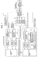
- the image processing and controlling section 3 generates an image file recorded on the image recording section 4 and a display signal based on document data for presentation.
- the image processing and controlling section 3 also generates a display signal based on an external input signal input from an external equipment connected to the projector 1, and sends it to the projecting section 6.
- the external input signal refers to an image signal of a projection document (character, diagram, etc.), and a video signal thereof that are sent from, for example, a personal computer, and an input signal of a character and a line drawing sent from a tablet.
- the image processing and controlling section 3 when a shooting operation is executed by the user, the image processing and controlling section 3 generates an image file based on image data sent from the camera section 7 and records it on the image recording section 4.
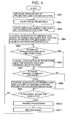
- FIG. 2 is a flowchart illustrating an operation of the projector 1 after power is turned on.
- the control section 2 drives the projector lens 62 and the imaging lens 71 to initialize each zoom ratio to a predetermined zoom ratio such as 1:1 (step SA1), and then starts to project the document, the image, and the like (step SA2). Furthermore, the control section 2 starts an operation for detecting a distance (projection distance, subject distance) up to the screen with a predetermined interval (step SA3). Additionally, the detected distance is stored to RAM of the control section 2 each time.
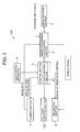
- the aforementioned distance detecting section 8 is disused, while a fill light emitting section 102 is provided.
- the fill light emitting section 102 includes a light source for white light, red light, and the like and its driving circuit, and emits a fill light for imaging as required.
- the control 2 functions as an autofocusing section 23 of the present invention and the other components are the same as those of FIG. 1 and the same reference numerals are added to the same parts as those of FIG. 1, and the explanation is omitted.
- FIG. 4 is a flowchart illustrating an operation of the projector 101 after power is turned on.
- the control section 2 drives the projector lens 62 and the imaging lens 71 to initialize each zoom ratio (step SB1), and then starts projecting a document, an image, and the like (step SB2).
- steps SB5 to SB 11 are the same as those explained in steps SA5 to SA11 shown in FIG. 2.
- the zoom ratio of the imaging lens 71 may be controlled immediately before the imaging operation only when the shooting operation is executed by the user. Furthermore, the focus control of the projector lens 62 and the imaging lens 71 except the adjustment with the change in the zoom ratio may be performed just after power is turned on.
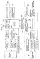
- FIG. 5 is a block diagram illustrating a schematic configuration of a projector 201 according to this embodiment.
- the projector 201 includes a projecting section 206 having a display section 61, a projector lens 62 and a lens position detecting section 207 unlike the aforementioned projectors 1 and 101.
- the display section 61 is the same as that previously explained, and the projector lens 62 is also the same as that previous explained except the point that the change in zoom ratio and focus adjustment are manually executed.
- the lens position detecting section 207 includes a position sensor that detects each lens position of the projector lens 62 moved by the manual operation, and sends a position detection signal indicating each position to the control section 2. Additionally, regarding the other configuration, the same reference numerals are added to the same parts as those of FIGS. 1 and 2 and the explanation is omitted.
- FIG. 6 is a flowchart illustrating an operation of the projector 201 after power is turned on.
- the control section 2 first starts projecting a document, an image and the like (step SC1).
- the control section 2 obtains a zoom ratio of the projector lens 62 and a projection distance based on lens position information detected by the lens position detecting section 207 (step SC2). Additionally, in order to obtain the zoom ratio and the projection distance, the aforementioned focus setting table for projector lens 62 is used.
- control section 2 controls a zoom ratio of the imaging lens 71 to a zoom ratio corresponding to the zoom ratio of the projector lens 62 by using the aforementioned zoom ratio setting table based on the obtained zoom ratio and projection distance, and controls a focus of the imaging lens 71 by regarding the projection distance as a subject distance, and using the aforementioned focus setting table (step SC3).
- the zoom ratio of the imaging lens 71 is controlled to the zoom ratio, which is synchronized with the zoom ratio of the projector lens 62 and corresponds to the zoom ratio of the projector lens 62, and the focus position is automatically controlled. Therefore, also, in this embodiment, at the time of shooting the screen on which the image is projected, there is no need to perform the work for individually changing and adjusting the zoom ratio and the focus of the imaging lens 71. This makes it possible to improve the usability and facilitate the work for shooting the screen on which the image is projected.
- the explanation is given of the imaging lens 71, which is focus controllable.
- the zoom ratio of the imaging lens 71 is only synchronized with the zoom ratio of the projector lens 62, thereby making it possible to eliminate the need for the preparatory work prior to the use of a shooting function and improve the usability.
- FIG. 7 is a block diagram illustrating a schematic configuration of a projection image shooting system according to the present invention.
- the projection image shooting system of this embodiment includes a projector 301 and a digital camera 401 that are connected to each other via a USB cable 501.
- the projector 301 has a USB interface 302, which is a transmitting section of the present invention, thereby making it possible to perform data communications with the digital camera 401. Furthermore, in a program ROM 21 (not shown) that configures the control section 2, a program for causing the projector 301 to execute an operation to be described later is stored.
- the digital camera 401 is an imaging apparatus of the present invention, and includes an imaging lens 71, an image sensor 72, a signal processing section 73, a focus motor 74, a zoom motor 75, and a motor drive control section 76, which have the same functions as those provided in the camera section 7 of the projector 1 shown in FIG. 1 as the first embodiment. Additionally, in FIG. 7, a driving circuit that drives the image sensor 72 is also omitted.
- the image recording section 405 is a nonvolatile memory that records an image imaged by the image sensor 72, and constituted by, for example, a flash memory that is built in the main body of the camera or attachable/detachable to/from the main body of the camera.
- the display section 403 is constituted by a liquid crystal monitor, which displays the image imaged by the image sensor 72 and the image recorded on the image recording section 405, and its driving circuit.
- the DRAM 404 is used as a work memory mainly when the control section 408 performs compression/decompression of the image imaged by the image sensor 72.
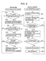
- FIG. 8 is a flowchart illustrating an operation when projection is executed in a sync projecting mode by the projector 301 and an operation when a sync shooting mode is set by the digital camera 401.
- the sync projecting mode of the projector 301 is a mode, which is automatically set when the digital camera 401 is connected thereto at the time when power is turned on or the digital camera 401 is connected thereto at an arbitrary time after power is turned on.
- the sync shooting mode of the digital camera 401 is a shooting operation mode which is settable, for example, only when the digital camera 401 is connected to the projector 301, and is set with a user's mode setting operation.
- the control section 2 of the projector 301 in the sync projecting mode projects an image with an arbitrary zoom ratio set by the user's operation from the user control apparatus 5, and automatically controls a focus by an AF function that the projector 301 possesses. Then, when a transmission request for angle-of-view information is sent from the digital camera 401 (YES in step SE1), the control section 2 transmits the zoom ratio obtained at this time to the digital camera 401 as angle-of-view information (step SE2).
- the control section 2 of the projector 301 drives the zoom lens of the projector lens 62 to change the zoom ratio accordingly, and stores angle-of-view information changed according to the change of the zoom ratio (step SE4).
- the control section 2 transmits the changed angle-of-view information to the digital camera 401 (step SE6).
- step SE5 if the angle-of-view information is not yet sent to the digital camera 401 (NO in step SE5), the processing flow directly goes back to step SE1 and the aforementioned processing is repeated. Namely, after the angle-of-view information is once transmitted in accordance with the transmission request from the digital camera 401, the control section 2 automatically transmits a changed zoom ratio to the digital camera 401 every time when a change operation in angle of view is executed.
- step SD5 the digital camera 401 enters the wait state of a shooting operation by a user, and if no shooting operation is executed (NO in step SD5), the control section 408 goes back to step SD3. Then, during the wait state of the shooting operation, every time when angle-of-view information is received from the projector 301, the control section 408 changes the zoom ratio of the imaging lens 71 according to the reception of angle-of-view information.
- step SD6 the control section 408 executes imaging processing using a screen on which a document, an image and the like are projected as a subject
- step SD7 the processing flow goes back to step SD3 and the aforementioned operation is repeated until the sync shooting mode is released.
- the angle of view of the digital camera 401 is automatically controlled to an optimal angle of view corresponding to the angle of view of the projector 301 in synchronization with the adjustment of the angle of view of the projector 301.
- the shooting direction (direction of an optical axis of the imaging lens 71) is substantially adjusted to the projection direction (optical axis of the projector lens 62) of the projector 301 in advance as confirming the through image displayed on the display section 403 after setting the general recording mode to the digital camera 401.
- transmission and reception of angle-of-view information between the projector 301 and the digital camera 401 is allowed by USB connection.
- the zoom ratio setting table indicating an optimal zoom ratio corresponding to the relationship between the zoom ratio of the projector lens 62 possessed by the projector 301 and the distance up to the screen (projection distance, subject distance).
- data forming a zoom ratio setting table may be obtained from the projector 301 at the time when the aforementioned sync shooting mode is set.
- data corresponding to the model of the digital camera 401 should be prepared in the projector 301.
Landscapes
- Physics & Mathematics (AREA)
- General Physics & Mathematics (AREA)
- Engineering & Computer Science (AREA)
- Multimedia (AREA)
- Signal Processing (AREA)
- Projection Apparatus (AREA)
- Automatic Focus Adjustment (AREA)
- Transforming Electric Information Into Light Information (AREA)
- Cameras Adapted For Combination With Other Photographic Or Optical Apparatuses (AREA)
- Studio Devices (AREA)
- Lens Barrels (AREA)
Applications Claiming Priority (2)
| Application Number | Priority Date | Filing Date | Title |
|---|---|---|---|
| JP2003351429A JP3764976B2 (ja) | 2003-10-10 | 2003-10-10 | 撮影機能付投射装置、及び投射画像撮影システム |
| JP2003351429 | 2003-10-10 |
Publications (3)
| Publication Number | Publication Date |
|---|---|
| EP1523177A2 true EP1523177A2 (de) | 2005-04-13 |
| EP1523177A3 EP1523177A3 (de) | 2008-02-13 |
| EP1523177B1 EP1523177B1 (de) | 2017-05-10 |
Family
ID=34309262
Family Applications (1)
| Application Number | Title | Priority Date | Filing Date |
|---|---|---|---|
| EP04023932.9A Expired - Lifetime EP1523177B1 (de) | 2003-10-10 | 2004-10-07 | Projektor mit Aufzeichnungsvorrichtung |
Country Status (5)
| Country | Link |
|---|---|
| US (1) | US7092028B2 (de) |
| EP (1) | EP1523177B1 (de) |
| JP (1) | JP3764976B2 (de) |
| KR (1) | KR100610557B1 (de) |
| CN (1) | CN100395650C (de) |
Families Citing this family (23)
| Publication number | Priority date | Publication date | Assignee | Title |
|---|---|---|---|---|
| JP4379728B2 (ja) * | 2005-01-31 | 2009-12-09 | カシオ計算機株式会社 | 撮像装置及びそのプログラム |
| US7522198B2 (en) * | 2005-04-20 | 2009-04-21 | Nokia Corporation | Electronic device, a method and a program product for determining a show zoom ratio for an image |
| JP4670545B2 (ja) * | 2005-08-16 | 2011-04-13 | 富士ゼロックス株式会社 | 画像撮影装置 |
| JP2007078821A (ja) * | 2005-09-12 | 2007-03-29 | Casio Comput Co Ltd | 投影装置、投影方法及びプログラム |
| JP4662054B2 (ja) * | 2006-01-20 | 2011-03-30 | 株式会社リコー | 撮像装置 |
| JP2008111912A (ja) * | 2006-10-30 | 2008-05-15 | Nikon Corp | カメラ |
| US20080158669A1 (en) * | 2006-12-29 | 2008-07-03 | 3M Innovative Properties Company | Projection screen apparatus for use with portable digital projectors |
| JP2009272921A (ja) * | 2008-05-08 | 2009-11-19 | Panasonic Corp | 動画像記録装置、動画像再生装置、動画像記録方法、動画像再生方法および半導体集積回路 |
| JP5310266B2 (ja) * | 2009-05-29 | 2013-10-09 | セイコーエプソン株式会社 | プロジェクターおよびその制御方法 |
| JP4983752B2 (ja) * | 2008-09-08 | 2012-07-25 | セイコーエプソン株式会社 | 光源駆動方法およびプロジェクタ |
| JP5200800B2 (ja) * | 2008-09-16 | 2013-06-05 | 富士ゼロックス株式会社 | 撮影装置及び撮影システム |
| JP5276943B2 (ja) * | 2008-09-29 | 2013-08-28 | 株式会社日立製作所 | 表示装置 |
| DE202011111062U1 (de) | 2010-01-25 | 2019-02-19 | Newvaluexchange Ltd. | Vorrichtung und System für eine Digitalkonversationsmanagementplattform |
| US9064312B2 (en) * | 2011-09-23 | 2015-06-23 | The Regents Of The University Of California | Augmented reality using projector-camera enabled devices |
| TWI511551B (zh) * | 2012-04-12 | 2015-12-01 | Acer Inc | 攝影裝置及其影像拍攝方法 |
| CN203012332U (zh) * | 2012-11-30 | 2013-06-19 | 神画科技(深圳)有限公司 | 带红外监控的投影系统 |
| KR20150115455A (ko) | 2014-04-04 | 2015-10-14 | 삼성전자주식회사 | 휴대단말기의 프로젝터 초점 제어 방법 및 장치 |
| US20150305087A1 (en) * | 2014-04-18 | 2015-10-22 | de Blake | Automatically Adjustable Projector with Wireless Data Stream |
| JP6878816B2 (ja) * | 2016-01-20 | 2021-06-02 | セイコーエプソン株式会社 | プロジェクター |
| CN108398845A (zh) * | 2018-02-02 | 2018-08-14 | 北京小米移动软件有限公司 | 投影设备控制方法和投影设备控制装置 |
| CN109451289B (zh) * | 2018-12-25 | 2019-12-27 | 鸿视线科技(北京)有限公司 | 对投影仪进行检测和校正的方法和系统 |
| CN114424118A (zh) | 2019-07-09 | 2022-04-29 | 麦克赛尔株式会社 | 投射型影像显示装置 |
| CN112822467B (zh) * | 2019-11-15 | 2022-11-29 | 中强光电股份有限公司 | 投影装置及其自动对焦方法 |
Citations (2)
| Publication number | Priority date | Publication date | Assignee | Title |
|---|---|---|---|---|
| JPH0419235A (ja) | 1990-05-11 | 1992-01-23 | Iseki & Co Ltd | トラクタの走行駆動制御装置 |
| US5796425A (en) | 1995-05-16 | 1998-08-18 | Mitsubishi Denki Kabushiki Kaisha | Elimination of the effect of difference in vertical scanning frequency between a display and a camera imaging the display |
Family Cites Families (10)
| Publication number | Priority date | Publication date | Assignee | Title |
|---|---|---|---|---|
| ATE105988T1 (de) * | 1988-10-05 | 1994-06-15 | Wolf Josef Audio Visuals | Gerät und verfahren für das umwandeln von bildern oder abbildern in videosignale. |
| JPH04109235A (ja) * | 1990-06-11 | 1992-04-10 | Akai Electric Co Ltd | 投影機 |
| JPH11305335A (ja) | 1998-04-20 | 1999-11-05 | Minolta Co Ltd | プレゼンテーションシステム |
| JP4534285B2 (ja) * | 1999-12-28 | 2010-09-01 | 株式会社ニコン | 画像入出力装置 |
| JP4961628B2 (ja) * | 2000-08-11 | 2012-06-27 | 日本電気株式会社 | 投射映像補正システム及びその方法 |
| JP4533566B2 (ja) * | 2001-09-21 | 2010-09-01 | 株式会社リコー | 書込み可能な表示装置 |
| JP3744402B2 (ja) * | 2001-10-16 | 2006-02-08 | セイコーエプソン株式会社 | 光学装置の製造方法、および基準位置出し原器 |
| JP2003131319A (ja) * | 2001-10-25 | 2003-05-09 | Seiko Epson Corp | 光送受装置 |
| TW200412469A (en) * | 2003-01-02 | 2004-07-16 | Lite On Technology Corp | Automatically focusing method for projector and projector using this method |
| US7234819B2 (en) * | 2003-09-30 | 2007-06-26 | Olympus Corporation | Projector system and camera system |
-
2003
- 2003-10-10 JP JP2003351429A patent/JP3764976B2/ja not_active Expired - Fee Related
-
2004
- 2004-10-04 US US10/957,859 patent/US7092028B2/en not_active Expired - Lifetime
- 2004-10-07 EP EP04023932.9A patent/EP1523177B1/de not_active Expired - Lifetime
- 2004-10-08 KR KR1020040080166A patent/KR100610557B1/ko not_active Expired - Fee Related
- 2004-10-10 CN CNB2004100809525A patent/CN100395650C/zh not_active Expired - Fee Related
Patent Citations (2)
| Publication number | Priority date | Publication date | Assignee | Title |
|---|---|---|---|---|
| JPH0419235A (ja) | 1990-05-11 | 1992-01-23 | Iseki & Co Ltd | トラクタの走行駆動制御装置 |
| US5796425A (en) | 1995-05-16 | 1998-08-18 | Mitsubishi Denki Kabushiki Kaisha | Elimination of the effect of difference in vertical scanning frequency between a display and a camera imaging the display |
Also Published As
| Publication number | Publication date |
|---|---|
| CN1605926A (zh) | 2005-04-13 |
| EP1523177A3 (de) | 2008-02-13 |
| CN100395650C (zh) | 2008-06-18 |
| KR100610557B1 (ko) | 2006-08-10 |
| JP2005115185A (ja) | 2005-04-28 |
| JP3764976B2 (ja) | 2006-04-12 |
| US20050078203A1 (en) | 2005-04-14 |
| EP1523177B1 (de) | 2017-05-10 |
| US7092028B2 (en) | 2006-08-15 |
| KR20050035089A (ko) | 2005-04-15 |
Similar Documents
| Publication | Publication Date | Title |
|---|---|---|
| EP1523177B1 (de) | Projektor mit Aufzeichnungsvorrichtung | |
| EP2074829B1 (de) | Projektionsvorrichtung und optische abstandsmessung | |
| US7070283B2 (en) | Projection apparatus, projection method and recording medium recording the projection method | |
| CN102455575B (zh) | 投影型显示装置及其控制方法 | |
| US20060061663A1 (en) | Digital camera with touch screen display panel usable as remote controller and method of operating the digital camera | |
| US9609227B2 (en) | Photographing apparatus, image pickup and observation apparatus, image comparison and display method, image comparison and display system, and recording medium | |
| US20070201851A1 (en) | Imaging apparatus | |
| EP2461592A2 (de) | Zeitlösung für Projektorkameravorrichtungen und Systeme | |
| JP2004274283A (ja) | 投影システム、及び投影装置、画像供給装置、プログラム | |
| CN104954667A (zh) | 显示设备和显示方法 | |
| JP4150295B2 (ja) | 投射型画像表示装置 | |
| KR20130004977A (ko) | 하이브리드 3차원 스캐너 | |
| JP3925548B2 (ja) | 撮影機能付投射装置、及び投射画像撮影システム | |
| JP2005031235A (ja) | 写真撮影装置 | |
| JP2006201494A (ja) | プロジェクタ装置 | |
| KR20130121526A (ko) | 착용형 프로젝션 장치 | |
| JP2014007484A (ja) | 補正制御装置、補正方法、及び、プロジェクター | |
| JP2002281349A (ja) | 書画カメラ | |
| JP2017121076A (ja) | 補正制御装置、補正方法、及び、プロジェクター | |
| JP6701925B2 (ja) | 画像供給装置、画像供給装置の制御方法、及び、プログラム | |
| KR102149508B1 (ko) | 촬영 장치, 그 제어 방법, 및 컴퓨터 판독가능 기록매체 | |
| JP2012027302A (ja) | 投影機能付き撮像装置 | |
| US20060067680A1 (en) | Portable image capturing device | |
| KR20150116688A (ko) | 휴대형 소형 레이저 프로젝터 | |
| JP2001208954A (ja) | デジタルカメラ |
Legal Events
| Date | Code | Title | Description |
|---|---|---|---|
| PUAI | Public reference made under article 153(3) epc to a published international application that has entered the european phase |
Free format text: ORIGINAL CODE: 0009012 |
|
| 17P | Request for examination filed |
Effective date: 20041007 |
|
| AK | Designated contracting states |
Kind code of ref document: A2 Designated state(s): AT BE BG CH CY CZ DE DK EE ES FI FR GB GR HU IE IT LI LU MC NL PL PT RO SE SI SK TR |
|
| AX | Request for extension of the european patent |
Extension state: AL HR LT LV MK |
|
| PUAL | Search report despatched |
Free format text: ORIGINAL CODE: 0009013 |
|
| AK | Designated contracting states |
Kind code of ref document: A3 Designated state(s): AT BE BG CH CY CZ DE DK EE ES FI FR GB GR HU IE IT LI LU MC NL PL PT RO SE SI SK TR |
|
| AX | Request for extension of the european patent |
Extension state: AL HR LT LV MK |
|
| AKX | Designation fees paid |
Designated state(s): DE FR GB |
|
| 17Q | First examination report despatched |
Effective date: 20091130 |
|
| GRAP | Despatch of communication of intention to grant a patent |
Free format text: ORIGINAL CODE: EPIDOSNIGR1 |
|
| GRAJ | Information related to disapproval of communication of intention to grant by the applicant or resumption of examination proceedings by the epo deleted |
Free format text: ORIGINAL CODE: EPIDOSDIGR1 |
|
| INTG | Intention to grant announced |
Effective date: 20161116 |
|
| RAP1 | Party data changed (applicant data changed or rights of an application transferred) |
Owner name: CASIO COMPUTER CO., LTD. |
|
| INTC | Intention to grant announced (deleted) | ||
| GRAP | Despatch of communication of intention to grant a patent |
Free format text: ORIGINAL CODE: EPIDOSNIGR1 |
|
| INTG | Intention to grant announced |
Effective date: 20170130 |
|
| GRAS | Grant fee paid |
Free format text: ORIGINAL CODE: EPIDOSNIGR3 |
|
| GRAA | (expected) grant |
Free format text: ORIGINAL CODE: 0009210 |
|
| AK | Designated contracting states |
Kind code of ref document: B1 Designated state(s): DE FR GB |
|
| REG | Reference to a national code |
Ref country code: GB Ref legal event code: FG4D |
|
| REG | Reference to a national code |
Ref country code: DE Ref legal event code: R096 Ref document number: 602004051223 Country of ref document: DE |
|
| REG | Reference to a national code |
Ref country code: FR Ref legal event code: PLFP Year of fee payment: 14 |
|
| REG | Reference to a national code |
Ref country code: DE Ref legal event code: R097 Ref document number: 602004051223 Country of ref document: DE |
|
| PLBE | No opposition filed within time limit |
Free format text: ORIGINAL CODE: 0009261 |
|
| STAA | Information on the status of an ep patent application or granted ep patent |
Free format text: STATUS: NO OPPOSITION FILED WITHIN TIME LIMIT |
|
| 26N | No opposition filed |
Effective date: 20180213 |
|
| REG | Reference to a national code |
Ref country code: FR Ref legal event code: PLFP Year of fee payment: 15 |
|
| PGFP | Annual fee paid to national office [announced via postgrant information from national office to epo] |
Ref country code: FR Payment date: 20180913 Year of fee payment: 15 |
|
| PGFP | Annual fee paid to national office [announced via postgrant information from national office to epo] |
Ref country code: DE Payment date: 20180925 Year of fee payment: 15 |
|
| PGFP | Annual fee paid to national office [announced via postgrant information from national office to epo] |
Ref country code: GB Payment date: 20181003 Year of fee payment: 15 |
|
| REG | Reference to a national code |
Ref country code: DE Ref legal event code: R119 Ref document number: 602004051223 Country of ref document: DE |
|
| PG25 | Lapsed in a contracting state [announced via postgrant information from national office to epo] |
Ref country code: DE Free format text: LAPSE BECAUSE OF NON-PAYMENT OF DUE FEES Effective date: 20200501 |
|
| GBPC | Gb: european patent ceased through non-payment of renewal fee |
Effective date: 20191007 |
|
| PG25 | Lapsed in a contracting state [announced via postgrant information from national office to epo] |
Ref country code: FR Free format text: LAPSE BECAUSE OF NON-PAYMENT OF DUE FEES Effective date: 20191031 Ref country code: GB Free format text: LAPSE BECAUSE OF NON-PAYMENT OF DUE FEES Effective date: 20191007 |