EP1523026A2 - Elektronenemitter - Google Patents
Elektronenemitter Download PDFInfo
- Publication number
- EP1523026A2 EP1523026A2 EP04255292A EP04255292A EP1523026A2 EP 1523026 A2 EP1523026 A2 EP 1523026A2 EP 04255292 A EP04255292 A EP 04255292A EP 04255292 A EP04255292 A EP 04255292A EP 1523026 A2 EP1523026 A2 EP 1523026A2
- Authority
- EP
- European Patent Office
- Prior art keywords
- emitter
- electrode
- voltage
- electron
- electrons
- Prior art date
- Legal status (The legal status is an assumption and is not a legal conclusion. Google has not performed a legal analysis and makes no representation as to the accuracy of the status listed.)
- Granted
Links
Images











Classifications
-
- G—PHYSICS
- G09—EDUCATION; CRYPTOGRAPHY; DISPLAY; ADVERTISING; SEALS
- G09G—ARRANGEMENTS OR CIRCUITS FOR CONTROL OF INDICATING DEVICES USING STATIC MEANS TO PRESENT VARIABLE INFORMATION
- G09G3/00—Control arrangements or circuits, of interest only in connection with visual indicators other than cathode-ray tubes
- G09G3/20—Control arrangements or circuits, of interest only in connection with visual indicators other than cathode-ray tubes for presentation of an assembly of a number of characters, e.g. a page, by composing the assembly by combination of individual elements arranged in a matrix no fixed position being assigned to or needed to be assigned to the individual characters or partial characters
- G09G3/22—Control arrangements or circuits, of interest only in connection with visual indicators other than cathode-ray tubes for presentation of an assembly of a number of characters, e.g. a page, by composing the assembly by combination of individual elements arranged in a matrix no fixed position being assigned to or needed to be assigned to the individual characters or partial characters using controlled light sources
-
- B—PERFORMING OPERATIONS; TRANSPORTING
- B82—NANOTECHNOLOGY
- B82Y—SPECIFIC USES OR APPLICATIONS OF NANOSTRUCTURES; MEASUREMENT OR ANALYSIS OF NANOSTRUCTURES; MANUFACTURE OR TREATMENT OF NANOSTRUCTURES
- B82Y10/00—Nanotechnology for information processing, storage or transmission, e.g. quantum computing or single electron logic
-
- H—ELECTRICITY
- H01—ELECTRIC ELEMENTS
- H01J—ELECTRIC DISCHARGE TUBES OR DISCHARGE LAMPS
- H01J1/00—Details of electrodes, of magnetic control means, of screens, or of the mounting or spacing thereof, common to two or more basic types of discharge tubes or lamps
- H01J1/02—Main electrodes
- H01J1/30—Cold cathodes, e.g. field-emissive cathode
- H01J1/312—Cold cathodes, e.g. field-emissive cathode having an electric field perpendicular to the surface, e.g. tunnel-effect cathodes of metal-insulator-metal [MIM] type
-
- H—ELECTRICITY
- H01—ELECTRIC ELEMENTS
- H01J—ELECTRIC DISCHARGE TUBES OR DISCHARGE LAMPS
- H01J31/00—Cathode ray tubes; Electron beam tubes
- H01J31/08—Cathode ray tubes; Electron beam tubes having a screen on or from which an image or pattern is formed, picked up, converted, or stored
- H01J31/10—Image or pattern display tubes, i.e. having electrical input and optical output; Flying-spot tubes for scanning purposes
- H01J31/12—Image or pattern display tubes, i.e. having electrical input and optical output; Flying-spot tubes for scanning purposes with luminescent screen
- H01J31/123—Flat display tubes
- H01J31/125—Flat display tubes provided with control means permitting the electron beam to reach selected parts of the screen, e.g. digital selection
- H01J31/127—Flat display tubes provided with control means permitting the electron beam to reach selected parts of the screen, e.g. digital selection using large area or array sources, i.e. essentially a source for each pixel group
-
- H—ELECTRICITY
- H01—ELECTRIC ELEMENTS
- H01J—ELECTRIC DISCHARGE TUBES OR DISCHARGE LAMPS
- H01J63/00—Cathode-ray or electron-stream lamps
- H01J63/02—Details, e.g. electrode, gas filling, shape of vessel
-
- H—ELECTRICITY
- H01—ELECTRIC ELEMENTS
- H01J—ELECTRIC DISCHARGE TUBES OR DISCHARGE LAMPS
- H01J2201/00—Electrodes common to discharge tubes
- H01J2201/30—Cold cathodes
- H01J2201/312—Cold cathodes having an electric field perpendicular to the surface thereof
- H01J2201/3125—Metal-insulator-Metal [MIM] emission type cathodes
Definitions
- the present invention relates to an electron emitter having a first electrode and a second electrode which are formed on a substance serving as an emitter.
- FEDs field emission displays
- a plurality of electron emitters are arranged in a two-dimensional array, and a plurality of phosphors are positioned in association with the respective electron emitters with a predetermined gap left therebetween.
- an upper electrode 204 and a lower electrode 206 are formed on a substance (emitter) 202 serving as an emitter in a conventional electron emitter 200
- the upper electrode 204 in particular is formed in intimate contact with the emitter 202.
- a point where electric field concentrates is a triple point made up of the upper electrode 204, the emitter 202, and the vacuum, and corresponds to a peripheral edge portion of the upper electrode 204.
- the peripheral edge portion of the upper electrode 204 is held in intimate contact with the emitter 202, the arrangement suffers a problem in that the degree of electric field concentration is small and the energy required to emit electrons is small. Furthermore, because an electron emission region is limited to the peripheral edge portion of the upper electrode 204, the overall electron emission characteristics tend to vary, making it difficult to control the emission of electrons and also making the electron emission efficiency low.
- the present invention has been made in view of the above drawbacks. It is an object of the present invention to provide an electron emitter which is capable of easily producing a high electric field concentration, providing many electron emission regions, emitting electrons with a large output and a high efficiency, and being driven at a low voltage.
- Another object of the present invention to provide an electron emitter which can easily be applied to a display having a plurality of electron emitters arrayed in association with a plurality of pixels, for emitting electrons from the electron emitters to display an image.
- An electron emitter is characterized by a substance serving as an emitter made of a dielectric material, and a first electrode and a second electrode to which a drive voltage is applied to emit electrons, the first electrode being formed on a first surface of the substance serving as the emitter, the second electrode being formed on a second surface of the substance serving as the emitter, at least the first electrode having a plurality of through regions through which the substance serving as the emitter is exposed, the first electrode having a surface which faces the substance serving as the emitter in peripheral portions of the through regions and which is spaced from the substance serving as the emitter.
- a drive voltage is applied between the first electrode and the second electrode.
- the drive voltage is defined as a voltage, such as a pulse voltage or an alternating-current voltage, which abruptly changes, with time, from a voltage level higher or lower than a reference voltage (e.g., 0 V) to a voltage level that is lower or higher than the reference voltage.
- a reference voltage e.g. 0 V
- a triple junction is formed in a region of contact between the first surface of the substance serving as the emitter, the first electrode, and a medium (e.g., a vacuum) around the electron emitter.
- the triple junction is defined as an electric field concentration region formed by a contact between the first electrode, the substance serving as the emitter, and the vacuum.
- the triple junction includes a triple point where the first electrode, the substance serving as the emitter, and the vacuum exist as one point.
- the triple junction is formed the peripheral portions of the through regions and the peripheral area of the first electrode. Therefore, when the drive voltage is applied between the first electrode and the second electrode, an electric field concentration occurs at the triple junction.
- a period for outputting the voltage level higher or lower than the reference voltage is referred to as a first output period, and a period for outputting the voltage level lower or higher than the reference voltage as a second output period.
- the first output period an electric field concentration occurs at the triple junction; accumulating electrons in the portions of the substance serving as the emitter which correspond to the through regions of the first electrode and regions near the peripheral portion of the first electrode.
- the first electrode functions as an electron supply source.
- the electron emitter in a first output period, is prepared for electron emission (e.g., the substance serving as the emitter is polarized in one direction).
- a next second output period when the voltage level of the drive voltage is quickly changed, an electric field concentration occurs at the triple junction, causing the first electrode to emit primary electrons, which impinge upon the portions of the substance serving as the emitter which are exposed through the through regions and the regions near the outer peripheral portion of the first electrode.
- Secondary electrons (including reflected primary electrons) are emitted from the portions hit by the primary electrons.
- secondary electrons are emitted from the through regions and the regions near the outer peripheral portion of the first electrode in an initial stage of the second output period.
- the first electrode of the electron emitter has the plural through regions, electrons are uniformly emitted from each of the through regions and the outer peripheral portions of the first electrode. Thus, any variations in the overall electron emission characteristics of the electron emitter are reduced, making it possible to facilitate the control of the electron emission and increase the electron emission efficiency.
- the present invention furthermore, because a gap is formed between the surface of the first electrode which faces the substance serving as the emitter in the peripheral portions of the through regions and the substance serving as the emitter, when the drive voltage is applied, an electric field concentration tends to be produced in the region of the gap. This leads to a higher efficiency of the electron emission, making the drive voltage lower (emitting electrons at a lower voltage level).
- the gap is formed between the surface of the first electrode which faces the substance serving as the emitter in the peripheral portions of the through regions and the substance serving as the emitter, providing overhanging portions (flanges) on the peripheral portions of the through regions, electrons are easily emitted from the overhanging portions (the peripheral portions of the through regions) of the first electrode, also with the increased electric field concentration in the region of the gap. This leads to a larger output and higher efficiency of the electron emission, making the drive voltage lower.
- the straightness of emitted electrons can be increased. This is effective in reducing crosstalk if a number of electron emitters are arrayed for use as an electron source of a display.
- the electron emitter according to the present invention is capable of easily developing a high electric field concentration, provides many electron emission regions, has a larger output and higher efficiency of the electron emission, and can be driven at a lower voltage (lower power consumption).
- At least the first surface of the substance serving as the emitter may have surface irregularities due to the grain boundary of the dielectric material, and the through regions of the first electrode may be formed in regions corresponding to concavities of the surface irregularities due to the grain boundary of the dielectric material.
- the structure in which the surface of the first electrode which faces the substance serving as the emitter in the peripheral portions of the through regions i.e., the structure in which the gap is formed between the surface of the first electrode which faces the substance serving as the emitter in the peripheral portions of the through regions and the substance serving as the emitter, can simply be achieved.
- a floating electrode may exist in regions of the first surface of the substance serving as the emitter which correspond to the through regions.
- the floating electrode also serves as an electron supply source, a number of electrons can be emitted out through the through regions in the electron emission stage (the second output period referred to above).
- the through regions may comprise holes.
- the portions of the substance serving as the emitter where the polarization is inverted or changed depending on the drive voltage applied between the first electrode and the second electrode include a portion (first portion) directly below the first electrode and a portion (second portion) corresponding to a region extending from the inner peripheral edges of the through regions inwardly of the through regions.
- the second portion changes depending on the level of the drive voltage and the degree of the electric field concentration.
- the average diameter of the holes should preferably be is in the range from 0.1 ⁇ m to 10 ⁇ m. Insofar as the average diameter of the holes is in this range, the distribution of electrons emitted through the through regions is almost free of any variations, allowing electrons to be emitted efficiently.
- the average diameter of the hole is less than 0.1 ⁇ m, then the region where electrons are accumulated is made narrower, reducing the amount of emitted electrons. While one solution would be to form many holes, it would be difficult and highly costly to form many holes. If the average diameter of the holes is in excess of 10 ⁇ m, then the proportion (share) of the portion (second portion) which contributes to the emission of electrons in the portion of the substance serving as the emitter that is exposed through the through regions is reduced, resulting in a reduction in the electron emission efficiency.
- the through regions may comprise recesses or comb-toothed recesses.
- the recesses should preferably have an average width in the range from 0.1 ⁇ m to 10 ⁇ m.
- the through regions may comprise slits having an optional shape.
- the slits should preferably have an average width in the range from 0.1 ⁇ m to 10 ⁇ m.
- An electron emitter is characterized by a substance serving as an emitter made of a dielectric material, a first electrode formed in contact with a first surface of the substance serving as the emitter, a second electrode formed in contact with a second surface of the substance serving as the emitter, and at least the first electrode having a plurality of through regions through which the substance serving as the emitter is exposed, wherein the electron emitter has, in its electrical operation, between the first electrode and the second electrode, a capacitor due to the substance serving as the emitter, and a cluster of capacitors formed the first electrode and the substance serving as the emitter by the through regions of the first electrode.
- Gaps are formed between the surface which faces the substance serving as the emitter in the peripheral portions of the through regions and the substance serving as the emitter, and the cluster of capacitors is formed by these gaps.
- the capacitance of the cluster of capacitors due to the gaps is relatively small. Because of the voltage division between the cluster of capacitors and the capacitor due to the substance serving as the emitter, almost the entire applied voltage is applied across the gaps, which are effective to produce a larger output of the electron emission. Since the cluster of capacitors is connected in series to the capacitor due to the substance serving as the emitter, the overall capacitance is smaller than the capacitance of the capacitor due to the substance serving as the emitter. This is effective to provide such preferred characteristics that the electron emission is performed for a larger output and the overall power consumption is lower.
- An electron emitter having an electron emission region is characterized in that if the electron emitter changes to a state (first state) in which an amount of positive charges and an amount of negative charges due to the accumulation of electrons caused by applying a negative voltage are in equilibrium with each other, and changes to a state (second state) in which an amount of negative charges is greater than an amount of positive charges due to the accumulation of further electrons, and if the electron emitter changes from the second state to a state (third state) in which an amount of positive charges and an amount of negative charges due to the emission of electrons caused by applying a positive voltage are in equilibrium with each other, and changes to a state (fourth state) in which an amount of positive charges is greater than an amount of negative charges due to the emission of further electrons, then the electron emission has characteristics represented by:
- the voltages may be related to each other by 1.5 ⁇
- the period in which to display one image is defined as one frame
- all the electron emitters are scanned, and accumulating voltages depending on the luminance levels of corresponding pixels are applied to a plurality of electron emitters which correspond to pixels to be turned on, thereby charges in amounts depending on the luminance levels of the corresponding pixels in the electron emitters which correspond to the pixels to be turned on.
- a constant voltage is applied to all the electron emitters to cause the electron emitters which correspond to the pixels to be turned on to emit electrons in amounts depending on the luminance levels of the corresponding pixels, thereby emitting light from the pixels to be turned on.
- the rates may be related to each other by: ( ⁇ Q1/ ⁇ V1) > ( ⁇ Q2/ ⁇ V2).
- V3 a voltage at which the accumulation of electrons is saturated
- a voltage at which the emission of electrons is started by V4
- the voltages may have characteristics: 1 ⁇
- the electron emitters are arranged in a matrix and selected row by row in synchronism with a horizontal scanning period, and pixel signals depending on the luminance levels of pixels are supplied to the selected electron emitters, the pixel signals are also supplied to unselected pixels.
- the unselected electron emitters are affected by the pixel signals and emit electrons, then problems arise in that the quality of displayed images is degraded and the contrast thereof is lowered.
- the voltage levels of the pixel signals supplied to the selected electron emitters are set to desired voltages in the range from the reference voltage to the voltage V3 and signals that are of opposite polarity to the pixel signals, for example, are supplied to unselected electron emitters, the unselected pixels are not affected by the pixel signals supplied to the selected pixels, and a memory effect is achieved at each pixel for higher luminance and higher contrast.
- An electron emitter is characterized by a substance serving as an emitter made of a dielectric material, and a first electrode and a second electrode to which a drive voltage is applied to emit electrons, wherein if a voltage applied in one direction between the first electrode and the second electrode to change the electron emitter from a state in which the substance serving as the emitter is polarized in one direction to a state in which the polarization is inverted is referred to as a first coercive voltage v1, and a voltage applied in another direction to change the polarization back in the one direction from the last-mentioned state is referred to as a second coercive voltage v2, then the voltages are related to each other by: v1 ⁇ 0 or v2 ⁇ 0, and
- the voltages may have characteristics: 1.5 ⁇
- the rates may be related to each other by: ( ⁇ q1/ ⁇ v1) > ( ⁇ q2/ ⁇ v2).
- the voltages may have characteristics: 1 ⁇
- the electron emitter to a display having a plurality of electron emitters arrayed in association with respective pixels for emitting electrons from the electron emitters to display an image.
- unselected pixels are not affected by signals supplied to selected pixels, and a memory effect is achieved at each pixel for higher luminance and higher contrast.
- the electron emitter according to the present invention is capable of easily developing a high electric field concentration, provides many electron emission regions, has a larger output and higher efficiency of the electron emission, and can be driven at a lower voltage (lower power consumption).
- the electron emitter according to the present invention is easily applicable to a display having a plurality of electron emitters arrayed in association with respective pixels for emitting electrons from the electron emitters to display an image.
- Electron emitters according to embodiments of the present invention will be described below with reference to FIGS. 1 through 38.
- Electron emitters according to the present invention can be used in electron beam irradiation apparatus, light sources, LED alternatives, electronic parts manufacturing apparatus, and electronic circuit components, as well as display applications.
- An electron beam in an electron beam irradiation apparatus has a higher energy and a better absorption capability than ultraviolet rays in ultraviolet ray irradiation apparatus that are presently in widespread use.
- the electron emitters may be used to solidify insulating films in superposing wafers for semiconductor devices, harden printing inks without irregularities for drying prints, and sterilize medical devices while being kept in packages.
- the electron emitters may also be used as high-luminance, high-efficiency light sources for use in projectors, for example, which may employ ultrahigh-pressure mercury lamps. If the electron emitters according to the present invention are applied to light sources, then they have such features as a smaller size, a longer service life, a high-speed turn-on capability, and a reduced environmental load due to freedom from mercury.
- the electron emitters may also be used as LED alternatives in surface light sources such as indoor illumination units, automobile lamps, traffic signal devices, and also in chip light sources, traffic signal devices, and backlight units for small-size liquid-crystal display devices for cellular phones.
- the electron emitters may also be used in electronic parts manufacturing apparatus as electron beam sources for film growing apparatus such as electron beam evaporation apparatus, electron sources for generating a plasma (to activate a gas or the like) in plasma CVD apparatus, and electron sources for decomposing gases. Electron emitters may also be used in vacuum micro devices including ultrahigh-speed devices operable in a tera-Hz range and large-current output devices. Electron emitters may also preferably be used as printer components, i.e., light emission devices for applying light to a photosensitive drum in combination with a phosphor, and electron sources for charging dielectric materials.
- the electron emitters may also be used in electronic circuit components including digital devices such as switches, relays, diodes, etc. and analog devices such as operational amplifiers, etc. as they can be designed for outputting large currents and higher amplification factors.
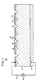
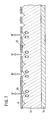
- an electron emitter 10A comprises a plate-like emitter (a substance serving as an emitter) 12 made of a dielectric material, a first electrode (e.g., an upper electrode) 14 formed on a first surface (e.g., an upper surface) of the emitter 12, a second electrode (e.g., a lower electrode) 16 formed on a second surface (e.g., a lower surface) of the emitter 12, and a pulse generation source 18 for applying a drive voltage Va between the upper electrode 14 and the lower electrode 16.
- a plate-like emitter a substance serving as an emitter
- a first electrode e.g., an upper electrode
- a second electrode e.g., a lower electrode
- a pulse generation source 18 for applying a drive voltage Va between the upper electrode 14 and the lower electrode 16.
- the upper electrode 14 has a plurality of through regions 20 where the emitter 12 is exposed.
- the emitter 12 has surface irregularities 22 due to the grain boundary of the dielectric material.
- the through regions 20 of the upper electrode 14 are formed in areas corresponding to concavities 24 due to the grain boundary of the dielectric material. In the embodiment shown in FIG. 1, one through region 20 is formed in association with one recess 24. However, one through region 20 may be formed in association with a plurality of concavities 24.
- the particle diameter of the dielectric material of the emitter 12 should preferably be in the range from 0.1 ⁇ m to 10 ⁇ m, and more preferably be in the range from 2 ⁇ m to 7 ⁇ m. In the embodiment shown in FIG. 1, the particle diameter of the dielectric material is of 3 ⁇ m.
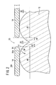
- each of the through regions 20 of the upper electrode 12 has a peripheral portion 26 having a surface 26a facing the emitter 12, the surface 26a being spaced from the emitter 12.
- a gap 28 is formed between the surface 26a, facing the emitter 12, of the peripheral portion 26 of the through region 20 and the emitter 12, and the peripheral portion 26 of the through region 20 of the upper electrode 14 is formed as an overhanging portion (flange).
- the peripheral portion 26 of the through region 20 of the upper electrode 14 is referred to as "the overhanging portion 26 of the upper electrode 14".
- convexities 30 of the surface irregularities 22 of the grain boundary of the dielectric material are shown as having a semicircular cross-sectional shape.
- the convexities 30 are not limited to the semicircular cross-sectional shape.
- the maximum distance d in the vertical direction between the surface of the convexity 30 (the inner wall surface of the concavity 24) of the grain boundary of the dielectric material and the lower surface 26a of the overhanging portion 26 of the upper electrode 14 is in the range of 0 pm ⁇ d s 10 pm.
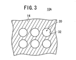
- the shape of the through region 20, particularly the shape as seen from above, as shown in FIG. 3, is the shape of a hole 32, which may be a circular shape, an elliptical shape, a track shape, a shape including a curve, or a polygonal shape such as a quadrangular shape or a triangular shape.
- the shape of the hole 32 is a circular shape.
- the hole 32 has an average diameter ranging from 0.1 pm to 10 ⁇ m.
- the average diameter represents the average of the lengths of a plurality of different line segments passing through the center of the hole 32.
- the dielectric material which the emitter 12 is made of may be a dielectric material having a relatively large dielectric constant, e.g., a dielectric constant of 1000 or larger.
- Dielectric materials of such a nature may be ceramics including barium titanate, lead zirconate, lead magnesium niobate, lead nickel niobate, lead zinc niobate, lead manganese niobate, lead magnesium tantalate, lead antimony tinate, lead titanate, lead magnesium tungstenate, lead cobalt niobate, etc.
- any of these materials a material which chiefly contains 50 weight % or more of any of these materials, or such ceramics to which there is added an oxide such as lanthanum, calcium, strontium, molybdenum, tungsten, barium, niobium, zinc, nickel, manganese, or the like, or a combination of these materials, or any of other compounds.
- nPMN-mPT nPMN-mPT
- PT lead titanate
- MPB morphotropic phase boundary
- a dielectric material may be mixed with 20 weight % of platinum.
- the emitter 12 may be in the form of a piezoelectric/electrostrictive layer or an anti-ferrodielectric layer. If the emitter 12 comprises a piezoelectric/electrostrictive layer, then it may be made of ceramics such as lead zirconate, lead magnesium niobate, lead nickel niobate, lead zinc niobate, lead manganese niobate, lead magnesium tantalate, lead nickel tantalate, lead antimony tinate, lead titanate, barium titanate, lead magnesium tungstenate, lead cobalt niobate, or the like. or a combination of any of these materials.
- ceramics such as lead zirconate, lead magnesium niobate, lead nickel niobate, lead zinc niobate, lead manganese niobate, lead magnesium tantalate, lead nickel tantalate, lead antimony tinate, lead titanate, barium titanate, lead magnesium tungstenate, lead co
- the emitter 12 may be made of chief components including 50 wt % or more of any of the above compounds. Of the above ceramics, the ceramics including lead zirconate is mostly frequently used as a constituent of the piezoelectric/electrostrictive layer of the emitter 12.
- the piezoelectric/electrostrictive layer is made of ceramics, then lanthanum, calcium, strontium, molybdenum, tungsten, barium, niobium, zinc, nickel, manganese, or the like, or a combination of these materials, or any of other compounds may be added to the ceramics.
- ceramics produced by adding SiO 2 , CeO 2 , Pb 5 Ge 3 O 11 , or a combination of any of these compounds to the above ceramics may be used.
- a material produced by adding 0.2 wt % of SiO 2 , 0.1 wt % of CeO 2 , or 1 to 2 wt % of Pb 5 Ge 3 O 11 to a PT-PZ-PMN piezoelectric material is preferable.
- the piezoelectric/electrostrictive layer should preferably be made of ceramics including as chief components lead magnesium niobate, lead zirconate, and lead titanate, and also including lanthanum and strontium.
- the piezoelectric/electrostrictive layer may be dense or porous. If the piezoelectric/electrostrictive layer is porous, then it should preferably have a porosity of 12 % or less.
- the anti-ferrodielectric layer may be made of lead zirconate as a chief component, lead zirconate and lead tin as chief components, lead zirconate with lanthanum oxide added thereto, or lead zirconate and lead tin as components with lead zirconate and lead niobate added thereto.
- the anti-ferrodielectric layer may be porous. If the anti-ferrodielectric layer is porous, then it should preferably have a porosity of 30 % or less.
- the emitter 12 is made of strontium tantalate bismuthate (SrBi 2 Ta 2 O 9 ), then its polarization inversion fatigue is small.
- Materials whose polarization inversion fatigue is small are laminar ferrodielectric compounds and expressed by the general formula of (BiO 2 ) 2+ (A m-1 B m O 3m+1 ) 2- .
- Ions of the metal A are Ca 2+ , Sr 2+ , Ba 2+ , Pb 2+ , Bi 3+ , La 3+ , etc.
- ions of the metal B are Ti 4+ , Ta 5+ , Nb 5+ , etc.
- the baking temperature can be lowered by adding glass such as lead borosilicate glass or the like or other compounds of low melting point (e.g., bismuth oxide or the like) to the piezoelectric/electrostrictive/anti-ferrodielectric ceramics.
- glass such as lead borosilicate glass or the like or other compounds of low melting point (e.g., bismuth oxide or the like) to the piezoelectric/electrostrictive/anti-ferrodielectric ceramics.
- the emitter 12 is made of piezoelectric/electrostrictive/anti-ferrodielectric ceramics, then it may be a sheet-like molded body, a sheet-like laminated body, or either one of such bodies stacked or bonded to another support substrate.
- the emitter 12 is made of a non-lead-based material, then it may be a material having a high melting point or a high evaporation temperature so as to be less liable to be damaged by the impingement of electrons or ions.
- the upper electrode 14 is made of an organic metal paste which can produce a thin film after being baked.
- a platinum resinate paste or the like should preferably be used.
- RuO 2 ruthenium oxide
- IrO 2 iridium oxide
- SrRuO 3 strontium ruthenate
- La 1-x Sr x CoO 3 e.
- the upper electrode 14 may be made of any of the above materials by any of thick-film forming processes including screen printing, spray coating, coating, dipping, electrophoresis, etc., or any of various thin-film forming processes including sputtering, an ion beam process, vacuum evaporation, ion plating, chemical vapor deposition (CVD), plating, etc.
- the upper electrode 14 is made by any of the above thick-film forming processes.
- the lower electrode 16 is made of platinum, molybdenum, tungsten, or the like.
- the lower electrode 16 is made of an electric conductor which is resistant to a high-temperature oxidizing atmosphere, e.g., a metal, an alloy, a mixture of insulative ceramics and a metal, a mixture of insulative ceramics and an alloy, or the like.
- the lower electrode 16 should be made of a precious metal having a high melting point such as platinum, iridium, palladium, rhodium, molybdenum, or the like, or a material chiefly composed of an alloy of silver and palladium, silver and platinum, platinum and palladium, or the like, or a cermet of platinum and ceramics.
- the lower electrode 16 should be made of platinum only or a material chiefly composed of a platinum-base alloy.
- the lower electrode 16 may be made of carbon or a graphite-base material. Ceramics to be added to the electrode material should preferably have a proportion ranging from 5 to 30 volume %.
- the lower electrode 16 may be made of the same material as the upper electrode, as described above.
- the lower electrode 16 should preferably be formed by any of various thick-film forming processes.
- the lower electrode 16 has a thickness of 20 ⁇ m or less or preferably a thickness of 5 ⁇ m or less.
- the assembly is heated (sintered) into an integral structure.
- the sintering process for integrally combining the emitter 12, the upper electrode 14, and the lower electrode 16 may be carried out at a temperature ranging from 500 to 1400°c, preferably from 1000 to 1400°C.
- the emitter 12 should be sintered together with its evaporation source while their atmosphere is being controlled, so that the composition of the emitter 12 will not become unstable at high temperatures.
- the film which will serve as the upper electrode 14 is shrunk from the thickness of 10 pm to the thickness of 0.1 ⁇ m, and simultaneously a plurality of holes are formed therein.
- a plurality of through regions 20 are formed in the upper electrode 14, and the peripheral portions 26 of the through regions 20 are turned into overhanging portions.
- the film which will serve as the upper electrode 14 may be patterned by etching (wet etching or dry etching) or lift-off, and then may be sintered. In this case, recesses or slits may easily be formed as the through regions 20.
- the emitter 12 may be covered with a suitable member, and then sintered such that the surface of the emitter 12 will not be exposed directly to the sintering atmosphere.
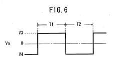
- a drive voltage Va is applied between the upper electrode 14 and the lower electrode 16.
- the drive voltage Va is defined as a voltage, such as a pulse voltage or an alternating-current voltage, which abruptly changes, with time, from a voltage level higher or lower than a reference voltage (e.g., 0 V) to a voltage level that is lower or higher than the reference voltage.
- a reference voltage e.g. 0 V
- a triple junction is formed in a region of contact between the upper surface of the emitter 12, the upper electrode 14, and a medium (e.g., a vacuum) around the electron emitter 10A.
- the triple junction is defined as an electric field concentration region formed by a contact between the upper electrode 14, the emitter 12, and the vacuum.
- the triple junction includes a triple point where the upper electrode 14, the emitter 12, and the vacuum exist as one point.
- the vacuum level in the atmosphere should preferably in the range from 10 2 to 10 -6 Pa and more preferably in the range from 10 -3 to 10 -5 Pa.
- the triple junction is formed on the overhanging portion 26 of the upper electrode 14 and the peripheral area of the upper electrode 14. Therefore, when the drive voltage Va is applied between the upper electrode 14 and the lower electrode 16, an electric field concentration occurs at the triple junction.
- a first electron emission process will first be described below with reference to FIGS. 4 and 5.
- a voltage V2 lower than a reference voltage e.g., 0 V
- a voltage V1 higher than the reference voltage is applied to the lower electrode 16.
- an electric field concentration occurs at the triple junction, accumulating electrons in the portions of the emitter 12 which are exposed through the through regions 20 of the upper electrode 14 and regions near the peripheral portion of the upper electrode 14.
- the upper electrode 14 functions as an electron supply source.
- a reverse electric field concentration occurs at the triple junction referred to above, causing the portions of the emitter 12 where electrons have been accumulated to emit electrons through the through regions 20. Electrons are also emitted from the portions of the emitter 12 near the outer peripheral portion of the upper electrode 14.
- a second electron emission process will be described below.
- a voltage V3 higher than a reference voltage is applied to the upper electrode 14, and a voltage V4 lower than the reference voltage is applied to the lower electrode 16.
- the electron emitter is prepared for electron emission (e.g., the emitter 12 is polarized in one direction).
- the voltage level of a drive voltage Va is quickly changed, i.e., the voltage V4 lower than the reference voltage is applied to the upper electrode 14, and the voltage V3 higher than the reference voltage is applied to the lower electrode 16.
- an electric field concentration occurs at the triple junction referred to above, causing the upper electrode 14 to emit primary electrons, which impinge upon the portions of the emitter 12 which are exposed through the through region 20 and the regions near the outer peripheral portion of the upper electrode 14.
- secondary electrons including reflected primary electrons
- secondary electrons are emitted from the portions hit by the primary electrons.
- secondary electrons are emitted from the through region 20 and the regions near the outer peripheral portion of the upper electrode 14 in an initial stage of the second output period T2.
- the upper electrode 14 since the upper electrode 14 has the plural through regions 20, electrons are uniformly emitted from each of the through regions 20 and the outer peripheral portions of the upper electrode 14. Thus, any variations in the overall electron emission characteristics of the electron emitter 12 are reduced, making it possible to facilitate the control of the electron emission and increase the electron emission efficiency.
- the gap 28 is formed between the overhanging portion 26 of the upper electrode 14 and the emitter 12, when the drive voltage Va is applied, an electric field concentration tends to be produced in the region of the gap 24. This leads to a higher efficiency of the electron emission, making the drive voltage lower (emitting electrons at a lower voltage level).
- the upper electrode 12 has the overhanging portion 26 on the peripheral portion of the through region 20, together with the increased electric field concentration in the region of the gap 28, electrons are easily emitted from the overhanging portion 26 of the upper electrode 14. This leads to a larger output and higher efficiency of the electron emission, making the drive voltage lower.
- the overhanging portion 16 of the upper electrode 14 functions as a gate electrode (a control electrode, a focusing electronic lens, or the like)
- the straightness of emitted electrons can be increased. This is effective in reducing crosstalk if a number of electron emitters 10A are arrayed for use as an electron source of a display.
- the electron emitter 10A according to the first embodiment is capable of easily developing a high electric field concentration, provides many electron emission regions, has a larger output and higher efficiency of the electron emission, and can be driven at a lower voltage (lower power consumption).
- the upper surface of the emitter 12 has the surface irregularities 22 due to the grain boundary of the dielectric material.
- the upper electrode 12 has the through regions 20 in portions corresponding to the concavities 24 of the grain boundary of the dielectric material, the overhanging portions 26 of the upper electrode 14 can easily be realized.
- the maximum angle ⁇ between the upper surface of the emitter 12, i.e., the surface of the convexity 30 (which is also the inner wall surface of the concavity 24) of the grain boundary of the dielectric material, and the lower surface 26a of the overhanging portion 26 of the upper electrode 14 is in the range of 1° ⁇ ⁇ ⁇ 60°.
- the maximum distance d in the vertical direction between the surface of the convexity 30 (the inner wall surface of the concavity 24) of the grain boundary of the dielectric material and the lower surface 26a of the overhanging portion 26 of the upper electrode 14 is in the range of 0 ⁇ m ⁇ d ⁇ 10 ⁇ m.
- the through region 20 is in the shape of the hole 32.
- the portions of the emitter 12 where the polarization is inverted or changed depending on the drive voltage Va applied between the upper electrode 14 and the lower electrode 16 include a portion (first portion) 40 directly below the upper electrode 14 and a portion (second portion) 42 corresponding to a region extending from the inner peripheral edge of the through region 20 inwardly of the through region 20.
- the second portion 42 changes depending on the level of the drive voltage Va and the degree of the electric field concentration.
- the average diameter of the hole 32 is in the range from 0.1 pm to 10 ⁇ m. Insofar as the average diameter of the hole 32 is in this range, the distribution of electrons emitted through the through region 20 is almost free of any variations, allowing electrons to be emitted efficiently.
- the average diameter of the hole 32 is less than 0.1 ⁇ m, then the region where electrons are accumulated is made narrower, reducing the amount of emitted electrons. While one solution would be to form many holes 32, it would be difficult and highly costly to form many holes 32. If the average diameter of the hole 32 is in excess of 10 ⁇ m, then the proportion (share) of the portion (second portion) 42 which contributes to the emission of electrons in the portion of the emitter 12 that is exposed through the through region 20 is reduced, resulting in a reduction in the electron emission efficiency.
- the overhanging portion 26 of the upper electrode 14 may have upper and lower surfaces extending horizontally as shown in FIG. 2.
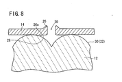
- the overhanging portion 26 may have a lower surface 26a extending substantially horizontally and an upper end raised upwardly.
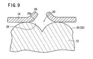
- the overhanging portion 26 may have a lower surface 26a inclined progressively upwardly toward the center of the through region 20.
- the overhanging portion 26 may have a lower surface 26a inclined progressively downwardly toward the center of the through region 20.
- the arrangement shown in FIG. 8 is capable of increasing the function as a gate electrode.
- the arrangement shown in FIG. 10 makes it easier to produce a higher electric field concentration for a larger output and higher efficiency of the electron emission because the gap 28 is narrower.
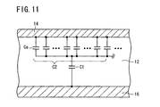
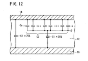
- the electron emitter has in its electrical operation a capacitor C1 due to the emitter 12 and a cluster of capacitors Ca due to respective gaps 28, disposed between the upper electrode 14 and the lower electrode 16.
- the capacitors Ca due to the respective gaps 28 are connected parallel to each other into a single capacitor C2.
- the capacitor C1 due to the emitter 12 is connected in series to the capacitor C2 which comprises the cluster of capacitors Ca.
- the capacitor C1 due to the emitter 12 is not directly connected in series to the capacitor C2 which comprises the cluster of capacitors Ca, but the capacitive component that is connected in series varies depending on the number of the through regions 20 formed in the upper electrode 14 and the overall area of the through regions 20.
- the capacitor C2 which comprises the cluster of capacitors Ca has a capacitance of 0.885 pF, and the capacitor C1 due to the emitter 12 has a capacitance of 35.4 pF. If the portion of the capacitor C1 due to the emitter 12 which is connected in series to the capacitor C2 which comprises the cluster of capacitors Ca is 25 % of the entire capacitor C1, then that series-connected portion has a capacitance (including the capacitance of capacitor C2 which comprises the cluster of capacitors Ca) of 0.805 pF, and the remaining portion has a capacitance of 26.6 pF.
- the overall capacitance is 27.5 pF. This capacitance is 78 % of the capacitance 35.4 pF of the capacitor C1 due to the emitter 12. Therefore, the overall capacitance is smaller than the capacitance of the capacitor C1 due to the emitter 12.
- the capacitance of the cluster of capacitors Ca due to the gaps 28 is relatively small. Because of the voltage division between the cluster of capacitors Ca and the capacitor C1 due to the emitter 12, almost the entire applied voltage Va is applied across the gaps 28, which are effective to produce a larger output of the electron emission.
- the capacitor C2 which comprises the cluster of capacitors Ca is connected in series to the capacitor C1 due to the emitter 12, the overall capacitance is smaller than the capacitance of the capacitor C1 due to the emitter 12. This is effective to provide such preferred characteristics that the electron emission is performed for a larger output and the overall power consumption is lower.
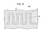
- an electron emitter 10Aa differs from the above electron emitter 10A in that the through region 20 has a shape, particularly a shape viewed from above, in the form of a recess 44.
- the recess 44 should preferably be shaped such that a number of recesses 44 are successively formed into a comb-toothed recess 46.
- the comb-toothed recess 46 is effective to reduce variations in the distribution of electrons emitted through the through region 20 for efficient electron emission.
- the average width represents the average of the lengths of a plurality of different line segments extending perpendicularly across the central line of the recess 44.
- an electron emitter 10Ab according to a second modification differs from the above electron emitter 10A in that the through region 20 has a shape, particularly a shape viewed from above, in the form of a slit 48.
- the slit 48 is defined as something having a major axis (extending in a longitudinal direction) whose length is 10 times or more the length of the minor axis (extending in a transverse direction) thereof. Those having a major axis (extending in a longitudinal direction) whose length is less than 10 times the length of the minor axis (extending in a transverse direction) thereof are defined as holes 32 (see FIG. 3).
- the slit 48 includes a succession of holes 32 in communication with each other.
- the slit 48 should preferably have an average width ranging from 0.1 ⁇ m to 10 pm for reducing variations in the distribution of electrons emitted through the through region 46 for efficient electron emission.
- the average width represents the average of the lengths of a plurality of different line segments extending perpendicularly across the central line of the slit 48.
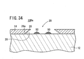
- an electron emitter 10Ac differs from the above electron emitter 10A in that a floating electrode 50 exists on the portion of the upper surface of the emitter 12 which corresponds to the through region 20, e.g., in the concavity 24 due to the grain boundary of the dielectric material.
- the floating electrode 50 also serves as an electron supply source, a number of electrons can be emitted out through the through region 20 in the second output period T2 (see FIG. 4) according to the first electron emission process described above) in an electron emission stage.
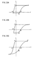
- the characteristics of the electron emitter 10A according to the first embodiment particularly, the voltage vs. charge quantity characteristics (voltage vs. polarized quantity characteristics), will be described below.
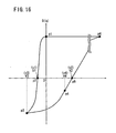
- a region of the emitter 12 from which electrons are emitted is defined as an electron emission region, then at a point p1 (initial state) where the reference voltage is applied, almost no electrons are stored in the electron emission region. Thereafter, when a negative voltage is applied, the amount of positive charges in the electron emission region increases, storing electrons.
- the level of the negative voltage increases in a negative direction, electrons are progressively stored in the electron emission region until the amount of positive charges and the amount of electrons are held in equilibrium with each other at a point p2 of the negative voltage.
- the level of the negative voltage further increases in the negative direction, the stored amount of electrons increases, making the amount of negative charges greater than the amount of positive charges.
- the accumulation of electrons is saturated at a point P3.
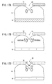
- FIG. 16 The characteristics shown in FIG. 16 will be described below in terms of the voltage vs. charge quantity characteristics. It is assumed, in the description which follows, that the emitter 12 is polarized in one direction, with dipoles having negative poles facing toward the upper surface of the emitter 12 (see FIG. 17A).
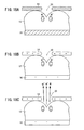
- the polarization starts being inverted substantially at the time the negative voltage exceeds a negative coercive voltage (see the point p2 in FIG. 16). All the polarization is inverted at the point p3 shown in FIG. 16 (see FIG. 17B). Because of the polarization inversion, an electric field concentration occurs at the triple junction, causing electrons to be accumulated in the portion of the emitter 12 which is exposed through the through region 20 of the upper electrode 14 and the portion of the emitter 12 which is near the peripheral portion of the upper electrode 14 (see FIG. 17C). In particular, electrons are emitted (emitted inwardly) from the upper electrode 14 toward the portion of the emitter 12 which is exposed through the through region 20 of the upper electrode 14. At the point p3 shown in FIG. 16, the accumulation of electrons is saturated.
- the upper surface of the emitter 12 is kept charged up to a certain voltage level (see FIG. 18A).
- the level of the positive voltage is increased, there is produced a region where the negative poles of dipole moments start facing the upper surface of the emitter 12 (see FIG. 18B) immediately prior to the point p4 in FIG. 16.
- the level is further increased, electrons start being emitted after the point p4 in FIG. 16 (see FIG. 18C).
- the positive voltage is increased in the positive direction, the amount of emitted electrons is increased.
- the characteristics of the electron emitter 10A has have the following features:
- the electron emitter 10A according to the first embodiment has the above characteristics, it can easily be applied to a display having a plurality of electron emitters 10A arrayed in association with respective pixels for emitting electrons from the electron emitters 10A to display an image.
- a display 100 using electron emitters 10A according to the first embodiment will be described below.
- the display 100 has a display unit 101 comprising a matrix or staggered pattern of electron emitters 10A corresponding to respective pixels, and a drive circuit 104 for driving the display unit 101.
- One electron emitter 10A may be assigned to each pixel, or a plurality of electron emitters 10A may be assigned to each pixel. In the present embodiment, it is assumed for the sake of brevity that one electron emitter 10A is assigned to each pixel.
- the drive circuit 104 has a plurality of row select lines 106 for selecting rows in the display unit 102 and a plurality of signal lines 108 for supplying pixel signals Sd to the display unit 102.
- the drive circuit 104 also has a row selecting circuit 110 for supplying a selection signal Ss selectively to the row select lines 106 to successively select a row of electron emitters 10A, a signal supplying circuit 112 for outputting parallel pixel signals Sd to the signal lines 108 to supply the pixel signals Sd to a row (selected row) selected by the row selecting circuit 110, and a signal control circuit 114 for controlling the row selecting circuit 110 and the signal supplying circuit 112 based on a video signal Sv and a synchronizing signal Sc that are input to the signal control circuit 114.
- a power supply circuit 116 (which supplies 50 V and 0 V, for example) is connected to the row selecting circuit 110 and the signal supplying circuit 112.
- a pulse power supply 118 is connected between a negative line between the row selecting circuit 110 and the power supply circuit 116, and GND (ground).
- the pulse power supply 118 outputs a pulsed voltage waveform having a reference voltage (e.g., 0 V) during a charge accumulation period Td, to be described later, and a certain voltage (e.g., - 400 V) during a light emission period Th.
- the row selecting circuit 110 outputs the selection signal Ss to the selected row and outputs a non-selection signal Sn to the unselected rows.
- the row selecting circuit 110 outputs a constant voltage (e.g., - 350 V) which is the sum of a power supply voltage (e.g., 50 V) from the power supply circuit 116 and a voltage (e.g., - 400 V) from the pulse power supply 118.
- the signal supplying circuit 112 has a pulse generating circuit 120 and an amplitude modulating circuit 122.
- the pulse generating circuit 120 generates a pulse signal Sp having a constant pulse period and a constant amplitude (e.g., 50 V) during the charge accumulation period Td, and outputs a reference voltage (e.g., 0 V) during the light emission period Th.
- the amplitude modulating circuit 122 amplitude-modulates the pulse signal Sp from the pulse generating circuit 120 depending on the luminance levels of the pixels of the selected row, and outputs the amplitude-modulated pulse signal Sp as the pixel signal for the pixels Sd of the selected row.
- the amplitude modulating circuit 122 outputs the reference voltage from the pulse generating circuit 120 as it is.
- the timing control in the amplitude modulating circuit 122 and the supply of the luminance levels of the selected pixels to the amplitude modulating circuit 122 are performed by the signal control circuit 114.
- the amplitude of the pulse signal Sp is set to a low level Vsl (see FIG. 20A)
- the amplitude of the pulse signal Sp is set to a medium level Vsm (see FIG. 20B)
- the amplitude of the pulse signal Sp is set to a high level Vsh (see FIG. 20C).
- the amplitude of the pulse signal Sp is modulated into three levels in the above examples, if the amplitude modulation is applied to the display 100, then the pulse signal Sp is amplitude-modulated to 128 levels or 256 levels depending on the luminance levels of the pixels.
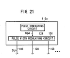
- a modified signal supplying circuit 112a has a pulse generating circuit 124 and a pulse width modulating circuit 126.
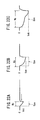
- the pulse generating circuit 124 generates and outputs a pulse signal Spa (indicated by the broken lines in FIGS. 22A through 22C) where the positive-going edge of a voltage waveform (indicated by the solid lines in FIGS. 22A through 22C) applied to the electron emitter 10A is continuously changed in level, during the charge accumulation period Td.
- the pulse generating circuit 124 outputs a reference voltage during the light emission period Th.
- the pulse width modulating circuit 126 modulates the pulse width Wp (see FIGS.
- the pulse width modulating circuit 126 outputs the reference voltage from the pulse generating circuit 124 as it is.
- the timing control in the pulse width modulating circuit 126 and the supply of the luminance levels of the selected pixels to the pulse with modulating circuit 126 are also performed by the signal control circuit 114.
- the pulse width p of the pulse signal Sp is set to a short width, setting the substantial amplitude to a low level Vsl (see FIG. 22A)
- the pulse width Wp of the pulse signal Sp is set to a medium width, setting the substantial amplitude to a medium level Vsm (see FIG. 22B)
- the pulse width Wp of the pulse signal Sp is set to a long width, setting the substantial amplitude to a high level Vsh (see FIG. 22C).
- the pulse width Wp of the pulse signal Sp is modulated into three levels in the above examples, if the amplitude modulation is applied to the display 100, then the pulse signal Sp is pulse-width-modulated to 128 levels or 256 levels depending on the luminance levels of the pixels.
- the voltage level at the point p4 where electrons start being emitted is substantially the same. That is, even if the applied voltage changes to the voltage level indicated at the point p4 after electrons are accumulated, the amount of accumulated electrons does not change essentially. It can thus be seen that a memory effect has been caused.
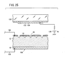
- a transparent plate 130 made of glass or acrylic resin is placed above the upper electrode 14, and a collector electrode 132 in the form of a transparent electrode, for example, is placed on the reverse side of the transparent plate 130 (which faces the upper electrode 14), the collector electrode 132 being coated with a phosphor 134.
- a bias voltage source 136 (collector voltage Vc) is connected to the collector electrode 32 through a resistor.
- the electron emitter 10A is naturally placed in a vacuum.
- the vacuum level in the atmosphere should preferably in the range from 10 2 to 10 -6 Pa and more preferably in the range from 10 -3 to 10 -5 Pa.
- the collector electrode 132 is formed on the reverse side of the transparent plate 130, and the phosphor 134 is formed on the surface of the collector electrode 132 (which faces the upper electrode 14).
- the phosphor 134 may be formed on the reverse side of the transparent plate 130, and the collector electrode 132 may be formed in covering relation to the phosphor 134.
- Such another arrangement is for use in a CRT or the like where the collector electrode 132 functions as a metal back. Electrons emitted from the emitter 12 pass through the collector electrode 132 into the phosphor 134, exciting the phosphor 134. Therefore, the collector electrode 132 is of a thickness which allows electrons to pass therethrough, preferably be 100 nm or less thick. As the kinetic energy of the emitted electrons is larger, the thickness of the collector electrode 132 may be increased.
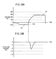
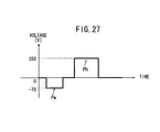
- the emission of electrons from the electron emitter 10A was observed. Specifically, as shown in FIG. 26A, a write pulse Pw having a voltage of - 70 V was applied to the electron emitter 10A to cause the electron emitter 10A to accumulate electrons, and thereafter a turn-on pulse Ph having a voltage of 280 V was applied to cause the electron emitter 10A to emit electrons.
- the emission of electrons was measured by detecting the light emission from the phosphor 134 with a light-detecting device (photodiode). The detected waveform is shown in FIG. 26B.
- the write pulse Pw and the turn-on pulse Ph had a duty cycle of 50 %.
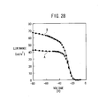
- the solid-line curve A represents the characteristics at the time the turn-on pulse Ph had an amplitude of 200 V and the write pulse Pw had an amplitude changing from - 10 V to - 80 V
- the solid-line curve B represents the characteristics at the time the turn-on pulse Ph had an amplitude of 350 V and the write pulse Pw had an amplitude changing from - 10 V to - 80 V.
- the write pulse Pw when the write pulse Pw is changed from - 20 V to - 40 V, it can be understood that the light emission luminance changes substantially linearly.
- a comparison between the amplitudes 350 V and 200 V of the turn-on pulse Ph in particular indicates that a change in the light emission luminance in response to the write pulse Pw at the time the amplitude of the turn-on pulse Ph is 350 V has a wider dynamic range, which is advantageous for increased luminance and contrast for the display of images. This tendency appears to be more advantageous as the amplitude of the turn-on pulse Ph increases in a range until the light emission luminance is saturated with respect to the setting of the amplitude of the turn-on pulse Ph. It is preferable to set the amplitude of the turn-on pulse Ph to an optimum value in relation to the withstand voltage and power consumption of the signal transmission system.
- the solid-line curve C represents the characteristics at the time the write pulse Pw had an amplitude of - 40 V and the turn-on pulse Ph had an amplitude changing from 50 V to 400 V
- the solid-line curve D represents the characteristics at the time the write pulse Pw had an amplitude of - 70 V and the turn-on pulse Ph had an amplitude changing from 50 V to 400 V.
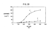
- the solid-line curve E represents the characteristics at the time the level of the collector voltage Vc was 3 kV and the amplitude of the turn-on pulse Ph was changed from 80 V to 500 V
- the solid-line curve F represents the characteristics at the time the level of the collector voltage Vc was 7 kV and the amplitude of the turn-on pulse Ph was changed from 80 V to 500 V.
- a change in the light emission luminance in response to the turn-on pulse Ph has a wider dynamic range when the collector voltage Vc is 7 kV than when the collector voltage Vc is 3 kV, which is advantageous for increased luminance and contrast for the display of images. This tendency appears to be more advantageous as the level of the collector voltage Vc increases. It is preferable also in this case to set the level of the collector voltage Vc to an optimum value in relation to the withstand voltage and power consumption of the signal transmission system.
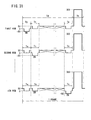
- FIG. 31 shows operation of pixels in the first row and the first column, the second row and the first column, and the nth row and the first column.
- the electron emitter 10A used in the first drive method has such characteristics that the coercive voltage v1 at the point p2 shown in FIG. 16 is - 20 V, for example, the coercive voltage v2 at the point p5 is + 70 V, the voltage v3 at the point p3 is - 50 V, and the voltage v4 at the point p4 is + 50 V.
- each selection period Ts becomes a selection period Ts for a corresponding row, it becomes a non-selection period Tn for non-corresponding n-1 rows.
- all the electron emitters 10A are scanned in the charge accumulation period Td, and voltages depending on the luminance levels of corresponding pixels are applied to a plurality of electron emitters 10A which correspond to pixels to be turned on (to emit light), thereby accumulating charges (electrons) in amounts depending on the luminance levels of the corresponding pixels in the electron emitters 12 which correspond to the pixels to be turned on.
- a constant voltage is applied to all the electron emitters 10A to cause the electron emitters 10A which correspond to the pixels to be turned on to emit electrons in amounts depending on the luminance levels of the corresponding pixels, thereby emitting light from the pixels to be turned on.
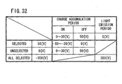
- a selection signal Ss of 50 V for example, is supplied to the row selection line 106 of the first row, and a non-selection signal Sn of 0 V, for example, is applied to the row selection lines 106 of the other rows.
- a pixel signal Sd supplied to the signal lines 108 of the pixels to be turned on (to emit light) of all the pixels of the first row has a voltage in the range from 0 V to 30 V, depending on the luminance levels of the corresponding pixels. If the luminance level is maximum, then the voltage of the pixel signal Sd is 0 V.
- the pixel signal Sd is modulated depending on the luminance level by the amplitude modulating circuit 122 shown in FIG. 19 or the pulse width modulating circuit 126 shown in FIG. 21.
- each electron emitter 10A accumulates electrons depending on the applied voltage.
- the electron emitter 12 corresponding to the pixel in the first row and the first column is in a state at the point p3 shown in FIG. 16 as the luminance level of the pixel is maximum, and the portion of the emitter 12 which is exposed through the through region 20 of the upper electrode 14 accumulates a maximum amount of electrons.
- a pixel signal Sd supplied to the electron emitters 10A which correspond to pixels to be turned off (to extinguish light) has a voltage of 50 V, for example. Therefore, a voltage of 0 V is applied to the electron emitters 10A which correspond to pixels to be turned off, bringing those electron emitters 10A into a state at the point p1 shown in FIG. 16, so that no electrons are accumulated in those electron emitters 10A.
- a selection signal Ss of 50 V is supplied to the row selection line 106 of the second row, and a non-selection signal Sn of 0 V is applied to the row selection lines 106 of the other rows.
- a voltage ranging from - 50 V to - 20 V depending on the luminance level is also applied between the upper and lower electrodes 14, 16 of the electron emitter 10A which corresponds to each of the pixels to be turned on.
- a voltage ranging from 0 V to 50 V is applied between the upper and lower electrodes 14, 16 of the electron emitter 10A which corresponds to each of unselected pixels in the first row, for example.
- this voltage is of a level not reaching the point 4 in FIG. 16, no electrons are emitted from the electron emitters 10A which correspond to the pixels to be turned on in the first row. That is, the unselected pixels in the first row are not affected by the pixel signal that is supplied to the selected pixels in the second row.
- a selection signal Ss of 50 V is supplied to the row selection line 106 of the nth row, and a non-selection signal Sn of 0 V is applied to the row selection lines 106 of the other rows.
- a voltage ranging from - 50 V to - 20 V depending on the luminance level is also applied between the upper and lower electrodes 14, 16 of the electron emitter 10A which corresponds to each of the pixels to be turned on.
- a voltage ranging from 0 V to 50 V is applied between the upper and lower electrodes 14, 16 of the electron emitter 10A which corresponds to each of unselected pixels in the first through (n-1)th rows.
- no electrons are emitted from the electron emitters 10A which correspond to the pixels to be turned on, of those unselected pixels.
- a reference voltage (e.g., 0 V) is applied from the signal supplying circuit 112 to the upper electrodes 14 of all the electron emitters 10A, and a voltage of - 350 V (the sum of the voltage of - 400 V from the pulse power supply 118 and the power supply voltage 50 V from the row selecting circuit 110) is applied to the lower electrodes 16 of all the electron emitters 10A.
- a high voltage (+ 350 V) is applied between the upper and lower electrodes 14, 16 of all the electron emitters 10A.
- All the electron emitters 10A are now brought into a state at the point p6 shown in FIG. 16.
- FIG. 18C electrons are emitted from the portion of the emitter 12 where the electrons have been accumulated, through the through region 20. Electrons are also emitted from near the outer peripheral portion of the upper electrode 14.
- Electrons are thus emitted from the electron emitters 10A which correspond to the pixels to be turned on, and the emitted electrons are led to the collector electrodes 132 which correspond to those electron emitters 10A, exciting the corresponding phosphors 134 which emit light. In this manner, an image is displayed on the surface of the transparent plate 130.
- the electron emitter according to the first embodiment can easily be applied to the display 100 which has a plurality of electron emitters 10A arrayed in association with respective pixels for emitting electrons from the electron emitters 10A to display an image.
- the electron emitters 10A are scanned, and voltages depending on the luminance levels of corresponding pixels are applied to a plurality of electron emitters 10A which correspond to pixels to be turned on, thereby accumulating charges in amounts depending on the luminance levels of the corresponding pixels in the electron emitters 10A which correspond to the pixels to be turned on.
- a constant voltage is applied to all the electron emitters 10A to cause the electron emitters 10A which correspond to the pixels to be turned on to emit electrons in amounts depending on the luminance levels of the corresponding pixels, thereby emitting light from the pixels to be turned on.
- the voltage V3 at which the accumulation of electrons is saturated and the voltage V4 at which electrons start being emitted are related to each other by 1 ⁇
- the electron emitters 10A are arranged in a matrix and selected row by row in synchronism with the horizontal scanning period, and pixel signals Sd depending on the luminance levels of pixels are supplied to the selected electron emitters 10A, the pixel signals Sd are also supplied to unselected pixels.
- the unselected electron emitters 10A are affected by the pixel signals Sd and emit electrons, then problems arise in that the quality of displayed images is degraded and the contrast thereof is lowered.
- the voltage levels of the pixel signals Sd supplied to selected electron emitters 10A are set to desired voltages in the range from the reference voltage to the voltage V3 and signals that are of opposite polarity to the pixel signals Sd, for example, are supplied to unselected electron emitters 10A, the unselected pixels are not affected by the pixel signals Sd supplied to the selected pixels, and a memory effect is achieved at each pixel for higher luminance and higher contrast.
- pixels are made up of electron emitters 10A
- a high voltage needs to be applied to the electron emitters 10A to emit light from the pixels. Therefore, for accumulating charges in the pixels and emitting light from the pixels when the pixels are scanned, a high voltage needs to be applied to the pixels during a period (e.g., one frame) for displaying one image, resulting in the problem of increased electric power consumption.
- Circuits for selecting electron emitters 10A and supplying the pixel signals Sd to the selected electron emitters 10A need to be able to handle the high voltage.
- a voltage is applied to all the electron emitters 10A, emitting light from the pixels which correspond to the electron emitters 10A to be turned on.
- the period Th during which a voltage (emission voltage) for emitting electrons is applied to all the electron emitters 10A is necessarily shorter than one frame.
- the period during which to apply the emission voltage can be reduced, the power consumption can be made much smaller than if charges are accumulated and light is emitted when the pixels are scanned.
- the circuit for applying voltages depending on luminance levels to the electron emitters 10A can be driven at a low voltage.
- the pixel signal depending on an image and the selection signal Ss/non-selection signal Sn in the charge accumulation period Td need to be applied for each row or each column.
- the drive voltage may be of a few tens of volts
- an inexpensive multi-output driver for use with fluorescent display tubes may be used.
- a voltage for emitting sufficient electrons is likely to be higher than the drive voltage. Since all the pixels to be turned on may be driven altogether, no multi-output circuit component is required.
- a one-output drive circuit in the form of a discrete component having a high withstand voltage may be sufficient. Therefore, the drive circuit may be inexpensive and may be small in circuit scale.
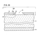
- An electron emitter 10B according to a second embodiment will be described below with reference to FIG. 33.
- the electron emitter 10B according to the second embodiment is of an arrangement that is essentially the same as the electron emitter 10A according to the first embodiment, but is characterized in that the upper electrode 14 has a thickness t greater than 40 ⁇ m, and the through region 20 is artificially formed by etching (wet etching or dry etching), liftoff, laser, etc.
- the through region 20 may be shaped as the hole 32, the recess 44, or the slit 48.
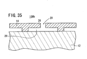
- the lower surface 26a of the peripheral portion 26 of the through region 2 in the upper electrode 14 is inclined progressively upwardly toward the center of the through region 20.
- This shape may simply be formed by liftoff, for example.
- the electron emitter 10B according to the second embodiment is capable of easily producing a high electric field concentration as with the electron emitter 10A according to the first embodiment.
- the electron emitter 10B according to the second embodiment is also capable of providing many electron emission regions for a larger output and higher efficiency of the electron emission, and can be driven at a lower voltage (lower power consumption).
- floating electrodes 50 may be present on a region of the upper surface of the emitter 12 which corresponds to the through region 20.
- an electrode having a substantially T-shaped cross-sectional shape may be formed as the upper electrode 14.
- the upper electrode 14, particularly, the peripheral portion 26 of the through region 20 of the upper electrode 14, may be raised.
- This configuration may be achieved by including a material which will be gasified in the sintering process in the film material of the upper electrode 14. In the sintering process, the material is gasified, forming a number of through regions 20 in the upper electrode 14 with the peripheral portions 26 of the through regions 20 being raised.
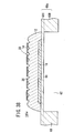
- An electron emitter 10C according to a third embodiment will be described below with reference to FIG. 37.
- the electron emitter 10C is of an arrangement that is essentially the same as the electron emitter 10A according to the first embodiment, but differs therefrom in that it has one board 60 made of ceramics, a lower electrode 16 formed on the board 60, an emitter 12 formed on the board 60 in covering relation to the lower electrode 16, and an upper electrode 14 formed on the emitter 12.
- the board 60 has a cavity 62 defined in the position corresponding to each emitter 12 and serving part of a thin-wall portion.
- the cavity 62 communicates with the exterior via a small-diameter through hole 64 which is defined in the opposite end surface of the board 60.
- the board 60 includes a thin-wall portion lying over the cavity 62 (hereinafter referred to as "thin-wall portion 66") and a thick-wall portion other than the thin-wall portion, which functions as a stationary block 68 supporting the thin-wall portion 66.
- the board 60 thus constructed may be regarded as a unitary laminated structural body having a lowermost board layer 60A, an intermediate spacer layer 60B, and an uppermost thin layer 60C, with the cavity 62 defined in the spacer layer 60B in alignment with the emitter 12.
- the board layer 60A functions as both a stiffening board and a wiring board.
- the board 60 may be of an integrally sintered structure made up of the board layer 60A, the spacer layer 60B, and the thin layer 60C, or may be formed by bonding these layers 60A through 60C.
- the thin-wall portion 66 should preferably be made of a highly heat-resistant material for the reason that the thin-wall portion 66 is not modified when at least the emitter 12 is formed if the thin-wall portion 66 is directly supported by the stationary block 68 without using a material of poor heat resistance such as an organic adhesive or the like.
- the thin-wall portion 66 should preferably be made of an electrically insulating material in order to provide an electric isolation between an interconnection leading to the upper electrode 14 on the board 60 and an interconnection leading to the lower electrode 16.
- the thin-wall portion 66 may be made of a highly heat-resistant metal or a material such as an enameled material where a surface of such a highly heat-resistant metal is covered with a ceramic material such as glass or the like.
- ceramics is optimum as the material of the thin-wall portion 66.
- the ceramics of the thin-wall portion 66 may be stabilized zirconium oxide, aluminum oxide, magnesium oxide, titanium oxide, spinel, mullite, aluminum nitride, silicon nitride, glass, or a mixture thereof.
- aluminum oxide and stabilized zirconium oxide are preferable from the standpoint of strength and rigidity.
- Stabilized zirconium oxide is particularly preferable because it provides relatively high mechanical strength and relatively high tenacity and causes relatively weak chemical reactions with the upper electrode 14 and the lower electrode 16.
- Stabilized zirconium oxide includes both stabilized zirconium oxide and partially stabilized zirconium oxide. Stabilized zirconium oxide does not cause a phase transition because it has a crystalline structure such as a cubic structure or the like.
- Zirconium oxide causes a phase transition in a monoclinic structure and a tetragonal structure at about 1000°C, and may crack upon such a phase transition.
- Stabilized zirconium oxide contains 1 - 30 mol % of a stabilizer such as calcium oxide, magnesium oxide, yttrium oxide, scandium oxide, ytterbium oxide, cerium oxide, or an oxide of a rare earth metal.
- the stabilizer should preferably contain ytterbium oxide in order to increase the mechanical strength of the board 60.
- the stabilizer should preferably contain 1.5 to 6 mol % of yttrium oxide, or more preferably 2 to 4 mol % of yttrium oxide, and furthermore should preferably contain 0.1 to 5 mol % of aluminum oxide.
- the crystalline phase may be a mixture of cubic and monoclinic systems, a mixture of tetragonal and monoclinic systems, or a mixture of cubic, tetragonal and monoclinic systems. Particularly, a mixture of cubic and monoclinic systems or a mixture of tetragonal and monoclinic systems is most preferable from the standpoint of strength, tenacity, and durability.
- the board 60 is made of ceramics, then it is constructed of many crystal grains.
- the average diameter of the crystal grains should preferably be in the range from 0.05 to 2 ⁇ m and more preferably in the range from 0.1 to 1 ⁇ m.
- the stationary block 68 should preferably be made of ceramics.
- the stationary block 68 may be made of ceramics which is the same as or different from the ceramics of the thin-wall portion 66.
- the ceramics of the stationary block 68 may be stabilized zirconium oxide, aluminum oxide, magnesium oxide, titanium oxide, spinel, mullite, aluminum nitride, silicon nitride, glass, or a mixture thereof.
- the board 60 used in the electron emitter 10C is made of a material containing zirconium oxide as a chief component, a material containing aluminum oxide as a chief component, or a material containing a mixture of zirconium oxide and aluminum oxide as a chief component. Particularly preferable is a material chiefly containing zirconium oxide.
- Clay or the like may be added as a sintering additive.
- Components of such a sintering additive need to be adjusted so that the sintering additive does not contain excessive amounts of materials which can easily be vitrified, e.g., silicon oxide, boron oxide, etc. This is because while these easily vitrifiable materials are advantageous in joining the board 60 to the emitter 12, they promote a reaction between the board 60 and the emitter 12, making it difficult to keep the desired composition of the emitter 12 and resulting in a reduction in the device characteristics.
- the easily vitrifiable materials such as silicon oxide in the board 60 should preferably be limited to 3 % by weight or less or more preferably to 1 % by weight or less.
- the chief component referred to above is a component which occurs at 50 % by weight or more.
- the thickness of the thin-wall portion 66 and the thickness of the emitter 12 should preferably be of substantially the same level. If the thickness of the thin-wall portion 66 were extremely larger than the thickness of the emitter 12 by at least ten times, then since the thin-wall portion 66 would work to prevent the emitter 12 from shrinking when it is baked, large stresses would be developed in the interface between the emitter 12 and the board 60, making the emitter 12 easy to peel off the board 60. If the thickness of the thin-wall portion 66 is substantially the same as the thickness of the emitter 12, the board 60 (the thin-wall portion 66) is easy to follow the emitter 12 as it shrinks when it is baked, allowing the thin-wall portion 66 and the emitter 12 to be appropriately combined with each other.
- the thickness of the thin-wall portion 66 should preferably be in the range from 1 to 100 pm, more particularly in the range from 3 to 50 ⁇ m, and even more particularly in the range from 5 to 20 pm.
- the thickness of the emitter 12 should preferably be in the range from 5 to 100 pm, more particularly in the range from 5 to 50 pm, and even more particularly in the range from 5 to 30 ⁇ m.
- the emitter 12 may be formed on the board 60 by any of various thick film forming processes including a screen printing process, a dipping process, a coating process, and an electrophoresis process, or any of various thin film forming processes including an ion beam process, a sputtering process, a vacuum evaporation process, an ion plating process, a chemical vapor deposition (CVD) process, and a plating process.
- various thick film forming processes including a screen printing process, a dipping process, a coating process, and an electrophoresis process
- any of various thin film forming processes including an ion beam process, a sputtering process, a vacuum evaporation process, an ion plating process, a chemical vapor deposition (CVD) process, and a plating process.
- the material of the lower electrode 16, the material of the emitter 12, and the material of the upper electrode 14 may successively stacked on the board 60, and then baked into a unitary structure.
- the lower electrode 16, the emitter 12, and the upper electrode 14 may be heated (sintered) into a structure integral with the board 60.
- they may not be heated (sintered) so as to be integrally combined with the board 60.
- the sintering process for integrally combining the board 60, the emitter 12, the upper electrode 14, and the lower electrode 16 may be carried out at a temperature ranging from 500 to 1400°c, preferably from 1000 to 1400°C.
- the emitter 12 For heating the emitter 12 which is in the form of a film, the emitter 12 should be sintered together with its evaporation source while their atmosphere is being controlled in order to prevent the composition of the emitter 12 from becoming unstable at high temperatures.
- the emitter 12 may be covered with an appropriate member for concealing the surface thereof against direct exposure to the sintering atmosphere when the emitter 12 is sintered.
- the covering member should preferably be made of the same material as the board 60.
- the emitter 12 is shrunk when it is baked. Since stresses produced upon the shrinkage are released through the deformation of the cavity 62, the emitter 12 can be sufficiently densified. As the emitter 12 becomes denser, its withstand voltage becomes higher, and the polarization in the emitter 12 is inverted and changed efficiently, resulting improved characteristics of the electron emitter 10C.
- an electron emitter 1OCa includes a board 60a having a two-layer structure from which the lowermost board layer 60A is omitted.
Landscapes
- Engineering & Computer Science (AREA)
- Physics & Mathematics (AREA)
- Theoretical Computer Science (AREA)
- Chemical & Material Sciences (AREA)
- Nanotechnology (AREA)
- Computer Hardware Design (AREA)
- General Physics & Mathematics (AREA)
- Mathematical Physics (AREA)
- Crystallography & Structural Chemistry (AREA)
- Cold Cathode And The Manufacture (AREA)
- Cathode-Ray Tubes And Fluorescent Screens For Display (AREA)
Applications Claiming Priority (4)
| Application Number | Priority Date | Filing Date | Title |
|---|---|---|---|
| JP2003345992 | 2003-10-03 | ||
| JP2003345992 | 2003-10-03 | ||
| US730754 | 2003-12-08 | ||
| US10/730,754 US7176609B2 (en) | 2003-10-03 | 2003-12-08 | High emission low voltage electron emitter |
Publications (3)
| Publication Number | Publication Date |
|---|---|
| EP1523026A2 true EP1523026A2 (de) | 2005-04-13 |
| EP1523026A3 EP1523026A3 (de) | 2007-09-26 |
| EP1523026B1 EP1523026B1 (de) | 2012-11-28 |
Family
ID=34315740
Family Applications (1)
| Application Number | Title | Priority Date | Filing Date |
|---|---|---|---|
| EP04255292A Expired - Lifetime EP1523026B1 (de) | 2003-10-03 | 2004-09-01 | Elektronenemitter |
Country Status (2)
| Country | Link |
|---|---|
| US (1) | US7176609B2 (de) |
| EP (1) | EP1523026B1 (de) |
Cited By (1)
| Publication number | Priority date | Publication date | Assignee | Title |
|---|---|---|---|---|
| EP1737011A3 (de) * | 2005-06-23 | 2009-08-05 | Ngk Insulators, Ltd. | Elektronenemitter |
Families Citing this family (10)
| Publication number | Priority date | Publication date | Assignee | Title |
|---|---|---|---|---|
| US7474060B2 (en) * | 2003-08-22 | 2009-01-06 | Ngk Insulators, Ltd. | Light source |
| US7528539B2 (en) * | 2004-06-08 | 2009-05-05 | Ngk Insulators, Ltd. | Electron emitter and method of fabricating electron emitter |
| US7495378B2 (en) * | 2004-07-15 | 2009-02-24 | Ngk Insulators, Ltd. | Dielectric device |
| US7456491B2 (en) * | 2004-07-23 | 2008-11-25 | Pilla Subrahmanyam V S | Large area electron emission system for application in mask-based lithography, maskless lithography II and microscopy |
| KR100728738B1 (ko) * | 2004-09-07 | 2007-06-14 | 삼성코닝 주식회사 | 면광원 장치 및 이를 갖는 백 라이트 유닛 |
| JP4753561B2 (ja) * | 2004-09-30 | 2011-08-24 | 日本碍子株式会社 | 電子放出装置 |
| WO2006041217A1 (ja) * | 2004-10-14 | 2006-04-20 | Ngk Insulators, Ltd. | 電子放出装置及び電子放出方法 |
| JP2007095409A (ja) * | 2005-09-28 | 2007-04-12 | Ngk Insulators Ltd | 電子放出素子、及び電子放出素子の製造方法 |
| JP4841346B2 (ja) * | 2006-02-16 | 2011-12-21 | 日本碍子株式会社 | 電子放出素子 |
| JP5188094B2 (ja) * | 2007-04-20 | 2013-04-24 | キヤノン株式会社 | 駆動装置、露光装置及びデバイス製造方法 |
Family Cites Families (55)
| Publication number | Priority date | Publication date | Assignee | Title |
|---|---|---|---|---|
| JPS4426125B1 (de) | 1967-03-20 | 1969-11-04 | ||
| JPS4620944B1 (de) | 1968-01-20 | 1971-06-12 | ||
| JPS59208587A (ja) | 1983-05-12 | 1984-11-26 | 東芝ライテック株式会社 | 表示装置 |
| JPS63150837A (ja) | 1986-12-16 | 1988-06-23 | Canon Inc | 電子放出装置 |
| JP2654571B2 (ja) | 1988-06-10 | 1997-09-17 | キヤノン株式会社 | 電子放出素子及びそれを用いた電子放出装置並びに発光装置 |
| FR2639151B1 (fr) | 1988-06-28 | 1994-02-18 | Riege Hans | Procedes et appareils pour engendrer rapidement de forts changements de polarisation dans des materiaux ferro-electriques |
| IL87341A (en) | 1988-08-04 | 1992-11-15 | Yeda Res & Dev | Amorphous electron multiplier |
| DE3833604A1 (de) | 1988-10-03 | 1990-04-05 | Riege Hans | Gepulste teilchenquelle auf der basis schnell umpolarisierbarer ferroelektrika |
| DE3938752A1 (de) | 1989-11-23 | 1991-05-29 | Riege Hans | Kathode zur grossflaechigen erzeugung von intensiven, modulierten ein- oder mehrkanal-elektronenstrahlen |
| JP3126158B2 (ja) * | 1991-04-10 | 2001-01-22 | 日本放送協会 | 薄膜冷陰極 |
| US6313815B1 (en) * | 1991-06-06 | 2001-11-06 | Canon Kabushiki Kaisha | Electron source and production thereof and image-forming apparatus and production thereof |
| JP3184296B2 (ja) | 1992-05-26 | 2001-07-09 | 松下電器産業株式会社 | 強誘電体冷陰極 |
| JP3330394B2 (ja) | 1992-09-18 | 2002-09-30 | オリンパス光学工業株式会社 | 電子ビーム発生装置 |
| US5631664A (en) * | 1992-09-18 | 1997-05-20 | Olympus Optical Co., Ltd. | Display system utilizing electron emission by polarization reversal of ferroelectric material |
| JPH07147131A (ja) | 1993-11-24 | 1995-06-06 | Tdk Corp | 冷陰極電子源の製造方法 |
| US5453661A (en) * | 1994-04-15 | 1995-09-26 | Mcnc | Thin film ferroelectric flat panel display devices, and methods for operating and fabricating same |
| JP3214256B2 (ja) | 1994-10-12 | 2001-10-02 | 松下電器産業株式会社 | 電子パルス放出装置および表示装置 |
| US5508590A (en) * | 1994-10-28 | 1996-04-16 | The Regents Of The University Of California | Flat panel ferroelectric electron emission display system |
| US5747926A (en) * | 1995-03-10 | 1998-05-05 | Kabushiki Kaisha Toshiba | Ferroelectric cold cathode |
| US5666019A (en) * | 1995-09-06 | 1997-09-09 | Advanced Vision Technologies, Inc. | High-frequency field-emission device |
| JPH0990882A (ja) | 1995-09-20 | 1997-04-04 | Komatsu Ltd | 発光表示素子 |
| KR100369066B1 (ko) | 1995-12-29 | 2003-03-28 | 삼성에스디아이 주식회사 | 강유전성에미터를적용한음극구조체및이를적용한전자총과음극선관 |
| US5729094A (en) * | 1996-04-15 | 1998-03-17 | Massachusetts Institute Of Technology | Energetic-electron emitters |
| JP2907113B2 (ja) * | 1996-05-08 | 1999-06-21 | 日本電気株式会社 | 電子ビーム装置 |
| US5726524A (en) * | 1996-05-31 | 1998-03-10 | Minnesota Mining And Manufacturing Company | Field emission device having nanostructured emitters |
| JPH1027539A (ja) | 1996-07-10 | 1998-01-27 | Sharp Corp | 強誘電体冷陰極及びその駆動方法 |
| DE19651552A1 (de) * | 1996-12-11 | 1998-06-18 | Patent Treuhand Ges Fuer Elektrische Gluehlampen Mbh | Kaltkathode für Entladungslampen, Entladungslampe mit dieser Kaltkathode und Betriebsweise für diese Entladungslampe |
| JP2950274B2 (ja) * | 1997-01-28 | 1999-09-20 | 日本電気株式会社 | 電界放出型冷陰極素子の駆動方法及び電界放出型冷陰極電子銃 |
| JPH10241553A (ja) | 1997-02-25 | 1998-09-11 | Yamaha Corp | 冷陰極型電界放出素子及びその製造方法 |
| US5990605A (en) * | 1997-03-25 | 1999-11-23 | Pioneer Electronic Corporation | Electron emission device and display device using the same |
| JP3570864B2 (ja) * | 1997-08-08 | 2004-09-29 | パイオニア株式会社 | 電子放出素子及びこれを用いた表示装置 |
| DE69818633T2 (de) * | 1997-08-27 | 2004-07-29 | Matsushita Electric Industrial Co., Ltd., Kadoma | Elektronen emittierende vorrichtung, feldemissionsanzeigevorrichtung und herstellungsverfahren derselben |
| JPH11185600A (ja) | 1997-12-22 | 1999-07-09 | Minolta Co Ltd | 電子放出デバイス及び画像表示装置 |
| JPH11213866A (ja) * | 1998-01-22 | 1999-08-06 | Sony Corp | 電子放出装置及びその製造方法並びにこれを用いた表示装置 |
| JP3408147B2 (ja) | 1998-04-03 | 2003-05-19 | キヤノン株式会社 | 画像形成装置 |
| JP3305283B2 (ja) | 1998-05-01 | 2002-07-22 | キヤノン株式会社 | 画像表示装置及び前記装置の制御方法 |
| US6285123B1 (en) * | 1998-09-11 | 2001-09-04 | Pioneer Corporation | Electron emission device with specific island-like regions |
| JP3293571B2 (ja) * | 1998-10-28 | 2002-06-17 | 日本電気株式会社 | 電界放出型冷陰極素子及びその駆動方法並びにそれらを用いた画像表示装置 |
| FR2789223B1 (fr) | 1999-01-29 | 2001-03-23 | Univ Nantes | Corps de cathode ferroelectrique pour la production d'electrons |
| FR2789221B1 (fr) | 1999-01-29 | 2001-04-06 | Univ Nantes | Corps de cathode pour l'emission d'electrons |
| JP3382172B2 (ja) * | 1999-02-04 | 2003-03-04 | 株式会社日立製作所 | 横型絶縁ゲートバイポーラトランジスタ |
| JP2000285801A (ja) | 1999-03-31 | 2000-10-13 | Canon Inc | 電子放出素子の製造方法、該電子放出素子を用いた電子源および画像形成装置 |
| US6198225B1 (en) * | 1999-06-07 | 2001-03-06 | Symetrix Corporation | Ferroelectric flat panel displays |
| US6359383B1 (en) * | 1999-08-19 | 2002-03-19 | Industrial Technology Research Institute | Field emission display device equipped with nanotube emitters and method for fabricating |
| JP3878365B2 (ja) * | 1999-09-09 | 2007-02-07 | 株式会社日立製作所 | 画像表示装置および画像表示装置の製造方法 |
| DE10057072A1 (de) | 1999-11-19 | 2001-05-23 | Gen Electric | Ferroelektrischer Emitter |
| US6479924B1 (en) * | 2000-08-11 | 2002-11-12 | Samsung Electronics Co., Ltd. | Ferroelectric emitter |
| JP3639808B2 (ja) * | 2000-09-01 | 2005-04-20 | キヤノン株式会社 | 電子放出素子及び電子源及び画像形成装置及び電子放出素子の製造方法 |
| JP2002169507A (ja) * | 2000-11-30 | 2002-06-14 | Fujitsu Ltd | プラズマディスプレイパネル及びその駆動方法 |
| JP3699451B2 (ja) | 2000-12-22 | 2005-09-28 | 日本碍子株式会社 | 電子放出素子及びそれを用いたフィールドエミッションディスプレイ |
| US6882100B2 (en) * | 2001-04-30 | 2005-04-19 | Hewlett-Packard Development Company, L.P. | Dielectric light device |
| US6911768B2 (en) * | 2001-04-30 | 2005-06-28 | Hewlett-Packard Development Company, L.P. | Tunneling emitter with nanohole openings |
| US6835947B2 (en) * | 2002-01-31 | 2004-12-28 | Hewlett-Packard Development Company, L.P. | Emitter and method of making |
| EP1480245A1 (de) * | 2002-02-26 | 2004-11-24 | Ngk Insulators, Ltd. | Elektronenemissionseinrichtung, verfahren zum ansteuern einer elektronenemissionseinrichtung, display und verfahren zur ansteuerung eines displays |
| JP4273026B2 (ja) * | 2003-03-26 | 2009-06-03 | 日本碍子株式会社 | 表示装置、表示装置の駆動方法、電子放出素子、電子放出素子の駆動方法、電子放出素子の駆動装置、電子放出装置、電子放出装置の駆動方法 |
-
2003
- 2003-12-08 US US10/730,754 patent/US7176609B2/en not_active Expired - Fee Related
-
2004
- 2004-09-01 EP EP04255292A patent/EP1523026B1/de not_active Expired - Lifetime
Cited By (2)
| Publication number | Priority date | Publication date | Assignee | Title |
|---|---|---|---|---|
| EP1737011A3 (de) * | 2005-06-23 | 2009-08-05 | Ngk Insulators, Ltd. | Elektronenemitter |
| US7723909B2 (en) | 2005-06-23 | 2010-05-25 | Ngk Insulators, Ltd. | Electron emitter formed of a dielectric material characterized by having high mechanical quality factor |
Also Published As
| Publication number | Publication date |
|---|---|
| US7176609B2 (en) | 2007-02-13 |
| EP1523026A3 (de) | 2007-09-26 |
| US20050073233A1 (en) | 2005-04-07 |
| EP1523026B1 (de) | 2012-11-28 |
Similar Documents
| Publication | Publication Date | Title |
|---|---|---|
| US6946800B2 (en) | Electron emitter, method of driving electron emitter, display and method of driving display | |
| US7230371B2 (en) | Light source | |
| EP1523026B1 (de) | Elektronenemitter | |
| US7379037B2 (en) | Display apparatus, method of driving display apparatus, electron emitter, method of driving electron emitter, apparatus for driving electron emitter, electron emission apparatus, and method of driving electron emission apparatus | |
| US7071628B2 (en) | Electronic pulse generation device | |
| EP1521231A2 (de) | Elektronen-Emitter, Bildanzeigeeinrichtung mit Elektronenstrahlerzeugungsgerät und Lichtemittierende Vorrichtung | |
| US20040256995A1 (en) | Display and method for driving display | |
| EP1463022A2 (de) | Bildanzeigeeinrichtung mit Elektronenstrahlerzeugungsgerät, Verfahren und Steuerungsgerät dieser Bildanzeigeeinrichtung. | |
| US7336026B2 (en) | High efficiency dielectric electron emitter | |
| US20050073234A1 (en) | Electron emitter | |
| US7474060B2 (en) | Light source | |
| US6897620B1 (en) | Electron emitter, drive circuit of electron emitter and method of driving electron emitter | |
| JP3867078B2 (ja) | 電子放出素子 | |
| US20050116603A1 (en) | Electron emitter | |
| EP1607929A2 (de) | Feldemissionsanzeigevorrichtung | |
| EP1424714A1 (de) | Elektronen-Emitter | |
| US20060214557A1 (en) | Light source | |
| EP1521232A2 (de) | Elektronen-Emitter, Bildanzeigeeinrichtung mit Elektronenstrahlerzeugungsgerät. | |
| EP1376641A2 (de) | Elektronen-Emitter, Ansteuerkreis für Elektronen-Emitter und Verfahren zur Ansteuerung von Elektronen-Emitter | |
| EP1510998A2 (de) | Elektronen-emittierende Vorrichtung, Lichtquelle und Bildanzeigegerät | |
| JP4097230B2 (ja) | 電子放出素子 | |
| US20060214556A1 (en) | Light source | |
| US20070188418A1 (en) | Electron-emitting apparatus and method for emitting electrons | |
| WO2006070446A1 (ja) | 電子放出素子、電子放出装置、ディスプレイ及び光源 | |
| WO2006075405A1 (ja) | 電子放出素子 |
Legal Events
| Date | Code | Title | Description |
|---|---|---|---|
| PUAI | Public reference made under article 153(3) epc to a published international application that has entered the european phase |
Free format text: ORIGINAL CODE: 0009012 |
|
| AK | Designated contracting states |
Kind code of ref document: A2 Designated state(s): AT BE BG CH CY CZ DE DK EE ES FI FR GB GR HU IE IT LI LU MC NL PL PT RO SE SI SK TR |
|
| AX | Request for extension of the european patent |
Extension state: AL HR LT LV MK |
|
| PUAL | Search report despatched |
Free format text: ORIGINAL CODE: 0009013 |
|
| AK | Designated contracting states |
Kind code of ref document: A3 Designated state(s): AT BE BG CH CY CZ DE DK EE ES FI FR GB GR HU IE IT LI LU MC NL PL PT RO SE SI SK TR |
|
| AX | Request for extension of the european patent |
Extension state: AL HR LT LV MK |
|
| 17P | Request for examination filed |
Effective date: 20080228 |
|
| AKX | Designation fees paid |
Designated state(s): DE FR GB |
|
| 17Q | First examination report despatched |
Effective date: 20090302 |
|
| GRAP | Despatch of communication of intention to grant a patent |
Free format text: ORIGINAL CODE: EPIDOSNIGR1 |
|
| GRAS | Grant fee paid |
Free format text: ORIGINAL CODE: EPIDOSNIGR3 |
|
| GRAA | (expected) grant |
Free format text: ORIGINAL CODE: 0009210 |
|
| AK | Designated contracting states |
Kind code of ref document: B1 Designated state(s): DE FR GB |
|
| REG | Reference to a national code |
Ref country code: GB Ref legal event code: FG4D |
|
| REG | Reference to a national code |
Ref country code: DE Ref legal event code: R096 Ref document number: 602004040194 Country of ref document: DE Effective date: 20130124 |
|
| PLBE | No opposition filed within time limit |
Free format text: ORIGINAL CODE: 0009261 |
|
| STAA | Information on the status of an ep patent application or granted ep patent |
Free format text: STATUS: NO OPPOSITION FILED WITHIN TIME LIMIT |
|
| 26N | No opposition filed |
Effective date: 20130829 |
|
| REG | Reference to a national code |
Ref country code: DE Ref legal event code: R097 Ref document number: 602004040194 Country of ref document: DE Effective date: 20130829 |
|
| GBPC | Gb: european patent ceased through non-payment of renewal fee |
Effective date: 20130901 |
|
| REG | Reference to a national code |
Ref country code: FR Ref legal event code: ST Effective date: 20140530 |
|
| PG25 | Lapsed in a contracting state [announced via postgrant information from national office to epo] |
Ref country code: GB Free format text: LAPSE BECAUSE OF NON-PAYMENT OF DUE FEES Effective date: 20130901 |
|
| PG25 | Lapsed in a contracting state [announced via postgrant information from national office to epo] |
Ref country code: FR Free format text: LAPSE BECAUSE OF NON-PAYMENT OF DUE FEES Effective date: 20130930 |
|
| PGFP | Annual fee paid to national office [announced via postgrant information from national office to epo] |
Ref country code: DE Payment date: 20140827 Year of fee payment: 11 |
|
| REG | Reference to a national code |
Ref country code: DE Ref legal event code: R119 Ref document number: 602004040194 Country of ref document: DE |
|
| PG25 | Lapsed in a contracting state [announced via postgrant information from national office to epo] |
Ref country code: DE Free format text: LAPSE BECAUSE OF NON-PAYMENT OF DUE FEES Effective date: 20160401 |