EP1522997A2 - Aktuator einer optischen Abtastvorrichtung - Google Patents
Aktuator einer optischen Abtastvorrichtung Download PDFInfo
- Publication number
- EP1522997A2 EP1522997A2 EP04077733A EP04077733A EP1522997A2 EP 1522997 A2 EP1522997 A2 EP 1522997A2 EP 04077733 A EP04077733 A EP 04077733A EP 04077733 A EP04077733 A EP 04077733A EP 1522997 A2 EP1522997 A2 EP 1522997A2
- Authority
- EP
- European Patent Office
- Prior art keywords
- lens holder
- spring
- actuator according
- damping
- actuator
- Prior art date
- Legal status (The legal status is an assumption and is not a legal conclusion. Google has not performed a legal analysis and makes no representation as to the accuracy of the status listed.)
- Granted
Links
- 230000003287 optical effect Effects 0.000 title claims abstract description 54
- 238000013016 damping Methods 0.000 claims description 37
- 230000008878 coupling Effects 0.000 claims description 16
- 238000010168 coupling process Methods 0.000 claims description 16
- 238000005859 coupling reaction Methods 0.000 claims description 16
- 238000005452 bending Methods 0.000 description 2
- 238000012986 modification Methods 0.000 description 2
- 230000004048 modification Effects 0.000 description 2
- 238000005096 rolling process Methods 0.000 description 2
- 241001025261 Neoraja caerulea Species 0.000 description 1
- 238000013500 data storage Methods 0.000 description 1
- 238000004519 manufacturing process Methods 0.000 description 1
- 230000004044 response Effects 0.000 description 1
- 238000005549 size reduction Methods 0.000 description 1
Images


Classifications
-
- G—PHYSICS
- G11—INFORMATION STORAGE
- G11B—INFORMATION STORAGE BASED ON RELATIVE MOVEMENT BETWEEN RECORD CARRIER AND TRANSDUCER
- G11B7/00—Recording or reproducing by optical means, e.g. recording using a thermal beam of optical radiation by modifying optical properties or the physical structure, reproducing using an optical beam at lower power by sensing optical properties; Record carriers therefor
- G11B7/08—Disposition or mounting of heads or light sources relatively to record carriers
- G11B7/09—Disposition or mounting of heads or light sources relatively to record carriers with provision for moving the light beam or focus plane for the purpose of maintaining alignment of the light beam relative to the record carrier during transducing operation, e.g. to compensate for surface irregularities of the latter or for track following
- G11B7/0925—Electromechanical actuators for lens positioning
- G11B7/0932—Details of sprung supports
Definitions
- the present invention relates to an actuator used for driving an optical pick-up device writing or reading data on or from an optical disk.
- an optical pick-up device is used for a computer, a digital video disk (DVD) player and the like to write and read data on or from an optical disk such as a compact disk, a digital video disk, a blue ray disk, and so forth.
- DVD digital video disk
- the size reduction of the optical pick-up device has been hobbled by an actuator for moving a focus lens to uniformly maintain a distance between the focus lens and the optical disk and tracing a track on the optical disk to write or read data on or from the optical disk.
- the optical pick-up device converts a laser beam eradiated from a laser diode into an optical signal and further converts the optical signal into an electrical signal, thereby reading the recorded data.
- the actuator of the optical pick-up device is designed to two-dimensionally move in focusing and tracking directions to safely focus the laser beam on the optical disk even when outer impact is applied.
- an actuator that can move in rolling and pitching directions as well as in the focusing and tracking directions has been developed.
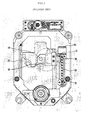
- Figs. 1 through 4 shows a prior optical writing/reading device.
- a prior optical writing/reading device includes an optical pick-up device 50, an optical pick-up motor 60 for moving the optical pick-up device to a proper position, a lead screw 20 connected to a rotational shaft of the optical pick-up motor 60, a rack gear 30 engaged with the lead screw 20, a guide feeder 10 coupled to the rack gear 30, an optical pick-up moving shaft 21 guiding a reciprocal motion of the guide feeder 10, and a main shaft 22 installed on an opposite side of the optical pick moving shaft 21 to guide the motion of the optical pick-up device.
- the lead screw 20 rotates and the rack gear 30 engaged with the lead screw 20 moves, thereby moving the optical pick-up device 50 to a desired position.
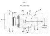
- the optical pick-up actuator 40 is comprised of a movable part moving a focus lens 49 in the focusing and tracking directions and a stationary part for supporting the movable part and generating magnetic field.
- the movable part has a coil cooperating with a permanent magnet 43 provided on the stationary part to locate the focus lens 49 to the desired position.
- the stationary part includes the permanent magnet 43 generating magnetic field, a yoke 42 forming a path of the magnetic field, the fixing frame 41 having a main board (not shown), and wire-shaped springs 47 each having a first end 47a fixed on the fixing frame 41 and a second end fixed on the lens holder 44 to support the lens holder 44 and supply electric current to the lens holder 44.
- the movable part includes the focus lens 49 focusing a laser beam eradiated from the laser diode on a recording layer of the optical disk, a lens holder 44 holding the focus lens 49, tracking coils 45 installed on both sides of the lens holder 44 to drive the lens holder 44 in the tracking direction, a focusing coil 46 wound around the lens holder 44 to drive the lens holder 44 in the focusing direction, and a spring fixing unit 48 fixing the spring assembly 47 on the lens holder 44.
- the movable part should be designed having a desired frequency property by being fixed by a support having a predetermined rigidity and a predetermined damping property.
- the movable part should be designed avoiding unnecessary vibration such as rotation or twist to effectively move in the focusing and tracking directions and reduce the optical signal error.
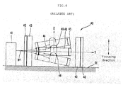
- the spring assembly 47 is comprised of two lower springs and two upper springs stacked on the lower springs that are installed on both sides of the lens holder 44, being extending from the fixing frame 41.
- springs 97 may be comprised of one lower spring and one upper spring stacked on the lower spring.
- the lens holder 44 may rotate in the direction of the X-axis, causing the undesired inclination.
- an elastic coefficient may be varied when the spring is twisted or tensioned during the manufacturing process.
- the present invention is directed to an actuator of an optical pick-up device that substantially obviates one or more problems due to limitations and disadvantages of the related art.
- An object of the present invention is to provide an actuator of an optical pick-up device, which can effectively drive the optical pick-up device and reduce the size of the optical pick-up device.
- an actuator of an optical pick-up device comprising: two fixing frames; a lens holder disposed between the fixing frames and provided with a focus lens and coils; springs supporting the lens holder, the springs connecting two points of each fixing frame to the lens holder, each spring having one or more bends; a permanent magnet disposed facing the coils to generate magnetic field; and a yoke forming a path of the magnetic field generated by the permanent magnet.
- an actuator of an optical pick-up device comprising: two fixing frames; lens holder disposed between the fixing frames and provided with a focus lens; springs supporting the lens holder by connecting the fixing frames to the lens holder; and a driving force generating unit including a coil and a permanent magnetic to generate driving force for moving the lens holder when control current is applied to the coil.
- an actuator of an optical pick-up device comprising: a fixing frame; a lens holder having a focus lens; springs connecting the fixing frame to the lens holder to support the lens holder; and a driving force generating unit including a coil and a permanent magnetic to generate driving force for moving the lens holder when control current is applied to the coil.
- Fig. 1 is a plane view of a prior optical writing/reading device
- Fig. 2 is a view of an actuator of a prior optical pick-up device
- Figs. 3 and 4 are views illustrating a focusing operation of an actuator of an prior optical pick-up device
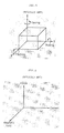
- Fig. 5 is a view illustrating rotational directions
- Fig. 6 is a view illustrating Lorentz force
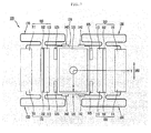
- Figs. 7 and 8 are views of an actuator of an optical pick-up device according to an embodiment of the present invention.
- Fig. 9 is a view illustrating a varied state of springs as a lens holder is driven in a focusing direction according to an embodiment of the present invention.
- Fig. 10 is a view illustrating a varied state of springs as a lens holder is driven in a tracking direction according to an embodiment of the present invention
- Fig. 11 is a view of a spring assembly of an actuator according to a modified example of the present invention.
- Figs. 12 through 14 show views illustrating a variety of springs according to modified examples of Fig. 11;
- Fig. 15 is a view of a spring of an actuator according to a modified example of the present invention.
- Fig. 16 is a view illustrating a varied state of springs depicted in Fig. 15 as a lens holder is driven in a focusing direction according to an embodiment of the present invention.
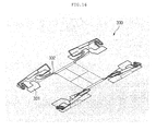
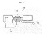
- Figs. 17 through 19 show an embodiment where damping material is deposited according to the present invention.
- Figs. 5 and 6 illustrates an operational theory of an actuator of an optical pick-up device.
- Fig. 5 illustrates rotational directions and
- Fig. 6 illustrates Lorentz force.
- Rotation around X, Y and Z-axes are respectively called a pitching, rolling and yawing.
- force applied to the actuator is generated by the combination of magnetic field formed by a permanent magnet and current flowing along a coil.
- Figs. 7 and 8 show an actuator of an optical pick-up device according to an embodiment of the present invention.
- the inventive optical pick-up actuator 100 includes a movable unit 120 equipped with a focus lens 121 to move in focusing and tracking directions 170 and 160 and a stationary unit 110 supporting the movable part 120 and generating magnetic field.
- the stationary unit 110 includes a pair of fixing frames 111 facing each other, a pair of permanent magnets 113 generating the magnetic field, a pair of yokes 112 fixed by pick-up bases 114 to generate a magnetic field path.
- Leaf springs 130 supports the movable part 120, each having first and second ends respectively fixed on the fixing frame 111 and a spring fixing portion 142 of a lens holder 122.
- each of the springs 130 is designed in a single step to overcome a space limitation by minimizing a thickness (in a direction of the Z-axis) of the lens holder 122.
- the lens holder 122 is designed to be supported at its four points to prevent the unexpected rotation from occurring and to perform the effective movement in the focusing and tracking directions 170 and 160.
- the movement range of the lens holder 122 can be enlarged by twist and bend variations at the bend portions 131, 132, 133, 134, 135, and 136 of the spring 130 without depending on a tensioning variation of the springs 130.
- the springs 130 are less sensitive with respect to a variation of an elastic coefficient according to the twist or bend of the springs 130 that may be incurred in the course of fixing the springs 130 on the lens holder 122 and the fixing frame 111, the driving property of the actuator can be improved.
- the spring 130 may be applied to a structure where a single fixing frame is formed as well as the structure where two fixing frames are formed.
- the springs 130 are installed on the same horizontal plane to effectively control the movement of the lens holder 122 and reduce the thickness of the lens holder 122.
- the spring fixing portions 142 where the first ends of the springs 130 are coupled to the lens holder 122 are preferably formed on the same horizontal plane.
- portions where the second ends of the springs 130 are fixed are preferably formed on the same horizontal plane as that where the spring fixing portions 142 are formed.
- the movable part 120 includes a focus lens 121 for focusing a laser beam on a recording layer of an optical disk, a lens holder 122 holding the focus lens 121, the lens holder 122 being controlled to be driven in he focusing and tracking direction 170 and 160, tracking coils 125 installed on front and rear surface of the lens holder 122 to drive the lens holder 122 in the tracking direction 160, a focusing coil wound around the lens holder 122 to drive the lens holder 122 in the focusing direction, and the spring fixing portions 142 formed on both ends of the lens holder 122 to connect the springs 130 to the lens holder 122.
- the one step springs 130 supports the both ends of the lens holder 122 to prevent the lens holder 122 from being unexpectedly inclined when the movable part 120 is driven.
- the actuator can be applied as a multiple driving shaft.
- the magnetic filed is formed around the lens holder 122 by the permanent magnets 113.
- the electromotive force is generated on the focusing coil 126 to drive the lens holder 122 in the focusing direction (in the vertical direction).
- the electromotive force is generated on the tracking coils 125 to drive the lens holder 122 in the tracking direction (in the left and right directions).
- the actuator drives the lens holder 122 to read data recorded on the recording layer of the optical disk by maintaining a focused spot formed on the focus lens 121 at a predetermined size.
- An actuator having the focusing and tracking coils formed on the lens holder such that the focusing and tracking coils move together with the lens holder is called a moving coil type actuator.
- An actuator having the permanent magnet formed on the lens holder 122 such that the permanent magnet moves together with the lens holder is called a moving magnet type actuator.
- Figs. 7 and 8 show such a moving coil type actuator.
- the present invention can be applied to the moving magnet type actuator by exchanging the locations of the permanent magnet with the coils.
- locations of the focusing and tracking coils 126 may be exchanged with each other according to a design selection.
- Fig. 9 illustrates a varied state of the springs 130 as the lens holder 122 is driven in the focusing direction according to an embodiment of the present invention
- Fig. 10 illustrates a varied state of the springs 130 as the lens holder 122 is driven in the tracking direction according to an embodiment of the present invention.
- Each of the springs 130 has the bends 131, 132, 133, 134, 135, and 136 so that the lens holder 122 can be effectively driven by the twist and bending of the bends 131, 132, 133, 134, 135, and 136.
- Fig. 11 shows a spring 230 of an optical pick-up actuator according to another embodiment of the present invention.
- the spring 230 is provided with a damping area 234 having a wider width. Damping material is deposited on the damping area 234.
- the spring 230 may have a variety of bends.
- Figs. 12 and 14 show a variety of modified examples of the springs having different damping areas formed according to the bends.
- the damping material such as gel type material is deposited on the damping area 234 and hardened by ultraviolet rays, thereby providing a damping property to the spring. Accordingly, the driving property of the actuator can be more improved.
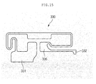
- Fig. 15 shows a modified example of the spring.
- a spring of this example has a lens holder coupling portion 332 having a width greater than a portion between the lens holder coupling portion 332 and the first bend 336.
- an effective area of the spring 330 is defined on a front end of the lens holder coupling portion 332.
- the spring coefficient K is generally determined at a less width portion of the spring. However, in this example, since the lens holder coupling portion 332 having the greater width is fixed on the lens holder, the spring coefficient K is increased, thereby reducing the fixed variation.
- the actuator of the present invention has less size and weight compared with the prior actuator.
- a mass portion of the springs is about 20-30% of the actuator. Accordingly, the vibration generated by the springs does not remarkably affect the driving property of the actuator.
- a stationary portion 331 is formed on a portion where the springs 330 are coupled to the fixing frame.
- the stationary portion 332 is coupled to the fixing frame, having a wider width than other portions.
- the stationary portion 332 is not affected by the movement of the lens holder, not functioning as the spring 330. That is, as shown in Fig. 16, as the lens holder moves, the spring 330 may be twisted or tensioned.
- the stationary portion 332 is not affected by the movement of the lens holder, being fixed on the fixing frame.
- a damper having the damping area 234 deposited with the damping material may be further formed to more effectively response to the vibration.
- Figs. 17 through 19 show an example where the damper is deposited on the damping area of the spring.
- Dampers 333, 334 and 335 are formed on at least two areas including a damping area 234 of the stationary portion 331 and a damping area 234 of the spring 330.
- the dampers 333 and 334 are formed on the damping area 234 of the stationary portion 331 and the damping area 234 of the spring 330.
- the dampers 335 are formed on the damping area 234 of the stationary portion 311 and two damping areas 234 of the spring 330.
- the springs are arranged on the same horizontal plane, a thickness of the actuator can be reduced.
- the actuator can be effectively driven.
- the lens holder coupling portion and the stationary portion makes the actuator more precisely driven with less vibration.
Landscapes
- Optical Recording Or Reproduction (AREA)
- Lens Barrels (AREA)
Applications Claiming Priority (6)
| Application Number | Priority Date | Filing Date | Title |
|---|---|---|---|
| KR2003070346 | 2003-10-09 | ||
| KR1020030070346A KR100548255B1 (ko) | 2003-10-09 | 2003-10-09 | 광픽업 장치의 액츄에이터 |
| KR1020040002677A KR100569919B1 (ko) | 2004-01-14 | 2004-01-14 | 광 디스크 드라이브 장치 |
| KR2004002677 | 2004-01-14 | ||
| KR2004002676 | 2004-01-14 | ||
| KR1020040002676A KR100569932B1 (ko) | 2004-01-14 | 2004-01-14 | 광 픽업 액츄에이터 장치 |
Publications (3)
| Publication Number | Publication Date |
|---|---|
| EP1522997A2 true EP1522997A2 (de) | 2005-04-13 |
| EP1522997A3 EP1522997A3 (de) | 2006-09-13 |
| EP1522997B1 EP1522997B1 (de) | 2009-07-15 |
Family
ID=34317272
Family Applications (1)
| Application Number | Title | Priority Date | Filing Date |
|---|---|---|---|
| EP04077733A Expired - Lifetime EP1522997B1 (de) | 2003-10-09 | 2004-10-08 | Aktuator einer optischen Abtastvorrichtung |
Country Status (4)
| Country | Link |
|---|---|
| US (1) | US7350222B2 (de) |
| EP (1) | EP1522997B1 (de) |
| CN (1) | CN1302470C (de) |
| DE (1) | DE602004022000D1 (de) |
Cited By (2)
| Publication number | Priority date | Publication date | Assignee | Title |
|---|---|---|---|---|
| EP1965378A1 (de) * | 2007-02-28 | 2008-09-03 | Deutsche Thomson OHG | Lesekopf für den Zugang zu beweglichen Speichermedien und Laufwerk mit dem Lesekopf |
| EP2100298A4 (de) * | 2006-12-20 | 2010-01-06 | Samsung Electronics Co Ltd | Optisches pickup-stellglied |
Families Citing this family (3)
| Publication number | Priority date | Publication date | Assignee | Title |
|---|---|---|---|---|
| WO2009139543A1 (ko) * | 2008-05-14 | 2009-11-19 | (주)하이소닉 | 떨림 보정기능이 구비된 영상 촬영 장치 |
| US7898752B2 (en) * | 2008-11-24 | 2011-03-01 | Corning Incorporated | Optical package comprising an adjustable lens component coupled to a multi-directional lens flexure |
| CN105721743B (zh) * | 2014-12-03 | 2020-01-21 | 佳能企业股份有限公司 | 摄像模块及应用其的电子装置 |
Family Cites Families (9)
| Publication number | Priority date | Publication date | Assignee | Title |
|---|---|---|---|---|
| JP2728496B2 (ja) | 1989-04-21 | 1998-03-18 | 株式会社日立製作所 | 対物レンズ駆動装置 |
| JP2981351B2 (ja) | 1992-10-22 | 1999-11-22 | シャープ株式会社 | 対物レンズ駆動装置 |
| JPH06162538A (ja) | 1992-11-19 | 1994-06-10 | Matsushita Electric Ind Co Ltd | 光ピックアップ用回動型アクチュエータ |
| KR970011821B1 (ko) * | 1994-11-17 | 1997-07-16 | 대우전자 주식회사 | 광디스크플레이어의 광픽업액츄에이터 |
| KR970002946U (ko) * | 1995-06-15 | 1997-01-24 | 광픽업 헤드의 3축 구동제어장치 | |
| KR100363154B1 (ko) * | 1998-08-13 | 2003-03-19 | 삼성전자 주식회사 | 광픽업의액츄에이터및그에따른구동코일권선방법 |
| US6801483B2 (en) | 2000-07-13 | 2004-10-05 | Lg Electronics Inc. | Optical pickup actuator performable tilting operation |
| JP2002133688A (ja) * | 2000-10-27 | 2002-05-10 | Hitachi Ltd | 対物レンズ駆動装置および光ディスク装置 |
| US7287264B2 (en) * | 2002-06-06 | 2007-10-23 | Ricoh Company, Ltd. | Objective lens drive apparatus with objective lens portion movable along support member axial direction |
-
2004
- 2004-10-07 US US10/961,951 patent/US7350222B2/en active Active
- 2004-10-08 DE DE602004022000T patent/DE602004022000D1/de not_active Expired - Lifetime
- 2004-10-08 EP EP04077733A patent/EP1522997B1/de not_active Expired - Lifetime
- 2004-10-09 CN CNB2004100808626A patent/CN1302470C/zh not_active Expired - Fee Related
Cited By (2)
| Publication number | Priority date | Publication date | Assignee | Title |
|---|---|---|---|---|
| EP2100298A4 (de) * | 2006-12-20 | 2010-01-06 | Samsung Electronics Co Ltd | Optisches pickup-stellglied |
| EP1965378A1 (de) * | 2007-02-28 | 2008-09-03 | Deutsche Thomson OHG | Lesekopf für den Zugang zu beweglichen Speichermedien und Laufwerk mit dem Lesekopf |
Also Published As
| Publication number | Publication date |
|---|---|
| EP1522997A3 (de) | 2006-09-13 |
| EP1522997B1 (de) | 2009-07-15 |
| US20050078571A1 (en) | 2005-04-14 |
| CN1302470C (zh) | 2007-02-28 |
| DE602004022000D1 (de) | 2009-08-27 |
| US7350222B2 (en) | 2008-03-25 |
| CN1606078A (zh) | 2005-04-13 |
Similar Documents
| Publication | Publication Date | Title |
|---|---|---|
| JP3791914B2 (ja) | 光ピックアップアクチュエータの3軸駆動装置 | |
| EP1522997B1 (de) | Aktuator einer optischen Abtastvorrichtung | |
| US7907479B2 (en) | Optical pickup actuator in writing and reading device | |
| US7414927B2 (en) | Actuator of optical pick-up device | |
| JP3566193B2 (ja) | 対物レンズ駆動装置及びそれを備えた光ディスク装置 | |
| KR100542012B1 (ko) | 광픽업 액츄에이터 지지구조 | |
| KR100548255B1 (ko) | 광픽업 장치의 액츄에이터 | |
| KR100624850B1 (ko) | 광 픽업 장치 | |
| KR100364353B1 (ko) | 광픽업 액츄에이터의 지지구조 | |
| KR100569920B1 (ko) | 광 디스크 드라이브 장치 | |
| KR100690595B1 (ko) | 광픽업용 엑츄에이터 | |
| JP2009187619A (ja) | 対物レンズ駆動装置及び光ピックアップ装置 | |
| KR100569932B1 (ko) | 광 픽업 액츄에이터 장치 | |
| KR100569919B1 (ko) | 광 디스크 드라이브 장치 | |
| WO2003052485A2 (en) | Adaptive optical scanning device | |
| JP3206933B2 (ja) | 光学ヘッド | |
| JPH01243246A (ja) | 光学系支持装置 | |
| KR100569921B1 (ko) | 광 디스크 드라이브 장치 | |
| KR20020038845A (ko) | 틸팅 구동이 가능한 액츄에이터의 지지구조 | |
| JPH08124193A (ja) | 二軸アクチュエータ | |
| KR20030021356A (ko) | 광픽업 액츄에이터의 지지구조 | |
| KR20040107324A (ko) | 광디스크 드라이브의 렌즈 돌출형 액츄에이터 | |
| JP2002025141A (ja) | 磁気ヘッド支持機構 | |
| KR20050074788A (ko) | 액츄에이터 및 광디스크 드라이브 장치 | |
| JPS61182641A (ja) | 対物レンズ支持装置 |
Legal Events
| Date | Code | Title | Description |
|---|---|---|---|
| PUAI | Public reference made under article 153(3) epc to a published international application that has entered the european phase |
Free format text: ORIGINAL CODE: 0009012 |
|
| AK | Designated contracting states |
Kind code of ref document: A2 Designated state(s): AT BE BG CH CY CZ DE DK EE ES FI FR GB GR HU IE IT LI LU MC NL PL PT RO SE SI SK TR |
|
| AX | Request for extension of the european patent |
Extension state: AL HR LT LV MK |
|
| PUAL | Search report despatched |
Free format text: ORIGINAL CODE: 0009013 |
|
| AK | Designated contracting states |
Kind code of ref document: A3 Designated state(s): AT BE BG CH CY CZ DE DK EE ES FI FR GB GR HU IE IT LI LU MC NL PL PT RO SE SI SK TR |
|
| AX | Request for extension of the european patent |
Extension state: AL HR LT LV MK |
|
| 17P | Request for examination filed |
Effective date: 20070313 |
|
| AKX | Designation fees paid |
Designated state(s): DE FR GB NL |
|
| 17Q | First examination report despatched |
Effective date: 20070511 |
|
| GRAP | Despatch of communication of intention to grant a patent |
Free format text: ORIGINAL CODE: EPIDOSNIGR1 |
|
| GRAS | Grant fee paid |
Free format text: ORIGINAL CODE: EPIDOSNIGR3 |
|
| GRAA | (expected) grant |
Free format text: ORIGINAL CODE: 0009210 |
|
| AK | Designated contracting states |
Kind code of ref document: B1 Designated state(s): DE FR GB NL |
|
| REG | Reference to a national code |
Ref country code: GB Ref legal event code: FG4D |
|
| REF | Corresponds to: |
Ref document number: 602004022000 Country of ref document: DE Date of ref document: 20090827 Kind code of ref document: P |
|
| NLV1 | Nl: lapsed or annulled due to failure to fulfill the requirements of art. 29p and 29m of the patents act | ||
| PG25 | Lapsed in a contracting state [announced via postgrant information from national office to epo] |
Ref country code: NL Free format text: LAPSE BECAUSE OF FAILURE TO SUBMIT A TRANSLATION OF THE DESCRIPTION OR TO PAY THE FEE WITHIN THE PRESCRIBED TIME-LIMIT Effective date: 20090715 |
|
| PLBE | No opposition filed within time limit |
Free format text: ORIGINAL CODE: 0009261 |
|
| STAA | Information on the status of an ep patent application or granted ep patent |
Free format text: STATUS: NO OPPOSITION FILED WITHIN TIME LIMIT |
|
| 26N | No opposition filed |
Effective date: 20100416 |
|
| REG | Reference to a national code |
Ref country code: FR Ref legal event code: PLFP Year of fee payment: 13 |
|
| REG | Reference to a national code |
Ref country code: FR Ref legal event code: PLFP Year of fee payment: 14 |
|
| REG | Reference to a national code |
Ref country code: FR Ref legal event code: PLFP Year of fee payment: 15 |
|
| PGFP | Annual fee paid to national office [announced via postgrant information from national office to epo] |
Ref country code: GB Payment date: 20220914 Year of fee payment: 19 |
|
| PGFP | Annual fee paid to national office [announced via postgrant information from national office to epo] |
Ref country code: FR Payment date: 20220916 Year of fee payment: 19 |
|
| PGFP | Annual fee paid to national office [announced via postgrant information from national office to epo] |
Ref country code: DE Payment date: 20220914 Year of fee payment: 19 |
|
| REG | Reference to a national code |
Ref country code: DE Ref legal event code: R119 Ref document number: 602004022000 Country of ref document: DE |
|
| GBPC | Gb: european patent ceased through non-payment of renewal fee |
Effective date: 20231008 |
|
| PG25 | Lapsed in a contracting state [announced via postgrant information from national office to epo] |
Ref country code: GB Free format text: LAPSE BECAUSE OF NON-PAYMENT OF DUE FEES Effective date: 20231008 |
|
| PG25 | Lapsed in a contracting state [announced via postgrant information from national office to epo] |
Ref country code: GB Free format text: LAPSE BECAUSE OF NON-PAYMENT OF DUE FEES Effective date: 20231008 Ref country code: FR Free format text: LAPSE BECAUSE OF NON-PAYMENT OF DUE FEES Effective date: 20231031 Ref country code: DE Free format text: LAPSE BECAUSE OF NON-PAYMENT OF DUE FEES Effective date: 20240501 |