EP1522833A1 - Vorrichtung zur Bestimmung der Fluoreszenzlebensdauer - Google Patents
Vorrichtung zur Bestimmung der Fluoreszenzlebensdauer Download PDFInfo
- Publication number
- EP1522833A1 EP1522833A1 EP04002203A EP04002203A EP1522833A1 EP 1522833 A1 EP1522833 A1 EP 1522833A1 EP 04002203 A EP04002203 A EP 04002203A EP 04002203 A EP04002203 A EP 04002203A EP 1522833 A1 EP1522833 A1 EP 1522833A1
- Authority
- EP
- European Patent Office
- Prior art keywords
- photons
- fluorescence lifetime
- excitation light
- time
- sample
- Prior art date
- Legal status (The legal status is an assumption and is not a legal conclusion. Google has not performed a legal analysis and makes no representation as to the accuracy of the status listed.)
- Withdrawn
Links
- 230000005284 excitation Effects 0.000 claims abstract description 43
- 238000005259 measurement Methods 0.000 claims abstract description 40
- 238000012937 correction Methods 0.000 claims abstract description 23
- 238000009826 distribution Methods 0.000 claims abstract description 21
- 238000001514 detection method Methods 0.000 claims abstract description 6
- 238000000034 method Methods 0.000 claims description 14
- 230000003287 optical effect Effects 0.000 claims description 2
- 230000001678 irradiating effect Effects 0.000 abstract description 3
- 238000012545 processing Methods 0.000 description 19
- 238000012986 modification Methods 0.000 description 7
- 230000004048 modification Effects 0.000 description 7
- 238000010586 diagram Methods 0.000 description 4
- 230000000694 effects Effects 0.000 description 4
- 230000005281 excited state Effects 0.000 description 3
- 230000005283 ground state Effects 0.000 description 3
- 230000008859 change Effects 0.000 description 2
- 230000007704 transition Effects 0.000 description 2
- 238000010276 construction Methods 0.000 description 1
- 238000007429 general method Methods 0.000 description 1
- 230000008569 process Effects 0.000 description 1
- 238000011160 research Methods 0.000 description 1
- 230000036962 time dependent Effects 0.000 description 1
Images


Classifications
-
- G—PHYSICS
- G01—MEASURING; TESTING
- G01N—INVESTIGATING OR ANALYSING MATERIALS BY DETERMINING THEIR CHEMICAL OR PHYSICAL PROPERTIES
- G01N21/00—Investigating or analysing materials by the use of optical means, i.e. using sub-millimetre waves, infrared, visible or ultraviolet light
- G01N21/62—Systems in which the material investigated is excited whereby it emits light or causes a change in wavelength of the incident light
- G01N21/63—Systems in which the material investigated is excited whereby it emits light or causes a change in wavelength of the incident light optically excited
- G01N21/64—Fluorescence; Phosphorescence
- G01N21/6408—Fluorescence; Phosphorescence with measurement of decay time, time resolved fluorescence
-
- G—PHYSICS
- G01—MEASURING; TESTING
- G01J—MEASUREMENT OF INTENSITY, VELOCITY, SPECTRAL CONTENT, POLARISATION, PHASE OR PULSE CHARACTERISTICS OF INFRARED, VISIBLE OR ULTRAVIOLET LIGHT; COLORIMETRY; RADIATION PYROMETRY
- G01J3/00—Spectrometry; Spectrophotometry; Monochromators; Measuring colours
- G01J3/28—Investigating the spectrum
- G01J3/44—Raman spectrometry; Scattering spectrometry ; Fluorescence spectrometry
- G01J3/4406—Fluorescence spectrometry
Definitions
- the present invention relates to an apparatus for measuring fluorescence lifetime based on number of measured photons generated from a sample by irradiating an excitation light on the sample.
- time gate method a pulse excitation light to irradiate the sample, and measures the number of photons emitted from the sample in plural time gates.
- the fluorescence lifetime is calculated based on the number of photons measured in the plural time gates.
- the time gate method can offer a fluorescence lifetime with a small error if time gates are properly set.
- the apparatus for measuring fluorescence lifetime includes a correction unit that acquires a first number of photons emitted from a sample excited by a pulse excitation light, and corrects the first number of photons into a second number of photons based on a predetermined probability distribution, and a calculation unit that calculates the fluorescence lifetime based on the second number of photons.
- the apparatus for measuring fluorescence lifetime includes a correction unit that acquires a first number of photons emitted from a sample excited by a pulse excitation light, and corrects the first number of photons into a second number of photons based on Poisson distribution, and a calculation unit that calculates the fluorescence lifetime based on the second number of photons.
- the apparatus for measuring fluorescence lifetime includes a pulse laser source that generates a pulse excitation light, an optical system that irradiates the pulse excitation light to a sample, a detector that detects a fluorescence generated from the sample, and outputs a detection signal corresponding to the fluorescence, a measurement unit that measures a first number of photons emitted from the sample in a predetermined time gate based on the detection signal, a correction unit that corrects the first number of photons into a second number of photons incorporating the first number of photons and number of irradiation times of the pulse excitation light, and a calculation unit that calculates the fluorescence lifetime of the sample based on the second number of photons.
- the method of measuring fluorescence lifetime includes measuring a first number of photons emitted from a sample excited by a pulse excitation light, correcting the first number of photons into a second number of photons based on a predetermined probability distribution, and calculating the fluorescence lifetime based on the second number of photons.
- FIG. 1 is a schematic diagram of a fluorescence lifetime measurement apparatus 1 according to an embodiment of the present invention.
- the fluorescence lifetime measurement apparatus 1 includes a measurement unit 2 that irradiates an excitation light on a sample to generate photons and detects the photons generated, a signal processing unit 4 that measures number of photons in plural time gates based on signals of the photons detected, an arithmetic processing unit 5 that calculates the fluorescence lifetime based on the number of photons measured in the plural time gates, and a control unit 3 that controls the measurement unit 2, the signal processing unit 4, and the arithmetic processing unit 5.
- the control unit 3 controls an emission timing of a pulse laser source 2a, time windows of the plural time gates, and processing of the arithmetic processing unit 5.
- the fluorescence lifetime measurement apparatus 1 includes the pulse laser source 2a, lens systems 2b and 2d, a sample 2c, and a detector 2e.
- Pulse excitation light emitted from the pulse laser source 2a is focused on the sample 2c by the lens system 2b.
- the sample 2c is excited by the pulse excitation light to be set in an excited state. In transition from the excited state to a ground state, the sample 2c emits photons with a predetermined probability distribution.
- the photons emitted from the sample 2c are condensed on the detector 2e by the lens system 2d.
- the detector 2e converts the photons into electric signals and outputs the electric signals to the signal processing unit 4.
- the signal processing unit 4 measures the number of photons in the plural time gates based on the electric signals and outputs the number of photons to the arithmetic processing unit 5.
- FIG. 2 is a block diagram of the signal processing unit 4 of the fluorescence lifetime measurement apparatus according to the embodiment.
- the signal processing unit 4 includes amplifiers 4a, 4b, and 4c, time gate switches S1 and S2, pulse height discriminators 4d and 4e, and counters 4f and 4g.
- the signal processing unit 4 amplifies the electric signals input from the detector 2e through the amplifier 4a and branches the electric signals through the time gate switches S1 and S2.
- the time gate switches S1 and S2 control timings of "ON" and “OFF” operations by a gate control signal from the control unit 3 and output the electric signals to the pulse height discriminators 4d and 4e via the amplifiers 4b and 4c in only an "ON" state.
- the periods of time of the "ON" operations of the time gate switches S1 and S2 correspond to the time gates, respectively.
- the pulse height discriminators 4d and 4e binarize the input electric signals by a predetermined time and output the binarized signals to the counters 4f and 4g, respectively.
- the counters 4f and 4g receive the binary signals, measure the number of photons in the time gates such that one photon is measured when the signal is input, and output the number of measured photons to the arithmetic processing unit 5.
- the arithmetic processing unit 5 detects the number of photons measured in the plural time gates set by the control unit 3 based on the number of photons input from the signal processing unit 4 in the time gates and calculates a fluorescence lifetime based on the number of photons in the time gates.
- the arithmetic processing unit 5 includes a correction unit 5a and a fluorescence lifetime calculation unit 5b.
- the correction unit 5a corrects the number of photons measured in the plural time gates to output the number of photons corrected to the fluorescence lifetime calculation unit 5b.
- the fluorescence lifetime calculation unit 5b calculates the fluorescence lifetime based on the number of photons corrected.
- the probability of emitting photons in a transition process from an excited state to a ground state is based on a Poisson distribution.
- energy of the pulse excitation light is increased, the probability of emitting photons becomes high.
- an error of measurement easily occurs in the number of photons.
- the energy of the pulse excitation light is reduced to a predetermined value to make the probability of emitting photons low. For this reason, a large amount of time is required to calculate a fluorescence lifetime.
- the distribution of the measured number of photons is corrected based on the Poisson distribution. For this reason, even though the number of photons are measured such that time gates each having a high probability of emitting photons are set, a fluorescence lifetime can be calculated within a short period of time with a small measurement error.
- the correction is performed such that a distribution of the number of photons input from the signal processing unit 4 and measured in plural time gates with respect to time follows the Poisson distribution.
- Pulse excitation light is irradiated N times, and the number of photons measured in a time gate ⁇ T is represented by k.
- the probability p(0, ⁇ )of no photon being incident in the time gate ⁇ T can be expressed by (4) from (1).
- p(0, ⁇ ) e - ⁇
- the correction unit 5a calculates (6) from the number N of times of irradiation of pulse excitation light input from the control unit 3 and the measured number k of photons input from the signal processing unit 4 and corrects the measured number k of photons to the number m of photons that are actually incident.
- the correction unit 5a outputs the number of photons which is corrected from k to m to the fluorescence lifetime calculation unit 5b.
- the fluorescence lifetime calculation unit 5b calculates the fluorescence lifetime based on the number of photons m.
- the correction unit 5a approximates (5) to a polynomial equation by a general method in place of calculation of (5) and calculates an approximate expression or calculates the value of the number ⁇ of photons with respect to a count rate x in advance to form a table.
- the table may be referred to without performing the calculation.
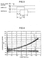
- FIG. 3 is a timing chart for illustrating "ON" and “OFF” status of a pulse laser source and time gate switches S1 and S2 of the fluorescence lifetime measurement apparatus according to the embodiment.
- the control unit 3 controls the emission timing of a laser beam from the pulse laser source 2a of the measurement unit 2 and the switches S1 and S2 of the control unit 3 to set the first time gate ⁇ T1, the second time gate ⁇ T2, and a time difference t.
- the correction unit 5a corrects the number k1 of photons measured by using (6) to m1. Similarly, the correction unit 5a corrects the number k2 into m2 and outputs the number m2 to the fluorescence lifetime calculation unit 5b.
- the corrected number of photons is corrected in accordance with the Poisson distribution, and the fluorescence lifetime ⁇ is calculated based on the corrected number of photons.
- the fluorescence lifetime ⁇ is calculated based on the corrected number of photons.
- the numbers m1 and m2 obtained by correcting the numbers k1 and k2 are used.
- the average numbers of photons being incident in the first time gate ⁇ T1 and the second time gate ⁇ T2 are given by ⁇ 1 and ⁇ 2, respectively, in single irradiation of pulse excitation light, the fluorescence lifetime ⁇ an also be calculated from the average values ⁇ 1 and ⁇ 2 based on the relationship expressed by (6) without calculating m1 and m2.
- FIG. 4 is a graph of fluorescence life vs. count rate for illustrating an effect of correction.
- the first time gate ⁇ T1 is set at 16 ns
- the second time gate ⁇ T2 is set at 16 ns
- the time difference t is set at 16 ns, so that the fluorescence lifetime is calculated.
- Respective plots are performed based on a measurement result of 131,072-times irradiation of pulse excitation light and the number of photons.
- a set of the plots illustrated in FIG. 4 indicates a fluorescence lifetime ⁇ 1 calculated based on the number of photons which is not corrected and a fluorescence lifetime ⁇ 2 calculated based on the number of photons which is corrected.
- the fluorescence lifetime ⁇ 2 corrected in FIG. 4 is 3.96 ns which is approximately constant regardless of the count rate x.
- the fluorescence lifetime ⁇ 1 which is not corrected increases with the increase of the count rate x. This means that when the count rate x is increased by increasing the probability of emitting photons, an error or measurement of photons increases.
- the count rate x is increased, the number of photons measured in the first time gate ⁇ T1 is relatively smaller than the number of photons measured in the second time gate ⁇ T2. As a result, the fluorescence lifetime ⁇ 1 increases.
- FIG. 5 is a graph of average fluorescence life vs. count rate for illustrating an effect of correction.
- Each plot indicates an average value obtained by the following manner. That is, 500,000-times irradiation of pulse excitation light and measurement of the number of photons are performed to calculate a fluorescence lifetime once, and the calculation of the fluorescence lifetime is performed 100 times.
- An average fluorescence lifetime ⁇ 1' calculated without correcting the measured number of photons and an average fluorescence lifetime ⁇ 2' calculated while correcting the number of photons are shown in FIG. 5.
- the calculated fluorescence lifetime increases with the increase of the count rate x to increase an error.
- the number of time gates is set at 2. However, when the number of time gates is 2, as is apparent from (8), only one fluorescence lifetime can be calculated from the number of photons.
- measurement can be performed employing two time gates. However, fluorescent materials of plural types may be contained in the same sample, and these fluorescent materials frequently have a different fluorescence lifetime.
- measurement is performed using at least three time gates. The measurement result is fitted by a function including a plurality of fluorescence lifetime components to calculate the fluorescence lifetime of the respective fluorescent components.
- P a probability of the photons from at least one component of the q components being incident on the time gate
- n (n is 2 or more) switches may be arranged to set n time gates.
- FIG. 6 is a timing chart for illustrating "ON" and "OFF" status of a pulse laser source and time gate switches S1 to Sn of the fluorescence lifetime measurement apparatus according to a first modification of the embodiment.
- time gates ⁇ T1 to ⁇ Tn can be set.
- the number of time gates increases, the number of photons in the time gates can be accurately measured. As a result, a fluorescence lifetime can be more accurately calculated.
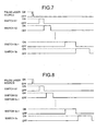
- FIG. 7 is a timing chart for illustrating "ON" and "OFF" status of a pulse laser source and time gate switches S1 to Sn of the fluorescence lifetime measurement apparatus according to a second modification of the embodiment.
- the lengths of the time gates are increased over time. In this manner, the number of photons can be measured in accordance with the probability of emitting photons. More specifically, the errors of the measured number of photons are to be uniformed. As a result, the fluorescence lifetime can be accurately calculated.
- FIG. 8 is a timing chart for illustrating "ON" and "OFF" status of a pulse laser source and time gate switches S1 to Sn of the fluorescence lifetime measurement apparatus according to a third modification of the embodiment.
- the lengths of the time gates are increased over time, and time zones in which the number of photons are not performed are set between the time gates. In this manner, the number of photons is prevented from being measured in plural time gates, and the number of photons can be more accurately measured.
Landscapes
- Physics & Mathematics (AREA)
- Spectroscopy & Molecular Physics (AREA)
- General Physics & Mathematics (AREA)
- Health & Medical Sciences (AREA)
- Nuclear Medicine, Radiotherapy & Molecular Imaging (AREA)
- Life Sciences & Earth Sciences (AREA)
- Chemical & Material Sciences (AREA)
- Analytical Chemistry (AREA)
- Biochemistry (AREA)
- General Health & Medical Sciences (AREA)
- Immunology (AREA)
- Pathology (AREA)
- Investigating, Analyzing Materials By Fluorescence Or Luminescence (AREA)
Applications Claiming Priority (2)
| Application Number | Priority Date | Filing Date | Title |
|---|---|---|---|
| JP2003348615 | 2003-10-07 | ||
| JP2003348615A JP3793531B2 (ja) | 2003-10-07 | 2003-10-07 | 蛍光寿命測定装置 |
Publications (1)
| Publication Number | Publication Date |
|---|---|
| EP1522833A1 true EP1522833A1 (de) | 2005-04-13 |
Family
ID=34309215
Family Applications (1)
| Application Number | Title | Priority Date | Filing Date |
|---|---|---|---|
| EP04002203A Withdrawn EP1522833A1 (de) | 2003-10-07 | 2004-01-30 | Vorrichtung zur Bestimmung der Fluoreszenzlebensdauer |
Country Status (3)
| Country | Link |
|---|---|
| US (1) | US7265825B2 (de) |
| EP (1) | EP1522833A1 (de) |
| JP (1) | JP3793531B2 (de) |
Cited By (2)
| Publication number | Priority date | Publication date | Assignee | Title |
|---|---|---|---|---|
| EP2365336A1 (de) * | 2010-03-10 | 2011-09-14 | Fujifilm Corporation | pH-Messung, Erkennung nicht normaler Bereiche, Verfahren und Vorrichtungen zur Analyse lebender Materie |
| CN109100028A (zh) * | 2018-08-28 | 2018-12-28 | 南昌大学 | 一种模拟单光子脉冲信号源的装置及方法 |
Families Citing this family (11)
| Publication number | Priority date | Publication date | Assignee | Title |
|---|---|---|---|---|
| JP4249103B2 (ja) * | 2003-08-08 | 2009-04-02 | オリンパス株式会社 | 蛍光寿命測定装置 |
| JP4323369B2 (ja) * | 2004-04-09 | 2009-09-02 | オリンパス株式会社 | 走査型蛍光顕微鏡装置 |
| US20100032584A1 (en) * | 2006-08-18 | 2010-02-11 | Macquarie University | Tiime gated fluorescent flow cytometer |
| KR100885927B1 (ko) | 2007-10-16 | 2009-02-26 | 광주과학기술원 | 형광수명 측정 방법 및 장치 |
| JP4523673B1 (ja) * | 2009-01-22 | 2010-08-11 | 三井造船株式会社 | 蛍光検出装置及び蛍光検出方法 |
| CN102292630A (zh) * | 2009-02-10 | 2011-12-21 | 三井造船株式会社 | 荧光检测装置及荧光检测方法 |
| JP6314872B2 (ja) * | 2015-02-25 | 2018-04-25 | 株式会社島津製作所 | 含有蛍光成分数決定方法及びその含有蛍光成分数決定方法を用いた分光蛍光光度計 |
| EP3465156B1 (de) * | 2016-05-25 | 2020-03-18 | Leica Microsystems CMS GmbH | Fluoreszenzlebensdauer-mikroskopieverfahren mit zeitkorrelierter einzelphotonenzählung welches höhere lichtintensitäten zulässt, und entsprechende vorrichtung |
| JP7510815B2 (ja) | 2020-02-20 | 2024-07-04 | 浜松ホトニクス株式会社 | 光干渉断層撮影装置 |
| CN115088249B (zh) | 2020-02-20 | 2025-04-25 | 浜松光子学株式会社 | 光学干涉断层摄影装置 |
| US12625074B2 (en) * | 2020-08-06 | 2026-05-12 | Hamamatsu Photonics K.K. | Time measurement device, fluorescence lifetime measurement device, and time measurement method |
Citations (2)
| Publication number | Priority date | Publication date | Assignee | Title |
|---|---|---|---|---|
| US4591984A (en) * | 1981-08-10 | 1986-05-27 | Tokyo Shibaura Denki Kabushiki Kaisha | Radiation measuring device |
| GB2382648A (en) | 2001-12-11 | 2003-06-04 | Amersham Pharm Biotech Uk Ltd | Time correlated multi-photon counting measurements |
Family Cites Families (4)
| Publication number | Priority date | Publication date | Assignee | Title |
|---|---|---|---|---|
| JP3742490B2 (ja) | 1997-07-22 | 2006-02-01 | 浜松ホトニクス株式会社 | 光波形計測装置 |
| AU4559600A (en) | 1999-04-29 | 2000-11-17 | Evotec Biosystems Ag | A method of characterizing fluorescent molecules or other particles using generating functions |
| US6690463B2 (en) | 2000-02-10 | 2004-02-10 | Evotec Biosystems Ag | Fluorescence intensity and lifetime distribution analysis |
| JP2003202292A (ja) | 2001-12-28 | 2003-07-18 | Hamamatsu Photonics Kk | 蛍光寿命測定装置および方法 |
-
2003
- 2003-10-07 JP JP2003348615A patent/JP3793531B2/ja not_active Expired - Fee Related
-
2004
- 2004-01-30 US US10/769,135 patent/US7265825B2/en not_active Expired - Lifetime
- 2004-01-30 EP EP04002203A patent/EP1522833A1/de not_active Withdrawn
Patent Citations (2)
| Publication number | Priority date | Publication date | Assignee | Title |
|---|---|---|---|---|
| US4591984A (en) * | 1981-08-10 | 1986-05-27 | Tokyo Shibaura Denki Kabushiki Kaisha | Radiation measuring device |
| GB2382648A (en) | 2001-12-11 | 2003-06-04 | Amersham Pharm Biotech Uk Ltd | Time correlated multi-photon counting measurements |
Non-Patent Citations (3)
| Title |
|---|
| "Journal of Microscopy", vol. 191, July 1998, WILEY-BLACKWELL PUBLISHING LTD, pages: 39 - 51 |
| GERRITSEN H C ET AL.: "Journal of Microscopy", vol. 206, June 2002, WILEY-BLACKWELL PUBLISHING LTD, article "Fluorescence lifetime imaging in scanning microscopes: acquisition speed, photon economy and lifetime resolution", pages: 218 - 224 |
| KELLER R A ET AL: "SINGLE-MOLECULE FLUORESCENCE ANALYSIS IN SOLUTION", APPLIED SPECTROSCOPY, THE SOCIETY FOR APPLIED SPECTROSCOPY. BALTIMORE, US, vol. 50, no. 7, July 1996 (1996-07-01), pages 12A - 32A, XP000642337, ISSN: 0003-7028 * |
Cited By (3)
| Publication number | Priority date | Publication date | Assignee | Title |
|---|---|---|---|---|
| EP2365336A1 (de) * | 2010-03-10 | 2011-09-14 | Fujifilm Corporation | pH-Messung, Erkennung nicht normaler Bereiche, Verfahren und Vorrichtungen zur Analyse lebender Materie |
| CN109100028A (zh) * | 2018-08-28 | 2018-12-28 | 南昌大学 | 一种模拟单光子脉冲信号源的装置及方法 |
| CN109100028B (zh) * | 2018-08-28 | 2020-06-16 | 南昌大学 | 一种模拟单光子脉冲信号源的装置及方法 |
Also Published As
| Publication number | Publication date |
|---|---|
| US20050072936A1 (en) | 2005-04-07 |
| JP2005114528A (ja) | 2005-04-28 |
| US7265825B2 (en) | 2007-09-04 |
| JP3793531B2 (ja) | 2006-07-05 |
Similar Documents
| Publication | Publication Date | Title |
|---|---|---|
| US7265825B2 (en) | Apparatus for measuring fluorescence lifetime | |
| EP1454128B1 (de) | Vorrichtung und Verfahren Für Messungen mit Zeitkorrelierter Multiphoton-Zählung | |
| US5990484A (en) | Method and apparatus for measuring fluorescence | |
| WO2016158421A1 (ja) | 光量検出装置、それを用いた免疫分析装置および荷電粒子線装置 | |
| JP2021535385A (ja) | 光子カウント光検出器を用いた寿命検出システムおよび方法 | |
| EP2522987A1 (de) | Fluoreszenzerkennungsvorrichtung, fluoreszenzerkennungsverfahren sowie verfahren zur verarbeitung von fluoreszenzsignalen | |
| CN111712705A (zh) | 采用时间相关的单光子计数的荧光寿命-显微-方法 | |
| CN113206442A (zh) | 激光驱动器脉冲成形控制 | |
| US20190310198A1 (en) | Fluorescence lifetime measurement apparatus and method capable of finding two or more fluorescence lifetime components by computing least square error through virtual fluorescence distribution model from signal collected in analog mean delay method | |
| EP2054715B1 (de) | System und verfahren zur kompensierung von systemverzögerungen bei der analytbestimmung | |
| KR101058672B1 (ko) | 시간 분해 측정 장치 | |
| US7215421B2 (en) | Fluorescence lifetime measurement apparatus | |
| US8624192B2 (en) | System for controlling photomultiplier gain drift and associated method | |
| JP4928502B2 (ja) | 液体シンチレーションカウンタ | |
| JP2002199187A (ja) | スキャナ装置 | |
| JP4704052B2 (ja) | 蛍光寿命測定装置 | |
| EP3611543A1 (de) | Röntgenanalysator und verfahren zum korrigieren der zählrate | |
| JP2006058046A (ja) | 超伝導x線分析装置及びx線分析方法 | |
| JP5026186B2 (ja) | 光学材料のレーザ損傷耐性推定方法及びレーザ損傷耐性推定装置 | |
| JP4065249B2 (ja) | 蛍光寿命測定装置 | |
| JP2002107300A (ja) | 蛍光寿命測定装置及び測定方法 | |
| KR20160014340A (ko) | 형광수명 분석 시스템 및 그 분석 방법 | |
| JPS63234241A (ja) | 蓄積性蛍光体シ−トの蓄積放射線エネルギ−レベル検出方法 | |
| JP6401606B2 (ja) | 蛍光ガラス線量計読取装置 | |
| EP3742204A1 (de) | Informationsaustausch mithilfe von gravitationswellen |
Legal Events
| Date | Code | Title | Description |
|---|---|---|---|
| PUAI | Public reference made under article 153(3) epc to a published international application that has entered the european phase |
Free format text: ORIGINAL CODE: 0009012 |
|
| AK | Designated contracting states |
Kind code of ref document: A1 Designated state(s): AT BE BG CH CY CZ DE DK EE ES FI FR GB GR HU IE IT LI LU MC NL PT RO SE SI SK TR |
|
| AX | Request for extension of the european patent |
Extension state: AL LT LV MK |
|
| 17P | Request for examination filed |
Effective date: 20050224 |
|
| AKX | Designation fees paid |
Designated state(s): AT BE BG CH CY CZ DE DK EE ES FI FR GB GR HU IE IT LI LU MC NL PT RO SE SI SK TR |
|
| 17Q | First examination report despatched |
Effective date: 20061207 |
|
| STAA | Information on the status of an ep patent application or granted ep patent |
Free format text: STATUS: THE APPLICATION HAS BEEN WITHDRAWN |
|
| 18W | Application withdrawn |
Effective date: 20160122 |