EP1522392A1 - Auflagevorrichtung für einen in Einzelstücke zu trennenden Gegenstand, vorzugsweise für einen Baumstamm - Google Patents
Auflagevorrichtung für einen in Einzelstücke zu trennenden Gegenstand, vorzugsweise für einen Baumstamm Download PDFInfo
- Publication number
- EP1522392A1 EP1522392A1 EP04011601A EP04011601A EP1522392A1 EP 1522392 A1 EP1522392 A1 EP 1522392A1 EP 04011601 A EP04011601 A EP 04011601A EP 04011601 A EP04011601 A EP 04011601A EP 1522392 A1 EP1522392 A1 EP 1522392A1
- Authority
- EP
- European Patent Office
- Prior art keywords
- support
- support elements
- frame
- support device
- individual pieces
- Prior art date
- Legal status (The legal status is an assumption and is not a legal conclusion. Google has not performed a legal analysis and makes no representation as to the accuracy of the status listed.)
- Granted
Links
- 238000000926 separation method Methods 0.000 description 3
- 238000000034 method Methods 0.000 description 2
- 238000002485 combustion reaction Methods 0.000 description 1
- 230000005484 gravity Effects 0.000 description 1
- 230000000284 resting effect Effects 0.000 description 1
Images
Classifications
-
- B—PERFORMING OPERATIONS; TRANSPORTING
- B27—WORKING OR PRESERVING WOOD OR SIMILAR MATERIAL; NAILING OR STAPLING MACHINES IN GENERAL
- B27B—SAWS FOR WOOD OR SIMILAR MATERIAL; COMPONENTS OR ACCESSORIES THEREFOR
- B27B21/00—Hand saws without power drive; Equipment for hand sawing, e.g. saw horses
-
- B—PERFORMING OPERATIONS; TRANSPORTING
- B27—WORKING OR PRESERVING WOOD OR SIMILAR MATERIAL; NAILING OR STAPLING MACHINES IN GENERAL
- B27B—SAWS FOR WOOD OR SIMILAR MATERIAL; COMPONENTS OR ACCESSORIES THEREFOR
- B27B17/00—Chain saws; Equipment therefor
- B27B17/0041—Saw benches or saw bucks
-
- B—PERFORMING OPERATIONS; TRANSPORTING
- B27—WORKING OR PRESERVING WOOD OR SIMILAR MATERIAL; NAILING OR STAPLING MACHINES IN GENERAL
- B27B—SAWS FOR WOOD OR SIMILAR MATERIAL; COMPONENTS OR ACCESSORIES THEREFOR
- B27B29/00—Gripping, clamping or holding devices for the trunk or log in saw mills or sawing machines; Travelling trunk or log carriages
Definitions
- the invention relates to a support device for one in individual pieces separating object, preferably for a tree trunk, with a Frame having support elements for the object.
- Different items can not be used as a whole. she are to be separated into individual pieces, or divided, to these individual pieces to be able to apply. For example, if the item is around a tree trunk or a larger tree branch, so is one Use of this tree trunk or tree branch as firewood not in the Whole possible.
- the tree trunk into individual pieces for example in To divide tree trunk disks to separate them one from the other further processing or even their combustion in a stove supply.
- the invention is based on the object, a support device of show the aforementioned genus, with the separation of a Object is facilitated in individual pieces and perform faster is.
- the support elements are formed separately from each other and that the support elements so on Rack are arranged, that between each adjacent Support elements an optionally trained distance is present.
- support device In the support device according to the invention are in addition to the actual Frame separate support elements present, which is a special arrangement exhibit.
- the support elements are not integral as one Saw saw trained, rather is a separate from each other Training the support elements before. It is between each other adjacent support elements formed a distance.
- the support device is to be separated Object, preferably tree trunk, thus of several Supported elements, wherein the support elements each one Distance between them.
- This distance can be a Separating member, such as a chainsaw, are passed, with which the item is separated into individual pieces.
- the object remains advantageous in its original edition on the Support device, a tracking of the object is not required.
- the distance between the adjacent support elements is optional education. By setting this distance is determinable which dimensions the individual pieces after the separation of the object exhibit.
- the support elements can also be displaced on the frame be arranged so that the distance between adjacent ones Support elements changed without an exchange of the support elements can be. After moving a support element this can be fixed again on the frame, for example with suitable Fasteners. But the support elements and the frame can also be formed integrally. Then it may be possible to appropriate Frame sections with the support elements to make interchangeable.
- a next development of the invention provides that each support element having planar sections, the bearing surfaces for the to be separated Object and for the individual pieces after separating the object form.
- the object to be separated is placed on the support elements hung up.
- These have, according to this development, planar sections, so that they are able, even the individual pieces after separating the To wear object without these of the invention Fall down support device.
- the launched on the support elements Subject may thus, for example, with a saw in subsequent Sawing operations are divided into individual pieces without the object to move or move is.
- the separated individual pieces are after the sawing operations on the support elements and can subsequently be removed from these.
- the inventive Device carries the individual pieces thus in the manner of an egg cutter.
- at the support device according to the invention can be an object in For example, disc-shaped individual pieces are separated, each after the separation of the object present single piece on a Support element rests.
- Each support element is preferably V-shaped in section, wherein the V-legs provide the bearing surfaces.
- a V-shaped Supporting element an elongate object can be inserted positively become.
- this article a radially symmetric one Subject, for example, a tree trunk with about circular cross-section, so the V-legs can tangentially to the Create surface of the resting object.
- Gravity will be at a heavy subject, as in a tree trunk, prevents it from hanging up after it has landed moves, for example, twisted. But there may also be additional holding means be provided for the object to be separated, for example suitable straps.
- the frame is formed torartig, wherein it is in the region of the horizontally extending Torabiteses has a lowered area in which Support elements are located.
- the frame is for example by a profile formed, which has sufficient dimensions for applying the having required forces.
- By lowering in the horizontal extending gate section are incorporated into the frame bends, which increase the mechanical strength of the frame.
- the lowering support elements are arranged so that a uniform Supporting the object to be separated over its length is given.
- the arranged by the lowered area support elements provided bearing surfaces are preferably approximately in a height level with the non-lowered areas of the horizontally extending Torabroughes arranged.
- further support elements can be arranged be. Due to the height arrangement arranged in the lowered area Support elements is ensured that all support elements in one Height are so that a tree trunk can be placed on this.
- the Support elements are also arranged approximately in a line.
- the separating device can be, for example, a splitting device, which includes a hydraulic press. With this splitting device can sawn tree trunk slices split into individual logs become.
- the Separating device approximately in the height level of the non-lowered areas of the horizontally extending Torabiteses is arranged.
- the Separator is then in the same height level as the after Dividing the object separated from each other individual pieces.
- the Individual pieces can then be placed in this height level Separating device are supplied, a lifting of the individual pieces advantageously avoided.
- FIG. 1 An embodiment of the invention, from which further inventive Give characteristics is shown in the drawing.
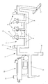
- the only figure of the Drawing shows a perspective side view of a support device for an item to be separated into individual pieces.
- the support device shown in the drawing has a frame 1.
- the frame 1 is made of a multi-angled profile 2 with rectangular Cross section formed.
- the frame 1 is basically formed like a torus, in the horizontally extending gate section is a lowered area. 3 arranged. In this area 3, the profile 2 has a U-shaped course on.
- the frame 1 carries five support elements 5.
- the support elements 5 have to each other angled salaried sections 6, wherein the flat Sections 6 of a support element 5 each to each other in V-shape are arranged.
- the flat sections 6 of each support element. 5 include, for example, an angle of 45 °.
- Some of the support elements 5 are on vertically aligned profiles 7 the lowered area 3 is arranged.
- the profiles 7 are dimensioned such that all support elements 5 are arranged in a height plane.
- On the lowered area 3 of the profile 2 are still exposed wooden beams 8, which a z. B. between the profiles 7 down moving chainsaw before, components of the chainsaw by hitting the profile 2 to be damaged.
- an auxiliary frame 9 is attached laterally, which is substantially is designed as an L-profile.
- This auxiliary frame 9 carries a splitter 10, with which z. B. logs are split into logs can.
- the splitter 10 is motorized, it has For example, a hydraulic press. With this z. B. Tree trunk disks are pressed against a wedge 11.
Landscapes
- Life Sciences & Earth Sciences (AREA)
- Engineering & Computer Science (AREA)
- Mechanical Engineering (AREA)
- Wood Science & Technology (AREA)
- Forests & Forestry (AREA)
- Debarking, Splitting, And Disintegration Of Timber (AREA)
- De-Stacking Of Articles (AREA)
- Catching Or Destruction (AREA)
- Combined Means For Separation Of Solids (AREA)
- Supports For Plants (AREA)
Abstract
Description
Claims (11)
- Auflagevorrichtung für einen in Einzelstücke zu trennenden Gegenstand, vorzugsweise für einen Baumstamm, mit einem Gestell (1), das Auflageelemente (5) für den Gegenstand aufweist,
dadurch gekennzeichnet, daß die Auflageelemente (5) voneinander separat ausgebildet sind und daß die Auflageelemente (5) derart am Gestell (1) angeordnet sind, daß jeweils zwischen einander benachbarten Auflageelementen (5) ein wahlfrei ausgebildeter Abstand vorhanden ist. - Auflagevorrichtung nach Anspruch 1, dadurch gekennzeichnet, daß die Auflageelemente (5) und das Gestell (1) einstückig ausgebildet sind.
- Auflagevorrichtung nach Anspruch 1, dadurch gekennzeichnet, daß die Auflageelemente (5) an dem Gestell (1) mit Befestigungsmitteln angeschlagen sind.
- Auflagevorrichtung nach einem der vorhergehenden Ansprüche, dadurch gekennzeichnet, daß jedes Auflageelement (5) flächige Abschnitte (6) aufweist, die Auflageflächen für den zu trennenden Gegenstand und für die Einzelstücke nach dem Trennen des Gegenstandes ausbilden.
- Auflagevorrichtung nach Anspruch 4, dadurch gekennzeichnet, daß jedes Auflageelement (5) im Schnitt V-förmig ausgebildet ist, wobei die V-Schenkel die Auflageflächen bereitstellen.
- Auflagevorrichtung nach einem der vorhergehenden Ansprüche, dadurch gekennzeichnet, daß das Gestell (1) torartig ausgebildet ist, wobei es im Bereich des horizontal verlaufenden Torabschnittes einen abgesenkten Bereich (3) aufweist, in dem sich Auflageelemente (5) befinden.
- Auflagevorrichtung nach Anspruch 6, dadurch gekennzeichnet, daß die von den im abgesenkten Bereich (3) angeordneten Auflageelementen (5) bereitgestellten Auflageflächen etwa in einer Höhenebene mit den nicht abgesenkten Bereichen des horizontal verlaufenden Torabschnittes angeordnet sind.
- Auflagevorrichtung nach einem der vorhergehenden Ansprüche, dadurch gekennzeichnet, daß an dem Gestell (1) wenigstens eine Trenneinrichtung für die Einzelstücke angeordnet ist.
- Auflagevorrichtung nach Anspruch 8, dadurch gekennzeichnet, daß die Trenneinrichtung eine Spalteinrichtung (10) ist.
- Auflagevorrichtung nach Anspruch 9, dadurch gekennzeichnet, daß die Spalteinrichtung (10) eine Hydraulikpresse umfaßt.
- Auflagevorrichtung nach einem der Ansprüche 7 und 8 bis 10, dadurch gekennzeichnet, daß die Trenneinrichtung etwa in der Höhenebene der nicht abgesenkten Bereiche des horizontal verlaufenden Torabschnittes angeordnet ist.
Applications Claiming Priority (4)
| Application Number | Priority Date | Filing Date | Title |
|---|---|---|---|
| DE20315616U | 2003-10-10 | ||
| DE20315616 | 2003-10-10 | ||
| DE202004005124U | 2004-04-01 | ||
| DE200420005124 DE202004005124U1 (de) | 2004-04-01 | 2004-04-01 | Holzsägebock mit Vorrichtung Hydraulikpresse |
Publications (2)
| Publication Number | Publication Date |
|---|---|
| EP1522392A1 true EP1522392A1 (de) | 2005-04-13 |
| EP1522392B1 EP1522392B1 (de) | 2006-08-30 |
Family
ID=34315117
Family Applications (1)
| Application Number | Title | Priority Date | Filing Date |
|---|---|---|---|
| EP04011601A Expired - Lifetime EP1522392B1 (de) | 2003-10-10 | 2004-05-15 | Auflagevorrichtung für einen in Einzelstücke zu trennenden Gegenstand, vorzugsweise für einen Baumstamm |
Country Status (3)
| Country | Link |
|---|---|
| EP (1) | EP1522392B1 (de) |
| AT (1) | ATE337894T1 (de) |
| DE (1) | DE502004001323D1 (de) |
Citations (8)
| Publication number | Priority date | Publication date | Assignee | Title |
|---|---|---|---|---|
| US4066110A (en) * | 1958-10-24 | 1978-01-03 | Sarno Richard L | Apparatus for splitting logs |
| US4121814A (en) * | 1978-01-30 | 1978-10-24 | Prior Herbert E | Sawbuck |
| FR2437915A1 (fr) * | 1978-10-03 | 1980-04-30 | Rafer Chaines Roues Dentees | Chevalet de sciage |
| FR2516850A1 (fr) * | 1981-11-20 | 1983-05-27 | Allko Metallkonstruktionen Gmb | Chevalet de support repliable en profiles d'aluminium pour sciage de buches |
| AT377940B (de) * | 1983-11-22 | 1985-05-28 | Grill Hermann | Saegebock |
| US4638885A (en) * | 1984-12-06 | 1987-01-27 | Frederick Raymond L | Combination sawhorse and sawbuck |
| US4653556A (en) * | 1986-03-03 | 1987-03-31 | Provolt Monte B | Log splitting machine |
| US4890952A (en) * | 1988-03-11 | 1990-01-02 | Jones Richard G | Sawbuck construction and bracket |
-
2004
- 2004-05-15 DE DE502004001323T patent/DE502004001323D1/de not_active Expired - Lifetime
- 2004-05-15 AT AT04011601T patent/ATE337894T1/de not_active IP Right Cessation
- 2004-05-15 EP EP04011601A patent/EP1522392B1/de not_active Expired - Lifetime
Patent Citations (8)
| Publication number | Priority date | Publication date | Assignee | Title |
|---|---|---|---|---|
| US4066110A (en) * | 1958-10-24 | 1978-01-03 | Sarno Richard L | Apparatus for splitting logs |
| US4121814A (en) * | 1978-01-30 | 1978-10-24 | Prior Herbert E | Sawbuck |
| FR2437915A1 (fr) * | 1978-10-03 | 1980-04-30 | Rafer Chaines Roues Dentees | Chevalet de sciage |
| FR2516850A1 (fr) * | 1981-11-20 | 1983-05-27 | Allko Metallkonstruktionen Gmb | Chevalet de support repliable en profiles d'aluminium pour sciage de buches |
| AT377940B (de) * | 1983-11-22 | 1985-05-28 | Grill Hermann | Saegebock |
| US4638885A (en) * | 1984-12-06 | 1987-01-27 | Frederick Raymond L | Combination sawhorse and sawbuck |
| US4653556A (en) * | 1986-03-03 | 1987-03-31 | Provolt Monte B | Log splitting machine |
| US4890952A (en) * | 1988-03-11 | 1990-01-02 | Jones Richard G | Sawbuck construction and bracket |
Also Published As
| Publication number | Publication date |
|---|---|
| EP1522392B1 (de) | 2006-08-30 |
| ATE337894T1 (de) | 2006-09-15 |
| DE502004001323D1 (de) | 2006-10-12 |
Similar Documents
| Publication | Publication Date | Title |
|---|---|---|
| EP1837147B1 (de) | Holzspalter | |
| WO2010009861A1 (de) | Kapp- und gehrungssäge | |
| EP1522392A1 (de) | Auflagevorrichtung für einen in Einzelstücke zu trennenden Gegenstand, vorzugsweise für einen Baumstamm | |
| EP0064480A2 (de) | Sägebock | |
| DE3046655A1 (de) | Haltevorrichtung zum halten laengerer holzteile fuer die querunterteilung mit einem schneidwerkzeug wie einer motorsaege | |
| DE3040913A1 (de) | Verfahren und vorrichtung zum zerteilen von holzfasermaterial | |
| DE102009050707A1 (de) | Vorrichtung zum Herstellen von Kamin- und Ofenbrennholz | |
| DE3013375C2 (de) | Vorrichtung zum Zerkleinern von Holz | |
| AT413803B (de) | Spaltvorrichtung für holzstämme | |
| DE375241C (de) | Vorrichtung zum Entrinden von Baumstaemmen | |
| DE2428440A1 (de) | Vorrichtung zur materialaustragung an holz-saegewerksmaschinen | |
| DE102008063511B3 (de) | Vorrichtung zum Zerlegen von Baumstämmen | |
| DE2916831A1 (de) | Saegebock | |
| AT517195B1 (de) | Holzspalter mit Holzzentriervorrichtung | |
| DE29810464U1 (de) | Vorrichtung zum Sägen von Kaminholz o.dgl. | |
| DE102017127249B4 (de) | Holzschneider | |
| CH147875A (de) | Einrichtung zum Schneiden von Zapfen bei Holzbalken. | |
| DE102006001025B3 (de) | Holzspaltvorrichtung | |
| AT511247B1 (de) | Vorrichtung zum zuschneiden von isoliermaterialien | |
| DE2165557B2 (de) | Vorrichtung zum Entrinden von Nadelschwachholz | |
| DE19923367A1 (de) | Sägegestell | |
| DE202020000288U1 (de) | Zündholzvorrichtung für stehende Holzspalter | |
| DE3529100A1 (de) | Vorrichtung zur durchfuehrung von laengsschnitten in holz | |
| DE102017125315A1 (de) | Vorrichtung zum Verarbeiten von Holz | |
| DE202019105352U1 (de) | Vorrichtung zur Aufnahme von Spalt- und Hilfswerkzeugen, insbesondere beim Zurichten von Brennholz |
Legal Events
| Date | Code | Title | Description |
|---|---|---|---|
| PUAI | Public reference made under article 153(3) epc to a published international application that has entered the european phase |
Free format text: ORIGINAL CODE: 0009012 |
|
| AK | Designated contracting states |
Kind code of ref document: A1 Designated state(s): AT BE BG CH CY CZ DE DK EE ES FI FR GB GR HU IE IT LI LU MC NL PL PT RO SE SI SK TR |
|
| AX | Request for extension of the european patent |
Extension state: AL HR LT LV MK |
|
| 17P | Request for examination filed |
Effective date: 20050518 |
|
| AKX | Designation fees paid |
Designated state(s): AT BE BG CH CY CZ DE DK EE ES FI FR GB GR HU IE IT LI LU MC NL PL PT RO SE SI SK TR |
|
| AXX | Extension fees paid |
Extension state: AL Payment date: 20050518 Extension state: MK Payment date: 20050518 Extension state: LV Payment date: 20050518 Extension state: LT Payment date: 20050518 Extension state: HR Payment date: 20050518 |
|
| GRAP | Despatch of communication of intention to grant a patent |
Free format text: ORIGINAL CODE: EPIDOSNIGR1 |
|
| GRAS | Grant fee paid |
Free format text: ORIGINAL CODE: EPIDOSNIGR3 |
|
| GRAA | (expected) grant |
Free format text: ORIGINAL CODE: 0009210 |
|
| AK | Designated contracting states |
Kind code of ref document: B1 Designated state(s): AT BE BG CH CY CZ DE DK EE ES FI FR GB GR HU IE IT LI LU MC NL PL PT RO SE SI SK TR |
|
| AX | Request for extension of the european patent |
Extension state: AL HR LT LV MK |
|
| PG25 | Lapsed in a contracting state [announced via postgrant information from national office to epo] |
Ref country code: IT Free format text: LAPSE BECAUSE OF FAILURE TO SUBMIT A TRANSLATION OF THE DESCRIPTION OR TO PAY THE FEE WITHIN THE PRESCRIBED TIME-LIMIT;WARNING: LAPSES OF ITALIAN PATENTS WITH EFFECTIVE DATE BEFORE 2007 MAY HAVE OCCURRED AT ANY TIME BEFORE 2007. THE CORRECT EFFECTIVE DATE MAY BE DIFFERENT FROM THE ONE RECORDED. Effective date: 20060830 Ref country code: CZ Free format text: LAPSE BECAUSE OF FAILURE TO SUBMIT A TRANSLATION OF THE DESCRIPTION OR TO PAY THE FEE WITHIN THE PRESCRIBED TIME-LIMIT Effective date: 20060830 Ref country code: PL Free format text: LAPSE BECAUSE OF FAILURE TO SUBMIT A TRANSLATION OF THE DESCRIPTION OR TO PAY THE FEE WITHIN THE PRESCRIBED TIME-LIMIT Effective date: 20060830 Ref country code: RO Free format text: LAPSE BECAUSE OF FAILURE TO SUBMIT A TRANSLATION OF THE DESCRIPTION OR TO PAY THE FEE WITHIN THE PRESCRIBED TIME-LIMIT Effective date: 20060830 Ref country code: SI Free format text: LAPSE BECAUSE OF FAILURE TO SUBMIT A TRANSLATION OF THE DESCRIPTION OR TO PAY THE FEE WITHIN THE PRESCRIBED TIME-LIMIT Effective date: 20060830 Ref country code: FI Free format text: LAPSE BECAUSE OF FAILURE TO SUBMIT A TRANSLATION OF THE DESCRIPTION OR TO PAY THE FEE WITHIN THE PRESCRIBED TIME-LIMIT Effective date: 20060830 Ref country code: NL Free format text: LAPSE BECAUSE OF FAILURE TO SUBMIT A TRANSLATION OF THE DESCRIPTION OR TO PAY THE FEE WITHIN THE PRESCRIBED TIME-LIMIT Effective date: 20060830 Ref country code: IE Free format text: LAPSE BECAUSE OF FAILURE TO SUBMIT A TRANSLATION OF THE DESCRIPTION OR TO PAY THE FEE WITHIN THE PRESCRIBED TIME-LIMIT Effective date: 20060830 |
|
| REG | Reference to a national code |
Ref country code: GB Ref legal event code: FG4D Free format text: NOT ENGLISH |
|
| REG | Reference to a national code |
Ref country code: CH Ref legal event code: EP |
|
| REG | Reference to a national code |
Ref country code: IE Ref legal event code: FG4D Free format text: LANGUAGE OF EP DOCUMENT: GERMAN |
|
| REF | Corresponds to: |
Ref document number: 502004001323 Country of ref document: DE Date of ref document: 20061012 Kind code of ref document: P |
|
| PG25 | Lapsed in a contracting state [announced via postgrant information from national office to epo] |
Ref country code: DK Free format text: LAPSE BECAUSE OF FAILURE TO SUBMIT A TRANSLATION OF THE DESCRIPTION OR TO PAY THE FEE WITHIN THE PRESCRIBED TIME-LIMIT Effective date: 20061130 Ref country code: BG Free format text: LAPSE BECAUSE OF FAILURE TO SUBMIT A TRANSLATION OF THE DESCRIPTION OR TO PAY THE FEE WITHIN THE PRESCRIBED TIME-LIMIT Effective date: 20061130 |
|
| PG25 | Lapsed in a contracting state [announced via postgrant information from national office to epo] |
Ref country code: ES Free format text: LAPSE BECAUSE OF FAILURE TO SUBMIT A TRANSLATION OF THE DESCRIPTION OR TO PAY THE FEE WITHIN THE PRESCRIBED TIME-LIMIT Effective date: 20061211 |
|
| REG | Reference to a national code |
Ref country code: SE Ref legal event code: TRGR |
|
| PG25 | Lapsed in a contracting state [announced via postgrant information from national office to epo] |
Ref country code: PT Free format text: LAPSE BECAUSE OF FAILURE TO SUBMIT A TRANSLATION OF THE DESCRIPTION OR TO PAY THE FEE WITHIN THE PRESCRIBED TIME-LIMIT Effective date: 20070206 |
|
| LTIE | Lt: invalidation of european patent or patent extension |
Effective date: 20060830 |
|
| NLV1 | Nl: lapsed or annulled due to failure to fulfill the requirements of art. 29p and 29m of the patents act | ||
| ET | Fr: translation filed | ||
| REG | Reference to a national code |
Ref country code: IE Ref legal event code: FD4D |
|
| PLBE | No opposition filed within time limit |
Free format text: ORIGINAL CODE: 0009261 |
|
| STAA | Information on the status of an ep patent application or granted ep patent |
Free format text: STATUS: NO OPPOSITION FILED WITHIN TIME LIMIT |
|
| 26N | No opposition filed |
Effective date: 20070531 |
|
| BERE | Be: lapsed |
Owner name: JANSSEN, MARCO Effective date: 20070531 Owner name: JANSSEN, GERHARD Effective date: 20070531 |
|
| PG25 | Lapsed in a contracting state [announced via postgrant information from national office to epo] |
Ref country code: MC Free format text: LAPSE BECAUSE OF NON-PAYMENT OF DUE FEES Effective date: 20070531 |
|
| PG25 | Lapsed in a contracting state [announced via postgrant information from national office to epo] |
Ref country code: BE Free format text: LAPSE BECAUSE OF NON-PAYMENT OF DUE FEES Effective date: 20070531 |
|
| PG25 | Lapsed in a contracting state [announced via postgrant information from national office to epo] |
Ref country code: GR Free format text: LAPSE BECAUSE OF FAILURE TO SUBMIT A TRANSLATION OF THE DESCRIPTION OR TO PAY THE FEE WITHIN THE PRESCRIBED TIME-LIMIT Effective date: 20061201 |
|
| PG25 | Lapsed in a contracting state [announced via postgrant information from national office to epo] |
Ref country code: EE Free format text: LAPSE BECAUSE OF FAILURE TO SUBMIT A TRANSLATION OF THE DESCRIPTION OR TO PAY THE FEE WITHIN THE PRESCRIBED TIME-LIMIT Effective date: 20060830 |
|
| PG25 | Lapsed in a contracting state [announced via postgrant information from national office to epo] |
Ref country code: AT Free format text: LAPSE BECAUSE OF NON-PAYMENT OF DUE FEES Effective date: 20070515 |
|
| REG | Reference to a national code |
Ref country code: CH Ref legal event code: PL |
|
| PG25 | Lapsed in a contracting state [announced via postgrant information from national office to epo] |
Ref country code: LI Free format text: LAPSE BECAUSE OF NON-PAYMENT OF DUE FEES Effective date: 20080531 Ref country code: CH Free format text: LAPSE BECAUSE OF NON-PAYMENT OF DUE FEES Effective date: 20080531 |
|
| PG25 | Lapsed in a contracting state [announced via postgrant information from national office to epo] |
Ref country code: LU Free format text: LAPSE BECAUSE OF NON-PAYMENT OF DUE FEES Effective date: 20070515 Ref country code: CY Free format text: LAPSE BECAUSE OF FAILURE TO SUBMIT A TRANSLATION OF THE DESCRIPTION OR TO PAY THE FEE WITHIN THE PRESCRIBED TIME-LIMIT Effective date: 20060830 |
|
| PG25 | Lapsed in a contracting state [announced via postgrant information from national office to epo] |
Ref country code: TR Free format text: LAPSE BECAUSE OF FAILURE TO SUBMIT A TRANSLATION OF THE DESCRIPTION OR TO PAY THE FEE WITHIN THE PRESCRIBED TIME-LIMIT Effective date: 20060830 Ref country code: HU Free format text: LAPSE BECAUSE OF FAILURE TO SUBMIT A TRANSLATION OF THE DESCRIPTION OR TO PAY THE FEE WITHIN THE PRESCRIBED TIME-LIMIT Effective date: 20070301 |
|
| PGFP | Annual fee paid to national office [announced via postgrant information from national office to epo] |
Ref country code: SK Payment date: 20120514 Year of fee payment: 9 |
|
| PGFP | Annual fee paid to national office [announced via postgrant information from national office to epo] |
Ref country code: FR Payment date: 20120608 Year of fee payment: 9 |
|
| PG25 | Lapsed in a contracting state [announced via postgrant information from national office to epo] |
Ref country code: SK Free format text: LAPSE BECAUSE OF NON-PAYMENT OF DUE FEES Effective date: 20130515 |
|
| REG | Reference to a national code |
Ref country code: SK Ref legal event code: MM4A Ref document number: E 1332 Country of ref document: SK Effective date: 20130515 |
|
| REG | Reference to a national code |
Ref country code: FR Ref legal event code: ST Effective date: 20140131 |
|
| PG25 | Lapsed in a contracting state [announced via postgrant information from national office to epo] |
Ref country code: FR Free format text: LAPSE BECAUSE OF NON-PAYMENT OF DUE FEES Effective date: 20130531 |
|
| PGFP | Annual fee paid to national office [announced via postgrant information from national office to epo] |
Ref country code: GB Payment date: 20140520 Year of fee payment: 11 |
|
| PGFP | Annual fee paid to national office [announced via postgrant information from national office to epo] |
Ref country code: SE Payment date: 20140520 Year of fee payment: 11 |
|
| PGFP | Annual fee paid to national office [announced via postgrant information from national office to epo] |
Ref country code: DE Payment date: 20150507 Year of fee payment: 12 |
|
| GBPC | Gb: european patent ceased through non-payment of renewal fee |
Effective date: 20150515 |
|
| PG25 | Lapsed in a contracting state [announced via postgrant information from national office to epo] |
Ref country code: SE Free format text: LAPSE BECAUSE OF NON-PAYMENT OF DUE FEES Effective date: 20150516 |
|
| PG25 | Lapsed in a contracting state [announced via postgrant information from national office to epo] |
Ref country code: GB Free format text: LAPSE BECAUSE OF NON-PAYMENT OF DUE FEES Effective date: 20150515 |
|
| REG | Reference to a national code |
Ref country code: DE Ref legal event code: R119 Ref document number: 502004001323 Country of ref document: DE |
|
| PG25 | Lapsed in a contracting state [announced via postgrant information from national office to epo] |
Ref country code: DE Free format text: LAPSE BECAUSE OF NON-PAYMENT OF DUE FEES Effective date: 20161201 |