EP1520967B1 - Motorgenerator - Google Patents
Motorgenerator Download PDFInfo
- Publication number
- EP1520967B1 EP1520967B1 EP04078504A EP04078504A EP1520967B1 EP 1520967 B1 EP1520967 B1 EP 1520967B1 EP 04078504 A EP04078504 A EP 04078504A EP 04078504 A EP04078504 A EP 04078504A EP 1520967 B1 EP1520967 B1 EP 1520967B1
- Authority
- EP
- European Patent Office
- Prior art keywords
- engine
- generator
- engine generator
- cover
- housing
- Prior art date
- Legal status (The legal status is an assumption and is not a legal conclusion. Google has not performed a legal analysis and makes no representation as to the accuracy of the status listed.)
- Expired - Lifetime
Links
Images


Classifications
-
- F—MECHANICAL ENGINEERING; LIGHTING; HEATING; WEAPONS; BLASTING
- F02—COMBUSTION ENGINES; HOT-GAS OR COMBUSTION-PRODUCT ENGINE PLANTS
- F02B—INTERNAL-COMBUSTION PISTON ENGINES; COMBUSTION ENGINES IN GENERAL
- F02B63/00—Adaptations of engines for driving pumps, hand-held tools or electric generators; Portable combinations of engines with engine-driven devices
- F02B63/04—Adaptations of engines for driving pumps, hand-held tools or electric generators; Portable combinations of engines with engine-driven devices for electric generators
-
- F—MECHANICAL ENGINEERING; LIGHTING; HEATING; WEAPONS; BLASTING
- F02—COMBUSTION ENGINES; HOT-GAS OR COMBUSTION-PRODUCT ENGINE PLANTS
- F02B—INTERNAL-COMBUSTION PISTON ENGINES; COMBUSTION ENGINES IN GENERAL
- F02B63/00—Adaptations of engines for driving pumps, hand-held tools or electric generators; Portable combinations of engines with engine-driven devices
- F02B63/04—Adaptations of engines for driving pumps, hand-held tools or electric generators; Portable combinations of engines with engine-driven devices for electric generators
- F02B63/044—Adaptations of engines for driving pumps, hand-held tools or electric generators; Portable combinations of engines with engine-driven devices for electric generators the engine-generator unit being placed on a frame or in an housing
- F02B2063/045—Frames for generator-engine sets
-
- F—MECHANICAL ENGINEERING; LIGHTING; HEATING; WEAPONS; BLASTING
- F02—COMBUSTION ENGINES; HOT-GAS OR COMBUSTION-PRODUCT ENGINE PLANTS
- F02B—INTERNAL-COMBUSTION PISTON ENGINES; COMBUSTION ENGINES IN GENERAL
- F02B63/00—Adaptations of engines for driving pumps, hand-held tools or electric generators; Portable combinations of engines with engine-driven devices
- F02B63/04—Adaptations of engines for driving pumps, hand-held tools or electric generators; Portable combinations of engines with engine-driven devices for electric generators
- F02B63/044—Adaptations of engines for driving pumps, hand-held tools or electric generators; Portable combinations of engines with engine-driven devices for electric generators the engine-generator unit being placed on a frame or in an housing
- F02B2063/046—Handles adapted therefor, e.g. handles or grips for movable units
-
- F—MECHANICAL ENGINEERING; LIGHTING; HEATING; WEAPONS; BLASTING
- F02—COMBUSTION ENGINES; HOT-GAS OR COMBUSTION-PRODUCT ENGINE PLANTS
- F02B—INTERNAL-COMBUSTION PISTON ENGINES; COMBUSTION ENGINES IN GENERAL
- F02B63/00—Adaptations of engines for driving pumps, hand-held tools or electric generators; Portable combinations of engines with engine-driven devices
- F02B63/04—Adaptations of engines for driving pumps, hand-held tools or electric generators; Portable combinations of engines with engine-driven devices for electric generators
- F02B63/044—Adaptations of engines for driving pumps, hand-held tools or electric generators; Portable combinations of engines with engine-driven devices for electric generators the engine-generator unit being placed on a frame or in an housing
- F02B63/047—Movable engine-generator combinations on wheels
-
- H—ELECTRICITY
- H02—GENERATION; CONVERSION OR DISTRIBUTION OF ELECTRIC POWER
- H02K—DYNAMO-ELECTRIC MACHINES
- H02K7/00—Arrangements for handling mechanical energy structurally associated with dynamo-electric machines, e.g. structural association with mechanical driving motors or auxiliary dynamo-electric machines
- H02K7/18—Structural association of electric generators with mechanical driving motors, e.g. with turbines
- H02K7/1807—Rotary generators
- H02K7/1815—Rotary generators structurally associated with reciprocating piston engines
Definitions
- the present invention relates to an engine generator comprising an engine and a generator driven by the engine, in particular, to an engine generator including the engine, the generator, a muffler, or the like within a housing.
- an engine generator comprising an engine and a generator driven by the engine, both of which are included in a housing so as to produce an electric power.
- an engine generator is so constructed that a rotor equipped with several pieces of magnets is fixed on a crank shaft in such a manner that the rotor can rotate in the vicinity of a stator equipped with a plurality of coils, thereby generating the electric power.
- the Japanese Patent Application Laid-Open No. 11-36879 discloses an engine generator which is provided with countermeasure of sound insulation and thermal insulation.
- the engine and the generator are included within a sound insulation case, six surfaces of which are formed by an under frame, a center cover, a lid member, a front cover, and a rear cover.
- the sound insulation case is divided into three rooms of front, center and rear ones by two frames of front and rear ones.
- the rear frame is provided with a through hole, where a duct is mounted passing through the center room and the rear room.
- the duct includes the generator, the engine and the muffler, which results in a double sound insulation structure.
- a fuel tank and intake air devises are arranged outside the duct of the center room. Inside the front room, an electronic equipment is disposed. Furthermore, a pair of right and left reinforcement members are formed across between each upper portion of the front frame and the rear frame. The fuel tank is mounted and fixed between the reinforcement members.
- the double sound insulation structure is formed by including the generator, the engine, and the muffler, all of which causes working sound, into the duct.
- the engine generator disposes high temperature generation equipment, fuel equipment, and electronic equipment therein, separating with each other. In such a way, each equipment is effectively disposed from a viewpoint of countermeasure of sound and thermal insulation in the engine generator, which results in a compact size of the whole device.
- the aforementioned engine generator has such problems as an inside structure thereof is complicated and the number of parts is increased since the inside of the device is completely divided into three rooms.
- the second problem is that an effect of the sound insulation is insufficient since the sound insulation structure including the engine, and the like comprises a simple double structure of the duct made of glass wool and the sound insulation case.
- the sound insulation case is constructed by so many parts, i.e. such five parts as a front cover, and others, an outer structure thereof is complicated.
- the number of working steps is increased.
- since there is need to remove a plurality of covers at a stage of daily inspection also as well as one of an overhaul work many working steps are essential even when a simple inspection is carried out. Therefore, an improvement of workability thereof has been requested.
- an object of the present invention is to provide an engine generator having an enough sturdiness and rigidity, improving a sound insulation performance thereof, and simplifying a structure through reducing the number of parts so as to improve workability at a stage of inspection.
- An aspect of the engine generator according to the present invention is characterized in that in an engine generator having an engine and a generator driven by the engine on a base, and a housing including an upper surface and four side walls for including the engine and the generator, the housing comprises a side cover for integrally forming the base with two adjacent surfaces of the four side walls, a main cover for integrally forming the upper surface with another surface of the four side walls, and a door cover formed by one remaining surface of all the side walls.
- the housing of the engine generator comprises three parts having each different function such as an overhaul work and a daily inspection, extra parts can be eliminated, and component cost and the number of manufacturing steps can be reduced. Furthermore, it is sufficient for carrying out an adequate inspection within the device that just a door cover may be removed at a stage of daily inspection, and just a main cover at a stage of an overhaul work, and so an unnecessary cover need not be removed, thereby improving workability of the inspection.
- the housing may further comprises an outer wall forming an exterior of the engine generator, an inner wall surrounding the engine room and the muffler room, wherein the exterior of the engine generator has a double wall structure formed by the outer and inner walls.
- the engine is surounded by the housing having the double wall structure, so that the improvement of sound insulation performance can be accomplished.
- the portion where the side plate is disposed results in a triple walls structure, thereby obtaining more sound insulation performance.
- the housing may be formed by a blow forming of a synthetic resin.
- the hollow double wall structure can be easily formed, so that heat resistance is improved.
- the hollow space of the double wall structure may have foam material filled into, hereby further improving sound insulation performance thereof.
- An engine generator is an electric power generating device of a type where a generator is driven by an engine.
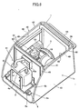
- the engine generator has a structure that an engine 2, a generator 3, a muffler 4, and a cooling fan 5 are disposed on a base 8, and also they are included within a housing 1 made of synthetic resin.
- the engine generator has the base 8, a side plate 39, a partition plate 40 and a tank bracket (beam member) 41 within the housing 1, so that an inner structure of the housing can become sturdy and rigid, and be divided into two rooms by the partition plate 40.
- the engine 2 and the muffler 4 are arranged in the different room each other.
- the housing 1 is formed with a double wall structure so as to improve a sound insulation performance. Thus, it can be accomplished to lower the noise caused by the device.
- the housing 1 is made of a synthetic resin with high heat resistance such as, for example, a polypropylene, which is mounted above the base 8.
- the inside of the housing 1 includes the engine 2 and the muffler 4 becoming hot. Therefore, as it is necessary to further improve the heat resistance, the housing 1 may be made by blow forming.
- a material and a manufacturing method according to the present invention are not limited to the above mentioned means.
- the housing 1 is constructed by three parts, namely a side cover 42, a main cover 43, and a door cover 44. These covers 42-44 form an upper wall 1a and side walls 1b-1e of the engine generator.
- the whole device results in a substantially box-like shape of six bodies.
- the side cover 42 is integrally formed with the base 8 and the side walls 1b, 1c adjacent to each other of the all four side walls 1b-1e.
- This side cover 42 including the base 8 forms three surfaces of the engine generator, namely a basic outer face structure thereof.
- the both main cover 43 and door cover 44 are attached with the side cover 42 including the base 8, thereby completely forming the whole outer body of the engine generator.
- a connection between the side cover 42 and base 8 may be carried out by a connecting member such as a screw, or by insertion forming of the base 8.
- a bottom wall of the housing 1 may be formed on a side of a lower surface of the base 8, and thereon the base 8 may be mounted.
- the base 8 may be substituted with the bottom wall of the housing 8, the base 8 may be omitted.
- the main cover 43 is formed by integrally constructing the upper wall 1a with the side wall Id of the side walls. This main cover 43 is detachably attached upon the side cover 42. While the main cover 43 is always fixed therewith in a normal use, it is removed when the inside of the device is inspected and/or repaired like an overhaul work.
- a fuel tank 45, a top portion of the engine 2, and the muffler 4 are exposed. Under this situation, the maintenance work of the engine 2 and the muffler 4 can be carried out.
- the fuel tank 45 is further removed, the whole of engine 2 and generator 3 and the other members are exposed, so that the maintenance work of the engine 2 and the generator 3 can be easily carried out.
- the side cover 42 is removed when carrying out an overhaul work, while the door cover 44 is removable for a daily inspection. Therefore, the door cover 44 is formed so as to be easily detachable with the side cover 42 and the main cover 43.
- Figs.5 and 6 show the engine generator attached with the door cover 44, of course, the overhaul work may be carried out through removing the door cover 44 also.
- each cover 42-44 is not only to cover each surface of six bodies, but also to allow the daily inspection and overhaul work thereof to be easily carried out. That is to say, it is sufficient for the maintenance work to remove the door cover 44 at a stage of the daily inspection, and the main cover 43 at a stage of the overhaul work. Consequently, extra components can be eliminated, so that component cost and the number of manufacturing steps can be reduced. Furthermore, it is sufficient to remove just a cover needed for the inspection and repair when inspecting it also, thereby improving the workability of inspection.
- covers 42-44 are formed with a hollow structure by blow forming. That is, these covers 42-44 are constructed by an outer wall 46 and an inner wall 48, respectively.
- the outer wall 46 forms an exterior of the engine generator, and a designed outside appearance.
- the inner wall 48 forms a device including room 47 for including the engine 2 and the generator 3.
- the covers 42-44 enclosing the engine 2 has a hollow space 49 between the outer and inner walls, which is an air layer, the improvement of sound insulation performance is obtained.
- a foaming material such as urethane
- the housing 1 is provided with the side plate 39 and the partition plate 40 on the base 8, and the tank bracket 41 is extended across between the side plate 39 and the partition plate 40.
- the device including room 47 within the housing 1 is divided into two rooms of the engine room 50 and the muffler room 51 by the partition plate 40.
- the base 8 is a flat plate made from metal, on which a bracket 6b for supporting the engine 2, a battery 52 and an inverter unit 53 are disposed. Furthermore, on the underside of the base 8, casters are attached.
- the side plate 39 is a wall member made from a sheet metal, and extends along a rear end of the housing 1, a lower end of which is fixed onto the base 8.
- An upper portion of the slide plate 8 has a handle 55 extending backward from a rear end of the housing 1.
- the partition plate 40 is also a wall member made from a sheet metal as well as the side plate 39, and stands between the engine 2 and the muffler 4 within the housing 1. A lower end of the partition plate 40 is fixed onto the base 8 as well as the side plate 39.
- the partition plate 40 is provided with an opening 40a at a central upper portion in the width direction, through which an exhaust pipe 56 is passed for connecting the engine 2 with the muffler 4.
- An upper portion of the side plate 39 and the partition plate 40 is further provided with a pair of tank brackets 41 which are formed by an angle steel made from metal, and connect the both upper ends of the side plate 39 and the partition plate 40 at the opposite ends, respectively, and the fuel tank 45 is mounted thereon.
- the housing 1 of the engine generator according to the present invention is divided into two rooms, namely the engine room 50 and the muffler room 51 by the partition plate 40.
- the partition plate 40 At the rear side of the partition plate 40 is formed the engine room 50 which is surrounded by the base 8, the side plate 39, the partition plate 40 and the tank bracket 41.
- the muffler room 50 which is surrounded by the base 8, the partition plate 40, the side cover 42 and the main cover 43.
- a side cover 42 with double walls and the side plate 39 are disposed at the rear side of the housing 1.
- triple walls comprising the outer wall 46, the inner wall 48, and the side plate 39 are formed at the rear side of the housing 1. Therefore, the sound insulation performance of the rear side of the housing 1 is improved, thereby the engine generator becomes more calm.
- a side face thereof without the side plate 39 also is formed by the side cover 42 with the double walls, the sound insulation performance of which also is improved, if compared with that having a side cover formed from a single plate.
- the partition plate 40 and the main cover 43 forms a triple walls structure, wherein the sound insulation performance is improved.
- the engine generator according to the present invention discloses the engine 2 at a substantially central position of the whole device so as to evenly insulate the noise of engine. Therefore, not only the working sound itself but also unevenness of the working sound in the direction of the arrangement of the device is reduced, so that an advantageous engine generator can be supplied.
- the engine room 50 is constructed by cube type frames comprising the base 8, the side plate 39, the partition plate 40 and the tank bracket 41 when viewed from a side direction thereof.
- the engine room 50 has a higher sound insulation performance caused by the side plate 39 and the partition plate 40, while it is constructed in a tough structure owing to the disposition of the tank bracket 41.
- the housing 1 is made of a synthetic resin, the mounting strength of the engine generator is ensured, so that not only the sound insulation performance but also vibration isolation performance and durability thereof are improved.
- the engine 2 is a all-purpose diesel engine, and a rotation of the crankshaft (not shown) thereof drives the generator 3 to generate an electric power.
- the generator 3 is a multipolar generator of an outer rotor type, which is arranged at the left side of the engine 2 in Fig.1.
- exhaust gas discharged from the engine 2 is transmitted to the muffler 4 which is arranged at the right side of the engine 2 in Fig.1, and then reduction of exhaust sound is conducted therein, and lastly is discharged from a exhaust port 4a to the outside of the device.
- the vibration isolation supporting portion 6 is formed by a vibration isolation supporting plate 6a, a bracket 6b mounted on the base 8, and a vibration isolation member 6c.
- the vibration isolation supporting plate 6a is attached to a lower surface of the both side ends of an oil pan (not shown) provided in the engine 2, and the vibration isolation member 6c is arranged between the vibration isolation supporting plate 6a and the bracket 6b.
- the vibration isolation member 6c is made of rubber, synthetic resin, or the like, and thus prevents a vibration of the engine 2 during the operation from being transmitted to the base 8.
- this vibration isolation supporting member 6 supports the engine 2, so that an attenuation of the engine vibration can be accomplished, thereby leading the calmness of the device.
Landscapes
- Engineering & Computer Science (AREA)
- Chemical & Material Sciences (AREA)
- Combustion & Propulsion (AREA)
- Mechanical Engineering (AREA)
- General Engineering & Computer Science (AREA)
- Motor Or Generator Frames (AREA)
- Exhaust Silencers (AREA)
Claims (6)
- Motorgenerator mit einem Motor und einem Generator, der angetrieben wird durch den Motor, auf einer Basis, und einem Gehäuse, beinhaltend eine obere Oberfläche und vier Seitenwände zum Aufnehmen des Motors und des Generators, wobei das Gehäuse aufweist:eine Seitenabdeckung zum eingliedernden Bilden der Basis mit zwei angrenzenden Oberflächen der vier Seitenwände;eine Hauptabdeckung zum eingliedernden Bilden der oberen Oberfläche mit einer anderen Oberfläche der vier Seitenwände; undeine Türabdeckung, gebildet mittels einer verbleibenden Oberfläche von sämtlichen Seitenwänden.
- Motorgenerator nach Anspruch 1, wobei die Hauptabdeckung für eine Instandsetzungsarbeit verwendet wird.
- Motorgenerator nach Anspruch 1, wobei die Türabdeckung verwendet wird als eine Zugangstür für eine tägliche Inspektion.
- Motorgenerator nach Anspruch 1, weiterhin aufweisend:eine äußere Wand zum Bilden eines Äußeren des Motorgenerators;eine innere Wand zum Einschließen des Motors und eines mit dem Motor verbundenen Auspufftopfes/Schalldämpfers; undwobei das Äußere des Motorgenerators eine Doppelwandstruktur aufweist, die gebildet wird durch die äußere Wand und die innere Wand.
- Motorgenerator nach Anspruch 4, wobei das Gehäuse gebildet wird durch Blasformen eines synthetischen Harzmaterials.
- Motorgenerator nach Anspruch 4, weiterhin aufweisend in der Doppelwandstruktur eingefülltes Schaummaterial.
Applications Claiming Priority (5)
| Application Number | Priority Date | Filing Date | Title |
|---|---|---|---|
| JP2000113699 | 2000-04-14 | ||
| JP2000113699A JP2001295663A (ja) | 2000-04-14 | 2000-04-14 | エンジン発電機 |
| JP2000113700 | 2000-04-14 | ||
| JP2000113700A JP2001295656A (ja) | 2000-04-14 | 2000-04-14 | エンジン発電機 |
| EP01303492A EP1146212B1 (de) | 2000-04-14 | 2001-04-17 | Motorgenerator |
Related Parent Applications (1)
| Application Number | Title | Priority Date | Filing Date |
|---|---|---|---|
| EP01303492A Division EP1146212B1 (de) | 2000-04-14 | 2001-04-17 | Motorgenerator |
Publications (2)
| Publication Number | Publication Date |
|---|---|
| EP1520967A1 EP1520967A1 (de) | 2005-04-06 |
| EP1520967B1 true EP1520967B1 (de) | 2006-12-20 |
Family
ID=26590150
Family Applications (2)
| Application Number | Title | Priority Date | Filing Date |
|---|---|---|---|
| EP01303492A Expired - Lifetime EP1146212B1 (de) | 2000-04-14 | 2001-04-17 | Motorgenerator |
| EP04078504A Expired - Lifetime EP1520967B1 (de) | 2000-04-14 | 2001-04-17 | Motorgenerator |
Family Applications Before (1)
| Application Number | Title | Priority Date | Filing Date |
|---|---|---|---|
| EP01303492A Expired - Lifetime EP1146212B1 (de) | 2000-04-14 | 2001-04-17 | Motorgenerator |
Country Status (3)
| Country | Link |
|---|---|
| US (1) | US6492740B2 (de) |
| EP (2) | EP1146212B1 (de) |
| DE (2) | DE60125427T2 (de) |
Families Citing this family (21)
| Publication number | Priority date | Publication date | Assignee | Title |
|---|---|---|---|---|
| JP3955455B2 (ja) * | 2001-10-11 | 2007-08-08 | 富士重工業株式会社 | 防音型エンジン発電機 |
| US20040168654A1 (en) * | 2003-02-28 | 2004-09-02 | Radtke David E. | Spatial relationship of components in engine-driven generator |
| US6952056B2 (en) * | 2003-08-06 | 2005-10-04 | Briggs & Stratton Power Products Group, Llc | Generator including vertically shafted engine |
| US7245030B2 (en) * | 2003-12-11 | 2007-07-17 | Siemens Power Generation, Inc. | Integrated generator and transformer and associated methods |
| JP4237069B2 (ja) * | 2004-01-19 | 2009-03-11 | デンヨー株式会社 | エンジン駆動作業機 |
| US7023101B2 (en) * | 2004-03-29 | 2006-04-04 | Wen-Chang Wang | Air cooling generator |
| US7314397B2 (en) | 2005-05-13 | 2008-01-01 | Briggs & Stratton Corporation | Standby generator |
| CA116632S (en) * | 2006-01-11 | 2008-01-16 | Shinko Electric Co Ltd | Hydraulic generator |
| CA116631S (en) * | 2006-01-11 | 2008-01-16 | Shinko Electric Co Ltd | Hydraulic generator |
| US7795745B2 (en) * | 2006-11-22 | 2010-09-14 | Girtz Industries | Fuel tank for a power generator set |
| JP4974155B2 (ja) * | 2007-04-02 | 2012-07-11 | ヤマハモーターパワープロダクツ株式会社 | 遮音型エンジン発電機 |
| US20090323256A1 (en) | 2008-06-25 | 2009-12-31 | Errera Michael R | Interface for system for generating electric power |
| JP4918528B2 (ja) * | 2008-06-27 | 2012-04-18 | 本田技研工業株式会社 | エンジン駆動発電機 |
| CN101392683A (zh) * | 2008-10-16 | 2009-03-25 | 无锡开普动力有限公司 | 固定式直流充电发电机 |
| CN101440745B (zh) * | 2008-12-12 | 2011-02-02 | 无锡开普动力有限公司 | 发动机发电机机组 |
| GB2504474B (en) | 2012-07-27 | 2015-08-05 | Caterpillar Ni Ltd | Base for a generator |
| US8960708B2 (en) * | 2012-11-30 | 2015-02-24 | Kohler Co. | Enclosure guide system for a towable generator |
| EP3006346B1 (de) * | 2014-10-10 | 2016-08-24 | Illinois Tool Works Inc. | Mobile Bodenversorgungseinheit mit verbessertem Gehaeusekonzept |
| US10344659B2 (en) * | 2014-12-04 | 2019-07-09 | Cummins Power Generation Ip, Inc. | Auxiliary diesel exhaust fluid systems |
| EP3397862A1 (de) * | 2016-03-03 | 2018-11-07 | Briggs & Stratton Corporation | Wechselgenerator |
| DE102016104807A1 (de) * | 2016-03-15 | 2017-09-21 | Steyr Motors Gmbh | Stromerzeugungsaggregat für mobile Anwendungen |
Family Cites Families (15)
| Publication number | Priority date | Publication date | Assignee | Title |
|---|---|---|---|---|
| US3805082A (en) * | 1970-01-22 | 1974-04-16 | J Murray | Portable power accessory with water bath for noise suppression |
| JPS58197418A (ja) * | 1982-05-12 | 1983-11-17 | Fuji Heavy Ind Ltd | 防音型エンジン駆動ゼネレータ |
| JPH0128270Y2 (de) * | 1984-10-09 | 1989-08-29 | ||
| US4647835A (en) * | 1984-12-19 | 1987-03-03 | Kawasaki Jukogyo Kabushiki Kaisha | Portable generator |
| US4907546A (en) * | 1987-12-02 | 1990-03-13 | Kubota Ltd. | Air-cooled type cooling system for engine working machine assembly |
| US5212952A (en) * | 1988-07-09 | 1993-05-25 | Yamaha Hatsudoki Kabushiki Kaisha | Compact power supply and lubricant affording device therefor |
| FR2659113B1 (fr) * | 1990-03-02 | 1992-06-12 | Lombardini France | Ensemble portatif associant un moteur thermique et une machine, par exemple groupe electrogene. |
| US5125378A (en) * | 1990-10-29 | 1992-06-30 | Westerbeke Corporation | Cooling system for an enclosed heat source |
| BE1008959A4 (fr) * | 1994-12-19 | 1996-10-01 | Solvay | Polymere du propylene, procede pour son obtention et utilisation. |
| US5850061A (en) * | 1996-07-10 | 1998-12-15 | Kohler Co. | Generator sound shield |
| JP3800372B2 (ja) | 1997-07-24 | 2006-07-26 | 本田技研工業株式会社 | エンジン発電機 |
| JPH11136879A (ja) | 1997-10-29 | 1999-05-21 | Yuasa Corp | 太陽光発電装置 |
| JP3347044B2 (ja) * | 1998-01-19 | 2002-11-20 | 本田技研工業株式会社 | 携帯用エンジン作業機 |
| US5899174A (en) * | 1998-02-06 | 1999-05-04 | Anderson; Wayne A. | Enclosed engine generator set |
| US6084313A (en) * | 1998-08-13 | 2000-07-04 | Coleman Powermate, Inc. | Generator system with vertically shafted engine |
-
2001
- 2001-04-16 US US09/835,997 patent/US6492740B2/en not_active Expired - Fee Related
- 2001-04-17 EP EP01303492A patent/EP1146212B1/de not_active Expired - Lifetime
- 2001-04-17 DE DE60125427T patent/DE60125427T2/de not_active Expired - Fee Related
- 2001-04-17 DE DE60112158T patent/DE60112158T2/de not_active Expired - Fee Related
- 2001-04-17 EP EP04078504A patent/EP1520967B1/de not_active Expired - Lifetime
Also Published As
| Publication number | Publication date |
|---|---|
| EP1146212A2 (de) | 2001-10-17 |
| EP1146212A3 (de) | 2002-10-23 |
| US20010029733A1 (en) | 2001-10-18 |
| DE60112158D1 (de) | 2005-09-01 |
| DE60112158T2 (de) | 2006-04-20 |
| DE60125427T2 (de) | 2007-10-11 |
| EP1520967A1 (de) | 2005-04-06 |
| DE60125427D1 (de) | 2007-02-01 |
| EP1146212B1 (de) | 2005-07-27 |
| US6492740B2 (en) | 2002-12-10 |
Similar Documents
| Publication | Publication Date | Title |
|---|---|---|
| EP1520967B1 (de) | Motorgenerator | |
| JP3916393B2 (ja) | エンジン発電機 | |
| JP3815703B2 (ja) | エンジン発電機 | |
| CN1328491C (zh) | 发动机驱动装置 | |
| US6039009A (en) | Engine-operated generator | |
| EP1296039B1 (de) | Motorgenerator | |
| CN101280716B (zh) | 隔音型发动机式发电机 | |
| JP4052823B2 (ja) | エンジン発電機 | |
| JP2003120308A (ja) | 防音型エンジン発電機 | |
| US6095099A (en) | Engine operated working machine | |
| JP3753529B2 (ja) | エンジン発電機 | |
| JP2002238214A (ja) | エンジン発電機 | |
| JP3800374B2 (ja) | エンジン発電機 | |
| JPH10196392A (ja) | エンジン発電機の排気構造 | |
| JP4327558B2 (ja) | エンジン発電機 | |
| JPH02188622A (ja) | 防音型エンジン作業機 | |
| JP6773921B2 (ja) | エンジン装置 | |
| JP2001295663A (ja) | エンジン発電機 | |
| JP2001295656A (ja) | エンジン発電機 | |
| JP2003074362A (ja) | エンジン発電機 | |
| JP2006112413A (ja) | エンジン駆動作業機 | |
| JPH0555693B2 (de) | ||
| JPH0133785Y2 (de) | ||
| JPH0218290Y2 (de) | ||
| JP3728043B2 (ja) | エンジン駆動熱ポンプ装置の室外機ユニット |
Legal Events
| Date | Code | Title | Description |
|---|---|---|---|
| PUAI | Public reference made under article 153(3) epc to a published international application that has entered the european phase |
Free format text: ORIGINAL CODE: 0009012 |
|
| 17P | Request for examination filed |
Effective date: 20041213 |
|
| AC | Divisional application: reference to earlier application |
Ref document number: 1146212 Country of ref document: EP Kind code of ref document: P |
|
| AK | Designated contracting states |
Kind code of ref document: A1 Designated state(s): DE GB |
|
| AKX | Designation fees paid |
Designated state(s): DE GB |
|
| GRAP | Despatch of communication of intention to grant a patent |
Free format text: ORIGINAL CODE: EPIDOSNIGR1 |
|
| GRAS | Grant fee paid |
Free format text: ORIGINAL CODE: EPIDOSNIGR3 |
|
| GRAA | (expected) grant |
Free format text: ORIGINAL CODE: 0009210 |
|
| AC | Divisional application: reference to earlier application |
Ref document number: 1146212 Country of ref document: EP Kind code of ref document: P |
|
| AK | Designated contracting states |
Kind code of ref document: B1 Designated state(s): DE GB |
|
| REG | Reference to a national code |
Ref country code: GB Ref legal event code: FG4D |
|
| REF | Corresponds to: |
Ref document number: 60125427 Country of ref document: DE Date of ref document: 20070201 Kind code of ref document: P |
|
| PGFP | Annual fee paid to national office [announced via postgrant information from national office to epo] |
Ref country code: DE Payment date: 20070430 Year of fee payment: 7 |
|
| PLBE | No opposition filed within time limit |
Free format text: ORIGINAL CODE: 0009261 |
|
| STAA | Information on the status of an ep patent application or granted ep patent |
Free format text: STATUS: NO OPPOSITION FILED WITHIN TIME LIMIT |
|
| PGFP | Annual fee paid to national office [announced via postgrant information from national office to epo] |
Ref country code: GB Payment date: 20070404 Year of fee payment: 7 |
|
| 26N | No opposition filed |
Effective date: 20070921 |
|
| GBPC | Gb: european patent ceased through non-payment of renewal fee |
Effective date: 20080417 |
|
| PG25 | Lapsed in a contracting state [announced via postgrant information from national office to epo] |
Ref country code: DE Free format text: LAPSE BECAUSE OF NON-PAYMENT OF DUE FEES Effective date: 20081101 |
|
| PG25 | Lapsed in a contracting state [announced via postgrant information from national office to epo] |
Ref country code: GB Free format text: LAPSE BECAUSE OF NON-PAYMENT OF DUE FEES Effective date: 20080417 |