EP1520756B1 - Gurtumlenkeinrichtung für einen Sicherheitsgurt eines Kraftfahrzeugs - Google Patents
Gurtumlenkeinrichtung für einen Sicherheitsgurt eines Kraftfahrzeugs Download PDFInfo
- Publication number
- EP1520756B1 EP1520756B1 EP04090364A EP04090364A EP1520756B1 EP 1520756 B1 EP1520756 B1 EP 1520756B1 EP 04090364 A EP04090364 A EP 04090364A EP 04090364 A EP04090364 A EP 04090364A EP 1520756 B1 EP1520756 B1 EP 1520756B1
- Authority
- EP
- European Patent Office
- Prior art keywords
- belt
- holding body
- deflecting
- deflecting device
- edge
- Prior art date
- Legal status (The legal status is an assumption and is not a legal conclusion. Google has not performed a legal analysis and makes no representation as to the accuracy of the status listed.)
- Expired - Lifetime
Links
- 229910052751 metal Inorganic materials 0.000 claims description 16
- 239000002184 metal Substances 0.000 claims description 16
- 229910000831 Steel Inorganic materials 0.000 claims description 11
- 239000010959 steel Substances 0.000 claims description 11
- 230000001154 acute effect Effects 0.000 claims description 7
- 238000005452 bending Methods 0.000 claims description 5
- 238000004519 manufacturing process Methods 0.000 claims description 5
- 229910052782 aluminium Inorganic materials 0.000 claims description 3
- XAGFODPZIPBFFR-UHFFFAOYSA-N aluminium Chemical compound [Al] XAGFODPZIPBFFR-UHFFFAOYSA-N 0.000 claims description 3
- 238000007493 shaping process Methods 0.000 claims 3
- 238000009434 installation Methods 0.000 claims 2
- 239000004411 aluminium Substances 0.000 claims 1
- 238000010521 absorption reaction Methods 0.000 description 4
- 238000003780 insertion Methods 0.000 description 4
- 230000037431 insertion Effects 0.000 description 4
- 238000004080 punching Methods 0.000 description 4
- 238000010276 construction Methods 0.000 description 3
- 230000006378 damage Effects 0.000 description 2
- 238000000034 method Methods 0.000 description 2
- 230000001133 acceleration Effects 0.000 description 1
- 238000005266 casting Methods 0.000 description 1
- 238000002347 injection Methods 0.000 description 1
- 239000007924 injection Substances 0.000 description 1
- 238000001746 injection moulding Methods 0.000 description 1
- 238000000465 moulding Methods 0.000 description 1
- 230000000452 restraining effect Effects 0.000 description 1
Images
Classifications
-
- B—PERFORMING OPERATIONS; TRANSPORTING
- B60—VEHICLES IN GENERAL
- B60R—VEHICLES, VEHICLE FITTINGS, OR VEHICLE PARTS, NOT OTHERWISE PROVIDED FOR
- B60R22/00—Safety belts or body harnesses in vehicles
- B60R22/18—Anchoring devices
-
- B—PERFORMING OPERATIONS; TRANSPORTING
- B60—VEHICLES IN GENERAL
- B60R—VEHICLES, VEHICLE FITTINGS, OR VEHICLE PARTS, NOT OTHERWISE PROVIDED FOR
- B60R22/00—Safety belts or body harnesses in vehicles
- B60R22/18—Anchoring devices
- B60R2022/1818—Belt guides
- B60R2022/1843—Belt guides comprising an elongated sleeve
Definitions
- the invention relates to a Gurtumlenk noticed for a safety belt of a motor vehicle.
- German Offenlegungsschrift DE 101 03 319 A1 describes a belt deflection device with an energy absorption unit. If, in the event of a vehicle accident, the seatbelt is deflected by the vehicle occupant, a considerable pulling force is exerted on the deflecting device.
- the energy absorption unit is configured such that it allows the seat belt to give way; This is done concretely in such a way that a deflecting element of the Gurtumlenk Vietnamese is displaced or moved under deformation of the deflecting holding elements such that it comes to a "belt extension" for the vehicle occupants.
- the previously known Gurtumlenk issued is constructed in several parts.
- US Pat. No. 5,139,282 describes a belt deflection device with a deflection element, which is fastened pivotably or rotatably by means of a screw to the vehicle body.
- the deflection element is associated with a spring element which exerts on the seat belt a predetermined biasing force, which presses the seat belt against the vehicle occupant. Due to the pivotable mounting of the deflecting element on the vehicle body, the deflecting element can rotate or pivot during a movement of the vehicle occupant, so that the position of the seat belt may change relative to the vehicle occupant. In the case of a vehicle accident, this pivoting of the deflecting element may be disadvantageous, because it can lead to jamming or twisting of the seat belt on the deflection on reaching a critical pivot angle. The function of the seat belt can be affected.
- the invention has for its object to provide a Gurtumlenk noticed for a safety belt of a motor vehicle, which has a simple and therefore inexpensive construction and at the same time ensures a high level of safety for the vehicle occupants in the event of a vehicle accident.
- a Gurtumlenk beautiful is provided for a safety belt according to the invention, in which a one-piece holding body is present.
- the one-piece holding body has at least one holding point on which a deflecting element is held; the deflection element forms a deflection axis about which the seat belt of the motor vehicle is deflected.
- the holding body according to the invention also formed such that it forms a Gurtumlenkkante to which the seat belt of the motor vehicle another time, so in addition, is deflected.
- the deflecting edge of the holding body is at an acute angle to the deflection axis of the deflecting element.
- the holding body according to the invention also has at least one attachment point, which allows a rigid mounting of the holding body to the body of the motor vehicle.
- Gurtumlenk ensures a reliable "functioning" of the seat belt even in the event of a vehicle accident; in particular a jamming or twisting or “turning over" of the seat belt on the deflecting element of the Gurtumlenk Republic can not occur.
- This is inventively achieved in that the deflecting element is held by the one-piece holding body, which is itself rigidly mounted on the body of the motor vehicle.
- a pivoting or a rotation of the deflecting element relative to the body can in the inventive Gurtumlenk issued - unlike, for example, the pivotable Gurtumlenk achieved according to the aforementioned US Patent - thus not occur.
- Gurtumlenk Another significant advantage of Gurtumlenk picked invention is its cost-effective structure, since the "central" holding body Gurtumlenk issued that according to the invention provides all the essential functions of Gurtumlenk Republic - is integrally formed. Due to the one-piece design of the holding body additional mounting steps - with respect to the holding body - superfluous, whereby the overall assembly of Gurtumlenk Republic is kept simple and inexpensive.
- Gurtumlenk for deflecting the seat belt has two separate “deflection", namely on the one hand the deflection and on the other hand, the deflection. Due to the arrangement of the deflecting edge at an acute angle to the deflection axis of the deflecting element is always ensured that despite the rigid mounting of the holding body to the body and thus despite - in contrast to the said US Patent - not "trackable" orientation of the deflection axis of the deflecting always an optimal alignment of the seat belt to the vehicle occupant is present.
- the one-piece holding body of Gurtumlenk attach to the body of the motor vehicle when the or the attachment points are formed by eyelets, hooks or flanges.
- the one-piece holding body has at least two spaced apart or "spaced” arranged attachment points; the attachment points are formed on the holding body in such a way that the remaining area of the holding body-for example, the center area between the attachment points-at least partially has a predetermined distance to the body after assembly of the holding body on the body.
- a kind of "bridge” is thus formed by the holding body by the at least two spaced attachment points.
- the middle bridge area which has a distance from the body, thus forms a "deformation area” which can absorb energy in motor vehicle Y direction. If the Gurtumlenk issued mounted, for example, in the area of the B-pillar of a motor vehicle, it is usually located in the shoulder or head height of the motor vehicle occupant.
- the described "bridge construction" is provided which allows yielding of the central region of the one-piece holding body, since the central region or middle bridge region can be pressed onto the body while deforming the holding body. By this deformation kinetic energy is "converted", so that the impact of the head of the vehicle occupant is at least somewhat damped.
- the middle region between the fastening points is preferably at least slightly deformable in the Y direction or in the body direction.
- the Gurtumlenkkante formed by the shape of the holding body is preferably rounded at least in the cooperating with the seat belt area, so that the friction between Gurtumlenkkante and the seat belt is minimized.
- the rounding of the deflection can be done for example by "flanging” or direct “molding".
- the Gurtumlenkkante can be formed by a longitudinal edge of an opening slot or a belt exit slot in the holding body.
- This belt outlet slit should - for the reasons mentioned - at least be crimped in its cooperating with the safety belt area to keep the friction between the seat belt and Gurtumlenkkante as low as possible.
- the acute angle between the deflection axis of the deflecting element and the Gurtumlenkkante is in the range between 20 ° and 70 °, since with such an angle selection a particularly good alignment of the seat belt is ensured relative to the vehicle occupant.
- Particularly preferred is an angular range between 35 ° and 55 °, since such an angular range in most motor vehicle models ensures an optimal relative position or orientation of the seat belt relative to the vehicle occupant.
- the acute angle may be, for example, about 45 °.
- the deflecting element can be particularly simple and thus advantageously formed, for example, by a rotatably mounted deflection roller which is fastened by means of a pin on the integrally formed holding body.
- the pin may be, for example, a metal pin, in particular a steel pin.
- the pin is held on at least two holding points formed on the holding body.
- the pin can also be rotatably mounted, for example, in the breakpoints.
- the deflection element can also be formed by a deflection bar, which is integrally formed on the holding body.
- the deflecting element can also be realized by an integrally formed on the holding body, further deflection.
- a disadvantage is a deflection bar or a further deflection edge in comparison to a rotatably mounted Umlenkrolle, however, in the respect that greater frictional forces are exerted on the seat belt, so that the ease of use is slightly lower than in the case of a rotatably mounted pulley, in which due to the rotatable bearing only a small friction occurs and thus a particularly easy deflection or Moving the seat belt by the vehicle occupants is possible.
- the holding body additionally has a Gurtein manufacturedschlitz, which is preferably arranged parallel to the deflection axis of the deflection.
- the safety belt is then inserted through the Gurtein technologicalschlitz in the region of the holding body and passed from Gurtein technologicalschlitz to the deflection element; from the deflecting the seat belt is deflected in the direction of Gurtumlenkkante.
- the seat belt is subsequently deflected once again in the direction of the vehicle occupant by the belt deflection edge, so that the safety belt leaves the region of the holding body again.
- the one-piece holding body is formed by a stamped and bent part, for example by a stamped and bent part made of sheet metal. By punching and bending, the one-piece holding body can be particularly simple and therefore inexpensive to produce.
- the above-explained belt exit slot is preferably formed by punching out of the stamped and bent part or from the sheet metal part.
- the attachment points are then preferably formed by bending edge regions, in the mounting direction towards the vehicle body.
- the Gurtein manufacturedschlitz is preferably stamped into the one-piece holding body.
- a stamped and bent part of the one-piece holding body may also be formed by a plastic injection molded part or by an aluminum casting.
- the invention is also based on the object of specifying a simple and cost-effective method for producing a Gurtumlenk issued for a safety belt of a motor vehicle, which is a simple and therefore inexpensive construction and at the same time ensures a high degree of safety for the vehicle occupant even in the event of a vehicle accident.
- a method for producing a Gurtumlenk beautiful in which a one-piece holding body is formed by a sheet metal part in which in the middle region of the sheet metal part, a belt exit slot is punched and / or attachment points are formed by bending edge portions of the sheet metal part and / or a belt insertion slot is punched in the one-piece holding body.
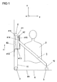
- FIG. 1 shows a safety belt device with a safety belt 1 for a vehicle occupant 2.
- the belt 1 is rolled up with its one belt end 11 on a belt reel 3.
- the belt reel 3 is firmly connected to the body 8 in the floor area 81 of the vehicle body 8.
- the belt reel 3 has a torque-generating mechanism that is biased in Gurtaufwickelides and tightens the seat belt 1.
- the belt reel 3 also has a Abwickelsperran let which locks the seat belt 1 against the force of the torque-generating mechanism in attempted, quick withdrawal of the seat belt 1 and / or accidental acceleration of the unwinding of the seat belt.
- the seat belt 1 extends from its end 11, which is connected to the belt reel 3, via a belt deflection device 4 to a belt lock 5, to which the other end 12 of the safety belt is detachably fixed or held.
- the Gurtumlenk prepared 4 has an integral holding body 41 which is rigidly secured to an upper attachment point 411 and at a lower attachment point 412 in the region of the B-pillar 82 on the vehicle body 8.
- the attachment height of the Gurtumlenk Vietnamese 4 or the one-piece holding body 41 is thereby granted such that the seat belt 1 is deflected approximately at shoulder height of the vehicle occupant 2.
- the seat belt 1 extends upwardly from the one end 11 thereof along the vehicle Z direction along the B pillar 82 and enters the belt turning device 4 through a belt insertion slot 413.
- an upper deflecting element 42 of the Gurtumlenk Vietnamese 4 the seat belt 1 is deflected such that it now runs counter to the vehicle Z-direction again almost vertically downwards.
- a belt exit slot 414 of the one-piece holding body 41 the seat belt 1 leaves the Gurtumlenk issued 4 and is guided over the shoulder and chest area of the vehicle occupant 2 to the buckle 5.
- the belt exit slot 414 is configured in such a way that the seat belt 1 is tilted by approximately 20 ° to 70 ° in the chest region of the vehicle occupant 2 so that the seat belt 1 rests in an optimal position on the vehicle occupant 2.
- a center region 415 of the holding body 41 is arranged at a small distance from the B-pillar 81 of the vehicle body 8; This is achieved concretely by the two attachment points 411 and 412, which are attached to the holding body 41 such that the center region 415 has a predetermined distance ⁇ x to the B pillar 81.
- the distance ⁇ x between the center portion 415 and the vehicle B pillar 81 comes into play in the event of a vehicle accident. Namely, in the case of a vehicle accident, the head of the vehicle occupant 2 against the Gurtumlenk issued 4 or against the Thrown support body 41, the center region 415 of the holding body 41 may yield slightly, since it can be deformed in the direction of the vehicle B-pillar 82 due to the distance .DELTA.x. A fatal impact of the head of the vehicle occupant 2 on the Gurtumlenkeinrichung 4 can thus be prevented.
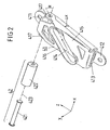
- the belt deflection device 4 according to FIG. 1 is shown in detail - in the unassembled state. It can be seen the holding body 41 with its upper attachment point 411 and with its lower attachment point 412.
- the two attachment points 411 and 412 are each formed by eyelets.
- one of the two attachment points or both can be illustrated by hooks or mounting flanges.
- the upper attachment point 411 may be formed by the eye shown in Figure 2, whereas the lower attachment point 412 is replaced by two attachment hooks.
- the distance ⁇ x between the center region 415 and the fastening surface of the holding body 41 formed by the two attachment points 411 and 412 on the B pillar 81 of the motor vehicle body 8 can be recognized.
- FIG. 2 also shows the belt insertion slot 413 and the belt exit slot 414, which are each made by punching into the holding body formed by a one-piece stamped and bent part made of sheet metal.
- the belt exit slot 414 has a rebounded or rounded edge, which forms a deflection edge 416 of the belt exit slot 414.
- FIG. 2 also shows the upper deflecting element 42, which is formed by a steel pin 421 and a deflection roller 422.
- the steel pin 421 is held along its deflection axis 423 at two holding points 417 of the holding body 41.
- the guide roller 422 is rotatably mounted on the steel pin 421, so that the guide roller 422 can rotate on the steel pin 421 very low friction.
- the deflection edge 416 of the belt exit slot 414 and the deflection axis 423 of the upper deflection element 42 form an angle ⁇ .
- the angle ⁇ may be in a range between 30 ° and 70 °, for example, in a range between 35 ° and 55 °. In the embodiment according to FIG. 2, the angle is approximately 45 °.
- Gurtein rawschlitz 413 and the deflection axis 423 are largely aligned parallel to each other.
- the holding body 41 is - as already explained - made in one piece; this means that the two attachment points 411 and 412, the two stop points 417, the belt insertion slot 413 and the belt exit slot 414 are integrally formed.
- the holding body 41 may be formed, for example, by punching and bending a sheet, for example a steel sheet. Alternatively, the holding body 41 may also be formed by injection molding of plastic or die-cast aluminum. In order to enable a simple and cost-effective production of the holding body, it is only advantageous if the holding body in one piece - as shown - is formed.
- the upper deflection element 42 is formed by the steel pin 421 and the deflection roller 422.
- the upper deflection element 42 can be formed by a deflection bar, by a deflecting sheet metal part or the like.
- the deflection bar or the deflecting sheet metal part are then preferably formed integrally on the holding body 41.
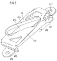
- the holding body 41 is shown according to the figure 2 again in the assembled state. It can be seen the guide roller 422, which is mounted on the steel pin 421. The steel pin 421 is fixed in the two holding points 417 of the holding body 41.
Landscapes
- Engineering & Computer Science (AREA)
- Mechanical Engineering (AREA)
- Automotive Seat Belt Assembly (AREA)
Applications Claiming Priority (2)
| Application Number | Priority Date | Filing Date | Title |
|---|---|---|---|
| DE10346172 | 2003-10-01 | ||
| DE10346172A DE10346172A1 (de) | 2003-10-01 | 2003-10-01 | Gurtumlenkeinrichtung für einen Sicherheitsgurt eines Kraftfahrzeugs |
Publications (3)
| Publication Number | Publication Date |
|---|---|
| EP1520756A2 EP1520756A2 (de) | 2005-04-06 |
| EP1520756A3 EP1520756A3 (de) | 2006-03-01 |
| EP1520756B1 true EP1520756B1 (de) | 2007-02-21 |
Family
ID=34306263
Family Applications (1)
| Application Number | Title | Priority Date | Filing Date |
|---|---|---|---|
| EP04090364A Expired - Lifetime EP1520756B1 (de) | 2003-10-01 | 2004-09-20 | Gurtumlenkeinrichtung für einen Sicherheitsgurt eines Kraftfahrzeugs |
Country Status (5)
| Country | Link |
|---|---|
| US (1) | US7322611B2 (zh) |
| EP (1) | EP1520756B1 (zh) |
| JP (1) | JP4854189B2 (zh) |
| CN (1) | CN100381305C (zh) |
| DE (2) | DE10346172A1 (zh) |
Families Citing this family (4)
| Publication number | Priority date | Publication date | Assignee | Title |
|---|---|---|---|---|
| JP2007050824A (ja) * | 2005-08-19 | 2007-03-01 | Takata Corp | シートベルト用ガイドアンカーおよびこれを備えたシートベルト装置 |
| DE102008012951B4 (de) | 2008-03-06 | 2009-10-29 | Takata-Petri Ag | Gurtumlenkvorrichtung |
| US20160311396A1 (en) * | 2015-04-24 | 2016-10-27 | GM Global Technology Operations LLC | Belt buckle anchor for thin seats |
| DE102015213487A1 (de) * | 2015-07-17 | 2017-01-19 | Bayerische Motoren Werke Aktiengesellschaft | Sicherheitsgurtvorrichtung für ein Kraftfahrzeug und Kraftfahrzeug mit einer solchen Sicherheitsgurtvorrichtung |
Family Cites Families (14)
| Publication number | Priority date | Publication date | Assignee | Title |
|---|---|---|---|---|
| DE2551329A1 (de) * | 1975-11-15 | 1977-05-18 | Daimler Benz Ag | Oberes, hoehenverschiebbar in einem karosseriehohlraum angeordnetes beschlagteil eines schultergurtes |
| GB1577951A (en) * | 1976-04-26 | 1980-10-29 | Coenen Benelux Bv | Safety belt |
| EP0018122B1 (en) * | 1979-04-03 | 1985-11-13 | Secretary of State for Transport in Her Britannic Majesty's Gov. of the United Kingdom of Great Britain and Northern Ireland | Strop securing means |
| JPS58101856A (ja) * | 1981-12-15 | 1983-06-17 | Nissan Motor Co Ltd | シ−トベルトスル− |
| JPS62453A (ja) * | 1985-06-27 | 1987-01-06 | Konishiroku Photo Ind Co Ltd | クロルフエニルヒドラジン系化合物を製造する方法 |
| JPH03184749A (ja) * | 1989-12-11 | 1991-08-12 | Fanuc Ltd | 回転体ならい制御装置 |
| US5139282A (en) * | 1991-05-06 | 1992-08-18 | General Motors Corporation | Shoulder belt comfort spring |
| US5599070A (en) * | 1995-12-12 | 1997-02-04 | Trw Vehicle Safety Systems Inc. | Seat and integral seat belt |
| US5722732A (en) * | 1996-08-26 | 1998-03-03 | General Motors Corporation | Shoulder belt retractor with headrest support |
| JPH11217057A (ja) * | 1998-02-02 | 1999-08-10 | Nippon Seiko Kk | シートベルト支持装置 |
| DE19915024B4 (de) | 1999-04-01 | 2013-04-25 | TAKATA Aktiengesellschaft | Sicherheitsgurtanordnung bei Fahrzeugen |
| DE10103319A1 (de) | 2001-01-25 | 2002-08-01 | Takata Europa Vehicle Safety T | Sicherheitsgurtvorrichtung |
| US7004503B2 (en) * | 2001-05-01 | 2006-02-28 | Takata-Petri (Ulm) Gmbh | Safety belt arrangement in vehicles |
| JP2003154922A (ja) * | 2001-11-19 | 2003-05-27 | Tokai Rika Co Ltd | プリテンショナ装置及びシートベルト装置 |
-
2003
- 2003-10-01 DE DE10346172A patent/DE10346172A1/de not_active Withdrawn
-
2004
- 2004-09-20 EP EP04090364A patent/EP1520756B1/de not_active Expired - Lifetime
- 2004-09-20 DE DE502004002942T patent/DE502004002942D1/de not_active Expired - Lifetime
- 2004-09-30 CN CNB2004100833562A patent/CN100381305C/zh not_active Expired - Fee Related
- 2004-09-30 JP JP2004286791A patent/JP4854189B2/ja not_active Expired - Fee Related
- 2004-10-01 US US10/954,950 patent/US7322611B2/en not_active Expired - Fee Related
Also Published As
| Publication number | Publication date |
|---|---|
| CN100381305C (zh) | 2008-04-16 |
| JP2005104463A (ja) | 2005-04-21 |
| DE502004002942D1 (de) | 2007-04-05 |
| EP1520756A2 (de) | 2005-04-06 |
| US7322611B2 (en) | 2008-01-29 |
| DE10346172A1 (de) | 2005-04-21 |
| JP4854189B2 (ja) | 2012-01-18 |
| EP1520756A3 (de) | 2006-03-01 |
| US20050104358A1 (en) | 2005-05-19 |
| CN1618668A (zh) | 2005-05-25 |
Similar Documents
| Publication | Publication Date | Title |
|---|---|---|
| EP2117885B1 (de) | Sicherheitsgurtanordnung für ein kraftfahrzeug | |
| EP0376320B1 (de) | Höhenverstellbarer Umlenkbeschlag für Sicherheitsgurte von Kraftfahrzeugen | |
| EP2651743B1 (de) | Lenksäule für ein kraftfahrzeug | |
| EP2133495B1 (de) | Kraftfahrzeugschloß | |
| EP2180807B1 (de) | Schlossumlenkeinrichtung | |
| EP3423313A1 (de) | Klappenscharnier für eine frontklappe eines fahrzeugs mit einer verschiebbaren lagerung eines hubaktuators | |
| DE102007046961A1 (de) | Energieabsorptions-Sitzverankerungs-Rückhaltesystem für Kinder-Sicherheitssitze | |
| DE202007017349U1 (de) | Einrast-Führungsschlaufenanordnung | |
| WO2002051669A1 (de) | Vorrichtung zur lagerung eines pedalhebels eines kraftfahrzeuges | |
| DE102013109931A1 (de) | Anordnung mit zumindest einem Federkörper und zumindest einem separat ausgebildeten Arretierteil | |
| DE102012219090A1 (de) | Sicherheitsgurt-Verschlussplattenanordnung | |
| EP2342406B1 (de) | HANDHABE FÜR EINE SCHLIEßEINRICHTUNG EINES KRAFTFAHRZEUGES | |
| DE102005009277B4 (de) | Halterung für eine Komponente | |
| EP1565357B1 (de) | Befestigungsanordnung für einen gurtaufroller | |
| EP2636827A2 (de) | Kraftfahrzeugschloss | |
| DE102017219014A1 (de) | Lenksäule für ein Kraftfahrzeug | |
| EP2244926B1 (de) | Lenksäule für ein kraftfahrzeug, mit einer lenkspindel und einer feststelleinrichtung | |
| EP1358094A1 (de) | Vorrichtung zur lagerung eines pedalhebels eines kraftfahrzeuges | |
| DE102008022813A1 (de) | Kindersitz | |
| EP1520756B1 (de) | Gurtumlenkeinrichtung für einen Sicherheitsgurt eines Kraftfahrzeugs | |
| EP2636826A2 (de) | Kraftfahrzeugschloss | |
| WO2013098323A1 (de) | Entriegelungssperrvorrichtung, aufbewahrungsfach mit entriegelungssperrvorrichtung, und verfahren zum beschleunigungsaktivierten sperren einer entriegelung eines aufbewahrungsfaches | |
| DE68905756T2 (de) | Handvorrichtung zur verstellung eines sicherheitsgurtels. | |
| DE102007007702A1 (de) | Sicherheitsgurtanordnung für ein Kraftfahrzeug | |
| DE102005053647B4 (de) | Befestigungsvorrichtung |
Legal Events
| Date | Code | Title | Description |
|---|---|---|---|
| PUAI | Public reference made under article 153(3) epc to a published international application that has entered the european phase |
Free format text: ORIGINAL CODE: 0009012 |
|
| AK | Designated contracting states |
Kind code of ref document: A2 Designated state(s): AT BE BG CH CY CZ DE DK EE ES FI FR GB GR HU IE IT LI LU MC NL PL PT RO SE SI SK TR |
|
| AX | Request for extension of the european patent |
Extension state: AL HR LT LV MK |
|
| PUAL | Search report despatched |
Free format text: ORIGINAL CODE: 0009013 |
|
| AK | Designated contracting states |
Kind code of ref document: A3 Designated state(s): AT BE BG CH CY CZ DE DK EE ES FI FR GB GR HU IE IT LI LU MC NL PL PT RO SE SI SK TR |
|
| AX | Request for extension of the european patent |
Extension state: AL HR LT LV MK |
|
| 17P | Request for examination filed |
Effective date: 20060509 |
|
| GRAP | Despatch of communication of intention to grant a patent |
Free format text: ORIGINAL CODE: EPIDOSNIGR1 |
|
| AKX | Designation fees paid |
Designated state(s): DE FR GB SE |
|
| RAP1 | Party data changed (applicant data changed or rights of an application transferred) |
Owner name: TAKATA - PETRI AG |
|
| GRAS | Grant fee paid |
Free format text: ORIGINAL CODE: EPIDOSNIGR3 |
|
| GRAA | (expected) grant |
Free format text: ORIGINAL CODE: 0009210 |
|
| AK | Designated contracting states |
Kind code of ref document: B1 Designated state(s): DE FR GB SE |
|
| REG | Reference to a national code |
Ref country code: GB Ref legal event code: FG4D Free format text: NOT ENGLISH |
|
| REF | Corresponds to: |
Ref document number: 502004002942 Country of ref document: DE Date of ref document: 20070405 Kind code of ref document: P |
|
| REG | Reference to a national code |
Ref country code: SE Ref legal event code: TRGR |
|
| GBT | Gb: translation of ep patent filed (gb section 77(6)(a)/1977) |
Effective date: 20070418 |
|
| ET | Fr: translation filed | ||
| PLBE | No opposition filed within time limit |
Free format text: ORIGINAL CODE: 0009261 |
|
| STAA | Information on the status of an ep patent application or granted ep patent |
Free format text: STATUS: NO OPPOSITION FILED WITHIN TIME LIMIT |
|
| 26N | No opposition filed |
Effective date: 20071122 |
|
| PGFP | Annual fee paid to national office [announced via postgrant information from national office to epo] |
Ref country code: GB Payment date: 20090916 Year of fee payment: 6 Ref country code: SE Payment date: 20090910 Year of fee payment: 6 |
|
| REG | Reference to a national code |
Ref country code: SE Ref legal event code: EUG |
|
| GBPC | Gb: european patent ceased through non-payment of renewal fee |
Effective date: 20100920 |
|
| PG25 | Lapsed in a contracting state [announced via postgrant information from national office to epo] |
Ref country code: GB Free format text: LAPSE BECAUSE OF NON-PAYMENT OF DUE FEES Effective date: 20100920 |
|
| REG | Reference to a national code |
Ref country code: DE Ref legal event code: R082 Ref document number: 502004002942 Country of ref document: DE Representative=s name: MAIKOWSKI & NINNEMANN PATENTANWAELTE, DE |
|
| PG25 | Lapsed in a contracting state [announced via postgrant information from national office to epo] |
Ref country code: SE Free format text: LAPSE BECAUSE OF NON-PAYMENT OF DUE FEES Effective date: 20100921 |
|
| REG | Reference to a national code |
Ref country code: DE Ref legal event code: R082 Ref document number: 502004002942 Country of ref document: DE Representative=s name: MAIKOWSKI & NINNEMANN PATENTANWAELTE, DE Effective date: 20120904 Ref country code: DE Ref legal event code: R081 Ref document number: 502004002942 Country of ref document: DE Owner name: TAKATA AKTIENGESELLSCHAFT, DE Free format text: FORMER OWNER: TAKATA-PETRI AG, 63743 ASCHAFFENBURG, DE Effective date: 20120904 Ref country code: DE Ref legal event code: R082 Ref document number: 502004002942 Country of ref document: DE Representative=s name: MAIKOWSKI & NINNEMANN PATENTANWAELTE PARTNERSC, DE Effective date: 20120904 Ref country code: DE Ref legal event code: R081 Ref document number: 502004002942 Country of ref document: DE Owner name: JOYSON SAFETY SYSTEMS GERMANY GMBH, DE Free format text: FORMER OWNER: TAKATA-PETRI AG, 63743 ASCHAFFENBURG, DE Effective date: 20120904 |
|
| REG | Reference to a national code |
Ref country code: FR Ref legal event code: PLFP Year of fee payment: 12 |
|
| REG | Reference to a national code |
Ref country code: FR Ref legal event code: PLFP Year of fee payment: 13 |
|
| REG | Reference to a national code |
Ref country code: FR Ref legal event code: PLFP Year of fee payment: 14 |
|
| PGFP | Annual fee paid to national office [announced via postgrant information from national office to epo] |
Ref country code: FR Payment date: 20171002 Year of fee payment: 14 |
|
| REG | Reference to a national code |
Ref country code: DE Ref legal event code: R082 Ref document number: 502004002942 Country of ref document: DE Representative=s name: MAIKOWSKI & NINNEMANN PATENTANWAELTE PARTNERSC, DE Ref country code: DE Ref legal event code: R081 Ref document number: 502004002942 Country of ref document: DE Owner name: JOYSON SAFETY SYSTEMS GERMANY GMBH, DE Free format text: FORMER OWNER: TAKATA AKTIENGESELLSCHAFT, 63743 ASCHAFFENBURG, DE |
|
| PG25 | Lapsed in a contracting state [announced via postgrant information from national office to epo] |
Ref country code: FR Free format text: LAPSE BECAUSE OF NON-PAYMENT OF DUE FEES Effective date: 20180930 |
|
| PGFP | Annual fee paid to national office [announced via postgrant information from national office to epo] |
Ref country code: DE Payment date: 20201127 Year of fee payment: 17 |
|
| REG | Reference to a national code |
Ref country code: DE Ref legal event code: R119 Ref document number: 502004002942 Country of ref document: DE |
|
| PG25 | Lapsed in a contracting state [announced via postgrant information from national office to epo] |
Ref country code: DE Free format text: LAPSE BECAUSE OF NON-PAYMENT OF DUE FEES Effective date: 20220401 |