EP1520511A1 - Perimeter - Google Patents
Perimeter Download PDFInfo
- Publication number
- EP1520511A1 EP1520511A1 EP04023354A EP04023354A EP1520511A1 EP 1520511 A1 EP1520511 A1 EP 1520511A1 EP 04023354 A EP04023354 A EP 04023354A EP 04023354 A EP04023354 A EP 04023354A EP 1520511 A1 EP1520511 A1 EP 1520511A1
- Authority
- EP
- European Patent Office
- Prior art keywords
- fundus
- eye
- patient
- image
- running state
- Prior art date
- Legal status (The legal status is an assumption and is not a legal conclusion. Google has not performed a legal analysis and makes no representation as to the accuracy of the status listed.)
- Granted
Links
- 210000004126 nerve fiber Anatomy 0.000 claims abstract description 40
- 230000000007 visual effect Effects 0.000 claims abstract description 19
- 210000002189 macula lutea Anatomy 0.000 claims abstract description 18
- 210000003733 optic disk Anatomy 0.000 claims description 17
- 230000003287 optical effect Effects 0.000 description 24
- 238000010586 diagram Methods 0.000 description 21
- 238000005286 illumination Methods 0.000 description 11
- 230000004044 response Effects 0.000 description 8
- 230000035945 sensitivity Effects 0.000 description 7
- 230000000994 depressogenic effect Effects 0.000 description 5
- 206010039729 Scotoma Diseases 0.000 description 3
- 230000003068 static effect Effects 0.000 description 3
- 208000010412 Glaucoma Diseases 0.000 description 2
- 230000005540 biological transmission Effects 0.000 description 2
- 230000006735 deficit Effects 0.000 description 2
- 230000006870 function Effects 0.000 description 2
- 230000002093 peripheral effect Effects 0.000 description 2
- 238000010276 construction Methods 0.000 description 1
- 230000000881 depressing effect Effects 0.000 description 1
- 208000037265 diseases, disorders, signs and symptoms Diseases 0.000 description 1
- 230000000694 effects Effects 0.000 description 1
- 239000000835 fiber Substances 0.000 description 1
- 229910052736 halogen Inorganic materials 0.000 description 1
- 150000002367 halogens Chemical class 0.000 description 1
- 238000003702 image correction Methods 0.000 description 1
- 238000003384 imaging method Methods 0.000 description 1
- 239000004973 liquid crystal related substance Substances 0.000 description 1
- 210000005036 nerve Anatomy 0.000 description 1
- 210000001747 pupil Anatomy 0.000 description 1
- 230000000638 stimulation Effects 0.000 description 1
- 229910052724 xenon Inorganic materials 0.000 description 1
- FHNFHKCVQCLJFQ-UHFFFAOYSA-N xenon atom Chemical compound [Xe] FHNFHKCVQCLJFQ-UHFFFAOYSA-N 0.000 description 1
Images




Classifications
-
- A—HUMAN NECESSITIES
- A61—MEDICAL OR VETERINARY SCIENCE; HYGIENE
- A61B—DIAGNOSIS; SURGERY; IDENTIFICATION
- A61B3/00—Apparatus for testing the eyes; Instruments for examining the eyes
- A61B3/02—Subjective types, i.e. testing apparatus requiring the active assistance of the patient
- A61B3/024—Subjective types, i.e. testing apparatus requiring the active assistance of the patient for determining the visual field, e.g. perimeter types
-
- A—HUMAN NECESSITIES
- A61—MEDICAL OR VETERINARY SCIENCE; HYGIENE
- A61B—DIAGNOSIS; SURGERY; IDENTIFICATION
- A61B3/00—Apparatus for testing the eyes; Instruments for examining the eyes
- A61B3/10—Objective types, i.e. instruments for examining the eyes independent of the patients' perceptions or reactions
- A61B3/14—Arrangements specially adapted for eye photography
Definitions
- the present invention relates to a perimeter for examining (measuring) the visual field (field of view) of a patient's eye.
- a static perimeter and a dynamic perimeter are known as a perimeter for examining the visual field of a patient's eye.
- the static perimeter sequentially presents an examination target at each of examination points on the fundus of thepatient' s eye, and examines the visual field of the patient's eye based on patient's responses as to whether or not the patient can visually recognize the examination target at each point.
- the dynamic perimeter presents an examination target having a predetermined luminance on the fundus of the patient's eye, while moving the examination target thereon, and examines the visual field of the patient based on patient's responses of visual recognition.
- the dynamic perimeter is a very effective device for understanding a two-dimensional sensitivity distribution of the visual field of the patient.
- the dynamic perimetry requires skill and experience, and takes long time for examination.
- the invention is characterized by having the following arrangement.
- Fig. 1 is a schematic structural diagram showing an optical system of an ophthalmic apparatus according to this embodiment, which has a fundus camera function and a perimeter function.
- Fig. 2 is a schematic block diagram of a control system of this ophthalmic apparatus.
- symbol "E” shows a patient's eye, i.e. an eye to be examined.
- an observation-purpose illumination light source 1 such as a halogen lamp is converted into infrared light by an infrared transmission filter (not shown) that illuminates a slit plate 4 having a ring slit 4a via a condenser lens 2 and a dichroic mirror (cold mirror) 3.
- the light (ring slit light) which has passed through the ring slit 4a forms an intermediate image in the vicinity of an aperture (opening) of a hole mirror 6 via a relay lens 5, and also, is reflected by a peripheral plane of the mirror 6 around the aperture.
- the light reflected by the mirror 6 is once focused in the vicinity of a pupil of the eye E by an objective lens 7, and thereafter, is diffused so as to illuminate a fundus "Ef" of the eye E uniformly.
- the mirror 3 has such a wavelength selection characteristic as to reflect visible light thereby, whilepassing infrared light therethrough.
- visible illumination light emitted from a photographing-purpose (imaging-purpose) illumination light source 8 such as a xenon flash lamp is traveled via another condenser lens 9, and the mirror 3, and is transmitted via the optical elements from the slit plate 4 to the lens 7 to illuminate the fundus Ef of the eye E similarly to the infrared illumination light.
- An illumination optical system (namely, both observation-purpose illumination optical system and photographing-purpose illumination optical system) is formed by this construction.
- an infrared illumination light source may be alternatively employed.
- the infrared reflection light reflected from the fundus Ef of the eye E is traveled through the lens 7, the mirror 6, lenses 10, 11, 12, a dichroic mirror 13, and a lens 14 to be focused onto a light receiving plane of an observation-purpose camera 15 having a sensitivity in an infrared region.
- the mirror 13 has such a wavelength selection characteristic as to reflect infrared light thereby, while passing visible light therethrough.
- the lens 11 is movable in an optical axis direction to put the fundus Ef of the eye E and the light receiving plane of the camera 15 into a conjugate positional relationship.
- An observation optical system is constructed in this fashion.
- visible reflection light reflected from the fundus Ef of the eye Eis traveled via the optical elements from the lens 7 to the mirror similarly to the infrared reflection light, and is transmittedvia a lens 16 and a reflection mirror 17 to be focused onto a light receiving plane of a photographing-purpose (imaging-purpose) camera 18 having a sensitivity in a visible region.
- the light receiving plane of the camera 18 and the light receiving plane of the camera 15 are positioned to have a conjugate positional relationship.
- a photographing (imaging) optical system is formed in this manner.
- optical axis L1 of the illumination optical system (lenses 2, 5, 9) and an optical axis L2 of the observation optical system and the photographing optical system (lenses 10, 11, 12, 14, 16) are coaxial with respect to an optical axis of the lens 7.
- the optical system used in the perimetry is arranged by commonly using the optical elements from the lens 7 to the lens 16 of the photographing optical system, and by employing a reducing lens 19 and a liquid crystal display (LCD) 20 for presenting an examination target (stimulation target).
- the lens 19 is employed so as to focus an entire image of the target presenting region of the LCD 20 onto the light receiving plane of the camera 15 in combination with an image of the fundus Ef of the eye E.
- the perimetry is carried out (when the examination target is presented), the mirror 17 is moved out of the optical path.
- the examination target presented on the LCD 20 is projected via the optical elements from the lens 19 to the lens 7 onto the fundus Ef of the eye E.
- An eye fixation target (eye fixation point) having a cross shape is formed on a center (on the optical axis "L2") of the LCD 20.
- a presenting position therevf, luminance thereof, and a dimension thereof can be varied.
- the light source 1, the light source 8, the LCD 20, an image processing unit 32, an image switching unit 33, a memory 34, a response button 35, an input device 36 such as a mouse, an operation unit 37 equipped with various sorts of switches and keys, and the like are connected to a control unit 30.
- This control unit 30 is employed so as to drive/control an entire system of the ophthalmic apparatus.
- the button 35 is pushed (manipulated) when a patient, i.e. a person under examination, can visually recognize a presented examination target duringperimetry.
- the input device 36 is used to designate, on the monitor 31, a presenting position of the examination target and a direction in which the examination target is moved during dynamic perimetry.
- the operation unit 37 includes:
- the image processing unit 32 performs an image processing operation such as a color tone correction with respect to images obtained by the camera 15 and the camera 18 .
- the image switching unit 33 switches an observation image in the form of time-varying image obtained by the camera 15 and a photographed image in the form of a still image obtained by the camera 18 so that any one of the observation image and the photographed image is displayed on the monitor 31.
- the memory 34 stores therein the photographed image obtained by the camera 18 and response information (subjective information) obtained from the patient during perimetry.
- the memory 34 also stores therein fundus image model data that includes the papilla disc and the central fovea (or the macula lutea), and that indicates the running state of the nerve fiber bundle.
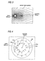
- Fig. 3 is a diagram showing an example of the fundus image model data stored in the memory 34.
- the fundus image model data is a schematic diagram data showing the running state of the nerve fiber bundle around the optic papilla and the central fovea (or the macula lutea) on the fundus of a typical and healthy eye, and is employed for dynamic perimetry, which will be described later.
- the fundus of the eye actually has a larger number of nerve fiber bundle, it is unnecessary for the fundus image model data to include all of the nerve fiber bundle. That is, it is sufficient for the fundus image model data to include an appropriate number of nerve fiber bundle, along which the examination target presented onto the eye E (fundus Ef) can be moved during perimetry that will be described later.
- An examiner or doctor turns on the light source 1 to illuminate the fundus Ef of the eye E with the infrared illumination light, and observes an image of the fundus Ef displayed on the monitor 31.
- the doctor moves the lens 11 in the optical axis direction so that the image of the fundus Ef is clearly displayed on the monitor 31.
- the control unit 30 moves the mirror 17 so that the mirror 17 is out of the optical axis L2 during the observation of the fundus Ef (with the exception of photographing the fundus Ef).
- the control unit30 displays an eye fixation target at a center of the LCD 20.
- the doctor depresses (manipulates) the switch 37a to obtain an image of the fundus Ef.
- the control unit 30 turns on the light source 18 to illuminate the fundus Ef with visible illumination light, and positions the mirror 17 on the light axis L2. Accordingly, an image of the fundus Ef is obtained by the camera 18.
- the control unit 30 switches, via the image switching unit 33, to switch a display on the monitor 31 from the observation image obtained by the camera 15 to the photographed image obtained by the camera 18.
- the image processing unit 32 performs appropriate image correction, such as tone correction, onto the image of the fundus Ef obtained by the camera 18 so that the processed color image of the fundus Ef is displayed on the monitor 31.
- the doctor confirms the displayed image of the fundus Ef, and then depresses (manipulates) a print switch (not shown) of the operation unit 37.
- the image of the fundus Ef thus obtained (displayed) is printed by a printer (not shown) , and the fundus Ef is examined.
- the position of the eye fixation target displayed on the LCD 20 may be changeable, and the image pickup area for the fundus Ef may be variable.
- the doctor manipulates the switch 37b to change the fundus photographing mode to the perimetry mode, and performs a dynamic perimetry, while referring to the observation image of the fundus Ef on the monitor 31 and the outputted (printed) image of the fundus Ef.
- the control unit 30 removes the mirror 17 out of the light axis L2, and switches a display on the monitor 31 from the photographed image obtained by the camera 18 to the observation image obtained by the camera 15.
- Fig. 4 is a diagram showing an example of the observation image 110 of the fundus Ef during perimetry.
- the doctor manipulates the group of keys 37c to designate the dimension (shape) of the examination target and the luminance A thereof, and then operates the input device 36 to move a cursor 100 displayed on the observation image 110 of the fundus Ef, to thereby designate a start position at which the examination target is to be initially presented on the fundus Ef and from which the examination is to be moved.
- this start position i.e. the moving and presentation start position, is designated on the circumferential edge of the observation image 110 of the fundus Ef displayed on the monitor 31.
- the control unit 30 After the moving and presentation start position of the examination target is designated, the control unit 30 presents the examination target at such a predetermined position on the LCD 20 as to correspond to the designated moving and presentation start position. Further, the control unit 30 moves the examination target at a predetermined speed (for example, 5° per second) toward the center of the LCD 20. Accordingly, the examination target is presented and moved from the peripheral portion of the fundus Ef toward the central fovea (the macula lutea)
- the control unit 30 uses the image processing unit 32 to display (form) a target mark 101a at such a position on the observation image 110 of the fundus Ef as to correspond to the examination target presentation position (the visually recognized position) at the time when the button 35 is depressed. That is to say, the position of the target mark 101a corresponds to the visually recognized position designated by the depression of the button 35 in this embodiment.
- an arrow 102a indicating the direction in which the examination target has been moved is also formed (displayed) adjacent to the target mark 101a.
- an examination target having the same luminance A is presented and moved from each start position toward the central fovea in a respective direction so that the isopter for the luminance A (the contour line of sensitivity with respect to the luminance A) is obtained.
- response information received from the patient is stored in the memory 34 one by one.
- an examination target having luminance B which is lower than the luminance A, is presented and moved toward the central fovea from the inside of the isopter for the luminance A so that an isopter for the luminance B is obtained in the similar manner as mentioned above.
- a target mark 101b is displayed (formed) at such a position on the observation image 110 of the fundus Ef that corresponds to the examination target presentation position (the visually recognized position) of the luminance B.
- an arrow 102b indicating the direction in which the examination target having the luminance B has been moved is also displayed (formed)
- the visual field sensitivity at each position on the fundus Ef is further examined dynamically.
- the isopters are substantially concentrically formed about the central fovea; however, in case the visual field has been altered by glaucoma, for example, the isopters are not concentrically formed. Since the visual field impairment produced by glaucoma, such as isolated scotoma, bow-shaped scotoma or a nose-oriented stairway effect, is considered to be the result of anerve fiber bundle disorder, and the progression of this impairment is developed along the line of the nerve fiberbundle.
- the doctor depresses (manipulates) the switch 37d, and thereafter moves the cursor 100 to designate positions of the optic papilla and the central fovea (or the macula lutea) on the observation image 110 of the fundus Ef displayed on the monitor 31.
- the control unit 30 retrieves the fundus image model data (see Fig. 3) from the memory 34. Thereafter, based on positioning information for the two positions designated by the cursor 100, the control unit 30 measures the distance between the two positions, and enlarges or reduces the schematic diagram produced using the fundus image model data, so that the distance between the optic papilla and the central fovea of the fundus image model data matches the distance between the two positions .
- control unit 30 displays the enlarged or reduced schematic diagram of the fundus image model data to be superimposed on the observation image 110 of the fundus Ef so that the optic papilla and the central fovea in the image of the fundus image model data are respectively aligned with the optic papilla and the central fovea in the observation image 110 of the fundus Ef.
- Fig. 5 is a diagram showing an example of the superimposed display in which the schematic diagram produced using the fundus image model data is superimposed on the observation image 110 of the fundus Ef on the monitor 31. With this display, the doctor need only view the monitor 31 to easily confirm the running state of the nerve fiber bundle on the fundus.
- the isopters formed in this embodiment have a deformed portion, i.e. the lower right portion in the paper plane, in which the isopter formed by the target marks 101b (the isopter of the luminance B) is deformed.
- Fig. 6 is a partially enlarged diagram showing the deformed portion of the isopter in Fig. 5.
- the doctor employs the cursor 100 to designate a moving and presentation start position P of an examination target again.
- the examination target having luminance A is used, because the examination target having the luminance A is currently regarded as having been visually recognized by the patient in a region outside the isopter formed by the target marks 101b.
- the doctor designates, as the moving and presentation start position P, a position slightly outside a specific position (for example, an target mark 101b1) of the deformed portion of the isopter formed by the target marks 101b.
- the control unit 30 When the position P has been designated, the control unit 30 presents the examination target at the position P and moves the presented examination target therefrom at a predetermined speed along a line of a nerve fiber bundle G that runs through the position P in a direction toward the isopter formed by the target marks 101a (in the direction indicated by an arrow Y1 in Fig. 6).
- the patient depresses the button 35 to transmit a response when the patient can visually recognize the presented examination target moved along the line of the nerve fiber bundle G.
- the control unit 30 displays a target mark 101a at such a position on the observation image 110 of the fundus Ef that corresponds to the examination target presentation position (the visually recognized position) designated by depressing the button 35.
- the doctor moves the cursor 100 to designate an arbitrary position on the nerve fiber bundle G along which the presented examination target has been moved.
- the control unit 30 presents an examination target at the designated arbitrary position on the nerve fiber bundle G, and moves the presented examination target from the designated arbitrary position in a direction perpendicular to the nerve fiber bundle G (in the direction indicated by an arrow Y2 in Fig. 6).
- the patient employs the button 35 to transmit a response of the visual recognition in the same manner as mentioned above, and the control unit 30 displays a target mark 101a based on this response.
- the doctor depresses (manipulates) an end switch (not shown) of the operation unit 37.
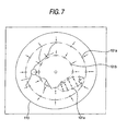
- the control unit 30 erases the fundus image model data from the monitor 31, and displays the isopters that provide a more detailed representation of the visual field sensitivity as shown in Fig. 7.
- the present invention is not limited thereby, and can be applied to a case in which the examination is performed after the static perimetry is performed. Further, in designating the moving direction of the examination target, two positions may be entered as desired by using the input device 36 to designate the start position and the direction of movement.
- the distance between the optic papilla and the central fovea (or the macula lutea) of the fundus observation image is employed to superimpose, on the display, the fundus observation image and the schematic diagram showing the running state of the nerve fiber bundle of the fundus image model data.
- positioning data for the optic papilla and the central fovea (themacula lutea) of the fundus observation image maybe employed to analyze the correlation between the fundus observation image and the fundus image model data, and to match the fundus observation image and the fundus image model data.
- the coordinates of the optic papilla and the central fovea (the macula lutea) of the fundus observation image displayed on the monitor may be obtained, and the schematic diagram showing the running state of the nerve fiber bundle may be superimposed on the fundus observation image so that the optic papilla and the central fovea 'or the macula lutea) of the fundus image model data are positioned at the obtained coordinates.
Landscapes
- Life Sciences & Earth Sciences (AREA)
- Health & Medical Sciences (AREA)
- Medical Informatics (AREA)
- Biophysics (AREA)
- Ophthalmology & Optometry (AREA)
- Engineering & Computer Science (AREA)
- Biomedical Technology (AREA)
- Heart & Thoracic Surgery (AREA)
- Physics & Mathematics (AREA)
- Molecular Biology (AREA)
- Surgery (AREA)
- Animal Behavior & Ethology (AREA)
- General Health & Medical Sciences (AREA)
- Public Health (AREA)
- Veterinary Medicine (AREA)
- Eye Examination Apparatus (AREA)
Applications Claiming Priority (2)
| Application Number | Priority Date | Filing Date | Title |
|---|---|---|---|
| JP2003340141A JP4250048B2 (ja) | 2003-09-30 | 2003-09-30 | 視野計 |
| JP2003340141 | 2003-09-30 |
Publications (2)
| Publication Number | Publication Date |
|---|---|
| EP1520511A1 true EP1520511A1 (de) | 2005-04-06 |
| EP1520511B1 EP1520511B1 (de) | 2013-07-17 |
Family
ID=34309036
Family Applications (1)
| Application Number | Title | Priority Date | Filing Date |
|---|---|---|---|
| EP04023354.6A Expired - Lifetime EP1520511B1 (de) | 2003-09-30 | 2004-09-30 | Perimeter |
Country Status (3)
| Country | Link |
|---|---|
| US (1) | US7309129B2 (de) |
| EP (1) | EP1520511B1 (de) |
| JP (1) | JP4250048B2 (de) |
Families Citing this family (14)
| Publication number | Priority date | Publication date | Assignee | Title |
|---|---|---|---|---|
| WO2006030658A1 (ja) * | 2004-09-15 | 2006-03-23 | Matsushita Electric Works, Ltd. | 視野計 |
| JP4757030B2 (ja) * | 2006-01-05 | 2011-08-24 | 株式会社ニデック | 視野計 |
| JP5011495B2 (ja) * | 2006-05-31 | 2012-08-29 | 株式会社ニデック | 眼科装置 |
| JP5048284B2 (ja) * | 2006-07-31 | 2012-10-17 | 株式会社ニデック | 眼科装置 |
| JP4806602B2 (ja) * | 2006-08-09 | 2011-11-02 | 興和株式会社 | 視野計 |
| JP4896621B2 (ja) * | 2006-08-09 | 2012-03-14 | 興和株式会社 | 視野計 |
| ES2632724T3 (es) * | 2010-02-25 | 2017-09-15 | Oculus Optikgeräte GmbH | Procedimiento perimétrico |
| JP5451484B2 (ja) * | 2010-03-29 | 2014-03-26 | 興和株式会社 | 視野計、及び視野計の制御方法 |
| GB201007697D0 (en) * | 2010-05-06 | 2010-06-23 | Ucl Business Plc | A supra-threshold test for use in detecting sensitivity loss across the field of vision |
| USD734471S1 (en) * | 2013-09-02 | 2015-07-14 | Ocuspecto Oy | Eye testing apparatus |
| US10736502B2 (en) | 2013-09-02 | 2020-08-11 | Ocuspecto Oy | Testing and determining a threshold value |
| USD738510S1 (en) * | 2014-10-02 | 2015-09-08 | Carl Zeiss Meditec, Inc. | Ophthalmic device |
| WO2019021986A1 (ja) * | 2017-07-24 | 2019-01-31 | 国立大学法人東北大学 | 視野計 |
| CN112022083B (zh) * | 2020-07-31 | 2023-02-10 | 上海理工大学 | 一种基于双向扫描的中央凹定位方法及系统 |
Citations (5)
| Publication number | Priority date | Publication date | Assignee | Title |
|---|---|---|---|---|
| US4279478A (en) * | 1977-10-05 | 1981-07-21 | Canon Kabushiki Kaisha | Eye examining instrument |
| US5037194A (en) * | 1988-05-31 | 1991-08-06 | Canon Kabushiki Kaisha | Ophthalmologic apparatus and method of compounding the image of an eye to be examined |
| US5463431A (en) * | 1993-09-16 | 1995-10-31 | Kabushiki Kaisha Topcon | Perimeter |
| US6053865A (en) | 1993-09-21 | 2000-04-25 | Kabushiki Kaisha Topcon | Retinal disease analyzer |
| US20030157464A1 (en) | 2002-02-20 | 2003-08-21 | Cesare Tanassi | Instrument for eye examination and method |
Family Cites Families (4)
| Publication number | Priority date | Publication date | Assignee | Title |
|---|---|---|---|---|
| US157464A (en) * | 1874-12-08 | Improvement in plows | ||
| US5323194A (en) | 1992-03-20 | 1994-06-21 | Humphrey Instruments Incorporated | Perimeter with non spherical bowl |
| JPH0654804A (ja) | 1992-08-05 | 1994-03-01 | Canon Inc | 視野計 |
| US6705726B2 (en) | 2002-02-20 | 2004-03-16 | Nidek Co., Ltd. | Instrument for eye examination and method |
-
2003
- 2003-09-30 JP JP2003340141A patent/JP4250048B2/ja not_active Expired - Fee Related
-
2004
- 2004-09-30 US US10/953,419 patent/US7309129B2/en not_active Expired - Fee Related
- 2004-09-30 EP EP04023354.6A patent/EP1520511B1/de not_active Expired - Lifetime
Patent Citations (5)
| Publication number | Priority date | Publication date | Assignee | Title |
|---|---|---|---|---|
| US4279478A (en) * | 1977-10-05 | 1981-07-21 | Canon Kabushiki Kaisha | Eye examining instrument |
| US5037194A (en) * | 1988-05-31 | 1991-08-06 | Canon Kabushiki Kaisha | Ophthalmologic apparatus and method of compounding the image of an eye to be examined |
| US5463431A (en) * | 1993-09-16 | 1995-10-31 | Kabushiki Kaisha Topcon | Perimeter |
| US6053865A (en) | 1993-09-21 | 2000-04-25 | Kabushiki Kaisha Topcon | Retinal disease analyzer |
| US20030157464A1 (en) | 2002-02-20 | 2003-08-21 | Cesare Tanassi | Instrument for eye examination and method |
Also Published As
| Publication number | Publication date |
|---|---|
| JP2005102948A (ja) | 2005-04-21 |
| US20050068498A1 (en) | 2005-03-31 |
| EP1520511B1 (de) | 2013-07-17 |
| US7309129B2 (en) | 2007-12-18 |
| JP4250048B2 (ja) | 2009-04-08 |
Similar Documents
| Publication | Publication Date | Title |
|---|---|---|
| EP1183992B1 (de) | Funduskamera | |
| US7506982B2 (en) | Ophthalmologic photographing apparatus | |
| US7959288B2 (en) | Ophthalmologic imager | |
| CN1951314A (zh) | 眼底相机 | |
| JP3592050B2 (ja) | 眼科装置 | |
| US7309129B2 (en) | Perimeter | |
| JP3888771B2 (ja) | 眼底カメラ | |
| JP3995806B2 (ja) | 眼科撮影装置 | |
| JP6003234B2 (ja) | 眼底撮影装置 | |
| JP4850561B2 (ja) | 眼科装置 | |
| JP3576671B2 (ja) | 眼科撮影装置 | |
| JP4011731B2 (ja) | 眼科装置 | |
| JP2005102946A (ja) | 視野計 | |
| JPH10118030A (ja) | 眼底撮影装置 | |
| JP3332489B2 (ja) | 検眼装置 | |
| JP3359117B2 (ja) | 眼屈折計 | |
| JPH0810221A (ja) | 眼底視野計 | |
| JPH10113336A (ja) | 眼科撮影装置 | |
| JP2002209855A (ja) | 眼底カメラ | |
| JP2005087301A (ja) | 眼科撮影装置 | |
| JPH0994223A (ja) | 眼科装置 | |
| JPH05168597A (ja) | 眼底カメラ | |
| JPH09271464A (ja) | 眼科装置 | |
| JPS6159134B2 (de) | ||
| JPH11169350A (ja) | 眼底撮影装置 |
Legal Events
| Date | Code | Title | Description |
|---|---|---|---|
| PUAI | Public reference made under article 153(3) epc to a published international application that has entered the european phase |
Free format text: ORIGINAL CODE: 0009012 |
|
| AK | Designated contracting states |
Kind code of ref document: A1 Designated state(s): AT BE BG CH CY CZ DE DK EE ES FI FR GB GR HU IE IT LI LU MC NL PL PT RO SE SI SK TR |
|
| AX | Request for extension of the european patent |
Extension state: AL HR LT LV MK |
|
| 17P | Request for examination filed |
Effective date: 20050810 |
|
| AKX | Designation fees paid |
Designated state(s): DE FR GB |
|
| 17Q | First examination report despatched |
Effective date: 20110706 |
|
| GRAP | Despatch of communication of intention to grant a patent |
Free format text: ORIGINAL CODE: EPIDOSNIGR1 |
|
| GRAS | Grant fee paid |
Free format text: ORIGINAL CODE: EPIDOSNIGR3 |
|
| GRAA | (expected) grant |
Free format text: ORIGINAL CODE: 0009210 |
|
| AK | Designated contracting states |
Kind code of ref document: B1 Designated state(s): DE FR GB |
|
| REG | Reference to a national code |
Ref country code: GB Ref legal event code: FG4D |
|
| REG | Reference to a national code |
Ref country code: DE Ref legal event code: R096 Ref document number: 602004042726 Country of ref document: DE Effective date: 20130912 |
|
| PLBE | No opposition filed within time limit |
Free format text: ORIGINAL CODE: 0009261 |
|
| STAA | Information on the status of an ep patent application or granted ep patent |
Free format text: STATUS: NO OPPOSITION FILED WITHIN TIME LIMIT |
|
| 26N | No opposition filed |
Effective date: 20140422 |
|
| GBPC | Gb: european patent ceased through non-payment of renewal fee |
Effective date: 20131017 |
|
| PG25 | Lapsed in a contracting state [announced via postgrant information from national office to epo] |
Ref country code: GB Free format text: LAPSE BECAUSE OF NON-PAYMENT OF DUE FEES Effective date: 20131017 |
|
| REG | Reference to a national code |
Ref country code: DE Ref legal event code: R097 Ref document number: 602004042726 Country of ref document: DE Effective date: 20140422 |
|
| REG | Reference to a national code |
Ref country code: FR Ref legal event code: PLFP Year of fee payment: 12 |
|
| PGFP | Annual fee paid to national office [announced via postgrant information from national office to epo] |
Ref country code: DE Payment date: 20150922 Year of fee payment: 12 |
|
| PGFP | Annual fee paid to national office [announced via postgrant information from national office to epo] |
Ref country code: FR Payment date: 20150811 Year of fee payment: 12 |
|
| REG | Reference to a national code |
Ref country code: DE Ref legal event code: R119 Ref document number: 602004042726 Country of ref document: DE |
|
| REG | Reference to a national code |
Ref country code: FR Ref legal event code: ST Effective date: 20170531 |
|
| PG25 | Lapsed in a contracting state [announced via postgrant information from national office to epo] |
Ref country code: DE Free format text: LAPSE BECAUSE OF NON-PAYMENT OF DUE FEES Effective date: 20170401 Ref country code: FR Free format text: LAPSE BECAUSE OF NON-PAYMENT OF DUE FEES Effective date: 20160930 |