EP1519247A1 - Reinigungsbürste zum Reinigen der Rückseite eines Bands - Google Patents
Reinigungsbürste zum Reinigen der Rückseite eines Bands Download PDFInfo
- Publication number
- EP1519247A1 EP1519247A1 EP04022836A EP04022836A EP1519247A1 EP 1519247 A1 EP1519247 A1 EP 1519247A1 EP 04022836 A EP04022836 A EP 04022836A EP 04022836 A EP04022836 A EP 04022836A EP 1519247 A1 EP1519247 A1 EP 1519247A1
- Authority
- EP
- European Patent Office
- Prior art keywords
- brush
- web
- back side
- imaging
- belt
- Prior art date
- Legal status (The legal status is an assumption and is not a legal conclusion. Google has not performed a legal analysis and makes no representation as to the accuracy of the status listed.)
- Withdrawn
Links
Images

Classifications
-
- G—PHYSICS
- G03—PHOTOGRAPHY; CINEMATOGRAPHY; ANALOGOUS TECHNIQUES USING WAVES OTHER THAN OPTICAL WAVES; ELECTROGRAPHY; HOLOGRAPHY
- G03G—ELECTROGRAPHY; ELECTROPHOTOGRAPHY; MAGNETOGRAPHY
- G03G21/00—Arrangements not provided for by groups G03G13/00 - G03G19/00, e.g. cleaning, elimination of residual charge
- G03G21/0005—Arrangements not provided for by groups G03G13/00 - G03G19/00, e.g. cleaning, elimination of residual charge for removing solid developer or debris from the electrographic recording medium
- G03G21/0035—Arrangements not provided for by groups G03G13/00 - G03G19/00, e.g. cleaning, elimination of residual charge for removing solid developer or debris from the electrographic recording medium using a brush; Details of cleaning brushes, e.g. fibre density
-
- G—PHYSICS
- G03—PHOTOGRAPHY; CINEMATOGRAPHY; ANALOGOUS TECHNIQUES USING WAVES OTHER THAN OPTICAL WAVES; ELECTROGRAPHY; HOLOGRAPHY
- G03G—ELECTROGRAPHY; ELECTROPHOTOGRAPHY; MAGNETOGRAPHY
- G03G21/00—Arrangements not provided for by groups G03G13/00 - G03G19/00, e.g. cleaning, elimination of residual charge
- G03G21/0005—Arrangements not provided for by groups G03G13/00 - G03G19/00, e.g. cleaning, elimination of residual charge for removing solid developer or debris from the electrographic recording medium
- G03G21/007—Arrangement or disposition of parts of the cleaning unit
- G03G21/0076—Plural or sequential cleaning devices
-
- G—PHYSICS
- G03—PHOTOGRAPHY; CINEMATOGRAPHY; ANALOGOUS TECHNIQUES USING WAVES OTHER THAN OPTICAL WAVES; ELECTROGRAPHY; HOLOGRAPHY
- G03G—ELECTROGRAPHY; ELECTROPHOTOGRAPHY; MAGNETOGRAPHY
- G03G2221/00—Processes not provided for by group G03G2215/00, e.g. cleaning or residual charge elimination
-
- G—PHYSICS
- G03—PHOTOGRAPHY; CINEMATOGRAPHY; ANALOGOUS TECHNIQUES USING WAVES OTHER THAN OPTICAL WAVES; ELECTROGRAPHY; HOLOGRAPHY
- G03G—ELECTROGRAPHY; ELECTROPHOTOGRAPHY; MAGNETOGRAPHY
- G03G2221/00—Processes not provided for by group G03G2215/00, e.g. cleaning or residual charge elimination
- G03G2221/0005—Cleaning of residual toner
- G03G2221/001—Plural sequential cleaning devices
-
- G—PHYSICS
- G03—PHOTOGRAPHY; CINEMATOGRAPHY; ANALOGOUS TECHNIQUES USING WAVES OTHER THAN OPTICAL WAVES; ELECTROGRAPHY; HOLOGRAPHY
- G03G—ELECTROGRAPHY; ELECTROPHOTOGRAPHY; MAGNETOGRAPHY
- G03G2221/00—Processes not provided for by group G03G2215/00, e.g. cleaning or residual charge elimination
- G03G2221/0026—Cleaning of foreign matter, e.g. paper powder, from imaging member
- G03G2221/0031—Type of foreign matter
- G03G2221/0042—Paper powder and other dry foreign matter
Definitions
- the present invention relates to the technology for removing residual ink and debris from the imaging surface of a printing system and more particularly to the cleaning of such residual ink and debris from the back of an imaging belt.
- Modern high speed and high quality printers require great precision in spacing tolerances and alignment within key imaging subsystems. Such precision is particularly important within the image development subsystem of electrostatographic imaging systems where toner ink is transferred from a donor element to a latent image characterized by differential charges on an imaging surface. Any significant variation across the imaging width in the gap between the donor element and the imaging surface results in irregular image density and in other imaging defects. Where the imaging surface comprises a flexible endless belt moving in relation to the donor element, maintaining precise tolerances is particularly difficult. In response, backer bars or other web guide members are commonly used to provide, support, tension, and precise alignment and tolerances of the belt as it moves through key imaging subsystems, including the development subsystem.
- residual toner and debris that collects on the back of a moving photoreceptor or other imaging surface can sufficiently distort tolerances to introduce imaging anomalies.
- Such residual toner and debris results from toner that escapes from the development subsystem or from a primary or secondary cleaning system, from toner shaken off the image surface or copy substrates, or from paper fibers and other debris that enters the system with copy substrates.
- some toner and debris escapes and is attracted to the back of the imaging belt, particularly when the back of the belt carries an electrical charge.
- the total amount of toner and debris is small, it can eventually accumulate on surfaces contacted by the back of the belt.
- Such surfaces include, without limitation, backer bars and other web guide members.
- toner is made to form a cloud of charged toner particles within the development gap. Toner particles are attracted out of such cloud toward the image areas on the imaging surface, which are oppositely charged. Toned images are thereby formed on the image surface. If the backer bars, which set the development gap between the photoreceptor and the donor elements, accumulate any significant amount of toner or debris, then the precise tolerances required across the entire image width of the gap are lost, and imaging defects result.
- HSD hybrid scavengeless development
- HJD hybrid jumping development
- Another consideration when designing a back of the belt cleaning is control of static charge build-up on the back of the web. Since the photoreceptor contains at least one insulating layer, charges can build on the back of the belt without being removed by the charging and discharging that occurs during the imaging cycle on the imaging side of the belt. Accordingly, it is common to utilize a static electricity removal device such as a grounded conductive brush. Such static removal device typically does not cover the entire width of the belt but instead covers only a sufficient width to remove enough charge to prevent harmful static charge build-up.
- One embodiment of the invention is a brush cleaner assembly for cleaning the back side of an imaging web having a width, comprising: a support structure located proximate to the back side of the web; a brush rotatably mounted on the support structure in an interfering relationship with the back side of the web such that a substantial portion of the width of the back side of the web is swept upon rotation of the brush; and a drive device, coupled to the rotatable brush, for imparting rotational force to the rotatable brush.
- the rotatable brush comprises a plurality of brushes.
- the brush cleaner assembly further comprises a power source electrically connected to the plurality of brushes wherein a first brush is charged to a certain electrical potential with one polarity and a second brush is charged to about the same electrical potential with the opposite polarity.
- the power source emits an AC signal wherein such signal is split to send signals of opposing polarity to the first and to the second brush.
- the power source comprises a bipolar power source with one polarity signal routed to the first brush and the other polarity routed to the second brush.
- the first brush is charged to a negative polarity.
- the current is bifurcated prior to conversion into alternating polarity current.
- the brush cleaner assembly further comprises at least one rectifying device electrically connected to the first brush for rectifying current routed to the first brush.
- the brush cleaner assembly further comprises a signal measurement and correction circuit electrically connected to both brushes for measuring electrical charges delivered to each brush and for sending corrective signals based upon such measurements.
- Another embodiment of the invention is a method for cleaning the back side of an imaging web having a width, comprising: locating a support structure proximate to the back side of the web rotatably mounting a brush on the support structure in an interfering relationship with the back side of the web such that a substantial portion of the width of the back side of the web is swept upon rotation of the brush; and imparting rotational force to the rotatable brush.
- the brush fibers interfere with the back side of the web about 2.16 millimeters.
- the brush is electrically charged between about 200 to about 500 volts.
- the brush is electrically charged to about 300 volts.
- the brush is rotated from between about 10 to about 100 revolutions per minute.
- the brush is rotated about 15 revolutions per minute.
- the rotatable brush comprises a plurality of brushes.
- the method further comprises connecting the plurality of brushes to at least one electrical power source wherein a first brush is charged to a certain electrical potential of one polarity and a second brush is charged to about the same electrical potential with the opposite polarity.
- the power source emits an AC signal wherein such signal is split to send signals of opposing polarity to the first and to the second brush.
- the power source comprises a bipolar power source with one polarity signal routed to the first brush and the other polarity routed to the second brush.
- the first brush is charged to a negative polarity.
- the current is bifurcated prior to conversion into alternating polarity current.
- the method further comprises at least one rectifying device electrically connected to the first brush for rectifying current routed to the first brush.
- the method further comprises a signal measurement and correction circuit electrically connected to both brushes for measuring electrical charges delivered to each brush and for sending corrective signals based upon such measurements.
- Yet another embodiment of the invention is an electrophotographic printer comprising: a brush cleaner assembly for cleaning the back side of an imaging web having a width, said cleaner assembly comprising a support structure located proximate to the back side of the web; a support structure located proximate to the back side of the web; a brush rotatably mounted on the support structure in an interfering relationship with the back side of the web such that a substantial portion of the width of the back side of the web is swept upon rotation of the brush; and a drive device, coupled to the rotatable brush, for imparting rotational force to the rotatable brush.
- An exemplary electronic system comprising one embodiment of the present invention is a multifunctional printer with print, copy, scan, and fax services.
- Such multifunctional printers are well known in the art and may comprise print engines based upon ink jet, electrophotography, and other imaging devices.
- the general principles of electrophotographic imaging are well known to many skilled in the art. Generally, the process of electrophotographic reproduction is initiated by substantially uniformly charging a photoreceptive member, followed by exposing a light image of an original document thereon. Exposing the charged photoreceptive member to a light image discharges a photoconductive surface layer in areas corresponding to non-image areas in the original document, while maintaining the charge on image areas for creating an electrostatic latent image of the original document on the photoreceptive member.
- This latent image is subsequently developed into a visible image by a process in which a charged developing material is deposited onto the photoconductive surface layer, such that the developing material is attracted to the charged image areas on the photoreceptive member. Thereafter, the developing material is transferred from the photoreceptive member to a copy sheet or some other image support substrate to which the image may be permanently affixed for producing a reproduction of the original document.
- the photoconductive surface layer of the photoreceptive member is cleaned to remove any residual developing material therefrom, in preparation for successive imaging cycles.
- the above described electrophotographic reproduction process is well known and is useful for both digital copying and printing as well as for light lens copying from an original.
- the process described above operates to form a latent image on an imaging member by discharge of the charge in locations in which photons from a lens, laser, or LED strike the photoreceptor.
- Such printing processes typically develop toner on the discharged area, known as DAD, or "write black” systems.
- Light lens generated image systems typically develop toner on the charged areas, known as CAD, or "write white” systems.
- Embodiments of the present invention apply to both DAD and CAD systems. Since electrophotographic imaging technology is so well known, further description is not necessary.
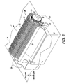
- cleaning system 20 one exemplary embodiment of a back of the belt cleaning system is shown as cleaning system 20.
- the primary component of cleaning system 20 is rotating electrostatically charged brush 21, which is mounted in housing 22.
- Brush 21 is rotated in a direction opposite to that of the inside of the photoreceptor belt, as indicated by arrows 11 and 12.
- Rotational speed of the brush is between about 10 and about 100 RPM and preferably about 15 RPM, which is considerably less than the typical 200-300 RPM of a primary brush cleaner for removing toner and debris from the imaging surface.
- the brush has an overall diameter of about 40 mm with fibers 23 extending radially from a conductive sleeve 24 for a distance of from about 10 to about 17 mm and preferably about 12.5 mm.
- the brush has an electrical bias of between about 150 to about 600 Volts and preferably about 215 Volts.
- the polarity of the electrical bias is opposite to that of the charged toner during image development.
- the brush fibers have a diameter of 10 denier or about 35 ⁇ m and contacts the back of the belt with an interference of between about 1.5 and about 3.0 mm, preferably about 2.16 mm. The combination of the electrical bias of the brush and the sweep of the bush fibers against the back of the photoreceptor surface effectively cleans and removes the residual toner and debris therefrom.
- cleaning system 20 In contrast to primary cleaning systems for cleaning residual toner and debris from the imaging surface, positioning of cleaning system 20 around the inside of belt 10 is not particularly important. This is because the rate of build-up of residual toner and debris is not sufficiently great to require cleaning before a particular imaging operation. Preferably, however, inside the belt cleaning system 20 is placed prior to the development subsystem. Wherever placed, continual operation of cleaning system 20 ensures cleaning of the inside of belt 10 at least once each revolution.
- Flicker bar 25 is made of any suitable material having low friction, non-wearing properties with respect to the material of the brush fibers, and non-sticking with respect to toner particles.
- High-density polyethylene has been found to be a suitable material for flicker bars.
- Nylon and acrylic fibers are also usually suitable.
- the material used is SA-7® from the Toray Company.
- Flicker bar is mounted in housing 22 in interfering contact with rotating brush 21.
- the amount of interference between flicker bar 25 and brush fibers 23 is between about 1.5 mm and about 4 mm, preferably about 2.5 mm.
- bar 25 is rotationally mounted to housing 22 and rotationally driven by motor 26.
- the rotational speed of brush 21 in this embodiment is approximately an order of magnitude less than the rotational speed of conventional brushes used to clean imaging surfaces.
- the amount of centrifugal force at the tips of each brush fiber are considerably less than the forces in conventional brush systems. More toner and debris is accordingly expected to stick to the flicker bar itself rather than to be flung away.
- Rotation of flicker bar 25 alleviates this problem since the arc segment of the bar that interferes with brush fibers 23 continually changes and itself becomes cleaned by the brush fibers as flicker bar 25 rotates.
- flicker bar 25 and brush fibers 23 are used for such interference so that the density of any particles that stick to flicker bar 25 is accordingly less. Without rotation, it is possible for flicker bar 25 and brush fibers 23 to trade toner and debris between themselves without sufficiently removing the toner and debris from the back of the belt.
- flicker bar 25 results from using the rotation of flicker bar 25 to drive rotation of brush 21. Because brush 21 rotates between about 10 to about 100 RPM, and preferably about 15 RPM, reduction from the rotational speed of motor 26 is required. Space inside the confines of endless loop 10 is extremely tight for the reasons described above, and a motor and gear system to drive brush 21 separately from flicker bar 25 would add both expense and space. Accordingly, flicker bar 25 itself is used to convey rotational drive from motor 26 to brush 21. Gear reduction is accomplished by attaching a relatively small gear such as 20-tooth gear 27 to the end of flicker bar 25. Gear 27, in turn, engages large gear 28, which is mounted to the end of and drives brush 21.
- Gear 28 may have about 60 teeth in order to give a 3-1 gear reduction between flicker bar 25 and brush 21. Reductions from about 2-1 to about 5-1 are also reasonable. Yet another advantage of this arrangement is the ability to position some of the space consuming hardware on one side of cleaning system 20 and the remainder on the other side. If both the motor and all of the gears were placed on the same side, too much space on that side is likely to be consumed, thereby leading to the undesirable need to increase the size and cost of the entire system.
- gears 27 and 28 are shown directly coupled as is rotating brush 26 and rotating flicker bar 25.
- coupling may comprise any assortment of drive coupling mechanisms and may include intermediate gears or other coupling mechanisms.
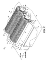
- FIG 2 a dual brush back of the belt cleaning system is shown.
- dual brushes and flicker bars each operate in the same manner as shown in Figure 1.
- One brush and flicker bar system is labeled identically as in Figure 1 while the second brush is labeled with corresponding numbers scaled a decade higher.
- One skilled in the art will readily understand that one motor could drive both systems with appropriate gearing or other coupling.
- brush 21 is negatively charged by connection to power source 51 whereas brush 31 is positively charged by connection with power source 52.
- Power sources 51 and 52 can be DC only power sources or may generate AC oscillating current with appropriate DC rectifiers. In one possible configuration, power source 51 and 52 are combined into one AC current source that is split with the positive polarity of its signal being directed to brush 31 and the negative polarity being directed to brush 21. Additionally, it is understood that the polarity of brushes 21 and 31 can be reversed.
- each brush has opposite polarity
- the first brush uniformly charges the entire width of belt 10 with a charge of a first polarity. Any pre-existing static on the belt is subsumed within the 200-500 Volt charge to create uniformity.
- the opposite and equal polarity of the next brush then erases or neutralizes the charge across the full width of the belt. The result is that this active charge removal system creates significantly more charge uniformity on the back of the belt than the conventional passive charge removal systems.
- DC power supply 53 provides DC current which is split, or bifurcated, into circuits directed to brush 21 and brush 31, respectively.
- a pulse wave modulator controlled converter, 54 and 55 respectively, converts the DC current into pulsed AC current (typically in a square wave signal).
- Current is carried from converters 54 and 55 through lines 56 and 57 to respective rectifying diodes 58 and 59.
- Diode 58 emits the negative portion of the pulsed signal, thereby charging brush 21 to a negative potential.
- Diode 59 emits the positive portion of the pulsed signal, thereby charging brush 31 to a negative potential.
- Figure 3 also shows a schematic for a signal measurement, correction and fault control device 60.
- This device operates by receiving signals form lines 56 and 57 through lines 66 and lines 65, respectively. These signals are measured and compared by device 60 to ensure that signals of equal voltage, amperage, and pulse shape are being sent to respective brushes 21 and 31. Any corrective signal is sent back to lines 56 or 64 through respective lines 61 and 64.
- signal measurement, correction, and fault control circuits and devices such as device 60 are well known in the art and may be accomplished by a wide variety of particular circuit elements. Use of such a measurement and correction device helps ensure that the charges on brushes 21 and 31 are equal but of opposite polarity in order to optimize static charge removal.
- embodiments of the back of the belt cleaning system of the present invention include a rotating flicker bar that enables more compact and inexpensive drive of a cleaning brush while also better removing residual toner and debris from the fibers of the brush. Additionally, dual cleaning brushes charged with opposite polarity provide superior means for uniformly discharging static charges from the back of an imaging belt.
Landscapes
- Physics & Mathematics (AREA)
- General Physics & Mathematics (AREA)
- Cleaning In Electrography (AREA)
- Accessory Devices And Overall Control Thereof (AREA)
- Paper Feeding For Electrophotography (AREA)
- Advancing Webs (AREA)
Applications Claiming Priority (4)
| Application Number | Priority Date | Filing Date | Title |
|---|---|---|---|
| US50654503P | 2003-09-26 | 2003-09-26 | |
| US506545P | 2003-09-26 | ||
| US10/876,708 US7162177B2 (en) | 2003-09-26 | 2004-06-25 | Back of the belt cleaner in an imaging system |
| US876708 | 2004-06-25 |
Publications (1)
| Publication Number | Publication Date |
|---|---|
| EP1519247A1 true EP1519247A1 (de) | 2005-03-30 |
Family
ID=34198325
Family Applications (1)
| Application Number | Title | Priority Date | Filing Date |
|---|---|---|---|
| EP04022836A Withdrawn EP1519247A1 (de) | 2003-09-26 | 2004-09-24 | Reinigungsbürste zum Reinigen der Rückseite eines Bands |
Country Status (3)
| Country | Link |
|---|---|
| US (1) | US7162177B2 (de) |
| EP (1) | EP1519247A1 (de) |
| JP (1) | JP2005104153A (de) |
Cited By (1)
| Publication number | Priority date | Publication date | Assignee | Title |
|---|---|---|---|---|
| CN108792735A (zh) * | 2018-07-09 | 2018-11-13 | 湖州鑫瑞辰纺织科技有限公司 | 一种具有清洁功能的纺织布料卷布机 |
Families Citing this family (2)
| Publication number | Priority date | Publication date | Assignee | Title |
|---|---|---|---|---|
| JP5037079B2 (ja) * | 2006-09-19 | 2012-09-26 | 株式会社リコー | クリーニング装置、プロセスカートリッジ及び画像形成装置 |
| JP6701808B2 (ja) | 2016-03-01 | 2020-05-27 | セイコーエプソン株式会社 | 印刷装置 |
Citations (4)
| Publication number | Priority date | Publication date | Assignee | Title |
|---|---|---|---|---|
| EP0472401A2 (de) | 1990-08-20 | 1992-02-26 | Xerox Corporation | Gerät zur Oberflächenreinigung für die elektrophotographische Bilderstellung |
| EP0747788A2 (de) * | 1995-06-07 | 1996-12-11 | Xerox Corporation | Reinigungsgerät und Verfahren zum Entfernen von Teilchen von einer Oberfläche |
| US5771424A (en) | 1993-10-22 | 1998-06-23 | Xerox Corporation | Preconditioning of photoreceptor and cleaner brush |
| US6418285B1 (en) | 2000-10-27 | 2002-07-09 | Xerox Corporation | BOB cleaners to control and maintain PR module motion quality latitude |
Family Cites Families (16)
| Publication number | Priority date | Publication date | Assignee | Title |
|---|---|---|---|---|
| US2832977A (en) | 1952-02-05 | 1958-05-06 | Haloid Co | Electrostatic cleaning device |
| US3722018A (en) | 1971-11-08 | 1973-03-27 | Xerox Corp | Cleaning apparatus |
| US4435073A (en) | 1982-08-16 | 1984-03-06 | Xerox Corporation | Toner removal apparatus |
| JPH0229222B2 (ja) * | 1984-10-31 | 1990-06-28 | Fuji Xerox Co Ltd | Seidenshikiburashikuriiningusochi |
| US4851880A (en) | 1988-06-24 | 1989-07-25 | Eastman Kodak Company | Cleaning apparatus having airfoils |
| JPH04335695A (ja) * | 1991-05-13 | 1992-11-24 | Mita Ind Co Ltd | クリーニング装置 |
| JPH06161335A (ja) * | 1992-07-03 | 1994-06-07 | Fuji Xerox Co Ltd | 電子写真複写機等の画像形成装置 |
| US5315358A (en) | 1993-04-19 | 1994-05-24 | Xerox Corporation | Flicker bar with an integral air channel |
| JPH0739736U (ja) * | 1993-12-30 | 1995-07-18 | 秀一 新山 | 網戸洗浄装置 |
| US5784674A (en) * | 1995-06-29 | 1998-07-21 | Fuji Xerox Co., Ltd. | Inner face cleaning member for an intermediate transfer device |
| US5600425A (en) * | 1995-12-18 | 1997-02-04 | Xerox Corporation | Cleaner system with central augering |
| JPH10198092A (ja) * | 1997-01-10 | 1998-07-31 | Hitachi Koki Co Ltd | 電子写真装置における給送ローラの清掃装置 |
| US6259882B1 (en) * | 1999-11-24 | 2001-07-10 | Xerox Corporation | Cleaning brush for non-imaging surfaces in an electrostatographic printer or copier |
| JP2001255749A (ja) * | 2000-03-13 | 2001-09-21 | Ricoh Co Ltd | 画像形成装置 |
| JP2002023254A (ja) * | 2000-07-06 | 2002-01-23 | Fuji Photo Film Co Ltd | インスタントフイルムユニット用現像液展開装置 |
| US6961534B2 (en) * | 2003-09-26 | 2005-11-01 | Xerox Corporation | Rotating flicker bar for cleaning a rotating cleaner roll and for transmitting power to the cleaner roll |
-
2004
- 2004-06-25 US US10/876,708 patent/US7162177B2/en not_active Expired - Fee Related
- 2004-09-21 JP JP2004272698A patent/JP2005104153A/ja active Pending
- 2004-09-24 EP EP04022836A patent/EP1519247A1/de not_active Withdrawn
Patent Citations (4)
| Publication number | Priority date | Publication date | Assignee | Title |
|---|---|---|---|---|
| EP0472401A2 (de) | 1990-08-20 | 1992-02-26 | Xerox Corporation | Gerät zur Oberflächenreinigung für die elektrophotographische Bilderstellung |
| US5771424A (en) | 1993-10-22 | 1998-06-23 | Xerox Corporation | Preconditioning of photoreceptor and cleaner brush |
| EP0747788A2 (de) * | 1995-06-07 | 1996-12-11 | Xerox Corporation | Reinigungsgerät und Verfahren zum Entfernen von Teilchen von einer Oberfläche |
| US6418285B1 (en) | 2000-10-27 | 2002-07-09 | Xerox Corporation | BOB cleaners to control and maintain PR module motion quality latitude |
Cited By (1)
| Publication number | Priority date | Publication date | Assignee | Title |
|---|---|---|---|---|
| CN108792735A (zh) * | 2018-07-09 | 2018-11-13 | 湖州鑫瑞辰纺织科技有限公司 | 一种具有清洁功能的纺织布料卷布机 |
Also Published As
| Publication number | Publication date |
|---|---|
| US7162177B2 (en) | 2007-01-09 |
| US20050069339A1 (en) | 2005-03-31 |
| JP2005104153A (ja) | 2005-04-21 |
Similar Documents
| Publication | Publication Date | Title |
|---|---|---|
| US6654574B2 (en) | Method and apparatus for image forming performing improved cleaning and discharging operations on image forming associated members | |
| US4870466A (en) | Cleaning device having fur brush, scavenger roller and scraper for electrostatic recorder | |
| JP5006493B2 (ja) | 画像形成装置 | |
| US5652951A (en) | Detoning cycle to increase brush life and reduce emissions by removing accumulated toner | |
| CN101145008A (zh) | 带电装置及图像形成装置 | |
| EP1519247A1 (de) | Reinigungsbürste zum Reinigen der Rückseite eines Bands | |
| US5678142A (en) | Image forming apparatus having simultaneous developing/cleaning and residual toner contact charging device | |
| US6961534B2 (en) | Rotating flicker bar for cleaning a rotating cleaner roll and for transmitting power to the cleaner roll | |
| US20100119253A1 (en) | Image forming apparatus and method for cleaning image carrier of the image forming apparatus | |
| US20060083538A1 (en) | Image forming apparatus | |
| JPH117229A (ja) | 表面から粒子を除去する装置 | |
| JPH0239186A (ja) | クリーナ | |
| JP3330478B2 (ja) | 画像形成装置 | |
| JP2767951B2 (ja) | 接触帯電部材 | |
| JP3434413B2 (ja) | 画像形成装置 | |
| JP2001265189A (ja) | 画像形成装置 | |
| JP4744240B2 (ja) | 画像形成装置のクリーニング装置 | |
| JP2009037053A (ja) | 画像形成装置 | |
| JP3303995B2 (ja) | クリーニング・現像剤供給装置 | |
| JPH08262943A (ja) | 電子写真式印刷装置 | |
| JP2000010450A (ja) | クリーニング装置 | |
| JPH1195549A (ja) | 画像形成装置 | |
| JPH0854814A (ja) | クリーニング装置 | |
| JPH01179974A (ja) | 感光体クリーニング装置 | |
| JPH0850437A (ja) | クリーニング装置 |
Legal Events
| Date | Code | Title | Description |
|---|---|---|---|
| PUAI | Public reference made under article 153(3) epc to a published international application that has entered the european phase |
Free format text: ORIGINAL CODE: 0009012 |
|
| AK | Designated contracting states |
Kind code of ref document: A1 Designated state(s): AT BE BG CH CY CZ DE DK EE ES FI FR GB GR HU IE IT LI LU MC NL PL PT RO SE SI SK TR |
|
| AX | Request for extension of the european patent |
Extension state: AL HR LT LV MK |
|
| 17P | Request for examination filed |
Effective date: 20050930 |
|
| AKX | Designation fees paid |
Designated state(s): DE FR GB |
|
| 17Q | First examination report despatched |
Effective date: 20091113 |
|
| GRAP | Despatch of communication of intention to grant a patent |
Free format text: ORIGINAL CODE: EPIDOSNIGR1 |
|
| STAA | Information on the status of an ep patent application or granted ep patent |
Free format text: STATUS: THE APPLICATION IS DEEMED TO BE WITHDRAWN |
|
| 18D | Application deemed to be withdrawn |
Effective date: 20121221 |