EP0747788A2 - Reinigungsgerät und Verfahren zum Entfernen von Teilchen von einer Oberfläche - Google Patents
Reinigungsgerät und Verfahren zum Entfernen von Teilchen von einer Oberfläche Download PDFInfo
- Publication number
- EP0747788A2 EP0747788A2 EP96304083A EP96304083A EP0747788A2 EP 0747788 A2 EP0747788 A2 EP 0747788A2 EP 96304083 A EP96304083 A EP 96304083A EP 96304083 A EP96304083 A EP 96304083A EP 0747788 A2 EP0747788 A2 EP 0747788A2
- Authority
- EP
- European Patent Office
- Prior art keywords
- brush
- deformable member
- cleaning
- photoreceptor
- contact
- Prior art date
- Legal status (The legal status is an assumption and is not a legal conclusion. Google has not performed a legal analysis and makes no representation as to the accuracy of the status listed.)
- Pending
Links
Images



Classifications
-
- G—PHYSICS
- G03—PHOTOGRAPHY; CINEMATOGRAPHY; ANALOGOUS TECHNIQUES USING WAVES OTHER THAN OPTICAL WAVES; ELECTROGRAPHY; HOLOGRAPHY
- G03G—ELECTROGRAPHY; ELECTROPHOTOGRAPHY; MAGNETOGRAPHY
- G03G21/00—Arrangements not provided for by groups G03G13/00 - G03G19/00, e.g. cleaning, elimination of residual charge
- G03G21/0005—Arrangements not provided for by groups G03G13/00 - G03G19/00, e.g. cleaning, elimination of residual charge for removing solid developer or debris from the electrographic recording medium
- G03G21/0035—Arrangements not provided for by groups G03G13/00 - G03G19/00, e.g. cleaning, elimination of residual charge for removing solid developer or debris from the electrographic recording medium using a brush; Details of cleaning brushes, e.g. fibre density
-
- G—PHYSICS
- G03—PHOTOGRAPHY; CINEMATOGRAPHY; ANALOGOUS TECHNIQUES USING WAVES OTHER THAN OPTICAL WAVES; ELECTROGRAPHY; HOLOGRAPHY
- G03G—ELECTROGRAPHY; ELECTROPHOTOGRAPHY; MAGNETOGRAPHY
- G03G21/00—Arrangements not provided for by groups G03G13/00 - G03G19/00, e.g. cleaning, elimination of residual charge
- G03G21/0005—Arrangements not provided for by groups G03G13/00 - G03G19/00, e.g. cleaning, elimination of residual charge for removing solid developer or debris from the electrographic recording medium
- G03G21/007—Arrangement or disposition of parts of the cleaning unit
- G03G21/0076—Plural or sequential cleaning devices
-
- G—PHYSICS
- G03—PHOTOGRAPHY; CINEMATOGRAPHY; ANALOGOUS TECHNIQUES USING WAVES OTHER THAN OPTICAL WAVES; ELECTROGRAPHY; HOLOGRAPHY
- G03G—ELECTROGRAPHY; ELECTROPHOTOGRAPHY; MAGNETOGRAPHY
- G03G2221/00—Processes not provided for by group G03G2215/00, e.g. cleaning or residual charge elimination
- G03G2221/0005—Cleaning of residual toner
- G03G2221/001—Plural sequential cleaning devices
Definitions
- This invention relates generally to a cleaning apparatus and method for removing particles from a surface and more particularly concerns a retracting cleaning brush.
- a charge retentive surface i.e., photoconductor, photoreceptor or imaging surface
- a charge retentive surface i.e., photoconductor, photoreceptor or imaging surface
- the resulting pattern of charged and discharged areas on that surface form an electrostatic charge pattern (an electrostatic latent image) conforming to the original image.
- the latent image is developed by contacting it with a finely divided electrostatically attractable powder referred to as "toner". Toner is held on the image areas by the electrostatic charge on the surface.
- Toner is held on the image areas by the electrostatic charge on the surface.
- the toner image may then be transferred to a substrate (e.g., paper), and the image affixed thereto to form a permanent record of the image to be reproduced. Subsequent to development, excess toner left on the charge retentive surface is cleaned from the surface.
- a substrate e.g., paper
- excess toner left on the charge retentive surface is cleaned from the surface.
- a commercially successful mode of cleaning employed on automatic xerographic devices utilizes a brush with soft electrically biased conductive fiber bristles or with insulative soft bristles which have suitable triboelectric characteristics.
- the brush fibers retain particles removed from the surface.
- a detoning roll is one common method of removing these particles from the cleaning brush fibers.
- US-A-5,260,754 discloses a cleaning device incorporated in an image forming apparatus for removing a toner remaining on a photoconductive drum by a fur brush and collecting the removed toner by a collecting roller.
- the cleaning device selectively moves the fur brush into and out of contact with both of the photoconductive drum and collecting roller.
- US-A-5,177,553 discloses a method of controlling rotation of a brush in a cleaning device of an image forming system.
- the brush is raced together with the photoreceptor which is in contact with the brush for a predetermined time in a warming-up period before the image forming operation starts, in an image-forming rest period, or when a new cartridge constituted by the photoreceptor and the cleaning device is set into the image forming system, so that the fibers of the brush which have been transformed during the rest of rotation are recovered into their original shapes.
- an apparatus having a cleaning subsystem for removing particles from a surface in a printing machine, having an operational mode and a non-operational mode, comprising: a deformable member for removing the particles from the surface; member in contact with the deformable member; and means for moving the deformable member into and out of contact with the member to prevent the formation of a planar region on the deformable member.
- a method for removing particles from a surface, with a rotatable deformable member, in an electrostatographic machine having a cleaning subsystem, in contact with a member comprising: stopping operation of the cleaning subsystem; stopping rotation of the deformable member; and retracting the rotatable deformable member about a pivot, out of contact with the member to prevent contact therebetween in a common area for a substantial period of time to prevent forming a planar region on the rotatable deformable member.
- Figure 1 shows a prior art elevational view of a cleaner brush 20 in contact with a detoning roll 50 which causes a flat spot 40 in the brush.
- the brush 20 rotates in the direction indicated by arrow 25, in the against-mode relative to the direction of movement of the photoreceptor 10.
- the detoning roll 50 rotates in a direction indicated by arrow 55.
- the detoning roll 50 is contacted by the brush fibers 30 in a flicking action to remove toner particles from the brush fibers 30.
- an electrostatic brush detoning roll cleaner is in the standby mode and the brush is stationary, the brush 20 after time will take a set in the nip region between the brush 20 and any contacting surface (e.g. photoreceptor 10, detoning roll 50).
- the brush fibers 30 will deform in such a way as to cause a flat spot 40 in the brush 20.
- This flat spot 40 impairs cleaning and impacts photoreceptor motion quality.
- the present invention retracts the brush 20 from the contact regions of the photoreceptor 10 and the detoning roll 50, when the cleaner is in the standby mode (see Figure 4).
- the lack of contact between the brush 20 and the contact regions, during standby prevents flat spots 40 from occurring in the brush 20. Also, this lack of contact allows any set of the fibers incurred during the cleaning operation to at least, partially recover during standby.
- Electrostatic brush detoning roll cleaners operate by removing the residual toner 80 from the photoreceptor 10 both with mechanical and electrostatic forces.
- the fibers 30 on the brush 20 touch the residual toner on the photoreceptor 10 in the photoreceptor/brush 15 nip region.
- the toner 80 is then transported by the brush to the detoning roll 50 and the brush 20 touches the detoning nip region.
- the brush fibers 30 will deform due to the contact areas around the brush 20.
- a flat spot 40 will occur if the brush is stationary for a long enough period of time. When the brush is rotated again, the flat spot will slowly disappear.
- both the cleaning function and the motion quality of the photoreceptor 10 can be damaged.
- the recovery time of deflected brush fibers to a straight condition is a function of temperature, relative humidity, fiber material and stress history. Therefore, depending on conditions, the fibers may fully recover or some permanent deflection may remain.
- FIG. 2 shows is a prior art elevational view of a flat spot created by the detoning roll rotating about the brush axis.
- Brush cleaning is dependent upon the number of brush fibers 30 touching the photoreceptor 10 during cleaning.
- the number of brush fibers 30 touching the photoreceptor 10 is reduced.
- the brush flat spot 40 region will not effectively clean toner from the photoreceptor 10 due to a decrease in brush fibers 30 contacting the photoreceptor 10.
- the flat spot 40 causes a drag transient on the photoreceptor 10 which adversely affects photoreceptor motion quality.
- the compression force from the brush 20 is also dependent on the number of brush fibers 30 touching the photoreceptor 10 and their interference to the photoreceptor 10.
- the number of brush fibers 30 touching the photoreceptor 10 is reduced and there is locally less interference between the brush fibers 30 and the photoreceptor 10.
- the brush flat spot 40 region will cause a decrease in the compression force on the photoreceptor 10 from the brush 20.
- a decrease in compression or normal force on the photoreceptor 10 will cause a decrease in drag on the photoreceptor 10. This decrease or change in the drag can cause motion quality errors depending on the magnitude of the drag change and how fast the drag changes which is dependent on brush speed.
- the brush 20 is removed from regions (e.g. photoreceptor, detoning roll) where the brush flat spot 40 will occur. (see Figure 4.) Without contact with the brush fibers 30, a brush flat spot will not occur. A flat spot can occur at the brush to photoreceptor contact region 15, the brush to detoning roll region, brush to flicker bar region, or possibly brush to housing region. Removing or retracting the brush from contact regions would be expensive for conventional brush cleaners, which have relatively few moving parts.
- the brush, auger, and detoning rolls each rotate but do not move relative to the contact regions where the brush flat spot can occur. Additional solenoids and motors would have to be added to move the brush from the contact regions.
- a multi-pass color cleaner has cleaner components that move relative to the contact regions.
- the cleaner In a multi-pass operation, the cleaner must be removed from the photoreceptor until after the image is transferred. If the cleaner is not removed, the cleaner will remove the untransferred toner image.
- the brush In this case of a brush cleaner, the brush is removed from the photoreceptor.
- the brush flat spot 40 can be removed very inexpensively. When the brush is in stand by or the machine is off, the brush should be off the photoreceptor 10.
- the brush rotates around a carefully chosen pivot point, the flat spots due to housings, flicker bars, and detoning rolls can be avoided (see Figure 8) by positioning the pivot so that there are no contact regions when the brush is retracted from the photoreceptor 10.
- the brush would rotate about the pivot point to move away from the photoreceptor and away from the detoning roll.
- the pivot point is chosen so that the variation in interference to the detoning roll is minimized for variations in the interference and location of the brush against the photoreceptor. This is accomplished by the brush coming into contact with the detoning roll on an arc tangent to the detoning roll surface.
- the present invention decreases the rate at which the brush takes a set.
- the brush fibers which take a set during normal use can recover from that set. Set recovery extends the useful life of the brush. This is especially important for short pile height, small diameter brushes.
- the shorter pile heights result in stiffer brush fibers which take a set sooner because of higher strains and give larger compression forces on the photoreceptor which yields higher drag forces.
- the fiber strikes of smaller brushes are also more effected by tolerances and the presence of flat spots. All these factors are reasons for the present invention to retract the brush from contact from surfaces.
- a single pass brush cleaner which normally would not have a retraction mechanism is also retracted, in the present invention, to avoid brush flat spots.
- Figure 3 shows an elevational view of a brush and housing mounted to a retraction pivot arm.
- the pivot arm 65 is capable of rotating about a retraction pivot 60 with the brush in contact with the photoreceptor and the detoning roll 50.
- the brush housing 100 surrounding the retractable cleaning brush maintains a close clearance to the brush to minimize toner emissions.
- the cleaner housing moves with the brush as it retracts. This is accomplished by mounting the cleaner housing to endplates which contain brush bearings 90. The endplates are then mounted to the pivot arms which rotate to retract the brush and housing.
- the pivot arm allows a simple drive to the brush 20 through a drive shaft located at the pivot 60.
- the brush diameter decreases due to set of the brush fibers caused by the interferences in the photoreceptor and detoning roll nips.
- This is a time and environment dependent phenomenon which is reversible over relaxation time periods of no fiber deflection for at least as long as the time duration during which the fiber was deflected. Since the relaxation time periods are not sufficient to offset the brush diameter reduction, in time the brush will have to be replaced because the number of fibers striking the photoreceptor is insufficient for good cleaning.
- the interferences to the photoreceptor and to the detoning roll can be increased as the brush diameter decreases.
- the interferences are to be increased such that the photoreceptor interference always remains less than the detoning roll interference. This is accomplished by proper positioning of the detoning roll and retraction pivot. Increasing the interference of the brush can be done at predetermined copy count intervals, by the tech rep as required for good cleaning, or through an automatic sensing system (e.g., brush size, brush compression force, brush electrical current, etc.).
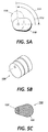
- Another method would use a multiple position cam 120 that creates different amounts of interference on different positions of the cam 120, as shown in Figure 5B as an isometric view.
- the position of the cam 120 to be used can be changed automatically or by a technical representative.
- Figure 5C shows a third method to change interference involving the use of a compressible material for the portion of the cam 130 controlling interference.
- the compressible material portion 131 of the cam is chosen to match the set properties of the brush fibers 30 such that as the brush fibers 30 take a set, the cam also takes a set and allows the brush interference to increase at the same rate as the brush diameter decreases.
- the compressible material portion 131 of the cam includes urethane, nylon or other plastics.
- the remaining portion of the cam material 132 includes metal or plastics such as delrin, polycarbonate, nylon, acetal or others. In all of these methods, the cleaner brush is not subjected to increasing interferences until the brush diameter has decreased.
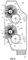
- the dual electrostatic brush cleaner comprises two brushes 20, 22 in a cleaner housing 150.
- Each brush 20, 22 rotates in a direction shown by arrows 25, 24, respectively, which in this case is against that of the direction of motion of the photoreceptor 10.
- the fibers 30, 32 of the brush remove toner 80 from the photoreceptor 10 as the brushes, 20, 22 rotate.
- the toner 80 is removed from the brush fibers by electrostatic attraction of the toner to the biased roll surface that occurs when the fibers 30, 32 contact the detoning rolls 50, 52.
- the detoning rolls 50, 52 rotate in the same direction, shown by arrows 55, 54, respectively, as the cleaning brushes 20, 22.
- Scraper blades 160, 162 remove the toner particles 80 adhering to the detoning rolls 55, 54.
- the cleaning apparatus When the cleaning apparatus is in a 3 o'clock or 9 o'clock position, the toner particles 80 gravitationally fall into a waste bottle container 190.
- Flexible seals 180, 182 prevent the toner particles from falling onto the photoreceptor surface.
- the retracted cleaning brushes 20, 22 of the present invention are held stationary, so as not to contaminate the photoreceptor 10 or machine with unwanted toner emissions caused by rotating retracted cleaning brushes.
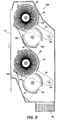
- the cleaning element In a multi-pass operation, the cleaning element must be retracted (not in contact with the photoreceptor 10) until after the image is transferred. If the cleaning element is not retracted, the cleaner will remove the untransferred toner layer. Upon retraction, if the cleaning brush is left rotating, the toner emissions caused by the spinning motion can collect on the photoreceptor 10, making for an unsatisfactory image (see Figure 7). By stopping the brush 20 from rotating (i.e. spinning) immediately after being retracted from the photoreceptor 10, little or no emissions will be sent from the brush 20 onto the photoreceptor 10 or into the machine (see Figure 8). When the cleaner is engaged (in contact with the photoreceptor 10), normal brush rotation should occur.
- the brush 20 and detoning roll 50 rotations are controlled by a clutch (not shown). Engaging the clutch connects the brush 20 and detoning roll 50 shafts to the rotating drive shaft. Disengaging the clutch removes the connection and allows the brush 20 and detoning roll 50 to freely spin. Friction in the system will stop the rotation. That friction is supplied by bearing friction, brush deflection in the cleaning and detoning nips (which decreases as the brush is retracted), seals rubbing on the ends of the brush and on the detoning roll and by the detoning blade 160 scraping on the detoning roll surface.
- the detoning blade 160 is the largest component of the frictional forces and acts as a brake.
- An embodiment of the present invention in a dual (or more) brush system governed by a clutch involves simultaneous control of the rotation of all of the brushes.
- the first brush 20 that engages the photoreceptor 10 surface begins to rotate.
- This first brush 20 determines when the second (i.e. remaining) brush 22 begins rotation.
- the last brush to retract from the photoreceptor 10 surface stops rotating.
- Figure 6 shows dual cleaning brushes 20, 22 engaged with the photoreceptor 10 during the cleaning operation.
- the cleaning brush is rotating in opposition to the photoreceptor.
- Figure 7 shows the cleaning brush retracted and shows the toner emissions when the cleaning brush is left rotating during the multi-pass color operation. Toner emissions from the cleaning brush are inevitable when the cleaning brush is kept rotating due to contact with adjacent surfaces and by centrifugal forces. The fibers will "flick" toner upon recovery from contacting the cleaning brush housing, detoning roll, seals and flicker bars.
- Figure 8 shows the non-rotating retracted dual cleaning brush. There is a substantial decrease in toner emissions due to the non-rotating cleaning brush.
- the present invention discloses retraction and stoppage of rotatable cleaner brushes along with the housings to prevent flat spots and toner emissions onto the photoreceptor or machine.
- the retraction of the cleaner brushes in the standby mode is such that the pivot point prevents contact of the brush fibers with either the detoning roll or the photoreceptor (i.e. contact regions).
Landscapes
- Physics & Mathematics (AREA)
- General Physics & Mathematics (AREA)
- Cleaning In Electrography (AREA)
- Brushes (AREA)
Applications Claiming Priority (2)
| Application Number | Priority Date | Filing Date | Title |
|---|---|---|---|
| US08/480,634 US5655203A (en) | 1995-06-07 | 1995-06-07 | Non-rotating retracted cleaning brush |
| US480634 | 1995-06-07 |
Publications (2)
| Publication Number | Publication Date |
|---|---|
| EP0747788A2 true EP0747788A2 (de) | 1996-12-11 |
| EP0747788A3 EP0747788A3 (de) | 1997-02-05 |
Family
ID=23908728
Family Applications (1)
| Application Number | Title | Priority Date | Filing Date |
|---|---|---|---|
| EP96304083A Pending EP0747788A3 (de) | 1995-06-07 | 1996-06-05 | Reinigungsgerät und Verfahren zum Entfernen von Teilchen von einer Oberfläche |
Country Status (5)
| Country | Link |
|---|---|
| US (1) | US5655203A (de) |
| EP (1) | EP0747788A3 (de) |
| JP (1) | JPH08335017A (de) |
| BR (1) | BR9602654A (de) |
| CA (1) | CA2174262C (de) |
Cited By (1)
| Publication number | Priority date | Publication date | Assignee | Title |
|---|---|---|---|---|
| EP1519247A1 (de) * | 2003-09-26 | 2005-03-30 | Xerox Corporation | Reinigungsbürste zum Reinigen der Rückseite eines Bands |
Families Citing this family (7)
| Publication number | Priority date | Publication date | Assignee | Title |
|---|---|---|---|---|
| DE19625963C1 (de) * | 1996-06-28 | 1997-06-12 | Agfa Gevaert Ag | Vorrichtung und Verfahren zum Handhaben von lichtempfindlichen, blattförmigen Schichtträgern |
| US6925282B2 (en) * | 2003-09-26 | 2005-08-02 | Xerox Corporation | Retractable agglomeration removable blade with cleaning mechanism and process for agglomeration removal |
| DE102010046398A1 (de) * | 2010-09-24 | 2012-03-29 | Monti-Werkzeuge Gmbh | Bürstenaggregat |
| US9146525B2 (en) | 2012-10-31 | 2015-09-29 | Xerox Corporation | Apparatus and method for cleaning an imaging surface of a printing system |
| JP2015106004A (ja) * | 2013-11-29 | 2015-06-08 | コニカミノルタ株式会社 | 滑剤塗布装置、クリーニング装置及び画像形成装置 |
| JP6881009B2 (ja) * | 2017-05-10 | 2021-06-02 | コニカミノルタ株式会社 | 潤滑剤塗布装置および画像形成装置 |
| JP7631282B2 (ja) * | 2022-11-09 | 2025-02-18 | キヤノン株式会社 | 画像形成装置 |
Family Cites Families (10)
| Publication number | Priority date | Publication date | Assignee | Title |
|---|---|---|---|---|
| JPS58114075A (ja) * | 1981-12-28 | 1983-07-07 | Konishiroku Photo Ind Co Ltd | クリ−ニング装置 |
| JPS58198076A (ja) * | 1982-05-14 | 1983-11-17 | Olympus Optical Co Ltd | 電子複写機用クリ−ニング装置の制御方法 |
| US4791455A (en) * | 1986-02-13 | 1988-12-13 | Matsushita Electric Industrial Co., Ltd. | Color electrophotographic apparatus and method of cleaning a photosensitive medium |
| US5083169A (en) * | 1988-04-06 | 1992-01-21 | Ricoh Company, Ltd. | Device for removing deposits from a photoconductive element of an image recorder which is movable between a cleaning and non-cleaning position |
| JP2540975B2 (ja) * | 1990-03-19 | 1996-10-09 | 富士ゼロックス株式会社 | 静電複写機のクリ−ニング装置 |
| JP2986120B2 (ja) * | 1991-03-27 | 1999-12-06 | 株式会社リコー | クリーニング装置 |
| US5329344A (en) * | 1993-11-01 | 1994-07-12 | Xerox Corporation | Lubrication of a detoning roll |
| US5442422A (en) * | 1994-06-08 | 1995-08-15 | Xerox Corporation | Toner contamination seal device for cleaner |
| US5450186A (en) * | 1994-06-17 | 1995-09-12 | Lundy; Douglas A. | Retractable flexible cleaner brush |
| US5493383A (en) * | 1994-11-18 | 1996-02-20 | Xerox Corporation | Sequenced cleaner retraction method and apparatus |
-
1995
- 1995-06-07 US US08/480,634 patent/US5655203A/en not_active Expired - Fee Related
-
1996
- 1996-04-16 CA CA002174262A patent/CA2174262C/en not_active Expired - Fee Related
- 1996-05-28 JP JP8133209A patent/JPH08335017A/ja not_active Withdrawn
- 1996-06-05 BR BR9602654A patent/BR9602654A/pt not_active IP Right Cessation
- 1996-06-05 EP EP96304083A patent/EP0747788A3/de active Pending
Cited By (2)
| Publication number | Priority date | Publication date | Assignee | Title |
|---|---|---|---|---|
| EP1519247A1 (de) * | 2003-09-26 | 2005-03-30 | Xerox Corporation | Reinigungsbürste zum Reinigen der Rückseite eines Bands |
| US7162177B2 (en) | 2003-09-26 | 2007-01-09 | Xerox Corporation | Back of the belt cleaner in an imaging system |
Also Published As
| Publication number | Publication date |
|---|---|
| US5655203A (en) | 1997-08-05 |
| BR9602654A (pt) | 1998-04-22 |
| EP0747788A3 (de) | 1997-02-05 |
| CA2174262C (en) | 2001-06-19 |
| CA2174262A1 (en) | 1996-12-08 |
| JPH08335017A (ja) | 1996-12-17 |
Similar Documents
| Publication | Publication Date | Title |
|---|---|---|
| US7319841B2 (en) | Apparatus and method for cleaning residual toner with a scraper blade periodically held in contact with a toner transfer surface | |
| EP0943971A2 (de) | Reinigungsgerät mit einer Rollenbürste, Arbeitseinheit, und Bilderzeugungsgerät | |
| JPH0263228B2 (de) | ||
| US5655203A (en) | Non-rotating retracted cleaning brush | |
| JPH06149139A (ja) | 画像形成装置のクリーニング装置 | |
| US5652951A (en) | Detoning cycle to increase brush life and reduce emissions by removing accumulated toner | |
| EP1519246B1 (de) | Reinigungssystem mit zurückziehbarer Klinge und Verfahren zur Entfernung von Toneragglomerat | |
| US4021113A (en) | Cleaning device for electrostatic copiers | |
| EP0621517A2 (de) | Elektrophotographischer Abstreif-Reinigungsstab | |
| US5597419A (en) | Slow brush rotation in standby to avoid brush flat spots | |
| JPH0561396A (ja) | 画像形成装置 | |
| US6961534B2 (en) | Rotating flicker bar for cleaning a rotating cleaner roll and for transmitting power to the cleaner roll | |
| US4516850A (en) | Toner cleaning device for electrophotographic copying machine | |
| JP3888675B2 (ja) | クリーニング装置及び該クリーニング装置を有する画像形成装置 | |
| US5241352A (en) | Air detoned cleaner brush | |
| JP2004109495A (ja) | クリーニング装置及び画像形成装置 | |
| JP2993764B2 (ja) | 画像形成装置のクリーニング装置 | |
| JP3889600B2 (ja) | 画像形成装置 | |
| JP3171489B2 (ja) | 像担持体のクリーニング装置 | |
| JP3928322B2 (ja) | プロセス装置、現像装置、画像形成装置および紙粉除去装置 | |
| JP2011028161A (ja) | 画像形成装置 | |
| JP3317044B2 (ja) | クリーニング装置 | |
| JP2004138816A (ja) | クリーニング装置及び画像形成装置 | |
| JPS63100488A (ja) | 電子写真装置のブラシロ−ラ− | |
| JP4149741B2 (ja) | 帯電装置、プロセスカートリッジ及び画像形成装置 |
Legal Events
| Date | Code | Title | Description |
|---|---|---|---|
| PUAI | Public reference made under article 153(3) epc to a published international application that has entered the european phase |
Free format text: ORIGINAL CODE: 0009012 |
|
| AK | Designated contracting states |
Kind code of ref document: A2 Designated state(s): DE ES FR GB IT |
|
| PUAL | Search report despatched |
Free format text: ORIGINAL CODE: 0009013 |
|
| AK | Designated contracting states |
Kind code of ref document: A3 Designated state(s): DE ES FR GB IT |
|
| 17P | Request for examination filed |
Effective date: 19970805 |
|
| 17Q | First examination report despatched |
Effective date: 19971006 |
|
| STAA | Information on the status of an ep patent application or granted ep patent |
Free format text: STATUS: EXAMINATION IS IN PROGRESS |