EP1518749B1 - Vorrichtung zur Steuerung des Fluidvolumens in Formänderungselementen von Sitzen - Google Patents
Vorrichtung zur Steuerung des Fluidvolumens in Formänderungselementen von Sitzen Download PDFInfo
- Publication number
- EP1518749B1 EP1518749B1 EP20040019352 EP04019352A EP1518749B1 EP 1518749 B1 EP1518749 B1 EP 1518749B1 EP 20040019352 EP20040019352 EP 20040019352 EP 04019352 A EP04019352 A EP 04019352A EP 1518749 B1 EP1518749 B1 EP 1518749B1
- Authority
- EP
- European Patent Office
- Prior art keywords
- slider
- control
- openings
- fluid
- housing
- Prior art date
- Legal status (The legal status is an assumption and is not a legal conclusion. Google has not performed a legal analysis and makes no representation as to the accuracy of the status listed.)
- Expired - Lifetime
Links
- 239000012530 fluid Substances 0.000 title claims description 28
- 238000006073 displacement reaction Methods 0.000 claims 2
- 238000007599 discharging Methods 0.000 claims 1
- 230000015572 biosynthetic process Effects 0.000 description 2
- 238000007789 sealing Methods 0.000 description 2
- 238000013022 venting Methods 0.000 description 2
- 238000011161 development Methods 0.000 description 1
- 230000018109 developmental process Effects 0.000 description 1
- 230000000694 effects Effects 0.000 description 1
- 239000007789 gas Substances 0.000 description 1
- 239000007788 liquid Substances 0.000 description 1
- 230000002123 temporal effect Effects 0.000 description 1
Images

Classifications
-
- F—MECHANICAL ENGINEERING; LIGHTING; HEATING; WEAPONS; BLASTING
- F16—ENGINEERING ELEMENTS AND UNITS; GENERAL MEASURES FOR PRODUCING AND MAINTAINING EFFECTIVE FUNCTIONING OF MACHINES OR INSTALLATIONS; THERMAL INSULATION IN GENERAL
- F16K—VALVES; TAPS; COCKS; ACTUATING-FLOATS; DEVICES FOR VENTING OR AERATING
- F16K11/00—Multiple-way valves, e.g. mixing valves; Pipe fittings incorporating such valves
- F16K11/02—Multiple-way valves, e.g. mixing valves; Pipe fittings incorporating such valves with all movable sealing faces moving as one unit
- F16K11/06—Multiple-way valves, e.g. mixing valves; Pipe fittings incorporating such valves with all movable sealing faces moving as one unit comprising only sliding valves, i.e. sliding closure elements
- F16K11/065—Multiple-way valves, e.g. mixing valves; Pipe fittings incorporating such valves with all movable sealing faces moving as one unit comprising only sliding valves, i.e. sliding closure elements with linearly sliding closure members
- F16K11/07—Multiple-way valves, e.g. mixing valves; Pipe fittings incorporating such valves with all movable sealing faces moving as one unit comprising only sliding valves, i.e. sliding closure elements with linearly sliding closure members with cylindrical slides
- F16K11/0716—Multiple-way valves, e.g. mixing valves; Pipe fittings incorporating such valves with all movable sealing faces moving as one unit comprising only sliding valves, i.e. sliding closure elements with linearly sliding closure members with cylindrical slides with fluid passages through the valve member
-
- B—PERFORMING OPERATIONS; TRANSPORTING
- B60—VEHICLES IN GENERAL
- B60N—SEATS SPECIALLY ADAPTED FOR VEHICLES; VEHICLE PASSENGER ACCOMMODATION NOT OTHERWISE PROVIDED FOR
- B60N2/00—Seats specially adapted for vehicles; Arrangement or mounting of seats in vehicles
- B60N2/90—Details or parts not otherwise provided for
- B60N2/914—Hydro-pneumatic adjustments of the shape
-
- Y—GENERAL TAGGING OF NEW TECHNOLOGICAL DEVELOPMENTS; GENERAL TAGGING OF CROSS-SECTIONAL TECHNOLOGIES SPANNING OVER SEVERAL SECTIONS OF THE IPC; TECHNICAL SUBJECTS COVERED BY FORMER USPC CROSS-REFERENCE ART COLLECTIONS [XRACs] AND DIGESTS
- Y10—TECHNICAL SUBJECTS COVERED BY FORMER USPC
- Y10T—TECHNICAL SUBJECTS COVERED BY FORMER US CLASSIFICATION
- Y10T137/00—Fluid handling
- Y10T137/8593—Systems
- Y10T137/86493—Multi-way valve unit
- Y10T137/86501—Sequential distributor or collector type
-
- Y—GENERAL TAGGING OF NEW TECHNOLOGICAL DEVELOPMENTS; GENERAL TAGGING OF CROSS-SECTIONAL TECHNOLOGIES SPANNING OVER SEVERAL SECTIONS OF THE IPC; TECHNICAL SUBJECTS COVERED BY FORMER USPC CROSS-REFERENCE ART COLLECTIONS [XRACs] AND DIGESTS
- Y10—TECHNICAL SUBJECTS COVERED BY FORMER USPC
- Y10T—TECHNICAL SUBJECTS COVERED BY FORMER US CLASSIFICATION
- Y10T137/00—Fluid handling
- Y10T137/8593—Systems
- Y10T137/86493—Multi-way valve unit
- Y10T137/86574—Supply and exhaust
- Y10T137/8667—Reciprocating valve
Definitions
- the invention relates to a device for controlling the volume of fluid in deformation elements of seats, in particular vehicle seats, according to the preamble of claim 1.
- Such shape change elements in seats serve to improve the seating comfort by individually adapting the seat contours of the seat to the seat user and are used in so-called multi-contour recesses in vehicle seats also for massage of the seat occupant.
- a known vehicle seat DE 100 63 478 A1 Also includes the features of the preamble of claim 1) are performed a plurality of air cushion shape change elements by a control device via a pneumatic control element offset in time and lead to massage a person using the seat a pre-stroke by filling with compressed air and a return stroke by venting.
- the air bags are filled and vented by means of electromagnetic valves, whereby the air cushions are grouped together into groups of cushions and in each compressed air line leading from a compressed air source to a cushion group the series connection of a 3/2 way solenoid valve and a 2/2 way solenoid valve.
- the valves are assembled to form manifolds. Such valve blocks are heavy and bulky and relatively difficult to integrate in the seat itself.
- the spool valve as a spool on a rotary valve, which contains a central pressure chamber to which the medium is supplied from a pressure modulator, starting.
- This rotary valve is approximately cup-shaped and contains in the side wall a radial, outwardly open channel. In this area sits on the outer surface of the wall of the rotary valve, a sealing ring with a central passage, which is aligned with the channel of the rotary valve.
- the rotary valve is rotatably adjustable within an approximately pot-shaped housing.
- the pot-shaped housing has circumferentially spaced inner radial channels, which merge into axial channels with connection openings for lines.
- the inner channels are located axially at the level of one radial channel of the rotary valve.
- the rotary valve can be rotated in three different rotational positions, in which case each channel passes through the passage in the sealing ring with an inner channel of the housing in connection, so that located in the central pressure chamber fluid can pass through this channel connection in the respective line to the respective strain element , Even such a device, which is combined with a pressure modulator to form a unit, builds large and heavy and requires a lot of space.
- the invention has for its object to provide a device for controlling the fluid volume of the type mentioned, which has the same functionality a smaller volume and weight.
- the device according to the invention for controlling the volume of fluid in the form of change elements of seats has the advantage that by the formation of the control member as a slide valve with a spool in the form of an axial slide which brings at least one fluidizable control port in fluid communication with each one of the port openings in a simple manner Any control of the individual deformation elements can be realized.
- the slide valve can be made smaller and lighter with the same functional range and structurally advantageous to integrate into the seat.
- the slide valve can be executed with a plurality of parallel control openings, wherein a respective control opening is associated with a certain number of connection openings. By providing an additional switching valve, it is possible to fill or empty a plurality of deformation elements in the seat simultaneously or sequentially with fluid.
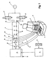
- Fig. 1 shown vehicle seat 10, for example, in the backrest four formed as air cushion forming elements 11 and in the seat, for example, two also formed as air cushion forming elements 11 integrated.
- the fluid volume in the deformation elements 11, so the air filling of the air cushion can be modified to adapt on the one hand the seat contour to the individual wishes of the seat occupant or on the other hand to perform a massage of the seat occupant.
- Fluid is understood here to mean any flowing medium, ie liquids as well as air or other gases. Usually, however, compressed air is preferably used.
- the deformation elements 11, in this case air cushions perform a pre-stroke by filling (inflating) in a fixed, temporal sequence and a return stroke by emptying (venting).
- the sequence program is stored in a microcomputer 12 and can be accessed via a keyboard 15 of the seat user.
- the microcomputer 12 drives a control member which is disposed between a fluid pressure source 13 and the leads 14 to the strain elements 11.
- the fluid pressure source 13 is an air pressure source, such as a compressor with compressed air reservoir
- the control member is a pneumatic control member.
- the control member is designed as a slide valve 16. It comprises a housing 17 with connection openings 18 for in each case one supply line 14 to one of the deformation elements 11 and a control spool 19 adjustable in the housing 17.
- the spool 19 has at least one control opening 20 cooperating with the connection openings 18 in the housing 17 and at least one in the control opening 20 opening connecting channel 21, which is acted upon by fluid from the fluid pressure source 13.
- the control port 20 can be aligned with a selected port 18, so that a connection between the fluid pressure source 13 and the to a deformation element 11th leading supply line 14 is made.
- a selected port 18 are in the embodiment according to Fig.
- connection openings 18 are opened in the housing 17, and thus the connected deformation elements 11 emptied, while in another embodiment, the remaining connection openings 18 are closed by the spool 19 fluid-tight, so that the fluid or air pressure is maintained in the deformation elements 11.
- the spool 19 is designed as axial slide 22. It comprises a slide head 23 containing the control opening 20 and the connection channel 21 and a slide rod 24 rigidly connected to the slide head 23.
- the slide rod 24 is coupled to a motor drive 25, for example a linear stepping motor.
- the slide head 23, which is axially displaceable in the elongated, rectangular housing 17, is sealed in the region of the control opening 20 by means of a ring seal 28 enclosing it, with respect to the housing wall 171 containing the connection openings 18.
- the connection openings 18 are lined up in the sliding direction of the slide head 23 at a distance one behind the other.
- connection openings 18 are divided into two groups with the same number of connection openings 18.
- the connection openings 18 in the sliding direction of the slide head 23 are arranged one behind the other, wherein the two rows formed by the two groups are aligned parallel to each other.
- the slide head 23 has two separate control openings 20 with connection channel 21, of which in each case a control opening 20 is assigned to a row of the connection openings 18.
- Each connection channel 21 is connected to the fluid pressure source 13 via a separate connecting line 26.
- a 3/2-way solenoid valve 27 is arranged, via which the associated connection channel 21 connected to the fluid pressure source 13 or connected to a discharge line, that is vented, can be.
- connection openings 20 in the slide head 23 and their assignment to the two rows of connection openings 18 is made such that in each case one connection opening 18 from each row is aligned with the associated control opening 20 at the same time, while the remaining connection openings 18 are opened and thus the deformation elements 11 connected to them are emptied are.
- both connection channels 21 are relieved. If both 3/2-way solenoid valves 27 are switched over, both control openings 20 are simultaneously connected to the fluid pressure source 13. By selectively switching one or the other 3/2-Wegemangetventils 27, the two control ports 20 can be connected sequentially to the fluid pressure source 13.
- the slide head 23 is moved with the control openings 20 into different setting positions. In each setting position, at least one deformation element 11 is filled (ventilated), while a previously filled deformation element 11 is emptied (vented) by changing the slide head position again. If the deformation elements 11 are activated in a specific sequence, then these lead to a forward stroke and subsequently to a return stroke, which leads to a massage effect in the seat user.
Landscapes
- Engineering & Computer Science (AREA)
- Mechanical Engineering (AREA)
- General Engineering & Computer Science (AREA)
- Aviation & Aerospace Engineering (AREA)
- Transportation (AREA)
- Seats For Vehicles (AREA)
- Massaging Devices (AREA)
- Multiple-Way Valves (AREA)
- Mattresses And Other Support Structures For Chairs And Beds (AREA)
- Chair Legs, Seat Parts, And Backrests (AREA)
Description
- Die Erfindung betrifft eine Vorrichtung zur Steuerung des Fluidvolumens in Formänderungselementen von Sitzen, insbesondere Fahrzeugsitzen, gemäß dem Oberbegriff des Anspruchs 1.
- Solche Formänderungselemente in Sitzen, auch Sitzeinlagen genannt, dienen der Verbesserung des Sitzkomforts durch individuelle Anpassung der Sitzkonturen des Sitzes an den Sitzbenutzer und werden bei sog. Multikonturlehnen in Fahrzeugsitzen auch zur Massage des Sitzbenutzers herangezogen.
- Bei einem bekannten Fahrzeugsitz (
DE 100 63 478 A1 beinhaltet auch die Merkmale des Oberbegriffs des Anspruchs 1) werden mehrere als Luftkissen ausgeführte Formänderungselemente von einer Steuervorrichtung über ein pneumatisches Steuerglied zeitlich versetzt angesteuert und führen zur Massage einer den Sitz benutzenden Person einen Vorhub durch Befüllen mit Druckluft und einen Rückhub durch Entlüften aus. Die Befüllung und Entlüftung der Luftkissen erfolgt mittels elektromagnetischer Ventile, wobei die Luftkissen zu Kissengruppen zusammengefasst sind und in jeder von einer Druckluftquelle zu einer Kissengruppe führenden Druckluftleitung die Reihenschaltung eines 3/2-Wegemagnetventils und eines 2/2-Wegemagnetventils angeordnet ist. Üblicherweise werden die Ventile zu Ventilblöcken zusammengefasst montiert. Solche Ventilblöcke sind schwer und großvolumig und im Sitz selbst relativ schwierig zu integrieren. - Bei einer bekannten Vorrichtung dieser Art (
DE 31 42 833 A1 ) weist das Schieberventil als Steuerschieber einen Drehschieber auf, der eine zentralen Druckraum enthält, dem das Medium von einem Druckmodulator ausgehend zugeführt wird. Dieser Drehschieber ist etwa topfförmig und enthält in der Seitenwandung einen radialen, nach außen hin offenen Kanal. In diesem Bereich sitzt auf der Außenfläche der Wandung des Drehschiebers ein Dichtring mit zentralem Durchgangskanal, der mit dem Kanal des Drehschiebers fluchtet. Der Drehschieber ist innerhalb eines etwa topfförmigen Gehäuses drehverstellbar. Das topfförmige Gehäuse weist in Umfangsrichtung beabstandete innere radiale Kanäle auf, die in Axialkanäle mit Anschlussöffnungen für Leitungen übergehen. Die inneren Kanäle befinden sich axial auf Höhe des einen radialen Kanals des Drehschiebers. Der Drehschieber kann in drei verschiedene Drehstellungen gedreht werden, wobei dann jeweils dessen Kanal über den Durchgangskanal im Dichtring mit einem inneren Kanal des Gehäuses in Verbindung gelangt, so dass im zentralen Druckraum befindliches Fluid über diese Kanalverbindung in die jeweilige Leitung zu dem jeweiligen Formänderungselement gelangen kann. Auch eine solche Vorrichtung, die mit einem Druckmodulator zu einer Baueinheit vereinigt ist, baut groß und schwer und benötigt viel Platz. - Der Erfindung liegt die Aufgabe zugrunde, eine Vorrichtung zur Steuerung des Fluidvolumens der eingangs genannten Art anzugeben, die bei gleicher Funktionalität ein kleineres Bauvolumen und Baugewicht aufweist.
- Die Aufgabe ist erfindungsgemäß durch die Merkmale des Anspruchs 1 gelöst.
- Die erfindungsgemäße Vorrichtung zur Steuerung des Fluidvolumens in Formänderungselementen von Sitzen hat den Vorteil, dass durch die Ausbildung des Steuerglieds als Schieberventil mit einem Steuerschieber in Form eines Axialschiebers, der mindestens eine mit Fluid beaufschlagbare Steueröffnung mit jeweils einer der Anschlussöffnungen in Fluidverbindung bringt, auf einfache Weise eine beliebige Ansteuerung der einzelnen Formänderungselemente realisiert werden kann. Das Schieberventil lässt sich bei gleichem Funktionsumfang kleiner und leichtgewichtiger ausführen und konstruktiv vorteilhaft in den Sitz integrieren. Das Schieberventil kann mit mehreren parallelen Steueröffnungen ausgeführt werden, wobei jeweils eine Steueröffnung einer bestimmten Anzahl von Anschlussöffnungen zugeordnet ist. Durch Vorsehen eines zusätzlichen Schaltventils ist es möglich, eine Mehrzahl von Formänderungselementen im Sitz gleichzeitig oder zeitlich nacheinander mit Fluid zu befüllen oder zu entleeren.
- Vorteilhafte Ausführungsformen der erfindungsgemäßen Vorrichtung zur Steuerung des Fluidvolumens mit zweckmäßigen Weiterbildungen und Ausgestaltungen der Erfindung sind in den weiteren Ansprüchen angegeben.
- Die Erfindung ist anhand eines in der Zeichnung dargestellten Ausführungsbeispieles im folgenden näher beschrieben. Es zeigen jeweils in schematischer Darstellung :
- Fig. 1
- eine perspektivische Darstellung eines Fahrzeugsitzes mit einer Steuerungsvorrichtung für das Fluidvolumen in Formänderungselementen des Fahrzeugsitzes,
- Fig. 2
- einen Schnitt längs der Linie II - II in
Fig. 1 eines Schieberventils der Steuerungsvorrichtung. - Bei dem in
Fig. 1 gezeigten Fahrzeugsitz 10 sind beispielsweise in der Rückenlehne vier als Luftkissen ausgebildete Formänderungselemente 11 und in der Sitzfläche beispielsweise zwei ebenfalls als Luftkissen ausgebildete Formänderungselemente 11 integriert. Mittels einer inFig. 1 schematisch dargestellten Steuerungsvorrichtung kann das Fluidvolumen in den Formänderungselementen 11, also die Luftfüllung der Luftkissen, modifiziert werden, um einerseits die Sitzkontur an die individuellen Wünsche des Sitzbenutzers anzupassen oder andererseits eine Massage des Sitzbenutzers durchzuführen. Unter Fluid wird hier jedes strömende Medium verstanden, also neben Luft oder anderen Gasen auch Flüssigkeiten. Üblicherweise wird aber bevorzugt Druckluft eingesetzt. Im Massagefall führen die Formänderungselemente 11, hier Luftkissen, in einem festgelegten, zeitlichen Ablauf durch Auffüllen (Aufblasen) einen Vorhub und durch Entleeren (Entlüften) einen Rückhub aus. Das Ablaufprogramm ist in einem Mikrocomputer 12 abgespeichert und kann über eine Tastatur 15 von dem Sitzbenutzer aufgerufen werden. Der Mikrocomputer 12 steuert ein Steuerglied an, das zwischen einer Fluiddruckquelle 13 und den Zuleitungen 14 zu den Formänderungselementen 11 angeordnet ist. Im Falle der Luftkissenausbildung der Formänderungselemente 11 ist die Fluiddruckquelle 13 eine Luftdruckquelle, z.B. ein Kompressor mit Druckluftspeicher, und das Steuerglied ein pneumatisches Steuerglied. - Das Steuerglied ist als Schieberventil 16 ausgebildet. Es umfasst ein Gehäuse 17 mit Anschlussöffnungen 18 für jeweils eine Zuleitung 14 zu einem der Formänderungselemente 11 und einen im Gehäuse 17 verstellbaren Steuerschieber 19. Der Steuerschieber 19 weist mindestens eine mit den Anschlussöffnungen 18 im Gehäuse 17 zusammenwirkende Steueröffnung 20 und mindestens einen in der Steueröffnung 20 mündenden Anschlusskanal 21 auf, der mit Fluid aus der Fluiddruckquelle 13 beaufschlagbar ist. Durch Verstellen des Steuerschiebers 19 kann die Steueröffnung 20 mit einer ausgewählten Anschlussöffnung 18 fluchtend ausgerichtet werden, so dass eine Verbindung zwischen der Fluiddruckquelle 13 und der zu einem Formänderungselement 11 führenden Zuleitung 14 hergestellt ist. Während der fluchtenden Ausrichtung der Steueröffnung 20 mit einer ausgewählten Anschlussöffnung 18 sind bei dem Ausführungsbeispiel gemäß
Fig. 1 und2 die übrigen Anschlussöffnungen 18 im Gehäuse 17 geöffnet, und damit die angeschlossenen Formänderungselemente 11 entleert, während bei einem weiteren Ausführungsbeispiel die übrigen Anschlussöffnungen 18 durch den Steuerschieber 19 fluiddicht abgeschlossen sind, so dass der Fluid- bzw. Luftdruck in den Formänderungselementen 11 gehalten wird. - Im Ausführungsbeispiel der
Fig. 1 und2 ist der Steuerschieber 19 als Axialschieber 22 ausgebildet. Er umfasst einen die Steueröffnung 20 und den Anschlusskanal 21 enthaltenden Schieberkopf 23 und eine mit dem Schieberkopf 23 starr verbundene Schieberstange 24. Die Schieberstange 24 ist mit einem motorischen Antrieb 25, z.B. einen linearen Schrittmotor, gekoppelt. Der in dem langgestreckten, rechteckförmigen Gehäuse 17 axial verschiebbare Schieberkopf 23 ist im Bereich der Steueröffnung 20 mittels einer diese umschließenden Ringdichtung 28 gegenüber der die Anschlussöffnungen 18 enthaltenden Gehäusewand 171 abgedichtet. Die Anschlussöffnungen 18 sind in Schieberichtung des Schieberkopfes 23 im Abstand hintereinander aufgereiht. Im Ausführungsbeispiel derFig. 1 und2 sind die Anschlussöffnungen 18 in zwei Gruppen mit gleicher Anzahl von Anschlussöffnungen 18 aufgeteilt. In jeder Gruppe sind die Anschlussöffnungen 18 in Schieberichtung des Schieberkopfes 23 hintereinander angeordnet, wobei die von den beiden Gruppen gebildeten zwei Reihen parallel zueinander ausgerichtet sind. Der Schieberkopf 23 weist zwei getrennte Steueröffnungen 20 mit Anschlusskanal 21 auf, von denen jeweils eine Steueröffnung 20 einer Reihe der Anschlussöffnungen 18 zugeordnet ist. Jeder Anschlusskanal 21 ist über eine separate Anschlussleitung 26 mit der Fluiddruckquelle 13 verbunden. In jeder Anschlussleitung 26 ist ein 3/2-Wegemagnetventil 27 angeordnet, über das der zugeordnete Anschlusskanal 21 mit der Fluiddruckquelle 13 verbunden oder an eine Entlastungsleitung angeschlossen, also entlüftet, werden kann. Die Anordnung der beiden Steueröffnungen 20 im Schieberkopf 23 und deren Zuordnung zu den beiden Reihen von Anschlussöffnungen 18 ist so getroffen, dass jeweils eine Anschlussöffnung 18 aus jeder Reihe gleichzeitig mit der zugeordneten Steueröffnung 20 fluchtet, während die übrigen Anschlussöffnungen 18 geöffnet und damit die an ihnen angeschlossenen Formänderungselemente 11 entleert sind. In der inFig. 1 gezeigten Stellung der beiden 3/2-Wegemangetventile 27 sind beide Anschlusskanäle 21 entlastet. Werden beide 3/2-Wegemagnetventile 27 umgeschaltet, sind beide Steueröffnungen 20 gleichzeitig an die Fluiddruckquelle 13 angeschlossen. Durch wahlweises Umschalten des einen oder anderen 3/2-Wegemangetventils 27 können die beiden Steueröffnungen 20 zeitlich nacheinander an die Fluiddruckquelle 13 angeschlossen werden. - Wird nunmehr der motorische Antrieb 25 für den Axialschieber 22 nach einem bestimmten Programm von dem Mikrocomputer 12 angesteuert, so wird der Schieberkopf 23 mit den Steueröffnungen 20 in verschiedene Stellpositionen verfahren. In jeder Stellposition wird mindestens ein Formänderungselement 11 befüllt (belüftet), während ein zuvor befülltes Formänderungselement 11 durch Veränderung der Schieberkopfposition wieder entleert (entlüftet) wird. Werden die Formänderungselemente 11 in einer bestimmten Reihenfolge angesteuert, so führen diese einen Vorhub und anschließend einen Rückhub auf, was zu einer Massagewirkung beim Sitzbenutzer führt.
Claims (8)
- Vorrichtung zur Steuerung des Fluidvolumens in Formänderungselementen (11) von Sitzen, insbesondere Fahrzeugsitzen (10), mit einem einerseits mit einer Fluiddruckquelle (13) und andererseits mit den Formänderungselementen (11) verbundenen, zum Auffüllen der Formänderungselemente (11) mit Fluid und Ablassen von Fluid aus den Formänderungselementen (11) dienenden Schieberventil (16), das ein Gehäuse (17) mit Anschlussöffnungen (18) für jeweils ein Formänderungselement (11) und einen im Gehäuse (17) relativ zu den Anschlussöffnungen (18) verstellbaren Steuerschieber (19) aufweist, der mindestens eine mit den Anschlussöffnungen (18) zusammenwirkende Steueröffnung (20) und mindestens einen in die Steueröffnung (20) mündenden, mit Fluid aus der Fluiddruckquelle (13) beaufschlagbaren Anschlusskanal (21) aufweist, dadurch gekennzeichnet, dass der Steuerschieber (19) ein im Gehäuse (17) geführter Axialschieber (22) ist, der einen die mindestens eine Steueröffnung (20) und den mindestens einen Anschlusskanal (21) enthaltenden, axial verschiebbaren Schieberkopf (23) und eine mit dem Schieberkopf (23) starr verbundene Schieberstange (24) zur Axialverschiebung des Schieberkopfes (23) aufweist, und dass die Anschlussöffnungen (18) in Schieberichtung des Schieberkopfes (23) in Abstand hintereinander aufgereiht sind.
- Vorrichtung nach Anspruch 1, dadurch gekennzeichnet, dass die Anschlussöffnungen (18) in mindestens zwei Gruppen von in Verschieberichtung des Steuerschiebers (19) hintereinander angeordneten Anschlussöffnungen (18) aufgeteilt sind und dass der Steuerschieber (19) eine der Anzahl der Gruppen entsprechende Zahl von separaten Steueröffnungen (20) mit zugeordnetem Anschlusskanal (21) aufweist, von denen jeweils eine Steueröffnung (20) einer Gruppe von Anschlussöffnungen (18) zugeordnet ist.
- Vorrichtung nach Anspruch 1 oder 2, dadurch gekennzeichnet, dass der Schieberkopf (23) zumindest im Bereich um die Steueröffnung (20) gegenüber der die Anschlussöffnungen (18) enthaltenen Gehäusewand (171) abgedichtet ist.
- Vorrichtung nach einem der Ansprüche 1 bis 3, dadurch gekennzeichnet, dass die Schieberstange (24) mit einem vorzugsweise motorischen Antrieb (25) gekoppelt ist.
- Vorrichtung nach Anspruch 4, dadurch gekennzeichnet, dass der Antrieb (25) als Schrittmotor ausgebildet ist.
- Vorrichtung nach einem der Ansprüche 1 bis 5, dadurch gekennzeichnet, dass das Gehäuse (17) langgestreckt, vorzugsweise rechteckig, ist.
- Vorrichtung nach einem der Ansprüche 1 bis 6, dadurch gekennzeichnet, dass der Anschlusskanal (21) über ein Schaltventil (27) mit der Fluiddruckquelle (13) verbunden ist.
- Vorrichtung nach einem der Ansprüche 1 bis 7, dadurch gekennzeichnet, dass die Anschlussöffnungen (18) mit Anschlussstutzen zum Aufschieben von zu den Formänderungselementen (11) führenden Zuleitungen (14) versehen sind.
Applications Claiming Priority (2)
| Application Number | Priority Date | Filing Date | Title |
|---|---|---|---|
| DE2003144974 DE10344974B3 (de) | 2003-09-27 | 2003-09-27 | Vorrichtung zur Steuerung des Fluidvolumens in Formänderungselementen von Sitzen |
| DE10344974 | 2003-09-27 |
Publications (3)
| Publication Number | Publication Date |
|---|---|
| EP1518749A2 EP1518749A2 (de) | 2005-03-30 |
| EP1518749A3 EP1518749A3 (de) | 2007-05-02 |
| EP1518749B1 true EP1518749B1 (de) | 2008-06-18 |
Family
ID=34042284
Family Applications (1)
| Application Number | Title | Priority Date | Filing Date |
|---|---|---|---|
| EP20040019352 Expired - Lifetime EP1518749B1 (de) | 2003-09-27 | 2004-08-14 | Vorrichtung zur Steuerung des Fluidvolumens in Formänderungselementen von Sitzen |
Country Status (4)
| Country | Link |
|---|---|
| US (1) | US7267404B2 (de) |
| EP (1) | EP1518749B1 (de) |
| JP (1) | JP2005103261A (de) |
| DE (2) | DE10344974B3 (de) |
Cited By (1)
| Publication number | Priority date | Publication date | Assignee | Title |
|---|---|---|---|---|
| DE102012224449A1 (de) * | 2012-12-27 | 2014-07-03 | Robert Bosch Gmbh | Sitzvorrichtung |
Families Citing this family (35)
| Publication number | Priority date | Publication date | Assignee | Title |
|---|---|---|---|---|
| DE602004024276D1 (de) * | 2003-10-21 | 2010-01-07 | Ts Tech Co Ltd | Fahrzeugsitz mit System zum Ermöglichen von Abbau der Müdigkeit von der im Sitz sitzenden Person |
| US7681593B1 (en) * | 2004-12-13 | 2010-03-23 | Horvat Branimir L | Sequential distributor of gases and liquids |
| DE102006012377B4 (de) * | 2006-03-17 | 2021-09-23 | Bayerische Motoren Werke Aktiengesellschaft | Konturverstellbarer Fahrzeugsitz mit einer Rückenlehne |
| DE102006015523A1 (de) * | 2006-03-31 | 2007-10-04 | Recaro Aircraft Seating Gmbh & Co. Kg | Sitzvorrichtung |
| DE102008015763B4 (de) | 2007-07-02 | 2018-08-02 | Conti Temic Microelectronic Gmbh | Vorrichtung zur Be-/Entlüftung einer Mehrzahl von pneumatischen Aktuatoren, Sitz und Fahrzeug mit einer derartigen Vorrichtung |
| US8162398B2 (en) * | 2009-03-26 | 2012-04-24 | Schukra of North America Co. | Zone lumbar massage system |
| EP2361800B1 (de) * | 2010-02-17 | 2013-04-24 | L & P Swiss Holding AG | Einstellvorrichtung für einen Sitz und Verfahren zur Bedienung der Einstellvorrichtung |
| DE102011107677B4 (de) * | 2011-07-13 | 2013-12-05 | Faurecia Autositze Gmbh | Fahrzeugsitz |
| WO2013170335A1 (en) * | 2012-05-16 | 2013-11-21 | Schukra of North America Co. | System and method for a pressure signal linearization transfer function |
| US9086189B2 (en) | 2012-05-16 | 2015-07-21 | Leggett & Platt Canada Co. | System and method for a pressure signal linearization transfer function |
| DE102012209449A1 (de) * | 2012-06-05 | 2013-12-05 | Conti Temic Microelectronic Gmbh | Verfahren und Vorrichtung zum Befüllen und Entleeren eines Sitzkissens |
| DE102012212686B4 (de) * | 2012-07-19 | 2016-11-10 | Alfmeier Präzision AG Baugruppen und Systemlösungen | Ventil |
| EP2769878B1 (de) * | 2013-02-20 | 2015-03-25 | Schukra Gerätebau GmbH | Sitzeinstellvorrichtung und Verfahren zur Sitzeinstellung |
| US9097365B2 (en) * | 2013-03-15 | 2015-08-04 | Alps Electric Co., Ltd. | Micro-valve assembly |
| DE102013220563A1 (de) * | 2013-10-11 | 2015-04-16 | Conti Temic Microelectronic Gmbh | Vorrichtung zum pneumatischen Befüllen und Entleeren von Blasen in einem Sitz eines Verkehrsmittels |
| US9987961B2 (en) | 2014-06-09 | 2018-06-05 | Lear Corporation | Adjustable seat assembly |
| US10328823B2 (en) | 2014-06-09 | 2019-06-25 | Lear Corporation | Adjustable seat assembly |
| WO2016141501A1 (zh) * | 2015-03-12 | 2016-09-15 | 惠州市唐群电子有限公司 | 座椅腰托的渐进式调整系统 |
| DE202015009848U1 (de) * | 2015-04-09 | 2020-09-21 | Alfmeier Präzision SE | Vorrichtung zur Einstellung einer Kontur eines Fahrzeugsitzes mit Konturverstellung |
| US9884570B2 (en) | 2015-05-19 | 2018-02-06 | Lear Corporation | Adjustable seat assembly |
| US9845026B2 (en) | 2015-05-19 | 2017-12-19 | Lear Corporation | Adjustable seat assembly |
| WO2017011391A1 (en) * | 2015-07-10 | 2017-01-19 | Kongsberg Automotive, Inc. | Lumbar support system for a vehicle seat assembly |
| US9661928B2 (en) | 2015-09-29 | 2017-05-30 | Lear Corporation | Air bladder assembly for seat bottoms of seat assemblies |
| DE102015219197B4 (de) | 2015-10-05 | 2019-07-04 | Conti Temic Microelectronic Gmbh | Pneumatisches Magnetventil |
| US9827888B2 (en) | 2016-01-04 | 2017-11-28 | Lear Corporation | Seat assemblies with adjustable side bolster actuators |
| DE102016209872A1 (de) | 2016-06-06 | 2017-12-07 | Continental Automotive Gmbh | Fahrzeugbordnetz mit Wechselrichter, Energiespeicher, elektrischer Maschine und Wechselstrom-Übertragungsanschluss |
| DE102016212586A1 (de) * | 2016-07-11 | 2018-01-11 | Conti Temic Microelectronic Gmbh | Pneumatische Vorrichtung |
| DE102016214529B4 (de) * | 2016-08-05 | 2023-06-07 | Conti Temic Microelectronic Gmbh | Verfahren zur Herstellung einer mit Druckmittel befüllbaren Blase als Stellelement für einen Sitz |
| US10363852B2 (en) * | 2016-09-15 | 2019-07-30 | Ford Global Technologies, Llc | Apparatus and method for customizing a vehicle seat |
| US10286815B2 (en) * | 2017-04-03 | 2019-05-14 | Ford Global Technologies, Llc | H-point lift options for sleeper seats |
| US20180345823A1 (en) | 2017-06-01 | 2018-12-06 | Lear Corporation | Seat assembly adjustment patterns |
| US10525854B2 (en) * | 2018-01-02 | 2020-01-07 | Dowco, Inc. | Adjustable seat |
| CN120436944A (zh) * | 2024-02-06 | 2025-08-08 | 科际精密股份有限公司 | 脉动控制方法及脉动控制装置 |
| KR20250156963A (ko) * | 2024-04-26 | 2025-11-04 | 현대트랜시스 주식회사 | 차량 시트용 공압 제어기 |
| CN120557274B (zh) * | 2025-07-05 | 2025-11-18 | 广东安昂智能制造供应链技术有限公司 | 一种直线轴承滑动机构 |
Family Cites Families (14)
| Publication number | Priority date | Publication date | Assignee | Title |
|---|---|---|---|---|
| GB1410398A (en) * | 1973-09-29 | 1975-10-15 | Martonair Ltd | Slide valve |
| US4136853A (en) * | 1975-02-24 | 1979-01-30 | Atlas Copco Aktiebolag | Slide valve |
| US4000685A (en) * | 1975-05-05 | 1977-01-04 | Montalvo Jr Edwin J | Push/pull valve for two or three way operation |
| JPS57136413A (en) * | 1981-02-19 | 1982-08-23 | Aisin Seiki | Air supply and discharge system of air lumber support |
| US4491157A (en) * | 1981-03-06 | 1985-01-01 | Aisin Seiki Kabushiki Kaisha | Valve assembly for air bag control |
| DE3142833C2 (de) * | 1981-10-29 | 1986-04-24 | Daimler-Benz Ag, 7000 Stuttgart | Pneumatische Einrichtung zur Druckbeaufschlagung mehrerer ansteuerbarer Druckkammern |
| JPS58160679A (ja) * | 1982-03-18 | 1983-09-24 | Aisin Seiki Co Ltd | エアランバ−サポ−トバルブ |
| GB8326702D0 (en) * | 1983-10-06 | 1983-11-09 | Brisland M J | Slide valve |
| DE8334946U1 (de) * | 1983-12-06 | 1984-04-05 | Hauke, Günther, Dipl.-Ing. (FH) | Steuervorrichtung fuer pneumatische systeme mit mindestens zwei aufblasbaren luftkammern in sitzen oder liegen |
| US5135282A (en) * | 1989-08-18 | 1992-08-04 | Man Nutzfahrzeuge Aktiengesellschaft | Motor vehicle seat back |
| US6203105B1 (en) * | 1999-08-20 | 2001-03-20 | Mccord Winn Textron Inc. | Vehicle impact responsive multiple bladder seating and headrest system and method |
| DE10063478A1 (de) * | 2000-12-20 | 2002-07-04 | Alfmeier Praez Ag | Sitz, insbesondere Fahrzeugsitz |
| WO2002065004A1 (en) * | 2001-01-18 | 2002-08-22 | Roho, Inc. | Valve for zoned cellular cushion |
| US6895988B2 (en) * | 2002-09-10 | 2005-05-24 | Grant Airmass Corporation | Self-actuating control valve for a bed pad or seat pad |
-
2003
- 2003-09-27 DE DE2003144974 patent/DE10344974B3/de not_active Expired - Fee Related
-
2004
- 2004-08-14 DE DE200450007380 patent/DE502004007380D1/de not_active Expired - Lifetime
- 2004-08-14 EP EP20040019352 patent/EP1518749B1/de not_active Expired - Lifetime
- 2004-09-22 JP JP2004274903A patent/JP2005103261A/ja active Pending
- 2004-09-22 US US10/947,462 patent/US7267404B2/en not_active Expired - Lifetime
Cited By (1)
| Publication number | Priority date | Publication date | Assignee | Title |
|---|---|---|---|---|
| DE102012224449A1 (de) * | 2012-12-27 | 2014-07-03 | Robert Bosch Gmbh | Sitzvorrichtung |
Also Published As
| Publication number | Publication date |
|---|---|
| EP1518749A3 (de) | 2007-05-02 |
| US7267404B2 (en) | 2007-09-11 |
| DE502004007380D1 (de) | 2008-07-31 |
| US20050067868A1 (en) | 2005-03-31 |
| JP2005103261A (ja) | 2005-04-21 |
| EP1518749A2 (de) | 2005-03-30 |
| DE10344974B3 (de) | 2005-02-10 |
Similar Documents
| Publication | Publication Date | Title |
|---|---|---|
| DE10344974B3 (de) | Vorrichtung zur Steuerung des Fluidvolumens in Formänderungselementen von Sitzen | |
| EP1544155B1 (de) | Füllelement sowie Füllmaschine mit derartigen Füllelementen | |
| DE69722746T2 (de) | Absperr- und Durchflussvorrichtung | |
| DE3205859A1 (de) | Lenden-abstuetzsystem fuer einen fahrzeugsitz | |
| EP0435357B1 (de) | Bypass-Ventil mit abstimmbaren Kennungen für regelbare und steuerbare Schwingungsdämpfer | |
| DE2555156B2 (de) | Hochdruck-Mischkopf | |
| DE2607641B2 (de) | Hochdruck-Mischkopf | |
| DE1480465C3 (de) | Abfederung für Fahrzeugsitze | |
| DE2726502A1 (de) | Vorrichtung zur abgabe von fliessfaehigen stoffen, insbesondere von wuerzen | |
| EP0224774B1 (de) | Progressiv-Verteiler für Schmiermittel | |
| DE3333745A1 (de) | Druckmittel-verteiler | |
| DE102013222132A1 (de) | Mehrkammer-Brausekopf | |
| DE10152561A1 (de) | Rückenlehne für einen Sitz | |
| DE1281281B (de) | Hoehenregelvorrichtung mit Niveauvorwaehlung fuer Fahrzeuge | |
| DE2333941A1 (de) | Gepolsterter sitz | |
| DE2855916C2 (de) | Vorrichtung zum Herstellen eines Reaktionsgemisches aus Schaumstoff oder Massivstoff bildenden, fließfähigen Komponenten | |
| EP0319670A2 (de) | Relaisventileinrichtung | |
| DE10257117B4 (de) | Ventilsystem zum Befüllen und Entlüften von Sitzpolstern, insbesondere in Fahrzeugen | |
| DE2615761B2 (de) | Einrichtung zum Einbringen von staubförmigem Brennstoff in die Zylinder einer Brennkraftmaschine | |
| DE69606589T2 (de) | Druckbehälterventil sowie mit einem solchen Ventil versehener Druckbehälter | |
| EP0640429B1 (de) | Pneumatikantrieb, insbesondere für die Betätigung von Schweisselektroden | |
| DE2263097C3 (de) | Hydropneumatisches Federbein mit innerer Niveauregelung zum Anschluß an eine außen liegende Durckquelle für Kraftfahrzeuge | |
| DE3326793C2 (de) | Schieberventil mit zwei in der zylindrischen Bohrung eines Ventilgehäuses axial versetzt gegeneinander angeordneten Kolben | |
| DE2262730C3 (de) | Vorrichtung zum dosierten Zuführen einer flüssigen Kunststoffkomponente in eine Mischkammer | |
| WO1994008493A1 (de) | Sitzmöbel mit luftzellen |
Legal Events
| Date | Code | Title | Description |
|---|---|---|---|
| PUAI | Public reference made under article 153(3) epc to a published international application that has entered the european phase |
Free format text: ORIGINAL CODE: 0009012 |
|
| AK | Designated contracting states |
Kind code of ref document: A2 Designated state(s): AT BE BG CH CY CZ DE DK EE ES FI FR GB GR HU IE IT LI LU MC NL PL PT RO SE SI SK TR |
|
| AX | Request for extension of the european patent |
Extension state: AL HR LT LV MK |
|
| PUAL | Search report despatched |
Free format text: ORIGINAL CODE: 0009013 |
|
| RAP1 | Party data changed (applicant data changed or rights of an application transferred) |
Owner name: DAIMLERCHRYSLER AG Owner name: ALFMEIER PRAEZISION AG BAUGRUPPEN UND SYSTEMLOESUN |
|
| AK | Designated contracting states |
Kind code of ref document: A3 Designated state(s): AT BE BG CH CY CZ DE DK EE ES FI FR GB GR HU IE IT LI LU MC NL PL PT RO SE SI SK TR |
|
| AX | Request for extension of the european patent |
Extension state: AL HR LT LV MK |
|
| RAP1 | Party data changed (applicant data changed or rights of an application transferred) |
Owner name: ALFMEIER PRAEZISION AG BAUGRUPPEN UND SYSTEMLOESUN |
|
| 17P | Request for examination filed |
Effective date: 20070609 |
|
| GRAP | Despatch of communication of intention to grant a patent |
Free format text: ORIGINAL CODE: EPIDOSNIGR1 |
|
| RTI1 | Title (correction) |
Free format text: DEVICE FOR CONTROLLING THE FLUID VOLUME IN SHAPE ADJUSTMENT ELEMENTS OF SEATS |
|
| GRAS | Grant fee paid |
Free format text: ORIGINAL CODE: EPIDOSNIGR3 |
|
| AKX | Designation fees paid |
Designated state(s): DE FR GB |
|
| GRAA | (expected) grant |
Free format text: ORIGINAL CODE: 0009210 |
|
| AK | Designated contracting states |
Kind code of ref document: B1 Designated state(s): DE FR GB |
|
| REG | Reference to a national code |
Ref country code: GB Ref legal event code: FG4D Free format text: NOT ENGLISH |
|
| REF | Corresponds to: |
Ref document number: 502004007380 Country of ref document: DE Date of ref document: 20080731 Kind code of ref document: P |
|
| PLBE | No opposition filed within time limit |
Free format text: ORIGINAL CODE: 0009261 |
|
| STAA | Information on the status of an ep patent application or granted ep patent |
Free format text: STATUS: NO OPPOSITION FILED WITHIN TIME LIMIT |
|
| 26N | No opposition filed |
Effective date: 20090319 |
|
| PGFP | Annual fee paid to national office [announced via postgrant information from national office to epo] |
Ref country code: FR Payment date: 20110829 Year of fee payment: 8 Ref country code: GB Payment date: 20110824 Year of fee payment: 8 |
|
| REG | Reference to a national code |
Ref country code: DE Ref legal event code: R082 Ref document number: 502004007380 Country of ref document: DE Representative=s name: MOERTEL, ALFRED, DIPL.-PHYS. DR.RER.NAT., DE Ref country code: DE Ref legal event code: R082 Ref document number: 502004007380 Country of ref document: DE Representative=s name: MEISSNER BOLTE & PARTNER GBR, DE Ref country code: DE Ref legal event code: R082 Ref document number: 502004007380 Country of ref document: DE Representative=s name: MEISSNER BOLTE PATENTANWAELTE RECHTSANWAELTE P, DE |
|
| GBPC | Gb: european patent ceased through non-payment of renewal fee |
Effective date: 20120814 |
|
| REG | Reference to a national code |
Ref country code: FR Ref legal event code: ST Effective date: 20130430 |
|
| PG25 | Lapsed in a contracting state [announced via postgrant information from national office to epo] |
Ref country code: GB Free format text: LAPSE BECAUSE OF NON-PAYMENT OF DUE FEES Effective date: 20120814 |
|
| PG25 | Lapsed in a contracting state [announced via postgrant information from national office to epo] |
Ref country code: FR Free format text: LAPSE BECAUSE OF NON-PAYMENT OF DUE FEES Effective date: 20120831 |
|
| REG | Reference to a national code |
Ref country code: DE Ref legal event code: R082 Ref document number: 502004007380 Country of ref document: DE Representative=s name: MEISSNER BOLTE & PARTNER GBR, DE Ref country code: DE Ref legal event code: R082 Ref document number: 502004007380 Country of ref document: DE Representative=s name: MEISSNER BOLTE PATENTANWAELTE RECHTSANWAELTE P, DE |
|
| REG | Reference to a national code |
Ref country code: DE Ref legal event code: R082 Ref document number: 502004007380 Country of ref document: DE Representative=s name: MEISSNER BOLTE PATENTANWAELTE RECHTSANWAELTE P, DE |
|
| REG | Reference to a national code |
Ref country code: DE Ref legal event code: R079 Ref document number: 502004007380 Country of ref document: DE Free format text: PREVIOUS MAIN CLASS: B60N0002440000 Ipc: B60N0002900000 |
|
| PGFP | Annual fee paid to national office [announced via postgrant information from national office to epo] |
Ref country code: DE Payment date: 20180827 Year of fee payment: 15 |
|
| REG | Reference to a national code |
Ref country code: DE Ref legal event code: R119 Ref document number: 502004007380 Country of ref document: DE |
|
| PG25 | Lapsed in a contracting state [announced via postgrant information from national office to epo] |
Ref country code: DE Free format text: LAPSE BECAUSE OF NON-PAYMENT OF DUE FEES Effective date: 20200303 |