EP1518722B1 - System und Verfahren zur Regelung einer Fahrzeugaufhängung - Google Patents
System und Verfahren zur Regelung einer Fahrzeugaufhängung Download PDFInfo
- Publication number
- EP1518722B1 EP1518722B1 EP04022941A EP04022941A EP1518722B1 EP 1518722 B1 EP1518722 B1 EP 1518722B1 EP 04022941 A EP04022941 A EP 04022941A EP 04022941 A EP04022941 A EP 04022941A EP 1518722 B1 EP1518722 B1 EP 1518722B1
- Authority
- EP
- European Patent Office
- Prior art keywords
- vehicle
- corner
- suspension
- road surface
- degree
- Prior art date
- Legal status (The legal status is an assumption and is not a legal conclusion. Google has not performed a legal analysis and makes no representation as to the accuracy of the status listed.)
- Expired - Lifetime
Links
- 239000000725 suspension Substances 0.000 title claims abstract description 211
- 238000000034 method Methods 0.000 title claims description 27
- 238000013016 damping Methods 0.000 claims abstract description 317
- 238000013459 approach Methods 0.000 claims abstract description 27
- 239000000284 extract Substances 0.000 claims description 2
- 230000001133 acceleration Effects 0.000 description 78
- 230000009467 reduction Effects 0.000 description 21
- 238000001514 detection method Methods 0.000 description 9
- 230000008569 process Effects 0.000 description 9
- 230000007423 decrease Effects 0.000 description 8
- 238000012937 correction Methods 0.000 description 6
- 230000007935 neutral effect Effects 0.000 description 6
- 230000035807 sensation Effects 0.000 description 6
- 238000012545 processing Methods 0.000 description 4
- 230000001788 irregular Effects 0.000 description 3
- 238000005070 sampling Methods 0.000 description 3
- 230000003247 decreasing effect Effects 0.000 description 2
- 238000010586 diagram Methods 0.000 description 2
- 230000000694 effects Effects 0.000 description 2
- 230000006870 function Effects 0.000 description 2
- 238000003384 imaging method Methods 0.000 description 2
- 238000012986 modification Methods 0.000 description 2
- 230000004048 modification Effects 0.000 description 2
- 238000012935 Averaging Methods 0.000 description 1
- 239000006096 absorbing agent Substances 0.000 description 1
- 230000005540 biological transmission Effects 0.000 description 1
- 238000004891 communication Methods 0.000 description 1
- 238000010276 construction Methods 0.000 description 1
- 230000008602 contraction Effects 0.000 description 1
- 238000000605 extraction Methods 0.000 description 1
- 230000002349 favourable effect Effects 0.000 description 1
- 230000005484 gravity Effects 0.000 description 1
- 230000000977 initiatory effect Effects 0.000 description 1
- 239000000203 mixture Substances 0.000 description 1
- 238000005192 partition Methods 0.000 description 1
- 230000004044 response Effects 0.000 description 1
- 230000035939 shock Effects 0.000 description 1
- 230000007704 transition Effects 0.000 description 1
Images


Classifications
-
- B—PERFORMING OPERATIONS; TRANSPORTING
- B60—VEHICLES IN GENERAL
- B60G—VEHICLE SUSPENSION ARRANGEMENTS
- B60G17/00—Resilient suspensions having means for adjusting the spring or vibration-damper characteristics, for regulating the distance between a supporting surface and a sprung part of vehicle or for locking suspension during use to meet varying vehicular or surface conditions, e.g. due to speed or load
- B60G17/015—Resilient suspensions having means for adjusting the spring or vibration-damper characteristics, for regulating the distance between a supporting surface and a sprung part of vehicle or for locking suspension during use to meet varying vehicular or surface conditions, e.g. due to speed or load the regulating means comprising electric or electronic elements
- B60G17/016—Resilient suspensions having means for adjusting the spring or vibration-damper characteristics, for regulating the distance between a supporting surface and a sprung part of vehicle or for locking suspension during use to meet varying vehicular or surface conditions, e.g. due to speed or load the regulating means comprising electric or electronic elements characterised by their responsiveness, when the vehicle is travelling, to specific motion, a specific condition, or driver input
- B60G17/0162—Resilient suspensions having means for adjusting the spring or vibration-damper characteristics, for regulating the distance between a supporting surface and a sprung part of vehicle or for locking suspension during use to meet varying vehicular or surface conditions, e.g. due to speed or load the regulating means comprising electric or electronic elements characterised by their responsiveness, when the vehicle is travelling, to specific motion, a specific condition, or driver input mainly during a motion involving steering operation, e.g. cornering, overtaking
-
- B—PERFORMING OPERATIONS; TRANSPORTING
- B60—VEHICLES IN GENERAL
- B60G—VEHICLE SUSPENSION ARRANGEMENTS
- B60G17/00—Resilient suspensions having means for adjusting the spring or vibration-damper characteristics, for regulating the distance between a supporting surface and a sprung part of vehicle or for locking suspension during use to meet varying vehicular or surface conditions, e.g. due to speed or load
- B60G17/015—Resilient suspensions having means for adjusting the spring or vibration-damper characteristics, for regulating the distance between a supporting surface and a sprung part of vehicle or for locking suspension during use to meet varying vehicular or surface conditions, e.g. due to speed or load the regulating means comprising electric or electronic elements
- B60G17/0195—Resilient suspensions having means for adjusting the spring or vibration-damper characteristics, for regulating the distance between a supporting surface and a sprung part of vehicle or for locking suspension during use to meet varying vehicular or surface conditions, e.g. due to speed or load the regulating means comprising electric or electronic elements characterised by the regulation being combined with other vehicle control systems
-
- B—PERFORMING OPERATIONS; TRANSPORTING
- B60—VEHICLES IN GENERAL
- B60G—VEHICLE SUSPENSION ARRANGEMENTS
- B60G17/00—Resilient suspensions having means for adjusting the spring or vibration-damper characteristics, for regulating the distance between a supporting surface and a sprung part of vehicle or for locking suspension during use to meet varying vehicular or surface conditions, e.g. due to speed or load
- B60G17/06—Characteristics of dampers, e.g. mechanical dampers
- B60G17/08—Characteristics of fluid dampers
-
- B—PERFORMING OPERATIONS; TRANSPORTING
- B60—VEHICLES IN GENERAL
- B60G—VEHICLE SUSPENSION ARRANGEMENTS
- B60G2400/00—Indexing codes relating to detected, measured or calculated conditions or factors
- B60G2400/10—Acceleration; Deceleration
- B60G2400/102—Acceleration; Deceleration vertical
-
- B—PERFORMING OPERATIONS; TRANSPORTING
- B60—VEHICLES IN GENERAL
- B60G—VEHICLE SUSPENSION ARRANGEMENTS
- B60G2400/00—Indexing codes relating to detected, measured or calculated conditions or factors
- B60G2400/40—Steering conditions
- B60G2400/41—Steering angle
-
- B—PERFORMING OPERATIONS; TRANSPORTING
- B60—VEHICLES IN GENERAL
- B60G—VEHICLE SUSPENSION ARRANGEMENTS
- B60G2400/00—Indexing codes relating to detected, measured or calculated conditions or factors
- B60G2400/80—Exterior conditions
- B60G2400/82—Ground surface
- B60G2400/821—Uneven, rough road sensing affecting vehicle body vibration
-
- B—PERFORMING OPERATIONS; TRANSPORTING
- B60—VEHICLES IN GENERAL
- B60G—VEHICLE SUSPENSION ARRANGEMENTS
- B60G2400/00—Indexing codes relating to detected, measured or calculated conditions or factors
- B60G2400/80—Exterior conditions
- B60G2400/82—Ground surface
- B60G2400/824—Travel path sensing; Track monitoring
-
- B—PERFORMING OPERATIONS; TRANSPORTING
- B60—VEHICLES IN GENERAL
- B60G—VEHICLE SUSPENSION ARRANGEMENTS
- B60G2401/00—Indexing codes relating to the type of sensors based on the principle of their operation
- B60G2401/16—GPS track data
-
- B—PERFORMING OPERATIONS; TRANSPORTING
- B60—VEHICLES IN GENERAL
- B60G—VEHICLE SUSPENSION ARRANGEMENTS
- B60G2500/00—Indexing codes relating to the regulated action or device
- B60G2500/10—Damping action or damper
-
- B—PERFORMING OPERATIONS; TRANSPORTING
- B60—VEHICLES IN GENERAL
- B60G—VEHICLE SUSPENSION ARRANGEMENTS
- B60G2600/00—Indexing codes relating to particular elements, systems or processes used on suspension systems or suspension control systems
- B60G2600/18—Automatic control means
- B60G2600/184—Semi-Active control means
-
- B—PERFORMING OPERATIONS; TRANSPORTING
- B60—VEHICLES IN GENERAL
- B60G—VEHICLE SUSPENSION ARRANGEMENTS
- B60G2800/00—Indexing codes relating to the type of movement or to the condition of the vehicle and to the end result to be achieved by the control action
- B60G2800/16—Running
- B60G2800/162—Reducing road induced vibrations
-
- B—PERFORMING OPERATIONS; TRANSPORTING
- B60—VEHICLES IN GENERAL
- B60G—VEHICLE SUSPENSION ARRANGEMENTS
- B60G2800/00—Indexing codes relating to the type of movement or to the condition of the vehicle and to the end result to be achieved by the control action
- B60G2800/90—System Controller type
- B60G2800/91—Suspension Control
- B60G2800/916—Body Vibration Control
-
- B—PERFORMING OPERATIONS; TRANSPORTING
- B60—VEHICLES IN GENERAL
- B60W—CONJOINT CONTROL OF VEHICLE SUB-UNITS OF DIFFERENT TYPE OR DIFFERENT FUNCTION; CONTROL SYSTEMS SPECIALLY ADAPTED FOR HYBRID VEHICLES; ROAD VEHICLE DRIVE CONTROL SYSTEMS FOR PURPOSES NOT RELATED TO THE CONTROL OF A PARTICULAR SUB-UNIT
- B60W2556/00—Input parameters relating to data
- B60W2556/45—External transmission of data to or from the vehicle
- B60W2556/50—External transmission of data to or from the vehicle of positioning data, e.g. GPS [Global Positioning System] data
Definitions
- the present invention relates to a suspension control system and to a suspension control method for a vehicle.
- JP-A-9-114367 discloses a suspension control system in which the suspension is adjusted in advance, for example, just before the vehicle starts to turn a corner in traveling a predetermined route, on the basis of the speed of the vehicle and corner information obtained from a navigation device within the vehicle.
- the corner information obtained from the navigation device includes no information relative to the state of the road surface at the corner. Accordingly, for example, when the road surface at the corner is irregular and/or slippery, steering during travel of the vehicle around the corner may become unstable and the driver may feel riding discomfort (an unpleasant sensation).
- an object of the present invention is to provide a suspension control system and a suspension control method for a vehicle in which the operation of a suspension means in running the vehicle is controlled by also taking into consideration the state of the road surface traveled by the vehicle, in addition to the information relative to the corner from the navigation device when the vehicle approaches the corner.
- Appended claim 1 is directed towards a suspension control system providing a solution for the object of the invention.
- Appended claim 8 is directed towards a suspension control method providing a solution for the object of the invention.
- an adjustment value corresponding to a desirable damping force of the suspension means is calculated on the basis of the detected vehicle speed, the detected road surface condition and the information relative to the corner from the navigation device.
- the adjustment value is output to the suspension means so as to control the damping force of the suspension means by the adjustment value.
- a good ride sensation (riding comfort of the passengers) and good steering stability during the running of the vehicle can be maintained even when there are irregularities in the road surface approaching and/or in the corner.
- Fig. 1 shows a first embodiment of a suspension control system of the present invention, designed for a sedan type automobile and including suspension devices S 1 to S4 and an electronic controller E.
- the suspension device S1 is interposed and mounted between a wheel support element R1 supporting the right-hand side front wheel of the automobile, and the right-hand side front portion of the vehicle frame B.
- this suspension device S1 has a damper 10 and a coil spring 20.
- the lower end portion of damper 10 is supported on-the wheel support element.
- the wheel support element, to which the lower end of the shock absorber attaches, may be different for front and rear wheels and for different vehicles, e.g., axle housing, lower suspension arm, steering knuckle, bearing housing or motor housing.
- the coil spring 20 is coaxially mounted on the damper 10, external thereto, between a flange 10a arranged in an axially intermediate location on the damper 10 and the vehicle frame B. Thus, the coil spring 20 biases upward the front right-hand side of the vehicle frame B.
- Fig. 4 shows the damper 10 as including a piston 11 and a hydraulic cylinder 12.
- the piston 11 is slidably fitted and mounted within the cylinder 12, and partitions the interior of the cylinder 12 into upper and lower hydraulic compartments 12a, 12b.
- the damper 10 has an electromagnetic diaphragm valve 13 which provides communication between hydraulic compartments 12a and 12b through its diaphragm aperture.
- a piston rod 14 extends from the piston 11 through the hydraulic compartment 12a and its upper end is connected to the vehicle body B at the right-hand side front wheel corresponding part.
- the electromagnetic diaphragm valve 13 adjusts the amount of flow of the operating oil between the hydraulic compartments 12a and 12b, in accordance with its diaphragm aperture which is reduced (or increased) in accordance with an increase (or decrease) corresponding to the damping force of the damper 10, i.e., the damping force of the suspension device S1.
- the suspension device S2 is interposed and mounted between a wheel support element R2, arranged near the right-hand side rear wheel of the automobile, and the corresponding part (hereinafter also called the right-hand side rear wheel corresponding part) of the vehicle frame B.
- the suspension device S3 (see Fig. 1 ) is interposed and mounted between an unillustrated wheel support element, supporting the left-hand side front wheel of the automobile and the corresponding part of the vehicle frame B.
- the suspension device S4 (see Fig. 1 ) is interposed and mounted between an unillustrated wheel support element supporting the left-hand side rear wheel of the automobile and the corresponding part of the vehicle frame B.
- each of these suspension devices S2 to S4 has a damper 10 and coil spring 20 and each functions in a manner similar to suspension device S1.
- the front wheels of the automobile serve as the drive wheels.
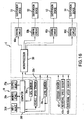
- the electronic controller E will next be explained in relation to navigation device N with reference to Fig. 1 .
- the navigation device N includes a GPS sensor 30a, a vehicle speed sensor 30b and a gyro sensor 30c.
- the GPS sensor 30a detects the present position of the automobile on the basis of respective radio signals from plural geostationary satellites.
- the vehicle speed sensor 30b detects the running speed of the automobile as a vehicle speed.
- the gyro sensor 30c detects an angle of rotation of the automobile around a vertical axis passing through the center of gravity of the automobile.
- the navigation device N has an input device 30d, a memory device 30e, a computer 30f and an output device 30g.
- the input device 30d is used to input necessary information to the computer 30f.
- a series of map data is stored to the memory device 30e as a database so as to be read by the computer 30f.
- the computer 30f executes a navigation control program in accordance with the flow charts shown in Figs. 5 to 7 .
- the computer 30f executes routines required for guidance of the automobile (navigation control program) on the basis of the input from the input device 30d, the data stored in the memory device 30e and each of the outputs of the GPS sensor 30a and the vehicle speed sensor 30b.
- the output device 30g displays data required as information in the automobile, under control of the computer 30f.
- the electronic controller E has respective acceleration sensors 41a to 41d, a steering sensor 42, a microprocessor 50 and respective driving circuits 60a to 60d.
- Each of the acceleration sensors 41 a to 41d is arranged in the vehicle body B adjacent respective suspension devices S1 to S4. Each of these acceleration sensors 41 a to 41 d detects vertical acceleration of the automobile.
- the steering sensor 42 detects a steering angle relative to a neutral position of the steering wheel of the automobile.
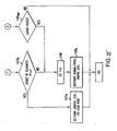
- the microprocessor 50 executes a suspension control program in accordance with the respective flow charts shown in Figs. 8 to 10 to adjust the damping force of each of the suspension devices S1 to S4 on the basis of the output of the computer 30f of the navigation device N, and the outputs of the vehicle speed sensor 30b, the gyro sensor 41e, the respective acceleration sensors 41a to 41d and the steering sensor 42.
- the respective driving circuits 60a to 60d operate the electromagnetic diaphragm valves 13 of the respective suspension devices S1 to S4 under control of the microprocessor 50.
- step 102 map data for the requested map is read from the memory device 30e.
- step 103 a routine for display of the requested map is executed, whereby the output device 30g displays the requested map on the basis of the road map data.
- a route search is executed in step 104 on the basis of the outputs of the GPS sensor 30a and the gyro sensor 41e and an input destination (input using the input device 30d).
- route guidance is provided on the basis of the results of the route search. In accordance with this guidance processing, the automobile driver is assisted in following the route determined by the route search.
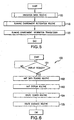
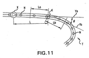
- a travel environment recognition routine 110 (see Figs. 5 and 7 ) is executed as follows. First, as shown in Fig. 11 , it is assumed that plural nodes N show a curve around a corner T. One of these nodes shows a starting point K of the curve as a transition from a road extending in a straight line in the direction of advance of the automobile. The nodes N, included in the road map data, serve as positions for calculating a radius of curvature Ra for the corner T.
- the curve starting point K is judged as follows in step 111 of Fig. 7 .
- the angle formed by straight lines Ya and Yb is calculated as a turning angle 2 at each of the nodes N in advance of the automobile.
- the straight line Ya is a straight line passing through a pair of nodes adjacent to and preceding and following a point a predetermined distance La backward from an object node K.
- the straight line Yb is a straight line passing through nodes adjacent to and preceding and following a position a predetermined distance Lb forward from the object node K.
- the first node for which the calculated turning angle 2 is greater than a predetermined angle is judged to be the curve starting point K.
- the radius of curvature Ra of the corner T is calculated for every node N as the radius of a circle passing through nodes at three points in total, including nodes at two points located before and after a node N at the corner T.
- a minimum value among the radii of curvature calculated in this way is set as radius of curvature Ra of the corner.
- step 112 When step 112 is completed, a running environment information transmission routine is executed (step 120 in Fig. 5 ). In this routine, information relative to the curve starting point K determined in the running environment recognition routine 110 and the radius of curvature Ra of the corner T are output to the electronic controller E.
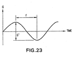
- the filter processing routine 132 involves sampling of the acceleration signal of each of the acceleration sensors 41a to 41 d input in the step 131, and extraction of an acceleration component G' at a predetermined frequency and its averaging, which are performed as follows.
- the acceleration signal G of each of the acceleration sensors 4 1 a to 41d is sequentially sampled with the passage of time, e.g., every tenth acceleration signal from each of the acceleration sensors 41a-41d as shown in Fig. 23 .
- the acceleration component G' corresponding to a predetermined frequency within the range of 10 (Hz) to 20 (Hz) is sequentially extracted from the sampling data for each of the acceleration sensors 41a-41d. All the acceleration components extracted in this way are then averaged to obtain an average acceleration component as the arithmetic mean.
- the above acceleration component determined at a frequency within the range of 10 (Hz) to 20 (Hz) because such a frequency corresponds to irregularity of a road surface which is irregular approximately to the extent of that creating discomfort for a passenger.
- the averaged acceleration component is a component common to the respective suspension devices S1 to S4 of the automobile.
- this first predetermined acceleration corresponds to that from a road surface having a worst case irregularity.
- the first predetermined acceleration is set to, e.g., 2.0 G.
- the degree of irregularity P represents the degree of irregularity of the road surface traveled by the automobile
- step 135 it is then determined in step 135 whether or not the averaged acceleration component is equal to or greater than a second predetermined acceleration.
- this second predetermined acceleration corresponds to a state less irregular than the worst case irregularity corresponding to the first predetermined acceleration, and is set to e.g., 1.0 G in this embodiment.
- step 135 When the averaged acceleration component is equal to or greater than the second predetermined acceleration, the judgement in step 135 is YES.
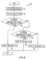
- step 142 the present position X of the automobile is detected on the basis of the output of the GPS sensor 30a from the computer 30f of the navigation device N. The distance L from this detected present position X of the automobile to the curve starting point K is then calculated. It is then judged whether or not this calculated distance L is less than a predetermined distance. When the distance L is not less than this predetermined distance, the judgement is NO in step 142.
- the damping level Cn is a level common for the diaphragm aperture (corresponding to an adjusting amount) of each electromagnetic diaphragm valve 13, i.e., a level corresponding to a common damping force for each of the suspension devices S1 to S4.
- step 144 determination of the damping level Cn common for the diaphragm aperture of each electromagnetic diaphragm valve 13 (corresponding to the damping force of each of the suspension devices S1 to S4) is performed as follows in step 145.
- an estimated transverse acceleration G is calculated on the basis of the vehicle speed V of the automobile and the radius of curvature Ra of the corner T by using the following formula I.
- the estimated transverse acceleration G is an estimated transverse acceleration applied to the automobile in travel of the automobile in a turn around the corner T.
- Vr is a deceleration correction coefficient.
- This deceleration correction coefficient Vr is a correction coefficient for estimating and correcting the deceleration from the vehicle speed V in the present position X of the automobile to the vehicle speed during travel of the automobile around the corner.
- the above formula I is stored in a ROM of the microprocessor 50 in advance.
- the damping level Cn is determined as follows by using the estimated transverse G and the above degree of irregularity P, on the basis of map shape data given in the following Table 1.
- the damping level Cn represents the relationship between the degree of irregularity P and the estimated transverse acceleration G.
- the damping level Cn is increased as the estimated transverse acceleration G increases.
- the estimated transverse acceleration G is increased as the vehicle speed of the automobile during running of the corner is increased or the radius of curvature Ra of the corner is less.
- step 146 when the automobile is found to have started turning the corner in step 146, the judgement is YES, based on the output of the steering sensor 42.
- step 147 it is judged in step 147 whether or not the automobile has passed through the corner T, i.e., completed the turn.
- the judgement is NO in step 147, on the basis of the output of the gyro sensor 41e from the computer 30f.
- the suspension control program proceeds to complete the damping level determination routine 140 without making a new determination of the damping level Cn in step 145.
- each electromagnetic diaphragm valve 13 of the respective suspension devices S1 to S4 is determined as follows in the next step 150 (see Fig. 8 ) in accordance with the result in one of the above steps 143, 145, 147 and 149.
- the diaphragm aperture ⁇ is set so as to be increased (or decreased) in accordance with a reduction (or increase) in the damping level Cn.
- the damping force of each of the suspension devices S1 to S4 is controlled so as to be reduced during straight running of the automobile just before the entry into the turn around the corner T, and riding comfort (ride sensation) during travel along the straight road can be optimized, irrespective of the degree of irregularity of the road surface.
- the diaphragm aperture ⁇ is determined as follows from the ⁇ -Cn characteristics shown in Fig. 15 on the basis of the damping level Cn in step 150.
- Such a determination corresponds to that for a road surface having the worst case degree of irregularity.
- Such a determination corresponds to that for the lowest degree of irregularity of the road surface.
- the respective electromagnetic diaphragm valves 13 greatly reduce the damping forces of the suspension devices S1 to S4.
- each electromagnetic diaphragm valve 13 greatly decreases the amount of flow of the operating oil between the hydraulic compartments 12a and 12b by increasing the resistance to circulation of the operating oil.
- each electromagnetic diaphragm valve 13 greatly increases the damping force of the respective suspension devices S1 to S4.
- step 145 when the damping level Cn is determined in step 145 after a NO determination in step 146, execution of the corner control is started. Thereafter, in straight travel, up to just before entry of the automobile into the turn at corner T, the damping force of each of the suspension devices S1 to S4 is controlled in a manner similar to the case in which the damping force is controlled by adjusting the diaphragm aperture ⁇ in step 150, after the determination YES in step 142.
- step 147 when the judgement is NO in step 147 after a YES determination in step 146, the damping level Cn already determined in step 145, just before the YES determination in step 146 is maintained.
- the damping force of each of the suspension devices S1 to S4 is controlled taking into consideration the degree of irregularity of the road surface just before the entry of the automobile into the curve around corner T and set in advance to be held and utilized as the damping force after entry of the automobile into the curve around corner T. Accordingly, when the automobile enters into the turn (curve) around corner T, the operations of the respective suspension devices S1 to S4 are estimated and controlled so as to maintain the damping force already set in advance just before entry of the automobile into the turn around the corner T. As a result, the steering stability and the ride sensation during travel of the automobile in turning the corner T can be preferably maintained even when there are irregularities in the road surface around the corner T.
- each electromagnetic diaphragm valve 13 greatly increases the flow of the operating oil between the hydraulic compartments 12a and 12b by reducing resistance to circulation of the operating oil.
- the damping force of each of the suspension devices S1 to S4 is reduced to provide a comfortable ride in straight line travel.
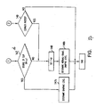
- Fig. 16 shows a second embodiment of the present invention in which rotational speed sensors 43a, 43b are used instead of the acceleration sensors 41a to 41d in the electronic controller E of the above first embodiment.
- Each of these rotational speed sensors 43a, 43b is arranged near a drive wheel of an axle of the automobile.
- Each of these rotational speed sensors 43a, 43b detects the rotational speed of a drive wheel.
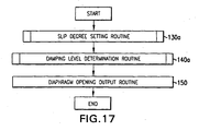
- this second embodiment is operated in accordance with the flow chart of Fig. 17 , instead of the flow chart of Fig. 8 as in the first embodiment. Further, this second embodiment employs the slip degree setting routine 130a of Fig. 18 and the damping level determination routine 140a of Fig. 19 , instead of the degree of irregularity setting routine 130 of Fig. 9 and the damping level determination routine 140 of Fig. 10 in the suspension control program of the first embodiment. Other features are similar to those of the first embodiment.
- the microprocessor 50 of the electronic controller E begins to execute the above suspension control program in accordance with the flow chart of Fig. 17 when execution of the navigation basic routine 100 of Fig. 5 through step 120 has been terminated.
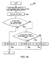
- the suspension control program proceeds to the slip degree setting routine 130a (see Fig. 18 )
- signals from the respective rotational speed sensors 43a, 43b are input to the microprocessor 50 in step 131a.
- the microprocessor 50 calculates an average value (hereinafter referred to as average rotational speed a) of the rotational speeds of the respective drive wheels on the basis of these signals.
- a slip ratio is calculated in a manner which differs depending on whether the automobile is in a driving state or in a braking state.
- driving state means that the automobile is traveling with positive acceleration in its direction of advance.
- braking state means that the automobile is running with negative acceleration with respect to its direction of advance.
- step 133a a judgement is made in step 133a whether or not the slip ratio calculated in the step 132a is equal to or greater than a first predetermined slip ratio.
- this first predetermined slip ratio corresponds to that for a road surface having a worst case slip state.
- the first predetermined slip ratio is set to, e.g., 40%.
- the slip degree SP shows the degree of slip on the road surface as currently traveled by the automobile.
- step 135a a determination is made as to whether or not the slip ratio is equal to or greater than a second predetermined slip ratio.
- This second predetermined slip ratio corresponds to an un-slippery state as compared with the worst case slip state represented by the first predetermined slip ratio.
- the second predetermined slip ratio is set to, e.g., 20%.
- step 144 a determination of a damping level Cn, common to the respective suspension devices S1 to S4, is made in step 145a.
- the estimated transverse acceleration G is calculated by using formula I, on the basis of the vehicle speed V and the radius of curvature Ra of the corner T.
- the damping level Cn is determined as follows, using the estimated transverse acceleration G and the slip degree SP on the basis of map shape data of the following Table 2.
- the damping level Cn is specified by the relationship between the slip degree SP and the estimated transverse acceleration G.
- step 146 on the basis of the output of the steering sensor 42 as in the first embodiment, the determination of a damping level Cn common to the diaphragm apertures of all electromagnetic diaphragm valves 13 is made in step 145a as in the above case.
- step 147 a judgement is made in step 147 whether or not the automobile has completed turning the corner T as described in connection with the first embodiment, just after a judgement YES in step 146. Accordingly, similar to the first embodiment, the judgement is NO in the step 147.
- the suspension control program proceeds to the last step of the damping level determination routine 140a without newly determining the damping level Cn in step 145a.
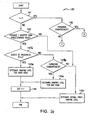
- the diaphragm aperture of each electromagnetic diaphragm valve 13 is set in the next step 150 (see Fig. 17 ), in accordance with the results of one of the steps 143a, 145a, 147, 149a.
- step 145a when the damping level Cn is determined in step 145a after a judgement YES in step 142, the diaphragm aperture ⁇ is determined in step 150 on the basis of the damping level Cn from the ⁇ -Cn characteristic graph of Fig. 15 .
- the electromagnetic diaphragm valves 13 greatly reduce the damping force for each of the suspension devices S1 to S4.
- the electromagnetic diaphragm valves 13 greatly increase the damping force of each of the suspension devices S1 to S4, similar to the above first embodiment.
- the damping force of each of the suspension devices S1 to S4 is reduced just before the automobile enters the turn around the corner T since the road surface has a high degree of slip, but ride comfort in straight running of the automobile can be maintained.
- step 145a when the damping level Cn is determined in step 145a after a judgement NO in step 146, execution of corner control is started. Thereafter, in straight running, until just before the automobile enters into the turn around the corner T, the damping force of each of the suspension devices S1 to S4 is controlled by adjusting the diaphragm aperture ⁇ in step 150 after a determination of YES in step 142.
- step 147 when the judgement is NO in step 147, after a judgement YES in step 146, the damping level Cn already determined in step 145a, just before the judgement YES in step 146 is maintained.
- the damping force of each of the suspension devices S1 to S4 is controlled taking into consideration the slip degree of the road surface just before entry of the automobile into the turn around the corner T and is held and utilized as the damping force after the entry of the automobile into the turn around the corner T, similar to the first embodiment.
- each of the suspension devices S1 to S4 is estimated and controlled so as to maintain the damping force already set, just before the entry of the automobile into the turn around the corner T.
- the stability and the riding comfort in the turning of the automobile around the corner T can be maximized even when the road surface at the corner T is slippery.
- a good-road adjustment is calculated on a basis of a good road surface, the detected vehicle speed and the corner information, and is output to the suspension means.
- a bad-road adjustment is calculated on a basis of the detected degree of roughness, the detected vehicle speed and the corner information determined as the vehicle enters the turn at the corner, and is output to the suspension means.
- the damping force of the suspension means before entering the turn at the corner is controlled in a manner corresponding to a good-road adjustment, thus favorably maintaining steering stability of the vehicle in turning the corner.
- the damping force of the suspension means is controlled in a manner corresponding to the bad-road adjustment when entering the corner, thus, in this case also, favorably maintaining steering stability and riding comfort of the vehicle in turning the corner.
- a bad-road adjustment to the damping force of the suspension means is calculated as above and output to the suspension means. Accordingly, when the vehicle approaches a corner, in the case where the road surface changes from a degree of roughness corresponding to a good road surface to a degree of roughness not corresponding to a good road surface, the damping force of the suspension means is thereafter controlled in accordance with the bad-road adjustment amount so that, in travel around the corner, steering stability and riding comfort are maintained.
- the control system of the present invention may utilize normal travel adjustment calculating means (132, 133 - 137, 142, 143b, 147b, 142a, 148a) for, when the detected degree of roughness no longer corresponds to a good road surface, calculating a normal travel adjustment for damping force of the suspension means on the basis of the detected degree of roughness.
- the normal travel adjustment means may calculate the normal travel adjustment on the basis of either the detected degree of roughness alone or on the basis of the detected degree of roughness in combination with other detected condition or conditions.
- the detected degree of roughness changes from that which has the suspension means controlled in accordance with a bad-road adjustment or with a normal-travel adjustment to that corresponding to a good road surface state
- a good-road adjustment is calculated as above on the basis of the detected degree of roughness, the detected vehicle speed and the corner information, and is output to the suspension means. Accordingly, when the vehicle approaches a corner, in the case that the road surface changes from a degree of roughness not corresponding to a good road surface to a degree of roughness corresponding to a good road surface, the damping force of the suspension means is controlled in a manner corresponding to a good-road adjustment amount.
- the vehicular suspension control system of the present invention includes:
- the damping force of the suspension means is changed from that corresponding to the normal-travel adjustment to that corresponding to a bad-road adjustment.
- the above embodiment may also include the previously described good-road adjustment calculating means.
- one or all of the adjustment calculating means may extract a roughness state component at a predetermined frequency from the signal for degree of roughness output by the roughness state detecting means and calculate the adjustment for damping force of the suspension means on the basis of that roughness state component.
- the vehicular suspension control system of the present invention is installed in a vehicle also equipped with a navigation system and includes:
- a good-road adjustment is calculated on the basis of the detected slip state corresponding to the good road surface, the detected vehicle speed and the corner information, and is output to the suspension means.
- a bad-road adjustment is calculated on a basis of the detected slip, the detected vehicle speed and the corner information, responsive to a determination that the vehicle has entered the turn around the corner, and is output to the suspension means.
- the vehicle As the vehicle approaches the corner, if the slip state of the road surface changes from a slip state corresponding to a good road surface to a slip state not corresponding to a good road surface, the damping force of the suspension means is changed from that for a good road surface to that for a bad road surface when entering the corner. Thus, in travel around the corner, the vehicle maintains favorable stability.
- Those embodiments including a slip state detecting means may have a normal-travel adjustment amount calculating means (132, 133 - 137, 142, 143, 147d, 142b, 148b) for, in the case where the slip state detected by the slip state detecting means does not correspond to a good road surface, calculating a normal-travel adjustment for damping force of the suspension means on the basis of the detected slip state.
- the detected slip state may initially correspond to that of a good road surface, with control in accordance with an adjustment calculated on the basis of the detected slip state, the detected vehicle speed and the corner information.
- a normal-travel adjustment is calculated for the damping force of the suspension means on the basis of the detected slip state, and is output to the suspension means.
- a good-road adjustment is calculated for the damping force on the basis of the detected slip state, the detected vehicle speed and the corner information, and is output to the suspension means.
- the vehicular suspension control system of the present invention is installed in a vehicle also equipped with a navigation system and includes:
- the damping force of the suspension means is changed to that corresponding to a bad-road adjustment from the normal-travel adjustment.
- each of the adjustment calculating means may determine a degree of slip at a predetermined frequency from the slip state detected by the slip state detecting means and calculate the adjustment amount for damping on the basis of the determined degree of slip.
- the present invention provides a method for control of suspension means in a vehicle equipped with a navigation system, which method includes:
- the suspension means is controlled in accordance with the good-road adjustment or the bad-road adjustment, both of which are calculated on the basis of the detected degree of roughness, the detected vehicle speed and the corner information.
- the damping force of the suspension means is controlled in a manner corresponding to bad-road adjustment when entering the turn around the corner.
- the damping force of the suspension means is changed from control in accordance with the good-road adjustment to control in accordance with the normal-travel adjustment.
- control method combines the calculating and utilization of the normal-travel adjustment with calculating and utilization of the bad-road adjustment, optionally also with calculating and utilization of the good-road adjustment.
- control of the damping force of the suspension means is changed from that in accordance with the good-road adjustment to that in accordance with the bad-road adjustment.
- the calculation of a normal-travel adjustment for a detected slip state which does not correspond to a good road surface, based on the detected slip state may be included in the foregoing embodiment of the method or may be substituted for either the good-road adjustment calculation or the bad-road adjustment amount calculation.
- step 142 a current position X of the automobile is obtained from the computer 30f of the navigation system N, based on output of the GPS sensor 30a. The distance L from the detected current position X of the automobile to the curve starting point K is calculated and a determination is made as to whether or not the calculated distance L is less than a predetermined distance. If the calculated distance L is not less than the predetermined distance, the determination in step 142 is NO.
- the damping level Cn is a level common for the aperture openings of the electromagnetic reduction valves 13 and which corresponds to the damping force of the suspension unit S 1 - S4.
- estimated lateral G is calculated on the basis of the vehicle speed V and the radius of curvature Ra of a corner T, by use of the following Equation I.
- estimated lateral G is a horizontal estimated acceleration that the automobile will undergo upon turning the corner T.
- the Equation I is stored in the ROM of the microprocessor 50.
- the data of Table 1 is prestored in the ROM of the microprocessor 50, together with the data map of table 2 referred to later.
- the damping level Cn increases with increase in estimated lateral G, as shown in Fig. 12 . Further, as the speed V of the automobile turning the corner becomes higher and as the radius of curvature Ra of the corner T becomes smaller, the estimated lateral G becomes greater.
- step 145b when the automobile has commenced cornering, the determination is YES, on the basis of the signal output by the steering sensor 42. Then, in step 145a, a process of determining a damping level Cn common to the suspension units S1 - S4, is executed as follows.
- an estimated lateral G is calculated on the basis of vehicle speed V of the automobile and radius of curvature Ra of the corner T, by use of the foregoing Equation I.
- Damping level Cn is determined by use of an estimated lateral G and the degree of roughness P, as follows, on the basis of the data map shown in Table 4 below.
- damping level Cn is specified in relation to degree of roughness P and estimated lateral G.
- damping level Cn is specified to increase with increase in the estimated lateral G, as shown in Figs. 3 and 14 .
- step 147b a damping level Cn common to the suspension units S1 - S4 is determined by applying an estimated lateral G to the data map of Table 3, similar to step 143a.
- step 146 if the automobile has commenced cornering, the determination is YES on the basis of the output of the steering sensor 42. Then, in step 149a of Fig. 25 , it is determined whether or not the automobile has passed the corner T. Immediately after the determination YES in step 146, a determination NO is made in step 149a on the basis of output of gyro sensor 30b from the computer 30f.
- the suspension control program proceeds to the end of the damping-level determination routine 140 without determining a new damping level Cn.
- the damping level Cn is then held until a determination of YES in step 149a.
- step 150 the electromagnetic reduction valves 13 of the suspension units S1 - S4 have their apertures adjusted in accordance with the damping level determined in step 142a (or 148a), 143a (or 147a) or 145a or by NO in step 149a.
- the diaphragm aperture opening ⁇ increases with a decrease of damping level Cn, as shown in Fig. 15 .
- each electromagnetic reduction valve 13 greatly increases the amount of flow of operating oil between the hydraulic chambers 12a, 12b, thereby greatly reducing the resistance to flow of operating oil. In this manner, when the automobile is traveling straight at a point further from the corner T than the predetermined value, the damping force of the suspension unit S 1 - S4 is made smaller with emphasis on driving comfort, in a manner suited for the normal travel of the automobile.
- the aperture opening ⁇ thus determined is output as data in step 150 to the drive circuits 60a - 60d. Based on the output, the damping force of each suspension unit S 1 - S4 is controlled as follows.
- the damping level Cn is determined in step 147a on the basis of a procedure similar to that of step 143a. Accordingly, even in further straight travel of the automobile after the distance L to the corner T has become less than the predetermined distance, the damping force of each suspension unit S1 - S4 can be changed to place more emphasis on steering stability immediately before entering the turn around the corner. Moreover, because the road surface is at the most moderate degree of roughness, the automobile is comfortable to drive during straight travel after the distance L to the corner T has become less than the predetermined distance.
- the aperture opening ⁇ thus determined is output as data in step 150 to the drive circuits 60a - 60d. Based on the output data, the damping force of each suspension unit S1 - S4 is controlled as follows.
- step 149a When the automobile commences cornering, there is a determination of YES in step 146 on the basis of output of gyro sensor 30b from the computer 30f.
- the determination routine of step 149a is then initiated and, when the determination in step 149a is NO, the damping level Cn which has already been determined in step 143a (or 147a) or 145a is maintained.
- the most currently determined damping level Cn i.e. the damping level Cn immediately before entering the turn at the corner T, is maintained as determined in step 143a or 145a in a previously executed cycle.
- a suitable damping force for each suspension unit S1 - S4 is predicted and set in advance, taking into consideration the degree of roughness of the road surface as detected immediately before or immediately after entering the turn at the corner T of the automobile, in order to hold and utilize that damping force during cornering at the corner T by the automobile.
- the suspension units S1 - S4 are controlled with a damping force previously set immediately before or immediately after entering the turn at corner T.
- a damping force previously set immediately before or immediately after entering the turn at corner T.
- step 142 it is determined whether or not the distance L, calculated in a manner similar to step 142 (see Fig. 24 ) is less than the predetermined distance.
- step 142 becomes YES when the distance L becomes less than the predetermined distance.
- step 143d determination of a damping level Cn common to the suspension units S 1 - S4 is executed as follows.
- an estimated lateral G is calculated based on the speed V of the automobile and the radius of curvature Ra of the corner T, by use of the foregoing Equation 1.
- the damping level Cn is determined as follows based on a data map as represented by Table 5 below, by use of the estimated lateral G.
- the data map of Table 5 may be prestored in the ROM of the microprocessor 50, together with the data map of Table 6 below.
- damping level Cn increases with increasing estimated lateral G as shown in Fig. 20 .
- step 145 if the automobile has commenced cornering, the determination is YES based on the output of the steering sensor 42. Then, in step 145c, a determination of a damping level Cn common to the suspension units S 1 - S4 is executed as follows.
- an estimated lateral G is calculated based on the speed V of the automobile and the radius of curvature Ra of the corner T, by use of the foregoing Equation I.
- Damping level Cn is determined based on the data map shown in Table 6 below, by use of the estimated lateral G and the foregoing degree of slip SP, as follows.
- damping level Cn is specified in relationship with degree of slip SP and estimated lateral G.
- damping level Cn increases with increasing estimated lateral G in the relationship between a damping level Cn and an estimated lateral G, as shown in Figs. 21 and 27 .
- step 147d a damping level Cn common to the suspension units S1 - S4 is determined by using an estimated lateral G on the basis of the data map of Table 5, similar to step 143c.
- step 146 if the automobile has commenced cornering, the determination is YES based on output of the steering sensor 42. Then, in step 149 of Fig. 27 , it is determined whether or not the automobile has passed the corner T, similar to the first embodiment. Immediately after a determination of YES in step 146, the determination NO is made in step 149, similar to the first embodiment, on the basis of output of gyro sensor 30b from the computer 30f.
- the suspension control program proceeds to the end step of the damping-level determination routine 140a without newly determining a damping level Cn.
- step 149 the determination becomes YES in step 149, similar to the first embodiment.
- an aperture setting process is executed in the next step 150 (see Fig. 17 ).
- the degree of opening of the aperture of the electromagnetic reduction valve 13 of each suspension unit S1 - S4 is determined by the process of damping level determination in the foregoing step 142b (or 148b), 143c (or 147c) or 145c or in step 149 with a determination of NO, as follows.
- each suspension unit S 1 - S4 is decreased so as to emphasize behavior stability suited for normal travel, when the automobile is traveling straight at a point further from the corner T than the predetermined value.
- the degree of opening ⁇ thus determined is output as data in step 150 to the drive circuits 60a - 60d. Based on this output data, the damping force of each suspension unit S1 - S4 is controlled as follows.
- electromagnetic reduction valves 13 greatly increase the damping forces of the suspension unit S1 - S4, similar to the first embodiment.
- damping level Cn is determined in step 147c in a manner similar to the determination in step 143c. Accordingly, even in straight travel of the automobile after the distance L to the corner T has become less than the predetermined distance, control of the damping force of each suspension unit S1 - S4 can be changed to place emphasis on steering stability in cornering immediately before entering the turn around the corner. Moreover, because the road surface is in the least slidable state, the automobile has good stability during straight travel of the automobile after the distance L to the corner T becomes less than the predetermined distance.
- Such a determination corresponds to a road surface of the worst slip degree.
- the aperture opening ⁇ thus determined is output as data in step 150 to the drive circuits 60a - 60d. Based on this output data, the damping force of each suspension unit S1 - S4 is controlled as below.
- step 149 after a YES determination in step 146, following execution of steps 143d, 143c and 144, the most currently determined damping level Cn, i.e. the damping level Cn immediately before entering the turn at the corner T, is maintained in step 143c.
- step 149 In the case of a NO determination in step 149 after a YES determination in step 146, following execution of steps 143d, 145, 145c and 144, the most recently determined damping level Cn, i.e. the damping level Cn immediately after entering the turn at corner T, is maintained in step 145c.
- each suspension unit S1 - S4 is predicted and controlled in advance, taking into consideration the degree of slip of the road surface immediately before or immediately after entering the turn at the corner T, which damping force is held and utilized throughout cornering at the corner T.
- the suspension units S1 - S4 are controlled with a damping force previously set immediately before or immediately after entering the turn at the corner T. As a result, even if there is a slip in the road surface at the corner T, it is possible to maintain stability in turning the corner T.
Landscapes
- Engineering & Computer Science (AREA)
- Mechanical Engineering (AREA)
- Automation & Control Theory (AREA)
- Vehicle Body Suspensions (AREA)
Claims (10)
- Aufhängungssteuersystem für ein mit einer Navigationsvorrichtung ausgestattetes Fahrzeug, wobei das Aufhängungssteuersystem enthält:eine Mehrzahl an Aufhängungsvorrichtungen (S1-S4), die jeweils zwischen einem Aufhängungsarm und einem Aufbaubereich des Fahrzeugs befestigt sind, in Verbindung mit einem Rad des Fahrzeugs, wobei sich jede der Aufhängungsvorrichtungen entsprechend einer Dämpfungskraft entspannt und kontrahiert, um Kräfte auf das Fahrzeug zu dämpfen, die von einer Oberfläche einer Straße her empfangen werden, auf der das Fahrzeug fährt;Erfassungsmittel (41a-41d; 43a, 43b) zum Erfassen eines Straßenoberflächenzustandes;Fahrzeuggeschwindigkeitserfassungsmittel (30b) zum Erfassen einer Fahrzeuggeschwindigkeit;Berechnungsmittel (50) zum Berechnen eines Einstellwerts, der der Dämpfungskraft entspricht, auf der Basis der ermittelten Fahrzeuggeschwindigkeit, des ermittelten Straßenoberflächenzustandes und von Informationen betreffend eine Kurve in der Straßenoberfläche, die von der Navigationsvorrichtung erhalten werden, wenn sich das Fahrzeug der Kurve nähert; undAusgabemittel (60a-60d) zum Ausgeben des Einstellwerts an eine Aufhängungsvorrichtung, um die Dämpfungskraft der Aufhängungsvorrichtung zu steuern.
- Aufhängungssteuersystem für ein Fahrzeug, nach Anspruch 1, wobei das Aufhängungssteuersystem weiter enthält:Drehungserfassungsmittel (30c) zum Erfassen einer Drehung des Fahrzeugs; undEintrittsbeurteilungsmittel (N) zum Beurteilen ob das Fahrzeug in eine Kurve eingefahren ist, auf der Basis der Drehung des Fahrzeugs, die durch das Drehungserfassungsmittel ermittelt wurde; undwobei das Ausgabemittel (60a-60d) den Einstellwert an die Aufhängungsvorrichtungen (S1-S4) ausgibt, um die Dämpfungskräfte entsprechend dem Einstellwert zu steuern, in Reaktion auf eine Beurteilung durch das Eintrittsbeurteilungsmittel, dass das Fahrzeug in eine Kurve eingefahren ist.
- Aufhängungssteuersystem für ein Fahrzeug, nach Anspruch 2, wobei das Berechnungsmittel (50) die Berechnung des Einstellwerts in Übereinstimmung mit einer Bewertung durch das Eintrittsbeurteilungsmittel (N), dass das Fahrzeug in eine Drehung um diese Kurve eingetreten ist, stoppt, und wobei der Einstellwert, der zuletzt vor Beendung der Berechnung berechnet wurde, dazu verwendet wird, die Dämpfungskraft der Aufhängungsvorrichtungen bei der Kurvenfahrt des Fahrzeugs zu steuern.
- Aufhängungssteuersystem für ein Fahrzeug, nach Anspruch 3, wobei der Einstellwert, der zuletzt vor dem Beenden der Berechnung berechnet wurde, beibehalten wird, bis das Fahrzeug die Kurve passiert hat.
- Aufhängungssteuersystem für ein Fahrzeug, nach einem der Ansprüche 1 bis 4, wobei das Erfassungsmittel (41 a-41 c) einen Grad der Unregelmäßigkeit der Straßenoberfläche ermittelt.
- Aufhängungssteuersystem für ein Fahrzeug, nach Anspruch 5, wobei das Berechnungsmittel (50) eine Unregelmäßigkeitskomponente, die einer vorbestimmten Frequenz entspricht, aus dem Grad an Unregelmäßigkeit, die durch das Erfassungsmittel ermittelt wird, herleitet und den Einstellwert entsprechend der Dämpfungskraft der Aufhängungseinrichtung auf der Basis der Unregelmäßigkeitskomponente berechnet.
- Aufhängungssteuersystem für ein Fahrzeug, das mit einer Navigationsvorrichtung ausgestattet ist, nach einem der Ansprüche 1 bis 4, wobei das Erfassungsmittel (43a, 43b) einen Rutschzustand der Straßenoberfläche ermittelt.
- Aufhängungssteuerungsverfahren für die Kurvenfahrt eines Fahrzeugs, das mit einer Navigationsvorrichtung und mit Radaufhängungsvorrichtungen ausgestattet ist, wobei das Aufhängungssteuerungsverfahren enthält:Ermitteln der gegenwärtigen Fahrzeugposition;Ermitteln der Annäherung des Fahrzeugs an eine Kurve;Ermitteln eines Straßenoberflächenzustandes an der ermittelten gegenwärtigen Position;Erhalten von Kurveninformationen von der Navigationsvorrichtung;Berechnen eines Einstellwerts, der der Dämpfungskraft der Aufhängungsvorrichtungen entspricht, auf der Basis sowohl des ermittelten Straßenoberflächenzustandes als auch der Kurveninformationen, die von der Navigationsvorrichtung erhalten wurde; undSteuern der Dämpfungskraft der Aufhängungsvorrichtungen in Übereinstimmung mit dem berechneten Einstellwert.
- Aufhängungssteuerungsverfahren für die Kurvenfahrt eines Fahrzeugs, das mit einer Navigationsvorrichtung und mit Radaufhängungsvorrichtungen ausgestattet ist, nach Anspruch 8, wobei:ein Grad der Unregelmäßigkeit der Straßenoberfläche als ein Straßenoberflächenzustand ermittelt wird; undder Einstellwert, der der Dämpfungskraft der Aufhängungsvorrichtung entspricht, auf der Basis der ermittelten Fahrzeuggeschwindigkeit, des ermittelten Rutschzustands der Straßenoberfläche und der Kurveninformationen, die von der Navigationsvorrichtung erhalten werden, berechnet wird.
- Aufhängungssteuerungsverfahren für die Kurvenfahrt eines Fahrzeugs, das mit einer Navigationsvorrichtung und mit Radaufhängungsvorrichtungen versehen ist, nach Anspruch 8, wobei:ein Rutschzustand der Straßenoberfläche als ein Straßenoberflächenzustand ermittelt wird; undder Einstellwert, der einer Dämpfungskraft der Aufhängungsvorrichtungen entspricht, auf der Basis der ermittelten Fahrzeuggeschwindigkeit, des ermittelten Rutschzustands der Straßenoberfläche, und der Kurveninformationen, die von der Navigationsvorrichtung erhalten werden, berechnet wird.
Priority Applications (1)
| Application Number | Priority Date | Filing Date | Title |
|---|---|---|---|
| EP04024056A EP1541389A3 (de) | 2003-09-26 | 2004-09-27 | System und Verfahren zur Regelung einer Fahrzeugaufhängung |
Applications Claiming Priority (4)
| Application Number | Priority Date | Filing Date | Title |
|---|---|---|---|
| JP2003336127 | 2003-09-26 | ||
| JP2003336127A JP3988704B2 (ja) | 2003-09-26 | 2003-09-26 | 車両のサスペンション制御システム及び制御方法 |
| JP2003346000 | 2003-10-03 | ||
| JP2003346000A JP2005112041A (ja) | 2003-10-03 | 2003-10-03 | 車両用サスペンション制御システム及びサスペンション制御方法 |
Related Child Applications (1)
| Application Number | Title | Priority Date | Filing Date |
|---|---|---|---|
| EP04024056A Division EP1541389A3 (de) | 2003-09-26 | 2004-09-27 | System und Verfahren zur Regelung einer Fahrzeugaufhängung |
Publications (3)
| Publication Number | Publication Date |
|---|---|
| EP1518722A2 EP1518722A2 (de) | 2005-03-30 |
| EP1518722A3 EP1518722A3 (de) | 2006-09-27 |
| EP1518722B1 true EP1518722B1 (de) | 2009-05-13 |
Family
ID=34197268
Family Applications (2)
| Application Number | Title | Priority Date | Filing Date |
|---|---|---|---|
| EP04022941A Expired - Lifetime EP1518722B1 (de) | 2003-09-26 | 2004-09-27 | System und Verfahren zur Regelung einer Fahrzeugaufhängung |
| EP04024056A Withdrawn EP1541389A3 (de) | 2003-09-26 | 2004-09-27 | System und Verfahren zur Regelung einer Fahrzeugaufhängung |
Family Applications After (1)
| Application Number | Title | Priority Date | Filing Date |
|---|---|---|---|
| EP04024056A Withdrawn EP1541389A3 (de) | 2003-09-26 | 2004-09-27 | System und Verfahren zur Regelung einer Fahrzeugaufhängung |
Country Status (3)
| Country | Link |
|---|---|
| EP (2) | EP1518722B1 (de) |
| AT (1) | ATE431264T1 (de) |
| DE (1) | DE602004021073D1 (de) |
Families Citing this family (9)
| Publication number | Priority date | Publication date | Assignee | Title |
|---|---|---|---|---|
| DE102006014992A1 (de) * | 2006-03-31 | 2007-10-04 | Dr.Ing.H.C. F. Porsche Ag | Verfahren und Vorrichtung zur betriebssituationsabhängigen Einstellung der Schwingungseigenschaften von Lagerelementen zur Lagerung eines Aggregats, insbesondere einer Brennkraftmaschine und/oder eines Getriebes, in einem Kraftfahrzeug |
| JP5041946B2 (ja) * | 2007-09-26 | 2012-10-03 | アイシン・エィ・ダブリュ株式会社 | スタビライザ制御装置、スタビライザ制御方法およびスタビライザ制御プログラム |
| DE102008052134B4 (de) * | 2007-10-22 | 2020-08-06 | Continental Teves Ag & Co. Ohg | Verfahren und Vorrichtung zum Verbessern des Fahrverhaltens eines Kraftfahrzeugs |
| DE102007051209A1 (de) * | 2007-10-26 | 2009-04-30 | Volkswagen Ag | Verfahren oder Regelungssystemkomponente zur Steuerung von Aktoren vorzugsweise der Dämpfer eines Fahrzeugs über Querdynamikzustandsgrößen |
| FR2924053B1 (fr) * | 2007-11-23 | 2009-12-25 | Renault Sas | Procede de commande de l'activation/desactivation d'un systeme antiroulis pour vehicule automobile et dispositif correspondant |
| US9522586B2 (en) * | 2015-02-10 | 2016-12-20 | Ford Global Technologies, Llc | Enhanced road characterization for adaptive mode drive |
| KR102382092B1 (ko) * | 2016-07-11 | 2022-04-04 | 현대자동차주식회사 | 요철로 주행시 자동차의 운전성 향상을 위한 시스템 및 그 제어 방법 |
| JP6285591B1 (ja) * | 2017-03-24 | 2018-02-28 | 株式会社ショーワ | サスペンション制御装置、および、サスペンション装置 |
| CN116533700B (zh) * | 2023-06-05 | 2026-04-17 | 北京理工大学 | 一种面向自动驾驶车辆的可控悬架控制系统及方法 |
Family Cites Families (8)
| Publication number | Priority date | Publication date | Assignee | Title |
|---|---|---|---|---|
| JP2834808B2 (ja) * | 1989-12-08 | 1998-12-14 | 三菱電機株式会社 | 自動車用制御装置 |
| JP3133770B2 (ja) * | 1991-01-18 | 2001-02-13 | マツダ株式会社 | 自動車の走行システム |
| JPH09114367A (ja) * | 1995-10-24 | 1997-05-02 | Mitsubishi Electric Corp | 車載走行制御装置 |
| DE19600734C2 (de) * | 1996-01-11 | 2003-03-06 | Zahnradfabrik Friedrichshafen | Verfahren zur Steuerung von Aggregaten und/oder Systemen eines Kraftfahrzeugs |
| DE19745166A1 (de) * | 1997-10-13 | 1999-04-15 | Volkswagen Ag | Verfahren zur Sicherheitsüberwachung eines Kraftfahrzeuges |
| DE10060536A1 (de) * | 2000-12-06 | 2002-06-13 | Bayerische Motoren Werke Ag | Verfahren zur Steuerung des Fahrwerksystems eines zweispurigen Kraftfahrzeuges sowie entsprechendes Kraftfahrzeug |
| DE10164481A1 (de) * | 2000-12-30 | 2002-07-04 | Bosch Gmbh Robert | System zur Betätigung eines gekuppelten Querstabilisators bei einem Kraftfahrzeug |
| JP2003050605A (ja) * | 2001-08-07 | 2003-02-21 | Mazda Motor Corp | 自動車の制御ゲイン変更用サーバ、自動車の制御ゲイン変更方法、及び、自動車の制御ゲイン変更用プログラム |
-
2004
- 2004-09-27 EP EP04022941A patent/EP1518722B1/de not_active Expired - Lifetime
- 2004-09-27 EP EP04024056A patent/EP1541389A3/de not_active Withdrawn
- 2004-09-27 AT AT04022941T patent/ATE431264T1/de not_active IP Right Cessation
- 2004-09-27 DE DE602004021073T patent/DE602004021073D1/de not_active Expired - Lifetime
Also Published As
| Publication number | Publication date |
|---|---|
| DE602004021073D1 (de) | 2009-06-25 |
| EP1518722A2 (de) | 2005-03-30 |
| EP1541389A2 (de) | 2005-06-15 |
| ATE431264T1 (de) | 2009-05-15 |
| EP1541389A3 (de) | 2006-09-27 |
| EP1518722A3 (de) | 2006-09-27 |
Similar Documents
| Publication | Publication Date | Title |
|---|---|---|
| US7680573B2 (en) | Suspension control system and suspension control method for vehicle | |
| US20050090956A1 (en) | Vehicle suspension control system and suspension control method | |
| CN112477750B (zh) | 大灯照射角度调节方法、装置、系统、设备及存储介质 | |
| CN112721910B (zh) | 一种汽车主动抗侧倾稳定控制系统及其方法 | |
| KR101698599B1 (ko) | 서스펜션 제어 장치 | |
| EP0235695B1 (de) | System für das Ausregeln der Rollbewegung des Fahrzeugaufbaus, wobei die schnelle Änderung des Lenkwinkels, wie bei Notmanövern, detektiert und kompensiert wird | |
| US12528453B2 (en) | Vehicle control apparatus, vehicle control method, and vehicle control system | |
| CN116209587A (zh) | 车辆主动悬架控制系统和方法 | |
| JPS63251318A (ja) | 自動車の走行状況適応サスペンシヨン制御方式 | |
| JP3070626B2 (ja) | 車両懸架装置 | |
| US8209067B2 (en) | Height control device for vehicle | |
| EP1518722B1 (de) | System und Verfahren zur Regelung einer Fahrzeugaufhängung | |
| US5962980A (en) | Method for regulating the range of the headlights of a vehicle according to the load | |
| JP3072672B2 (ja) | 車両運動制御装置 | |
| CN108216257B (zh) | 对具有后轮转向系统的车辆进行侧滑角可变控制的方法 | |
| JPH06115335A (ja) | 車輌の車体姿勢制御装置 | |
| JPH07186668A (ja) | サスペンションの制御装置 | |
| US20040212159A1 (en) | Method for adjusting a damping coefficient of a spring strut of a vehicle and arrangement therefor | |
| CN111824254B (zh) | 车辆的转向控制方法和系统 | |
| US20240246383A1 (en) | Method and control device for level control of a motor vehicle | |
| JP4241233B2 (ja) | 車両用サスペンション制御システム | |
| JP3272828B2 (ja) | 車両用サスペンション装置 | |
| KR100229413B1 (ko) | 자동차의 롤링 제어장치 및 그 제어방법 | |
| JPH0648147A (ja) | 車両懸架装置 | |
| JP2021039001A (ja) | 車両積載重量検出方法および車両積載重量検出装置 |
Legal Events
| Date | Code | Title | Description |
|---|---|---|---|
| PUAI | Public reference made under article 153(3) epc to a published international application that has entered the european phase |
Free format text: ORIGINAL CODE: 0009012 |
|
| AK | Designated contracting states |
Kind code of ref document: A2 Designated state(s): AT BE BG CH CY CZ DE DK EE ES FI FR GB GR HU IE IT LI LU MC NL PL PT RO SE SI SK TR |
|
| AX | Request for extension of the european patent |
Extension state: AL HR LT LV MK |
|
| PUAL | Search report despatched |
Free format text: ORIGINAL CODE: 0009013 |
|
| AK | Designated contracting states |
Kind code of ref document: A3 Designated state(s): AT BE BG CH CY CZ DE DK EE ES FI FR GB GR HU IE IT LI LU MC NL PL PT RO SE SI SK TR |
|
| AX | Request for extension of the european patent |
Extension state: AL HR LT LV MK |
|
| 17P | Request for examination filed |
Effective date: 20070320 |
|
| AKX | Designation fees paid |
Designated state(s): AT BE BG CH CY CZ DE DK EE ES FI FR GB GR HU IE IT LI LU MC NL PL PT RO SE SI SK TR |
|
| 17Q | First examination report despatched |
Effective date: 20070510 |
|
| GRAP | Despatch of communication of intention to grant a patent |
Free format text: ORIGINAL CODE: EPIDOSNIGR1 |
|
| GRAS | Grant fee paid |
Free format text: ORIGINAL CODE: EPIDOSNIGR3 |
|
| GRAA | (expected) grant |
Free format text: ORIGINAL CODE: 0009210 |
|
| AK | Designated contracting states |
Kind code of ref document: B1 Designated state(s): AT BE BG CH CY CZ DE DK EE ES FI FR GB GR HU IE IT LI LU MC NL PL PT RO SE SI SK TR |
|
| REG | Reference to a national code |
Ref country code: GB Ref legal event code: FG4D |
|
| REG | Reference to a national code |
Ref country code: CH Ref legal event code: EP |
|
| REG | Reference to a national code |
Ref country code: IE Ref legal event code: FG4D |
|
| REF | Corresponds to: |
Ref document number: 602004021073 Country of ref document: DE Date of ref document: 20090625 Kind code of ref document: P |
|
| PG25 | Lapsed in a contracting state [announced via postgrant information from national office to epo] |
Ref country code: FI Free format text: LAPSE BECAUSE OF FAILURE TO SUBMIT A TRANSLATION OF THE DESCRIPTION OR TO PAY THE FEE WITHIN THE PRESCRIBED TIME-LIMIT Effective date: 20090513 Ref country code: AT Free format text: LAPSE BECAUSE OF FAILURE TO SUBMIT A TRANSLATION OF THE DESCRIPTION OR TO PAY THE FEE WITHIN THE PRESCRIBED TIME-LIMIT Effective date: 20090513 Ref country code: ES Free format text: LAPSE BECAUSE OF FAILURE TO SUBMIT A TRANSLATION OF THE DESCRIPTION OR TO PAY THE FEE WITHIN THE PRESCRIBED TIME-LIMIT Effective date: 20090824 Ref country code: PT Free format text: LAPSE BECAUSE OF FAILURE TO SUBMIT A TRANSLATION OF THE DESCRIPTION OR TO PAY THE FEE WITHIN THE PRESCRIBED TIME-LIMIT Effective date: 20090913 |
|
| NLV1 | Nl: lapsed or annulled due to failure to fulfill the requirements of art. 29p and 29m of the patents act | ||
| PG25 | Lapsed in a contracting state [announced via postgrant information from national office to epo] |
Ref country code: PL Free format text: LAPSE BECAUSE OF FAILURE TO SUBMIT A TRANSLATION OF THE DESCRIPTION OR TO PAY THE FEE WITHIN THE PRESCRIBED TIME-LIMIT Effective date: 20090513 Ref country code: SE Free format text: LAPSE BECAUSE OF FAILURE TO SUBMIT A TRANSLATION OF THE DESCRIPTION OR TO PAY THE FEE WITHIN THE PRESCRIBED TIME-LIMIT Effective date: 20090813 Ref country code: SI Free format text: LAPSE BECAUSE OF FAILURE TO SUBMIT A TRANSLATION OF THE DESCRIPTION OR TO PAY THE FEE WITHIN THE PRESCRIBED TIME-LIMIT Effective date: 20090513 Ref country code: NL Free format text: LAPSE BECAUSE OF FAILURE TO SUBMIT A TRANSLATION OF THE DESCRIPTION OR TO PAY THE FEE WITHIN THE PRESCRIBED TIME-LIMIT Effective date: 20090513 |
|
| PG25 | Lapsed in a contracting state [announced via postgrant information from national office to epo] |
Ref country code: CZ Free format text: LAPSE BECAUSE OF FAILURE TO SUBMIT A TRANSLATION OF THE DESCRIPTION OR TO PAY THE FEE WITHIN THE PRESCRIBED TIME-LIMIT Effective date: 20090513 Ref country code: EE Free format text: LAPSE BECAUSE OF FAILURE TO SUBMIT A TRANSLATION OF THE DESCRIPTION OR TO PAY THE FEE WITHIN THE PRESCRIBED TIME-LIMIT Effective date: 20090513 Ref country code: RO Free format text: LAPSE BECAUSE OF FAILURE TO SUBMIT A TRANSLATION OF THE DESCRIPTION OR TO PAY THE FEE WITHIN THE PRESCRIBED TIME-LIMIT Effective date: 20090513 Ref country code: DK Free format text: LAPSE BECAUSE OF FAILURE TO SUBMIT A TRANSLATION OF THE DESCRIPTION OR TO PAY THE FEE WITHIN THE PRESCRIBED TIME-LIMIT Effective date: 20090513 |
|
| PG25 | Lapsed in a contracting state [announced via postgrant information from national office to epo] |
Ref country code: BE Free format text: LAPSE BECAUSE OF FAILURE TO SUBMIT A TRANSLATION OF THE DESCRIPTION OR TO PAY THE FEE WITHIN THE PRESCRIBED TIME-LIMIT Effective date: 20090513 Ref country code: SK Free format text: LAPSE BECAUSE OF FAILURE TO SUBMIT A TRANSLATION OF THE DESCRIPTION OR TO PAY THE FEE WITHIN THE PRESCRIBED TIME-LIMIT Effective date: 20090513 |
|
| PLBE | No opposition filed within time limit |
Free format text: ORIGINAL CODE: 0009261 |
|
| STAA | Information on the status of an ep patent application or granted ep patent |
Free format text: STATUS: NO OPPOSITION FILED WITHIN TIME LIMIT |
|
| PG25 | Lapsed in a contracting state [announced via postgrant information from national office to epo] |
Ref country code: BG Free format text: LAPSE BECAUSE OF FAILURE TO SUBMIT A TRANSLATION OF THE DESCRIPTION OR TO PAY THE FEE WITHIN THE PRESCRIBED TIME-LIMIT Effective date: 20090813 |
|
| 26N | No opposition filed |
Effective date: 20100216 |
|
| PG25 | Lapsed in a contracting state [announced via postgrant information from national office to epo] |
Ref country code: MC Free format text: LAPSE BECAUSE OF NON-PAYMENT OF DUE FEES Effective date: 20090930 |
|
| REG | Reference to a national code |
Ref country code: CH Ref legal event code: PL |
|
| GBPC | Gb: european patent ceased through non-payment of renewal fee |
Effective date: 20090927 |
|
| REG | Reference to a national code |
Ref country code: IE Ref legal event code: MM4A |
|
| REG | Reference to a national code |
Ref country code: FR Ref legal event code: ST Effective date: 20100531 |
|
| PG25 | Lapsed in a contracting state [announced via postgrant information from national office to epo] |
Ref country code: IE Free format text: LAPSE BECAUSE OF NON-PAYMENT OF DUE FEES Effective date: 20090927 Ref country code: FR Free format text: LAPSE BECAUSE OF NON-PAYMENT OF DUE FEES Effective date: 20090930 |
|
| PG25 | Lapsed in a contracting state [announced via postgrant information from national office to epo] |
Ref country code: CH Free format text: LAPSE BECAUSE OF NON-PAYMENT OF DUE FEES Effective date: 20090930 Ref country code: LI Free format text: LAPSE BECAUSE OF NON-PAYMENT OF DUE FEES Effective date: 20090930 Ref country code: GR Free format text: LAPSE BECAUSE OF FAILURE TO SUBMIT A TRANSLATION OF THE DESCRIPTION OR TO PAY THE FEE WITHIN THE PRESCRIBED TIME-LIMIT Effective date: 20090814 |
|
| PG25 | Lapsed in a contracting state [announced via postgrant information from national office to epo] |
Ref country code: GB Free format text: LAPSE BECAUSE OF NON-PAYMENT OF DUE FEES Effective date: 20090927 |
|
| PG25 | Lapsed in a contracting state [announced via postgrant information from national office to epo] |
Ref country code: IT Free format text: LAPSE BECAUSE OF FAILURE TO SUBMIT A TRANSLATION OF THE DESCRIPTION OR TO PAY THE FEE WITHIN THE PRESCRIBED TIME-LIMIT Effective date: 20090513 |
|
| PG25 | Lapsed in a contracting state [announced via postgrant information from national office to epo] |
Ref country code: LU Free format text: LAPSE BECAUSE OF NON-PAYMENT OF DUE FEES Effective date: 20090927 |
|
| PG25 | Lapsed in a contracting state [announced via postgrant information from national office to epo] |
Ref country code: HU Free format text: LAPSE BECAUSE OF FAILURE TO SUBMIT A TRANSLATION OF THE DESCRIPTION OR TO PAY THE FEE WITHIN THE PRESCRIBED TIME-LIMIT Effective date: 20091114 |
|
| PG25 | Lapsed in a contracting state [announced via postgrant information from national office to epo] |
Ref country code: TR Free format text: LAPSE BECAUSE OF FAILURE TO SUBMIT A TRANSLATION OF THE DESCRIPTION OR TO PAY THE FEE WITHIN THE PRESCRIBED TIME-LIMIT Effective date: 20090513 |
|
| PG25 | Lapsed in a contracting state [announced via postgrant information from national office to epo] |
Ref country code: CY Free format text: LAPSE BECAUSE OF FAILURE TO SUBMIT A TRANSLATION OF THE DESCRIPTION OR TO PAY THE FEE WITHIN THE PRESCRIBED TIME-LIMIT Effective date: 20090513 |
|
| PGFP | Annual fee paid to national office [announced via postgrant information from national office to epo] |
Ref country code: DE Payment date: 20150922 Year of fee payment: 12 |
|
| REG | Reference to a national code |
Ref country code: DE Ref legal event code: R119 Ref document number: 602004021073 Country of ref document: DE |
|
| PG25 | Lapsed in a contracting state [announced via postgrant information from national office to epo] |
Ref country code: DE Free format text: LAPSE BECAUSE OF NON-PAYMENT OF DUE FEES Effective date: 20170401 |