EP1517582A1 - Lautsprecherrand - Google Patents
Lautsprecherrand Download PDFInfo
- Publication number
- EP1517582A1 EP1517582A1 EP02738805A EP02738805A EP1517582A1 EP 1517582 A1 EP1517582 A1 EP 1517582A1 EP 02738805 A EP02738805 A EP 02738805A EP 02738805 A EP02738805 A EP 02738805A EP 1517582 A1 EP1517582 A1 EP 1517582A1
- Authority
- EP
- European Patent Office
- Prior art keywords
- edge
- loudspeaker
- diaphragm
- voice coil
- magnetic circuit
- Prior art date
- Legal status (The legal status is an assumption and is not a legal conclusion. Google has not performed a legal analysis and makes no representation as to the accuracy of the status listed.)
- Withdrawn
Links
Images


Classifications
-
- H—ELECTRICITY
- H04—ELECTRIC COMMUNICATION TECHNIQUE
- H04R—LOUDSPEAKERS, MICROPHONES, GRAMOPHONE PICK-UPS OR LIKE ACOUSTIC ELECTROMECHANICAL TRANSDUCERS; DEAF-AID SETS; PUBLIC ADDRESS SYSTEMS
- H04R7/00—Diaphragms for electromechanical transducers; Cones
- H04R7/16—Mounting or tensioning of diaphragms or cones
- H04R7/18—Mounting or tensioning of diaphragms or cones at the periphery
- H04R7/22—Clamping rim of diaphragm or cone against seating
-
- H—ELECTRICITY
- H04—ELECTRIC COMMUNICATION TECHNIQUE
- H04R—LOUDSPEAKERS, MICROPHONES, GRAMOPHONE PICK-UPS OR LIKE ACOUSTIC ELECTROMECHANICAL TRANSDUCERS; DEAF-AID SETS; PUBLIC ADDRESS SYSTEMS
- H04R7/00—Diaphragms for electromechanical transducers; Cones
- H04R7/16—Mounting or tensioning of diaphragms or cones
- H04R7/18—Mounting or tensioning of diaphragms or cones at the periphery
- H04R7/20—Securing diaphragm or cone resiliently to support by flexible material, springs, cords, or strands
-
- H—ELECTRICITY
- H04—ELECTRIC COMMUNICATION TECHNIQUE
- H04R—LOUDSPEAKERS, MICROPHONES, GRAMOPHONE PICK-UPS OR LIKE ACOUSTIC ELECTROMECHANICAL TRANSDUCERS; DEAF-AID SETS; PUBLIC ADDRESS SYSTEMS
- H04R2307/00—Details of diaphragms or cones for electromechanical transducers, their suspension or their manufacture covered by H04R7/00 or H04R31/003, not provided for in any of its subgroups
- H04R2307/204—Material aspects of the outer suspension of loudspeaker diaphragms
-
- H—ELECTRICITY
- H04—ELECTRIC COMMUNICATION TECHNIQUE
- H04R—LOUDSPEAKERS, MICROPHONES, GRAMOPHONE PICK-UPS OR LIKE ACOUSTIC ELECTROMECHANICAL TRANSDUCERS; DEAF-AID SETS; PUBLIC ADDRESS SYSTEMS
- H04R2307/00—Details of diaphragms or cones for electromechanical transducers, their suspension or their manufacture covered by H04R7/00 or H04R31/003, not provided for in any of its subgroups
- H04R2307/207—Shape aspects of the outer suspension of loudspeaker diaphragms
-
- H—ELECTRICITY
- H04—ELECTRIC COMMUNICATION TECHNIQUE
- H04R—LOUDSPEAKERS, MICROPHONES, GRAMOPHONE PICK-UPS OR LIKE ACOUSTIC ELECTROMECHANICAL TRANSDUCERS; DEAF-AID SETS; PUBLIC ADDRESS SYSTEMS
- H04R7/00—Diaphragms for electromechanical transducers; Cones
- H04R7/02—Diaphragms for electromechanical transducers; Cones characterised by the construction
- H04R7/12—Non-planar diaphragms or cones
Definitions
- the present invention relates to a loudspeaker mainly used in acoustic apparatus.
- a conventional loudspeaker is described with reference to Fig. 19 showing a top view of a conventional long shaped loudspeaker (especially, loudspeakers with large length to width ratio in shape, which are hereafter generally recited as "slim loudspeakers") and Fig. 20 showing a two-directional sectional view in a lengthwise and a widthwise directions of the slim loudspeaker.
- slim loudspeakers especially, loudspeakers with large length to width ratio in shape
- Magnetic circuit 6 shown in Fig. 20 comprises lower plate 6a, ring-shaped magnet 6b, and upper plate 6c.
- Frame 5 is bonded to the magnetic circuit 6.
- An outer periphery of diaphragm 2 is bonded to the frame 5 via edge 1, and an inner periphery thereof is bonded to voice coil 3 inserted in magnetic gap 6d of the magnetic circuit 6.
- damper 4 An outer periphery of damper 4 is bonded to the frame 5, and an inner periphery is bonded to the voice coil 3 to support the voice coil 3.
- the edge 1 used in such a loudspeaker there are a "fixed edge” which is formed of an extended potion of a diaphragm material, and a “free edge” using other material.
- the former is formed in one-piece structure using a same paper material as the diaphragm by extending a portion thereof, and a plurality of corrugations that are similar to the outer periphery of the diaphragm are formed to provide compliance.
- the latter is generally made of urethane foam, foamed rubber or the like materials, which are formed into sheet and thermally formed into a predetermined shape such as a corrugation edge and a roll edge.
- the edge 1 is required to have two functions, these are;
- the present invention provides a loudspeaker having an edge improved in sectional shape, weight and weight distribution and stiffness distribution, taking into account of a relationship of the displacement linearity of the edge itself and a mechanical impedance of a diaphragm.
- the loudspeaker of the present invention is excellent in acoustic characteristics such as frequency characteristics, transient characteristics, and distortion characteristics.
- the loudspeaker of the present invention comprises at least a magnetic circuit, a frame connected to the magnetic circuit, and a diaphragm which is connected to a voice coil with an inner periphery, and is connected with an outer periphery to the frame via an edge.
- the voice coil is inserted into a magnetic gap of the magnetic circuit, and a thickness of a sectional shape of an inner periphery of the edge is thinner than a thickness of a sectional shape of an outer periphery.
- the edge is made of an elastic resin or a foamed resin.
- Fig. 1 is a top view of a slim loudspeaker in the first example of the present invention.
- Fig. 2 shows cross sections of the loudspeaker in two directions of AO (lengthwise direction) and BO (widthwise direction) in Fig. 1.
- magnetic circuit 6 comprises lower plate 6a, ring magnet 6b, and upper plate 6c.
- An outer periphery of diaphragm 2 is bonded via edge 1 to frame 5 which is bonded to the magnetic circuit 6, and an inner periphery of the diaphragm 2 is bonded to voice coil 3 inserted into magnetic gap 6d of the magnetic circuit 6.
- damper 4 An outer periphery of damper 4 is bonded to the frame 5, and an inner periphery is bonded to the voice coil 3 to support the voice coil 3.
- a driving force is generated to vibrate the diaphragm 2, radiating acoustic waves corresponding to a wave forms of the signal current.
- the damper 4 and the edge 1 support the diaphragm 2 together at an upper and a lower positions, and the damper 4 and the edge 1 function so that the diaphragm 2 and the voice coil 3 being able to vibrate along an axial direction of the loudspeaker in a stable state.
- the edge 1 of the present embodiment is made of a foamed resin mainly based on a polyurethane resin that is an elastic resin, and a sectional shape in a radial direction is, as shown in Fig. 2, a roll edge extended upward in an arc shape. Also, the edge 1 is formed so that a thickness of the inner periphery portion 12 side bonded to the diaphragm 2 of flexible portion 11 is thinner and a thickness of the outer periphery portion 13 side is thicker. Since the sectional shape is formed in this way, the thinner portion that is connected to the diaphragm 2 and mainly vibrates is light-weight, flexible, and low in mechanical impedance, thus, bad influences on the vibration mode of the diaphragm become less.
- an absorption of vibration energy transferred from the diaphragm 2 is increased, preventing the generation of standing waves in the diaphragm 2.
- Preventing the generation of standing waves increases an efficiency of medium and high frequency range sounds radiated from the loudspeaker and further greatly improves frequency characteristics, nonlinear distortion characteristics, and transient characteristics.
- an edge modified in shape from the present Example it is also possible to use an edge with a structure such that ratios of change in thickness from the inner periphery to the outer periphery are changed according to changes in stiffness in the lengthwise and widthwise directions of the diaphragm. By using this structure, it is possible to further improve the frequency characteristics, nonlinear distortion characteristics, and transient characteristics.
- Fig. 3 shows a modification of the present example, showing an enlarged sectional shape of an edge that is an essential portion.
- the structural difference between the modification and the Example is that, in edge 1a of the modification has a foamed condition where both of independent foam 17a and continuous foam 17b coexist. Due to this structure, the edge 1a has gas-tight characteristic necessary as an edge, and the movement of gas in the continuous foam 17b increases the mechanical internal losses, and contribute to further improve the frequency characteristics.
- Fig. 4 shows another modification of the present example, showing an enlarged sectional shape of an edge that is an essential portion.
- edge 1b has skin layers 18 on both surfaces.
- the skin layer 18 of the surface is formed one-piece with the internal foamed layer without having clear interface.
- the edge 1b becomes having features of being soft and light in weight.
- Fig. 5 is still another modification of the present example, showing an enlarged sectional shape of an edge that is an essential portion.
- an expansion ratio is changed so that a density of inner periphery portion 12, or a bend portion of edge 1c, is higher than a density of an outer periphery portion 13. In this way, decrease in a strength of the thinned inner periphery is suppressed.
- two or more kinds of resins varied in an amount of foaming agent blended into the resins for molding are molded by a multi-color injection molding, or by a press molding, where a plurality of resins (generally sheet-formed) varied in the amount of foaming agent are disposed in a molding die and formed under heat and pressure. Accordingly, in the press molding, at a portion corresponding to a vicinity of inner periphery portion 12, or the bend portion, a resin less in the amount of foaming agent is disposed.
- a foaming thermosetting composition obtained by mechanically mixing gas with a thermosetting composition mainly based on a polyurethane prepolymer and a latent hardener is molded under heat.
- a latent hardener so-called amine adduct, obtained by inactivating solid polyamine, was used in the present example. This is also used in each of the following Examples.
- the latent hardener is not limited to the substance provided that it is dissociated under heat and form a urethane resin.
- the above urethane resin is preferable as a diaphragm support member, taking into account the acoustic performance for the loudspeakers, however, as a material for the edge, it is also possible to use thermosetting resin and thermoplastic resin composition made of other synthetic resin, thermoplastic elastomer, rubber or foamed resins made of the above resins.
- Fig. 6 is a top view of a slim loudspeaker in accordance another example of the present invention.
- Fig. 7 is a sectional view of the loudspeaker in two directions of AO and BO in Fig. 6.
- same component parts as those in the example 1 are given same reference numerals, and the description is omitted.
- Edge 1d of the present embodiment is made of foamed resin mainly based on polyurethane resin as the same in Example 1, and its flexible portion is divided into a plurality of sections in a circumferential direction with convex portion 14a and concave portion 14b alternately arranged. Further, the boundary between the adjacent sections crosses the edge 1d at an angle different from the peripheral direction, and thereby, the shape smoothly changes from convex to concave without abrupt change in shape. In general, a displacement of an edge in a direction of convex and in a direction of concave are reverse in linearity with respect to a driving force, and this causes a generation of nonlinear distortion.
- the convex portion 14a and the concave portion 14b are alternately arranged, the generation of nonlinear distortion in the reproduced reduces because of mutual neutralization of non-linearity. Further, the unnecessary resonance of the diaphragm is suppressed by the convex and concave of the edge.
- Fig. 8 shows a modification of the present example, showing a half-sectional view in the directions of AO and BO in Fig. 6, it also shows a sectional shape of edge 1e.
- the edge 1e is made of foamed resin mainly based on polyurethane resin as the same in the Example 1, and the flexible portion of the edge 1e is divided into a plurality of sections with convex portion 14a and concave portion 14b alternately distributed in a circumferential direction as in the present example, and also, the sectional shape in the radial direction is formed such that a thickness at the inner periphery portion 12 side is thinner, and a thickness at the outer periphery portion 13 side thicker as the same in Example 1.
- Nonlinear distortion of the loudspeaker of this modification is reduced, and at the same time, the portion which is connected to the diaphragm 2 and mainly vibrates is light-weight and flexible, and is low in mechanical impedance, thereby decreasing the bad influence on the vibration mode of the diaphragm as the same in Example 1.
- the outer periphery portion 13 side is thicker, the absorption of vibration energy transferred from the diaphragm 2 is increased, thus a generation of standing waves in the diaphragm 2 can be prevented.
- the structure increases an efficiency of the medium and high frequency range sounds radiated from the loudspeaker, and further, greatly contributes to improve the frequency characteristics, nonlinear distortion characteristics, and transient characteristics.
- Fig. 9 is a sectional view in two directions of AO and BO of other loudspeaker having the shape of Fig. 6.
- a diameter of an inner periphery portion 12 of edge 1 made of foamed resin mainly based on a polyurethane resin as the same in Example 1 is formed smaller than a diameter of an outer periphery 22 of diaphragm 2.
- the diaphragm 2 is supported by the edge 1 with inner portion 23 formed inwardly from the outer periphery 22 thereof.
- Fig. 10 shows a modification of the present example, showing a sectional view in the same direction as in Fig. 9.
- the sectional shape in the radial direction of edge 1 made of foamed resin mainly based on polyurethane resin is formed, as the same as in the present example, such that a diameter of the inner periphery portion 12 is smaller than a diameter of the outer periphery 22 of diaphragm 2, and the diaphragm 2 is supported with a inner portion inward from the outer periphery 22.
- the inner periphery portion 12 side bonded to the diaphragm 2 is formed thinner, and the outer periphery portion 13 side is formed thicker.
- the loudspeaker of this modification can increase the efficiency, and as the same in Example 1, it increases the efficiency of the medium and high frequency range sounds, and further, greatly contributes to improve the frequency characteristics, nonlinear distortion characteristics, and transient characteristics.
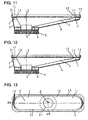
- Fig. 11 shows a sectional shape in two directions, lengthwise and widthwise directions, of edge 1 bonded to the diaphragm 2 of the loudspeaker in the present example.
- the flexible portion 11 of an edge made of foamed resin mainly based on polyurethane resin is formed to have corrugated sections with narrow concave corrugations and convex corrugations alternately arranged.
- a non-linearity of concave corrugations compensates a non-linearity of convex corrugations, thereby decreasing a level of nonlinear distortion in a case of small amplitude.
- Fig. 12 shows a modification of the present example, showing a sectional shape viewed in two directions of the edge 1.
- the sectional shape in the radial direction of the edge 1 made of foamed resin mainly based on polyurethane resin is formed to have a corrugated shape as the same in the present example.
- the sectional shape of the edge 1 is formed such that a thickness of the inner periphery portion 12 side bonded to the diaphragm 2 is thinner, and a thickness of the outer periphery portion 13 side is thicker.
- this modification decreases the level of nonlinear distortion, and as the same in Example 1, it also increases the efficiency at the medium and high frequency range sounds, and further, greatly contributes to improve the frequency characteristics, nonlinear distortion characteristics, and transient characteristics.
- Fig. 13 is a top view of a loudspeaker in the present Example.
- Fig. 14 shows a sectional shape in two directions of AO and BO in Fig. 13.
- a plurality of rib-shaped convex portions (ribs) 15 are provided in radial direction by increasing resin thickness so as to change the compliance of the edge.
- the convex portions 15 are intended to prevent a resonance and deformation of the diaphragm by balancing with the lengthwise stiffness of the diaphragm 2 and to improve the frequency characteristics.
- possible modifications include a structure in which the edge material is formed thinner at the inner periphery portion 12 side and thicker at the outer periphery portion 13 side, a structure in which a height of the ribs 15 or an effective thickness of edge portion including the height of rib 15 is thinner at the inner periphery portion 12 side and thicker at the outer periphery portion 13 side, and other various modifications.
- Fig. 15 is a top view of a loudspeaker of the present example.
- Fig. 16 shows a sectional view in two directions of AO and BO of the loudspeaker in Fig. 15.
- rib-shaped convex portions (rib) 16 increased in thickness of resin along the peripheral direction are partially provided in order to change the compliance of the edge.
- This structure is intended to prevent the resonance and deformation of the diaphragm by balancing with the lengthwise stiffness of the diaphragm 2 and to improve the frequency characteristics.
- a possible example of modification is such that a thickness of edge material or an effective thickness of edge portion including the height of the rib is formed thinner at the inner periphery portion 12 side and thicker at the outer periphery portion 13 side.
- Fig. 17 shows a sectional view in two directions, lengthwise and widthwise directions, of a loudspeaker in the present example.
- the flexible portion 11 of the edge made of foamed resin mainly based on polyurethane resin, as the same in Example 1, is partially changed in edge compliance in accordance with a change in the stiffness of the diaphragm.
- a thickness of the flexible portion 11 of the edge is increased in the lengthwise direction and a thickness is decreased in the widthwise direction, and the flexible portion 11 is formed so as to smoothly change in thickness.
- This structure is intended to prevent the resonance and deformation of the diaphragm by balancing with the lengthwise stiffness of the diaphragm 2 and to improve the frequency characteristics.
- a possible example of modification is such that the structure of the present embodiment is combined with a structure wherein the substantial thickness of edge portion is formed thinner at the inner periphery portion 12 side and thicker at the outer periphery portion 13 side.
- Fig. 18 is an enlarged sectional view showing a combined structure of diaphragm 2 and edge 1 which are.essential portions of the loudspeaker in the present example.
- a foaming thermosetting composition a raw material of the edge 1, is placed in the molding die and is molded under heat, the diaphragm 2 is insert-molded to combine the edge 1 and the diaphragm 2.
- the present invention is not limited to the above structures.
- an edge mainly using foamed urethane resin has been described.
- the edge material is not limited to such material, and it is also possible to use thermoplastic elastomers, rubbers, and the like.
- thermoplastic elastomers, rubbers, and the like thermoplastic elastomers, rubbers, and the like.
- the speaker of the present invention that is, the loudspeaker employing a diaphragm support mechanism, or an edge
- the edge having a structure where the inner periphery side is thinner and the outer periphery side is thicker has low mechanical impedance against the diaphragm and bad influences on the vibration mode of the diaphragm are decreased.
- the vibration energy is absorbed by the thick portion of the outer periphery portion, thus the standing waves of the diaphragm is suppressed, and the efficiency of medium and high frequency range sounds radiated from the loudspeaker is increased, and further, the structure greatly contributes to improve frequency characteristics, nonlinear distortion characteristics, and transient characteristics.
Landscapes
- Engineering & Computer Science (AREA)
- Multimedia (AREA)
- Physics & Mathematics (AREA)
- Acoustics & Sound (AREA)
- Signal Processing (AREA)
- Diaphragms For Electromechanical Transducers (AREA)
Applications Claiming Priority (1)
| Application Number | Priority Date | Filing Date | Title |
|---|---|---|---|
| PCT/JP2002/006431 WO2004004410A1 (ja) | 2002-06-26 | 2002-06-26 | スピーカエッジ |
Publications (2)
| Publication Number | Publication Date |
|---|---|
| EP1517582A1 true EP1517582A1 (de) | 2005-03-23 |
| EP1517582A4 EP1517582A4 (de) | 2009-01-14 |
Family
ID=29808154
Family Applications (1)
| Application Number | Title | Priority Date | Filing Date |
|---|---|---|---|
| EP02738805A Withdrawn EP1517582A4 (de) | 2002-06-26 | 2002-06-26 | Lautsprecherrand |
Country Status (9)
| Country | Link |
|---|---|
| US (1) | US7480390B2 (de) |
| EP (1) | EP1517582A4 (de) |
| JP (1) | JPWO2004004410A1 (de) |
| KR (1) | KR100678814B1 (de) |
| CN (1) | CN1628484B (de) |
| AU (1) | AU2002313267A1 (de) |
| MY (1) | MY140429A (de) |
| TW (1) | TWI236305B (de) |
| WO (1) | WO2004004410A1 (de) |
Cited By (2)
| Publication number | Priority date | Publication date | Assignee | Title |
|---|---|---|---|---|
| WO2009120512A1 (en) * | 2008-03-28 | 2009-10-01 | Bose Corporation | Loudspeaker suspension |
| EP3008917B1 (de) * | 2013-06-14 | 2021-12-22 | Genelec OY | Aufhängungselement zur aufhängung der membran eines lautsprechertreibers an dessen lautsprecherkorb sowie treiber und lautsprecher damit |
Families Citing this family (34)
| Publication number | Priority date | Publication date | Assignee | Title |
|---|---|---|---|---|
| ATE394895T1 (de) * | 2003-08-19 | 2008-05-15 | Matsushita Electric Industrial Co Ltd | Lautsprecher |
| TW200528925A (en) * | 2004-02-20 | 2005-09-01 | Hon Hai Prec Ind Co Ltd | A manufacturing method of a light guide plate |
| US7416047B2 (en) * | 2004-04-29 | 2008-08-26 | Ewald Frasl | Diaphragm for a loudspeaker with a moving coil |
| JP4560372B2 (ja) * | 2004-10-27 | 2010-10-13 | パイオニア株式会社 | スピーカ装置 |
| US7706560B2 (en) | 2004-10-27 | 2010-04-27 | Pioneer Corporation | Speaker apparatus |
| JP2008048300A (ja) * | 2006-08-21 | 2008-02-28 | Matsushita Electric Ind Co Ltd | スピーカとそれに用いられるスピーカ用エッジ |
| KR100811778B1 (ko) | 2007-02-27 | 2008-03-07 | 에스텍 주식회사 | 스피커 |
| US7931115B2 (en) * | 2007-05-31 | 2011-04-26 | Bose Corporation | Diaphragm surrounding |
| US8131001B2 (en) * | 2007-08-07 | 2012-03-06 | Onkyo Corporation | Speaker diaphragm and electrodynamic loudspeaker using the same |
| JP4771555B2 (ja) * | 2007-08-07 | 2011-09-14 | オンキヨー株式会社 | スピーカー振動板およびこれを用いた動電型スピーカー |
| CN101365254B (zh) * | 2007-08-10 | 2012-02-29 | 日本胜利株式会社 | 音响振动板及扬声器 |
| US20090169049A1 (en) * | 2007-12-28 | 2009-07-02 | Szu-Wei Sun | Low Profile Audio Speaker |
| KR100993242B1 (ko) * | 2009-02-04 | 2010-11-10 | 에스텍 주식회사 | 스피커 |
| JP2011211573A (ja) * | 2010-03-30 | 2011-10-20 | Panasonic Corp | スピーカ用振動板及びこれを用いたスピーカ |
| JP2011211572A (ja) * | 2010-03-30 | 2011-10-20 | Panasonic Corp | スピーカ用振動板及びこれを用いたスピーカ |
| US8295537B2 (en) * | 2010-03-31 | 2012-10-23 | Bose Corporation | Loudspeaker moment and torque balancing |
| US8295536B2 (en) * | 2010-03-31 | 2012-10-23 | Bose Corporation | Moving magnet levered loudspeaker |
| US8540049B2 (en) * | 2010-12-23 | 2013-09-24 | Bose Corporation | Acoustic diaphragm suspending |
| CN102118672A (zh) * | 2011-03-28 | 2011-07-06 | 苏州上声电子有限公司 | 扬声器振动膜片及扬声器 |
| GB2491108B (en) * | 2011-05-18 | 2014-06-04 | Gp Acoustics Uk Ltd | Loudspeaker |
| EP2803205A1 (de) * | 2012-01-09 | 2014-11-19 | Harman International Industries, Incorporated | Lautsprecherhorn |
| US8397861B1 (en) | 2012-03-02 | 2013-03-19 | Bose Corporation | Diaphragm surround |
| US9055370B2 (en) | 2012-08-31 | 2015-06-09 | Bose Corporation | Vibration-reducing passive radiators |
| CN202873041U (zh) * | 2012-09-26 | 2013-04-10 | 瑞声光电科技(常州)有限公司 | 复合振膜及应用所述复合振膜的扬声器 |
| CN202873039U (zh) * | 2012-09-26 | 2013-04-10 | 瑞声光电科技(常州)有限公司 | 复合振膜及应用所述复合振膜的扬声器 |
| US9253576B2 (en) * | 2013-11-21 | 2016-02-02 | Bose Corporation | Suspension for acoustic device |
| FR3035295B1 (fr) * | 2015-04-15 | 2017-04-21 | Focal Jmlab | Dispositif de suspension pour haut-parleur, procede de fabrication et haut-parleur associes |
| GB201513555D0 (en) * | 2015-07-31 | 2015-09-16 | Pss Belgium Nv | Audio system |
| CN206923018U (zh) * | 2017-06-20 | 2018-01-23 | 瑞声科技(新加坡)有限公司 | 音膜、发声器件和电子设备 |
| JP7338474B2 (ja) * | 2017-12-07 | 2023-09-05 | ソニーグループ株式会社 | 振動系、スピーカ装置及び映像表示装置 |
| CN209358770U (zh) * | 2018-06-15 | 2019-09-06 | 深圳市韶音科技有限公司 | 一种骨传导扬声器及耳机 |
| CN109218935B (zh) * | 2018-08-07 | 2024-02-20 | 张永春 | 矩形圆角定心支片及扬声器 |
| CN113542989B (zh) * | 2020-04-17 | 2023-09-22 | 歌尔股份有限公司 | 一种振膜以及微型发声装置 |
| IT202300014307A1 (it) * | 2023-07-10 | 2025-01-10 | Faital S P A | Altoparlante con diaframma di forma non circolare e sospensione bilanciata |
Family Cites Families (24)
| Publication number | Priority date | Publication date | Assignee | Title |
|---|---|---|---|---|
| US3645356A (en) * | 1969-12-26 | 1972-02-29 | Nippon Musical Instruments Mfg | Loudspeaker |
| JPS5834383B2 (ja) | 1974-07-23 | 1983-07-26 | セキスイカセイヒンコウギヨウ カブシキガイシヤ | シ−トノ マキトリホウホウオヨビ ソウチ |
| JPS5925519B2 (ja) | 1977-04-07 | 1984-06-18 | 株式会社日立製作所 | スピ−カの製造方法 |
| JPS58221597A (ja) * | 1982-06-17 | 1983-12-23 | Matsushita Electric Ind Co Ltd | 動電型スピ−カ |
| JPH01272300A (ja) * | 1988-04-22 | 1989-10-31 | Matsushita Electric Ind Co Ltd | スピーカシステム |
| JPH03247099A (ja) | 1990-02-23 | 1991-11-05 | Sharp Corp | スピーカ |
| JPH05122791A (ja) * | 1991-10-28 | 1993-05-18 | Matsushita Electric Ind Co Ltd | スピーカ用エツジ |
| US6171534B1 (en) * | 1992-01-15 | 2001-01-09 | Patrick Arthur Leach | Method of making a speaker cone and surround assembly |
| DE69332123T2 (de) * | 1992-02-21 | 2003-03-20 | Matsushita Electric Industrial Co., Ltd. | Lautsprechersystem |
| JP2884882B2 (ja) | 1992-02-21 | 1999-04-19 | 松下電器産業株式会社 | スピーカ |
| JP3049936B2 (ja) | 1992-05-07 | 2000-06-05 | 松下電器産業株式会社 | 楕円形スピーカ |
| JP3064695B2 (ja) * | 1992-10-14 | 2000-07-12 | 松下電器産業株式会社 | スピーカ |
| JPH06315194A (ja) | 1993-04-28 | 1994-11-08 | Matsushita Electric Ind Co Ltd | スピーカ |
| JP4088983B2 (ja) * | 1996-10-16 | 2008-05-21 | 松下電器産業株式会社 | スピーカ |
| US20030068064A1 (en) * | 2001-10-09 | 2003-04-10 | Czerwinski Eugene J. | Neoprene surround for an electro-dynamic acoustical transducer |
| EP0963136B1 (de) * | 1998-05-08 | 2011-08-31 | Panasonic Corporation | Lautsprecher |
| JP2000261885A (ja) * | 1999-03-09 | 2000-09-22 | Inoac Corp | スピーカエッジ |
| US6611604B1 (en) * | 1999-10-22 | 2003-08-26 | Stillwater Designs & Audio, Inc. | Ultra low frequency transducer and loud speaker comprising same |
| JP2001189990A (ja) * | 1999-12-28 | 2001-07-10 | Jsp Corp | スピーカー振動板用素材及びスピーカー振動板 |
| US7548631B2 (en) * | 2000-01-19 | 2009-06-16 | Harman International Industries, Incorporated | Speaker surround structure for maximizing cone diameter |
| US6700987B2 (en) * | 2000-08-25 | 2004-03-02 | Matsushita Electric Industrial Co., Ltd. | Loudspeaker |
| JP3491087B2 (ja) * | 2000-10-26 | 2004-01-26 | 松下電器産業株式会社 | スピーカエッジとその発泡成形方法及びその発泡成形装置及びスピーカエッジ発泡成形システムならびに当該スピーカエッジを用いたスピーカ |
| GB2374753B (en) * | 2001-01-29 | 2004-12-22 | Goodmans Loudspeakers Ltd | Loudspeaker suspension |
| JP2002374593A (ja) * | 2001-06-18 | 2002-12-26 | Pioneer Electronic Corp | スピーカ振動板 |
-
2002
- 2002-06-26 AU AU2002313267A patent/AU2002313267A1/en not_active Abandoned
- 2002-06-26 EP EP02738805A patent/EP1517582A4/de not_active Withdrawn
- 2002-06-26 US US10/517,261 patent/US7480390B2/en not_active Expired - Lifetime
- 2002-06-26 CN CN028291964A patent/CN1628484B/zh not_active Expired - Fee Related
- 2002-06-26 WO PCT/JP2002/006431 patent/WO2004004410A1/ja not_active Ceased
- 2002-06-26 KR KR1020047021204A patent/KR100678814B1/ko not_active Expired - Fee Related
- 2002-06-26 JP JP2004517207A patent/JPWO2004004410A1/ja active Pending
-
2003
- 2003-06-17 MY MYPI20032260A patent/MY140429A/en unknown
- 2003-06-24 TW TW092117105A patent/TWI236305B/zh not_active IP Right Cessation
Cited By (3)
| Publication number | Priority date | Publication date | Assignee | Title |
|---|---|---|---|---|
| US8139812B2 (en) | 2004-11-19 | 2012-03-20 | Subarna Basnet | Loudspeaker suspension |
| WO2009120512A1 (en) * | 2008-03-28 | 2009-10-01 | Bose Corporation | Loudspeaker suspension |
| EP3008917B1 (de) * | 2013-06-14 | 2021-12-22 | Genelec OY | Aufhängungselement zur aufhängung der membran eines lautsprechertreibers an dessen lautsprecherkorb sowie treiber und lautsprecher damit |
Also Published As
| Publication number | Publication date |
|---|---|
| CN1628484A (zh) | 2005-06-15 |
| AU2002313267A8 (en) | 2004-01-19 |
| KR100678814B1 (ko) | 2007-02-05 |
| JPWO2004004410A1 (ja) | 2005-11-04 |
| KR20050010972A (ko) | 2005-01-28 |
| MY140429A (en) | 2009-12-31 |
| EP1517582A4 (de) | 2009-01-14 |
| TWI236305B (en) | 2005-07-11 |
| US20050226456A1 (en) | 2005-10-13 |
| WO2004004410A1 (ja) | 2004-01-08 |
| US7480390B2 (en) | 2009-01-20 |
| TW200404475A (en) | 2004-03-16 |
| AU2002313267A1 (en) | 2004-01-19 |
| CN1628484B (zh) | 2010-12-15 |
Similar Documents
| Publication | Publication Date | Title |
|---|---|---|
| US7480390B2 (en) | Loudspeaker edge | |
| CN1692676B (zh) | 悬架及使用其的电声变换装置 | |
| US8199962B2 (en) | Loudspeaker diaphragm and loudspeaker using the same | |
| EP0920785B1 (de) | Lautsprechersantriebeinheiten | |
| JP2692040B2 (ja) | 小型電気音響変換器 | |
| EP1711031B1 (de) | Membran für einen lautsprecher und lautsprecher | |
| US8131001B2 (en) | Speaker diaphragm and electrodynamic loudspeaker using the same | |
| US8135164B2 (en) | Speaker | |
| WO2009107192A1 (ja) | 音響変換器用振動体及びスピーカ装置 | |
| US6863153B1 (en) | Loudspeaker diaphragm | |
| CN1951149B (zh) | 扬声器 | |
| CN110972034B (zh) | 一种振膜及发声装置 | |
| JP2002218585A (ja) | スピーカ | |
| CN117768824A (zh) | 一种激励器及车载音响系统 | |
| JP4134419B2 (ja) | スピーカ | |
| CN221633942U (zh) | 一种激励器及车载音响系统 | |
| JP4596969B2 (ja) | 振動板及びこれを用いたスピーカユニット | |
| JP2007151032A (ja) | スピーカ装置およびこのスピーカ装置が取り付けられる電子機器 | |
| JP3896945B2 (ja) | サスペンションおよびこれを用いた電気音響変換装置 | |
| JPS5942794Y2 (ja) | ド−ム型スピ−カ− | |
| KR102028854B1 (ko) | 진동판 | |
| KR0177684B1 (ko) | 스피커의 공진흡수장치 | |
| JPH0326716Y2 (de) | ||
| JP2003304594A (ja) | 高音用スピーカ | |
| HK1019987B (en) | Loudspeaker drive units |
Legal Events
| Date | Code | Title | Description |
|---|---|---|---|
| PUAI | Public reference made under article 153(3) epc to a published international application that has entered the european phase |
Free format text: ORIGINAL CODE: 0009012 |
|
| 17P | Request for examination filed |
Effective date: 20041209 |
|
| AK | Designated contracting states |
Kind code of ref document: A1 Designated state(s): AT BE CH CY DE DK ES FI FR GB GR IE IT LI LU MC NL PT SE TR |
|
| AX | Request for extension of the european patent |
Extension state: AL LT LV MK RO SI |
|
| DAX | Request for extension of the european patent (deleted) | ||
| RBV | Designated contracting states (corrected) |
Designated state(s): DE FR GB |
|
| RAP1 | Party data changed (applicant data changed or rights of an application transferred) |
Owner name: MATSUSHITA ELECTRIC INDUSTRIAL CO., LTD. |
|
| RAP1 | Party data changed (applicant data changed or rights of an application transferred) |
Owner name: PANASONIC CORPORATION |
|
| A4 | Supplementary search report drawn up and despatched |
Effective date: 20081211 |
|
| STAA | Information on the status of an ep patent application or granted ep patent |
Free format text: STATUS: THE APPLICATION IS DEEMED TO BE WITHDRAWN |
|
| 18D | Application deemed to be withdrawn |
Effective date: 20090706 |