EP1517218A2 - Fahrbarer Aufbewahrungsbehälter - Google Patents
Fahrbarer Aufbewahrungsbehälter Download PDFInfo
- Publication number
- EP1517218A2 EP1517218A2 EP04019784A EP04019784A EP1517218A2 EP 1517218 A2 EP1517218 A2 EP 1517218A2 EP 04019784 A EP04019784 A EP 04019784A EP 04019784 A EP04019784 A EP 04019784A EP 1517218 A2 EP1517218 A2 EP 1517218A2
- Authority
- EP
- European Patent Office
- Prior art keywords
- storage container
- chassis
- mobile
- mobile storage
- drive belt
- Prior art date
- Legal status (The legal status is an assumption and is not a legal conclusion. Google has not performed a legal analysis and makes no representation as to the accuracy of the status listed.)
- Granted
Links
Images


Classifications
-
- G—PHYSICS
- G06—COMPUTING OR CALCULATING; COUNTING
- G06F—ELECTRIC DIGITAL DATA PROCESSING
- G06F1/00—Details not covered by groups G06F3/00 - G06F13/00 and G06F21/00
- G06F1/16—Constructional details or arrangements
- G06F1/18—Packaging or power distribution
- G06F1/181—Enclosures
- G06F1/182—Enclosures with special features, e.g. for use in industrial environments; grounding or shielding against radio frequency interference [RFI] or electromagnetical interference [EMI]
-
- B—PERFORMING OPERATIONS; TRANSPORTING
- B62—LAND VEHICLES FOR TRAVELLING OTHERWISE THAN ON RAILS
- B62B—HAND-PROPELLED VEHICLES, e.g. HAND CARTS OR PERAMBULATORS; SLEDGES
- B62B5/00—Accessories or details specially adapted for hand carts
- B62B5/02—Accessories or details specially adapted for hand carts providing for travelling up or down a flight of stairs
- B62B5/025—Accessories or details specially adapted for hand carts providing for travelling up or down a flight of stairs with gliding elements, e.g. skids
-
- B—PERFORMING OPERATIONS; TRANSPORTING
- B62—LAND VEHICLES FOR TRAVELLING OTHERWISE THAN ON RAILS
- B62B—HAND-PROPELLED VEHICLES, e.g. HAND CARTS OR PERAMBULATORS; SLEDGES
- B62B2202/00—Indexing codes relating to type or characteristics of transported articles
- B62B2202/30—Furniture
Definitions
- the invention relates to a mobile storage container after the Preamble of claim 1.
- this Storage cabinet can store a number of mobile computers which will be reloaded during storage. Furthermore can on the storage cabinet more peripheral devices, such as Example printer, scanner, etc., set up and connected. The Coupling to the computers, which can be removed from the storage cabinet can be done via infrared or radio.
- Such a storage cabinet has the goal, a common classroom, a seminar room or another classroom in a computer room turn.
- the known storage cabinet in the driven selected room and the individual mobile computers are off taken from the storage cabinet and at the respective user place established.
- the single mobile computer via the wireless interfaces with the printer in the Storage cabinet are connected.
- Such a storage system is the conventionally known computer rooms replace that constantly by a hard-wired arrangement of several computers are occupied and therefore can not be used for any other purpose.
- an adjustable table for a computer system which has a telescopic, sloping base and the Base part is mounted on rollers. Disadvantage is that here no separate drive is arranged, which moves the table automatically and optionally Height differences (steps) overcomes.
- DE 33 16 896 A1 is a mobile equipment cart for electronic devices discloses which comprises an upper part, side parts and lower part with driving rollers and can be dismantled for possible transport. Disadvantage is that this Equipment cart also has no drive for automatic movement and not suitable for transport by stairs.
- the object of the invention is therefore to provide an easily transportable, propose staircase suitable storage system, with which it is possible is to use any room in a building for computer training purposes to reach.
- An essential feature of the invention is that the chassis at least one circumferentially driven drive belt is arranged, with his bottom side strand rests on the ground and over at its ends in each case at least one deflection roller is folded.
- the mobile storage container consists essentially of a Chassis, which has at least one stand with the Storage container is connected.
- the invention provides for the mobility of the storage system so far Increase that storage system also using appropriate stairs can be easily transported to high or low lying rooms.
- the chassis is stair climbing and at least one circumferentially driven toothed belt in the chassis is arranged, which rests with its bottom strand on the floor and folded over at both ends of the chassis via a respective pulley becomes.
- One of these pulleys is driven, or it may be a separate Drive roller be present, which drives the toothed belt.
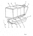
- the base is designed as a tilting foot so as to Focus the storage box forward toward the stairs to move. In this way, too high a supine position of the Storage container avoided and a danger of falling on the stairs prevented.
- this embodiment of the invention are in Rear area still attached additional castors, which left and right of the Drive belt are arranged.
- these castors are between the center drive belt and the two left and right of it arranged skids. It suffice ever a castor left and right of Drive belt, but more than ever a steering roller can be provided there be.
- the castors are in particular freely rotatable about their vertical axes and therefore steerable, so that then the entire storage container in the way of a Shopping cart is steerable.
- the castors are in and out of the chassis swing out and get in or out of contact with the ground.
- An ideal embodiment of the storage container of the present invention thus includes a longitudinally aligned central bottom drive belt that extends over the entire or at least one Much of the length of the storage box extends, continues left and to the right of each an outer skid and between the central drive belt and the outer skids each have a steering roller in the rear rear area, wherein the Swivel castors can be moved in and out as required, in other words then for plane travel Contact with the ground, then have no ground contact for the staircase.
- the batteries are located in the chassis are.
- the Storage container is modular expandable.
- the storage container is designed to be telescopic. This is achieved by the storage container of several nestable housing shells on two in parallel Distance juxtaposed frame rails arranged displaceably are.
- This modular extensibility is particularly favorable because the number of there stored notebook space is arbitrarily expandable.
- the extensibility of the housing shells is also important to good accessibility in the interior of the storage container too create.
- the slots for charging each second Batteries of each notebook are arranged and above the notebooks are plugged in yourself. These notebooks can each side from the corresponding storage slots in the storage container on and be unplugged.
- the devices are also wired together and functional together connected so that the storage box taken on its own is also able to work. It requires no additional wiring, none additional connection of peripherals, since all necessary equipment in the storage container itself can be integrated.
- the invention provides that on one of the outer sides of the Storage container corresponding peripheral interfaces are arranged, about the example of a digital camera, an audio system or others Any additional modules can be connected.
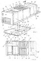
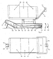
- the mobile storage container according to the invention consists according to FIG. 1 essentially from a lower, bottom-side chassis 1, a via a coupling fitting 4 attached thereto base 3 and one on a Another coupling fitting 4 attached thereto storage container. 2
- the invention is not limited to the arrangement of a single stand 3. It can also several feet parallel to each other on the chassis 1 be arranged.
- the top of the chassis 1 is formed by a cover 6, which covers the drive unit arranged therein.
- a cover 6 which covers the drive unit arranged therein.
- a total of three front Deflection rollers 7, 8 are arranged, wherein only the front guide rollers 7, 8 are shown.
- the outer deflection rollers 7 are passively formed, that is they are rotatably mounted in the chassis 1 and are of a sliding belt. 9 each encompassed, the same rear pulleys 7 on the chassis. 1 is diverted.
- the slide belt 9 is thus a circumferential Bandtrum, which with his Boden mineralen Trum rests on the floor and so a sliding surface for the Chassis 1 forms.
- a front and a rear, rotatably driven pulley 8 is arranged, each of which as a Bandtrum trained timing belt 10 is looped.
- Timing belt for driving the Timing belt is still a separate drive roller is used.
- the drive of the toothed belt is not shown in detail. He exists in essential of a drive motor, and an associated Energy supply, in particular a battery.
- the front part of the chassis 1 is by an obliquely upward Skid 11 formed so that the rotationally driven toothed belt 10 according to FIG 5 with its sloping surface when driving on a stair 37 steps Grasp edge and pull up over the step.
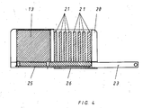
- the storage container 2 consists of an approximately box-shaped container, which consists of several telescoping housing shells.
- a fixed housing shell 25 - which according to Figure 3 outboard is arranged - are two inner housing 26, 27 arranged movable.
- a printer 13 is arranged, on which a scanner 14 is arranged. It is also an antenna 16 provided for the radio connection to the individual notebooks 21, and a associated radio station 17 is also in the front part of the housing shell 25 arranged.
- a digital projector 20 having a front projection lens 19 provided, and at the front part of the housing shell 25 is an interface 18th intended for connection of peripheral devices.
- the power supply 15 is arranged in the chassis 1.
- the housing shell 26 is preferably made of a transparent plastic material trained to the arrangement of the individual, behind it plugged in notebooks 21 to allow.
- the Housing shell 26, for example, in the direction of arrow 12 on the inner Housing shell 27 can be moved, and it can also be reversed this be moved to the place of the housing shell 26 '.
- connection board 22 can still connector 34 for the Inserting reserve batteries 33 are provided so that reserve batteries for the respective notebook 21 can be used.
- FIG. 3 shows that the frame members 23 are approximately U-shaped are formed, in the interior of which the rollers 31 for the displacement drive of Housing shells 26, 27 run. Each roller is rotatable on an associated one Axis 30 mounted, and the respective axis 30 is connected to the housing shell 26 or the housing shell 27 respectively connected.
- the rear ends of the two frame members 23 are provided with a push bar 24th connected, so that the entire storage system in the manner of a Wheelbarrow can be moved.
- a Audio system 28 is arranged in the rear part of the housing shell 26 .
- the direction of arrow 29 is the telescoping of the individual housing shells 26, 26 'to each other.
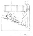
- Figure 5 now shows the stair climbing ability of the entire mobile Storage container.
- the base 3 in the chassis a tilting axis 36th training, so that the stand is tilted obliquely forward.
- FIG. 5 now shows the simple transportability of the entire system Storage container.
- the user only needs the rear push bar 24 grab and drive the device towards a front step 37, until the front edge of the toothed belt 10 is engaged with the lowermost Stair step 37 arrives. Then pulls the chassis 1 through the Rotary drive of the toothed belt 10 over all other steps, whereby a particularly simple transport is possible.
- This wheelbarrow-like transport is a particularly simple and inexpensive form of transport. It is known that such a device It has a relatively heavy weight, which prevents a person from still using the system can carry. When carried by several people is the portability severely limited when it comes to overcoming narrow staircases. For this reason, the invention sees the wheelbarrow-like transport system with a stair-climbing chassis, which also transport through narrow and steep staircases allows.
- the wheelbarrow-like design of the chassis also has the advantage that regardless of the drive of the chassis a particularly light Transportability is given. Already when driving over steps or Thresholds (threshold or door stops) succeed in such heavy Storage containers no longer, these without lifting over the threshold to transport. This is achieved with the invention by the wheelbarrow-like solution in that in the front area of the chassis corresponding Transfer rollers are arranged when lifting the storage container overcome the threshold.
- the chassis 75 in its simplest embodiment has at least two steerable rollers 55 in the rear area, as well as a middle drive belt 72nd and left and right of each a slide rail 74th
- FIGS 6 to 10 show a Treppensiereaugliches storage system, where it can be seen that a chassis 75 has lateral slide rails 74 and between a drive body is arranged, which consists essentially of a in Arrow direction 73 and in the opposite direction drivable drive belt 72nd is, wherein this drive belt 72 according to Figure 7 corresponding projections, Nubs or ribs has, so on a height offset edge of a staircase attack and raise the entire chassis 75 over that edge of the stairs to transport.
- the entire storage system can climb a staircase or be driven down from this staircase.
- a handle 76th arranged on the one or more control panels 71 for the electrical Drives and the like are provided.
- the control panels 71 include at least one on / off switch, an emergency stop button and a Switch for forward / reverse travel.
- the center in the longitudinal direction of the storage system extending Drive belt 72 is guided over three pulleys 68-70 and is replaced by a displaceable tension roller 67 held in the tensioned state.
- the foremost Guide roller 68 is arranged much higher than the other two Deflection rollers 69, 70, so that the drive belt 72 in the front area a runner 59th has and runs at an angle 66 to the bottom 65 of the drive belt 72, which is the Getting on and off on and off stairs made easier.
- the storage system is first with extended castors 55 in Position brought in front of the stairs, then both castors 55 retracted until this over the runners 74 and the drive belt 72 in the chassis 75 itself and then the storage system on the entire drive belt 72 rests and possibly on the skids 74. Thereafter, the Storage system via the drive belt 72 driven on the stairs be driven and thanks to the two skids 74 left and right of Drive belts 72 as lateral stabilization over the stairs to the next level Be driven level on which then the castors 55 in turn extended so that the storage system is steerable.
Landscapes
- Engineering & Computer Science (AREA)
- Theoretical Computer Science (AREA)
- Physics & Mathematics (AREA)
- Mechanical Engineering (AREA)
- Power Engineering (AREA)
- Human Computer Interaction (AREA)
- General Engineering & Computer Science (AREA)
- General Physics & Mathematics (AREA)
- Computer Hardware Design (AREA)
- Chemical & Material Sciences (AREA)
- Combustion & Propulsion (AREA)
- Transportation (AREA)
- Electromagnetism (AREA)
- Handcart (AREA)
- Motorcycle And Bicycle Frame (AREA)
- Centrifugal Separators (AREA)
- Crystals, And After-Treatments Of Crystals (AREA)
- Electron Tubes For Measurement (AREA)
- Stackable Containers (AREA)
- Details Of Rigid Or Semi-Rigid Containers (AREA)
- Warehouses Or Storage Devices (AREA)
- Packages (AREA)
- Containers And Packaging Bodies Having A Special Means To Remove Contents (AREA)
- Table Devices Or Equipment (AREA)
Abstract
Description
- Figur 1:
- perspektivische Ansicht des fahrbaren Aufbewahrungsbehälter in der Grundstellung;
- Figur 2:
- Draufsicht auf die Anordnung nach Figur 1;
- Figur 3:
- Querschnitt durch den Aufbewahrungsbehälter;
- Figur 4:
- einen Längsschnitt durch den Aufbewahrungsbehälter nach Figur 1;
- Figur 5:
- die Steigfunktion des Aufbewahrungsbehälters beim Überfahren einer Treppe;
- Figur 6:
- Zu den Figuren 1-5 alternative Ausführungsform eines treppentauglichen Aufbewahrungsbehälters in einer perspektivischen Darstellung;
- Figur 7:
- Aufbewahrungsbehälter nach Figur 6 in Vorderansicht;
- Figur 8:
- Aufbewahrungsbehälter nach Figur 6 in Unteransicht;
- Figur 9:
- Aufbewahrungsbehälter nach Figur 6 in einer Seitenansicht;
- Figur 10:
- Aufbewahrungsbehälter nach Figur 6 in einer Draufsicht.
- 1
- Fahrgestell
- 2
- Aufbewahrungsbehälter
- 3
- Standfuß
- 4
- Kupplungsbeschlag
- 5
- -
- 6
- Abdeckhaube
- 7
- Umlenkrolle (passiv)
- 8
- Umlenkrolle (angetrieben)
- 9
- Gleitriemen
- 10
- Zahnriemen
- 11
- Kufe
- 12
- Pfeilrichtung
- 13
- Drucker
- 14
- Scanner
- 15
- Netzteil
- 16
- Antenne
- 17
- Funkstation
- 18
- Schnittstelle
- 19
- Projektionslinse
- 20
- Digitalprojektor
- 21
- Notebooks
- 22
- Verbindungsplatine
- 23
- Rahmenholm
- 24
- Schubbügel
- 25
- Gehäuseschale (außen)
- 26
- Gehäuseschale (innen) 26'
- 27
- Gehäuseschale (innen)
- 28
- Audio-System
- 29
- Pfeilrichtung
- 30
- Achse
- 31
- Rolle
- 32
- T-Ankerschiene
- 33
- Akku
- 34
- Anschlussstecker
- 35
- Pfeilrichtung
- 36
- Kippachse
- 37
- Treppenstufe
- 38
- Steckanschluss
- 39
- -
- 40
- -
- 41
- -
- 42
- -
- 43
- -
- 44
- Haube
- 45
- Haube
- 46
- -
- 47
- -
- 48
- Haube
- 49
- -
- 50
- -
- 51
- -
- 52
- -
- 53
- Stützfuß
- 54
- -
- 55
- lenkbare Laufrolle (Lenkrolle)
- 56
- -
- 57
- -
- 58
- -
- 59
- Kufe
- 60
- Aufbewahrungsbehälter
- 61
- vorderer Bereich von 72
- 62
- Ausschwenkrichtung von 55
- 63
- Einschwenkrichtung von 55
- 64
- Elektromotor
- 65
- Bodentrum
- 66
- Winkel
- 67
- Spannrolle
- 68
- Umlenkrolle
- 69
- Umlenkrolle
- 70
- Umlenkrolle
- 71
- Bedienungskonsole
- 72
- Antriebsband
- 73
- Pfeilrichtung
- 74
- Gleitschiene
- 75
- Fahrgestell
- 76
- Handgriff
Claims (17)
- Fahrbarer Aufbewahrungsbehälter (2, 60) für mobile Rechner und/oder periphere Geräte, mit einem fahrbaren Fahrgestell (1, 75), welches über mindestens einen Standfuß (3, 53) mit dem Aufbewahrungsbehälter (2, 60) verbunden ist, dadurch gekennzeichnet, dass am Fahrgestell (1, 75) mindestens ein umlaufend angetriebenes Antriebsband (10, 72) angeordnet ist, das mit seinem bodenseitigen Trum auf dem Untergrund aufliegt und an seinen Enden über jeweils mindestens eine Umlenkrolle (8; 68,70) umgelegt ist.
- Fahrbarer Aufbewahrungsbehälter (2, 60) nach Anspruch 1, dadurch gekennzeichnet, dass das Antriebsband (10, 72) als Zahnriemen ausgebildet ist.
- Fahrbarer Aufbewahrungsbehälter (2, 60) nach Anspruch 1, dadurch gekennzeichnet, dass das Antriebsband (10, 72) auf der äußeren Lauffläche Vorsprünge, Noppen oder Rippen hat, um so an einer höhenversetzten Kante einer Treppe anzugreifen und das gesamte Fahrgestell (1, 75) über diese Kante der Treppe hinauf zu befördern.
- Fahrbarer Aufbewahrungsbehälter (2, 60) nach Anspruch 1 bis 3, dadurch gekennzeichnet, dass mindestens ein mittig im Fahrgestell (75) angeordnetes Antriebsband (10, 72) vorgesehen ist und links und rechts davon mindestens je eine Gleitkufe (74) und/oder mindestens je ein Gleitband (9).
- Fahrbarer Aufbewahrungsbehälter (2, 60) nach Anspruch 4, dadurch gekennzeichnet, dass das mindestens je eine Gleitband (9) selbst nicht angetrieben ist, sondern an seinen Enden über jeweils mindestens eine Umlenkrolle (7) umgelegt ist, auf dem Untergrund aufliegt und passiv mitläuft.
- Fahrbarer Aufbewahrungsbehälter (2, 60) nach den Ansprüchen 1 bis 5, dadurch gekennzeichnet, dass in dem bodenseitigen Fahrgestell (1, 75) mindestens zwei lenkbare Rollen (55) im hinteren Heckbereich oder im vorderen Frontbereich angeordnet sind.
- Fahrbarer Aufbewahrungsbehälter (2, 60) nach Anspruch 6, dadurch gekennzeichnet, dass die lenkbaren Rollen (55) wiederholt aus der Außenkontur des Fahrgestells (75) ausschwenkbar sind, so dass die Rollen (55) auf dem Untergrund aufliegen, zusammen mit nur einem vorderen Bereich (61) oder hinteren Bereich des Antriebsbandes (72).
- Fahrbarer Aufbewahrungsbehälter (2, 60) nach den Ansprüchen 1 bis 7, dadurch gekennzeichnet, dass das Fahrgestell (1, 75) eine schräge Kufe (11, 59) am Fahrgestell (1) aufweist, über welche der Antriebsriemen (10) geleitet ist.
- Fahrbarer Aufbewahrungsbehälter (2, 60) nach den Ansprüchen 1 bis 8, dadurch gekennzeichnet, dass im Fahrgestell (1, 75) mindestens ein elektrisches Antriebsmittel (64) angeordnet ist, das mindestens eine der Rollen (7; 68-70) drehbar antreibt.
- Fahrbarer Aufbewahrungsbehälter (2, 60) nach den Ansprüchen 1 bis 9, dadurch gekennzeichnet, dass der Standfuß (3) als Kippfuß ausgebildet ist.
- Fahrbarer Aufbewahrungsbehälter (2, 60) nach den Ansprüchen 1 bis 10, dadurch gekennzeichnet, dass der Aufbewahrungsbehälter (2, 60) an seiner hinteren Seite einen Schubbügel (24, 76) aufweist und der gesamte Aufbewahrungsbehälter (2, 60) an dem Schubbügel (24, 76) heb- und kippbar ist.
- Fahrbarer Aufbewahrungsbehälter (2, 60) nach den Ansprüchen 1 bis 11, dadurch gekennzeichnet, dass die für den Antrieb des Fahrgestells notwendigen Antriebsbatterien (33) für einen niedrigen Schwerpunkt im Fahrgestell (1, 75) angeordnet sind.
- Fahrbarer Aufbewahrungsbehälter (2, 60) nach den Ansprüchen 1 bis 12, dadurch gekennzeichnet, dass der Aufbewahrungsbehälter (2, 60) aus mehreren, ineinander verschiebbaren, Gehäuseschalen (25-27; 44,45,48) besteht, die auf zwei in parallelem Abstand nebeneinander angeordneten Rahmenholmen (23) verschiebbar angeordnet sind und der Aufbewahrungsbehälter (2, 60) modular erweiterbar ist.
- Fahrbarer Aufbewahrungsbehälter (2, 60) nach den Ansprüchen 1 bis 13, dadurch gekennzeichnet, dass der Aufbewahrungsbehälters (2, 60) am Boden Steckplätze (38) für die Aufladung einer zweiten Batterie eines Notebooks (21) aufweist und die Notebooks (21) über Steckanschlüsse (38) mit einer Verbindungsplatine (22) verbunden sind, welche eine elektrische Verbindung zu den Notebooks (21) oder anderen Funktionsteilen herstellt.
- Fahrbarer Aufbewahrungsbehälter (2, 60) nach den Ansprüchen 1 bis 14, dadurch gekennzeichnet, dass an einer der Außenseiten des Aufbewahrungsbehälters (2, 60) mindestens eine Peripherieschnittstelle (18) für den Anschluss peripherer Geräte angeordnet ist.
- Aufbewahrungsbehälter (2, 60) nach den Ansprüchen 1 bis 15, dadurch gekennzeichnet, dass die Geräte miteinander verkabelt und funktionsfähig zusammen angeschlossen sind und dass der Aufbewahrungsbehälter (2, 60) für sich allein genommen arbeits- und funktionsfähig ist.
- Fahrbarer Aufbewahrungsbehälter (2, 60) nach den Ansprüchen 1 bis 16, dadurch gekennzeichnet, dass der Aufbewahrungsbehälter (2, 60) zur Aufnahme von Notebooks (21), Drucker (13), Scanner (14) und Digitalprojektoren für den mobilen Transport vorgesehen ist.
Priority Applications (1)
| Application Number | Priority Date | Filing Date | Title |
|---|---|---|---|
| EP04019784A EP1517218B1 (de) | 2003-08-21 | 2004-08-20 | Fahrbarer Aufbewahrungsbehälter |
Applications Claiming Priority (5)
| Application Number | Priority Date | Filing Date | Title |
|---|---|---|---|
| DE10338320 | 2003-08-21 | ||
| DE10338320A DE10338320B3 (de) | 2003-08-21 | 2003-08-21 | Fahrbarer Aufbewahrungsbehälter |
| EP04015097A EP1522915B1 (de) | 2003-08-21 | 2004-06-28 | Vorrichtung zum Ankoppeln von Rechnern an einer Trägereinheit |
| EP04015097 | 2004-06-28 | ||
| EP04019784A EP1517218B1 (de) | 2003-08-21 | 2004-08-20 | Fahrbarer Aufbewahrungsbehälter |
Publications (3)
| Publication Number | Publication Date |
|---|---|
| EP1517218A2 true EP1517218A2 (de) | 2005-03-23 |
| EP1517218A3 EP1517218A3 (de) | 2005-06-15 |
| EP1517218B1 EP1517218B1 (de) | 2006-08-02 |
Family
ID=36782488
Family Applications (1)
| Application Number | Title | Priority Date | Filing Date |
|---|---|---|---|
| EP04019784A Expired - Lifetime EP1517218B1 (de) | 2003-08-21 | 2004-08-20 | Fahrbarer Aufbewahrungsbehälter |
Country Status (5)
| Country | Link |
|---|---|
| EP (1) | EP1517218B1 (de) |
| AT (1) | ATE335231T1 (de) |
| DE (1) | DE502004001082D1 (de) |
| DK (1) | DK1517218T3 (de) |
| ES (1) | ES2270244T3 (de) |
Family Cites Families (4)
| Publication number | Priority date | Publication date | Assignee | Title |
|---|---|---|---|---|
| DE29513845U1 (de) * | 1995-08-29 | 1995-10-26 | Engelbrecht, Joachim, 33803 Steinhagen | Treppengängiges, motorisch angetriebenes Transportgerät |
| US6218796B1 (en) * | 1998-10-06 | 2001-04-17 | Mobile Design Corporation | Storage cart for rechargeable devices |
| CA2423562A1 (en) * | 2000-04-10 | 2001-10-18 | Michael J. Haggerty | Computer storage unit |
| DE10065694A1 (de) * | 2000-12-29 | 2002-07-18 | Dornier Tech Gmbh & Co | Einkaufsroller |
-
2004
- 2004-08-20 EP EP04019784A patent/EP1517218B1/de not_active Expired - Lifetime
- 2004-08-20 DK DK04019784T patent/DK1517218T3/da active
- 2004-08-20 AT AT04019784T patent/ATE335231T1/de not_active IP Right Cessation
- 2004-08-20 ES ES04019784T patent/ES2270244T3/es not_active Expired - Lifetime
- 2004-08-20 DE DE502004001082T patent/DE502004001082D1/de not_active Expired - Fee Related
Also Published As
| Publication number | Publication date |
|---|---|
| DK1517218T3 (da) | 2006-11-20 |
| ES2270244T3 (es) | 2007-04-01 |
| EP1517218B1 (de) | 2006-08-02 |
| ATE335231T1 (de) | 2006-08-15 |
| EP1517218A3 (de) | 2005-06-15 |
| DE502004001082D1 (de) | 2006-09-14 |
Similar Documents
| Publication | Publication Date | Title |
|---|---|---|
| DE2741989C3 (de) | Möbeleinheit als Bett/Schreibtisch-Kombination | |
| DE69122498T2 (de) | Koffer mit einem ziehgriff | |
| DE102017114585B4 (de) | Motorisierte Transportkarre | |
| EP3194325B1 (de) | Rettungskorb, sowie damit ausgerüstetes hubrettungsfahrzeug | |
| DE102011087253A1 (de) | Transportvorrichtung | |
| DE102006008583B3 (de) | Förderer mit Förderbändern zum Transportieren von Gegenständen | |
| DE102010036409A1 (de) | Mobiler Personenlift | |
| DE1455869A1 (de) | Geraet zur Bewegung von Lasten | |
| DE29880021U1 (de) | Vorrichtung zum Transportieren von Gegenständen wie Reisekoffer und Einkaufsroller | |
| DE60004552T2 (de) | Eberwagen zur befruchtung von sauen | |
| DE10338320B3 (de) | Fahrbarer Aufbewahrungsbehälter | |
| DE4220803C2 (de) | Rolltreppeneinrichtung | |
| DE2331970C2 (de) | Hubvorrichtung zum Anheben von Kraftfahrzeugen | |
| EP1517218B1 (de) | Fahrbarer Aufbewahrungsbehälter | |
| EP2995215B1 (de) | Koffer | |
| EP2724914B1 (de) | Vorrichtung zum Befördern von Gütern und/oder einer Person | |
| DE2947904A1 (de) | Vorrichtung zum wahlweisen absetzen von transportablen behaeltern, maschinen oder geraeten auf der ladepritsche eines lastfahrzeuges oder auf dem boden | |
| DE10050783A1 (de) | Fahrbarer Koffer oder Behälter | |
| DE20311674U1 (de) | Handgeschobener Kommissionierwagen | |
| EP0650421A1 (de) | Vorrichtung zum aufnehmen und anheben eines containers | |
| DE102014204787B4 (de) | Faltbarer Rollstuhl, Schnellwechselvorrichtung und Verwendung einer geführten Schiene als Schnellwechselvorrichtung | |
| DE19648419A1 (de) | Personentransportvorrichtung | |
| AT501909B1 (de) | Vorrichtung zum transport von flächigen gütern | |
| CH684256A5 (de) | Vorrichtung zum Halten einer Leiter auf einem Dach eines Fahrzeuges. | |
| DE202023000122U1 (de) | Rettungsfahrzeug |
Legal Events
| Date | Code | Title | Description |
|---|---|---|---|
| PUAI | Public reference made under article 153(3) epc to a published international application that has entered the european phase |
Free format text: ORIGINAL CODE: 0009012 |
|
| AK | Designated contracting states |
Kind code of ref document: A2 Designated state(s): AT BE BG CH CY CZ DE DK EE ES FI FR GB GR HU IE IT LI LU MC NL PL PT RO SE SI SK TR |
|
| AX | Request for extension of the european patent |
Extension state: AL HR LT LV MK |
|
| PUAL | Search report despatched |
Free format text: ORIGINAL CODE: 0009013 |
|
| AK | Designated contracting states |
Kind code of ref document: A3 Designated state(s): AT BE BG CH CY CZ DE DK EE ES FI FR GB GR HU IE IT LI LU MC NL PL PT RO SE SI SK TR |
|
| AX | Request for extension of the european patent |
Extension state: AL HR LT LV MK |
|
| RIC1 | Information provided on ipc code assigned before grant |
Ipc: 7B 62B 5/02 B Ipc: 7G 06F 1/16 A |
|
| 17P | Request for examination filed |
Effective date: 20050618 |
|
| GRAP | Despatch of communication of intention to grant a patent |
Free format text: ORIGINAL CODE: EPIDOSNIGR1 |
|
| GRAS | Grant fee paid |
Free format text: ORIGINAL CODE: EPIDOSNIGR3 |
|
| AKX | Designation fees paid |
Designated state(s): AT BE BG CH CY CZ DE DK EE ES FI FR GB GR HU IE IT LI LU MC NL PL PT RO SE SI SK TR |
|
| GRAA | (expected) grant |
Free format text: ORIGINAL CODE: 0009210 |
|
| RAP1 | Party data changed (applicant data changed or rights of an application transferred) |
Owner name: PARAT-WERK SCHOENENBACH GMBH & CO. KG |
|
| RIN1 | Information on inventor provided before grant (corrected) |
Inventor name: PROFUNSER, HERBERT Inventor name: MATHIS, FRANZ Inventor name: PIRCHL, MATHIAS Inventor name: PIRCHL, GERHARD |
|
| AK | Designated contracting states |
Kind code of ref document: B1 Designated state(s): AT BE BG CH CY CZ DE DK EE ES FI FR GB GR HU IE IT LI LU MC NL PL PT RO SE SI SK TR |
|
| PG25 | Lapsed in a contracting state [announced via postgrant information from national office to epo] |
Ref country code: IE Free format text: LAPSE BECAUSE OF FAILURE TO SUBMIT A TRANSLATION OF THE DESCRIPTION OR TO PAY THE FEE WITHIN THE PRESCRIBED TIME-LIMIT Effective date: 20060802 Ref country code: SI Free format text: LAPSE BECAUSE OF FAILURE TO SUBMIT A TRANSLATION OF THE DESCRIPTION OR TO PAY THE FEE WITHIN THE PRESCRIBED TIME-LIMIT Effective date: 20060802 Ref country code: PL Free format text: LAPSE BECAUSE OF FAILURE TO SUBMIT A TRANSLATION OF THE DESCRIPTION OR TO PAY THE FEE WITHIN THE PRESCRIBED TIME-LIMIT Effective date: 20060802 Ref country code: CZ Free format text: LAPSE BECAUSE OF FAILURE TO SUBMIT A TRANSLATION OF THE DESCRIPTION OR TO PAY THE FEE WITHIN THE PRESCRIBED TIME-LIMIT Effective date: 20060802 Ref country code: RO Free format text: LAPSE BECAUSE OF FAILURE TO SUBMIT A TRANSLATION OF THE DESCRIPTION OR TO PAY THE FEE WITHIN THE PRESCRIBED TIME-LIMIT Effective date: 20060802 Ref country code: SK Free format text: LAPSE BECAUSE OF FAILURE TO SUBMIT A TRANSLATION OF THE DESCRIPTION OR TO PAY THE FEE WITHIN THE PRESCRIBED TIME-LIMIT Effective date: 20060802 |
|
| REG | Reference to a national code |
Ref country code: GB Ref legal event code: FG4D Free format text: NOT ENGLISH |
|
| PG25 | Lapsed in a contracting state [announced via postgrant information from national office to epo] |
Ref country code: MC Free format text: LAPSE BECAUSE OF NON-PAYMENT OF DUE FEES Effective date: 20060831 |
|
| REG | Reference to a national code |
Ref country code: CH Ref legal event code: EP |
|
| REG | Reference to a national code |
Ref country code: IE Ref legal event code: FG4D Free format text: LANGUAGE OF EP DOCUMENT: GERMAN |
|
| REF | Corresponds to: |
Ref document number: 502004001082 Country of ref document: DE Date of ref document: 20060914 Kind code of ref document: P |
|
| REG | Reference to a national code |
Ref country code: CH Ref legal event code: NV Representative=s name: LUCHS & PARTNER PATENTANWAELTE |
|
| PG25 | Lapsed in a contracting state [announced via postgrant information from national office to epo] |
Ref country code: BG Free format text: LAPSE BECAUSE OF FAILURE TO SUBMIT A TRANSLATION OF THE DESCRIPTION OR TO PAY THE FEE WITHIN THE PRESCRIBED TIME-LIMIT Effective date: 20061102 |
|
| REG | Reference to a national code |
Ref country code: SE Ref legal event code: TRGR |
|
| REG | Reference to a national code |
Ref country code: DK Ref legal event code: T3 |
|
| GBT | Gb: translation of ep patent filed (gb section 77(6)(a)/1977) |
Effective date: 20061031 |
|
| PG25 | Lapsed in a contracting state [announced via postgrant information from national office to epo] |
Ref country code: PT Free format text: LAPSE BECAUSE OF FAILURE TO SUBMIT A TRANSLATION OF THE DESCRIPTION OR TO PAY THE FEE WITHIN THE PRESCRIBED TIME-LIMIT Effective date: 20070102 |
|
| ET | Fr: translation filed | ||
| REG | Reference to a national code |
Ref country code: IE Ref legal event code: FD4D |
|
| REG | Reference to a national code |
Ref country code: ES Ref legal event code: FG2A Ref document number: 2270244 Country of ref document: ES Kind code of ref document: T3 |
|
| PLBE | No opposition filed within time limit |
Free format text: ORIGINAL CODE: 0009261 |
|
| STAA | Information on the status of an ep patent application or granted ep patent |
Free format text: STATUS: NO OPPOSITION FILED WITHIN TIME LIMIT |
|
| 26N | No opposition filed |
Effective date: 20070503 |
|
| PG25 | Lapsed in a contracting state [announced via postgrant information from national office to epo] |
Ref country code: GR Free format text: LAPSE BECAUSE OF FAILURE TO SUBMIT A TRANSLATION OF THE DESCRIPTION OR TO PAY THE FEE WITHIN THE PRESCRIBED TIME-LIMIT Effective date: 20061103 |
|
| PG25 | Lapsed in a contracting state [announced via postgrant information from national office to epo] |
Ref country code: EE Free format text: LAPSE BECAUSE OF FAILURE TO SUBMIT A TRANSLATION OF THE DESCRIPTION OR TO PAY THE FEE WITHIN THE PRESCRIBED TIME-LIMIT Effective date: 20060802 |
|
| PG25 | Lapsed in a contracting state [announced via postgrant information from national office to epo] |
Ref country code: TR Free format text: LAPSE BECAUSE OF FAILURE TO SUBMIT A TRANSLATION OF THE DESCRIPTION OR TO PAY THE FEE WITHIN THE PRESCRIBED TIME-LIMIT Effective date: 20060802 Ref country code: LU Free format text: LAPSE BECAUSE OF NON-PAYMENT OF DUE FEES Effective date: 20060820 Ref country code: HU Free format text: LAPSE BECAUSE OF FAILURE TO SUBMIT A TRANSLATION OF THE DESCRIPTION OR TO PAY THE FEE WITHIN THE PRESCRIBED TIME-LIMIT Effective date: 20070203 |
|
| PGFP | Annual fee paid to national office [announced via postgrant information from national office to epo] |
Ref country code: IT Payment date: 20080624 Year of fee payment: 5 |
|
| PGFP | Annual fee paid to national office [announced via postgrant information from national office to epo] |
Ref country code: CH Payment date: 20080814 Year of fee payment: 5 Ref country code: DE Payment date: 20080707 Year of fee payment: 5 Ref country code: DK Payment date: 20080805 Year of fee payment: 5 Ref country code: ES Payment date: 20080820 Year of fee payment: 5 Ref country code: NL Payment date: 20080826 Year of fee payment: 5 |
|
| PG25 | Lapsed in a contracting state [announced via postgrant information from national office to epo] |
Ref country code: CY Free format text: LAPSE BECAUSE OF FAILURE TO SUBMIT A TRANSLATION OF THE DESCRIPTION OR TO PAY THE FEE WITHIN THE PRESCRIBED TIME-LIMIT Effective date: 20060802 |
|
| PGFP | Annual fee paid to national office [announced via postgrant information from national office to epo] |
Ref country code: AT Payment date: 20080812 Year of fee payment: 5 Ref country code: FI Payment date: 20080821 Year of fee payment: 5 Ref country code: FR Payment date: 20080829 Year of fee payment: 5 |
|
| PGFP | Annual fee paid to national office [announced via postgrant information from national office to epo] |
Ref country code: GB Payment date: 20080815 Year of fee payment: 5 |
|
| PGFP | Annual fee paid to national office [announced via postgrant information from national office to epo] |
Ref country code: BE Payment date: 20080709 Year of fee payment: 5 Ref country code: SE Payment date: 20080818 Year of fee payment: 5 |
|
| BERE | Be: lapsed |
Owner name: *PARAT-WERK SCHONENBACH G.M.B.H. & CO. K.G. Effective date: 20090831 |
|
| REG | Reference to a national code |
Ref country code: NL Ref legal event code: V1 Effective date: 20100301 Ref country code: CH Ref legal event code: PL |
|
| REG | Reference to a national code |
Ref country code: DK Ref legal event code: EBP |
|
| GBPC | Gb: european patent ceased through non-payment of renewal fee |
Effective date: 20090820 |
|
| PG25 | Lapsed in a contracting state [announced via postgrant information from national office to epo] |
Ref country code: CH Free format text: LAPSE BECAUSE OF NON-PAYMENT OF DUE FEES Effective date: 20090831 Ref country code: LI Free format text: LAPSE BECAUSE OF NON-PAYMENT OF DUE FEES Effective date: 20090831 Ref country code: FI Free format text: LAPSE BECAUSE OF NON-PAYMENT OF DUE FEES Effective date: 20090820 |
|
| REG | Reference to a national code |
Ref country code: FR Ref legal event code: ST Effective date: 20100430 |
|
| PG25 | Lapsed in a contracting state [announced via postgrant information from national office to epo] |
Ref country code: BE Free format text: LAPSE BECAUSE OF NON-PAYMENT OF DUE FEES Effective date: 20090831 Ref country code: AT Free format text: LAPSE BECAUSE OF NON-PAYMENT OF DUE FEES Effective date: 20090820 |
|
| PG25 | Lapsed in a contracting state [announced via postgrant information from national office to epo] |
Ref country code: NL Free format text: LAPSE BECAUSE OF NON-PAYMENT OF DUE FEES Effective date: 20100301 Ref country code: FR Free format text: LAPSE BECAUSE OF NON-PAYMENT OF DUE FEES Effective date: 20090831 Ref country code: DK Free format text: LAPSE BECAUSE OF NON-PAYMENT OF DUE FEES Effective date: 20090831 Ref country code: DE Free format text: LAPSE BECAUSE OF NON-PAYMENT OF DUE FEES Effective date: 20100302 |
|
| REG | Reference to a national code |
Ref country code: ES Ref legal event code: FD2A Effective date: 20090821 |
|
| PG25 | Lapsed in a contracting state [announced via postgrant information from national office to epo] |
Ref country code: GB Free format text: LAPSE BECAUSE OF NON-PAYMENT OF DUE FEES Effective date: 20090820 |
|
| PG25 | Lapsed in a contracting state [announced via postgrant information from national office to epo] |
Ref country code: IT Free format text: LAPSE BECAUSE OF NON-PAYMENT OF DUE FEES Effective date: 20090820 |
|
| PG25 | Lapsed in a contracting state [announced via postgrant information from national office to epo] |
Ref country code: SE Free format text: LAPSE BECAUSE OF NON-PAYMENT OF DUE FEES Effective date: 20090821 |
|
| PG25 | Lapsed in a contracting state [announced via postgrant information from national office to epo] |
Ref country code: ES Free format text: LAPSE BECAUSE OF NON-PAYMENT OF DUE FEES Effective date: 20090821 |