EP1517190B1 - Bildformungsapparatus mit Meanderkorrektur eines Bandes - Google Patents
Bildformungsapparatus mit Meanderkorrektur eines Bandes Download PDFInfo
- Publication number
- EP1517190B1 EP1517190B1 EP04022068A EP04022068A EP1517190B1 EP 1517190 B1 EP1517190 B1 EP 1517190B1 EP 04022068 A EP04022068 A EP 04022068A EP 04022068 A EP04022068 A EP 04022068A EP 1517190 B1 EP1517190 B1 EP 1517190B1
- Authority
- EP
- European Patent Office
- Prior art keywords
- belt
- belt member
- image forming
- forming apparatus
- force
- Prior art date
- Legal status (The legal status is an assumption and is not a legal conclusion. Google has not performed a legal analysis and makes no representation as to the accuracy of the status listed.)
- Expired - Lifetime
Links
Images


Classifications
-
- G—PHYSICS
- G03—PHOTOGRAPHY; CINEMATOGRAPHY; ANALOGOUS TECHNIQUES USING WAVES OTHER THAN OPTICAL WAVES; ELECTROGRAPHY; HOLOGRAPHY
- G03G—ELECTROGRAPHY; ELECTROPHOTOGRAPHY; MAGNETOGRAPHY
- G03G21/00—Arrangements not provided for by groups G03G13/00 - G03G19/00, e.g. cleaning, elimination of residual charge
- G03G21/16—Mechanical means for facilitating the maintenance of the apparatus, e.g. modular arrangements
- G03G21/1642—Mechanical means for facilitating the maintenance of the apparatus, e.g. modular arrangements for connecting the different parts of the apparatus
- G03G21/1647—Mechanical connection means
-
- G—PHYSICS
- G03—PHOTOGRAPHY; CINEMATOGRAPHY; ANALOGOUS TECHNIQUES USING WAVES OTHER THAN OPTICAL WAVES; ELECTROGRAPHY; HOLOGRAPHY
- G03G—ELECTROGRAPHY; ELECTROPHOTOGRAPHY; MAGNETOGRAPHY
- G03G15/00—Apparatus for electrographic processes using a charge pattern
-
- G—PHYSICS
- G03—PHOTOGRAPHY; CINEMATOGRAPHY; ANALOGOUS TECHNIQUES USING WAVES OTHER THAN OPTICAL WAVES; ELECTROGRAPHY; HOLOGRAPHY
- G03G—ELECTROGRAPHY; ELECTROPHOTOGRAPHY; MAGNETOGRAPHY
- G03G15/00—Apparatus for electrographic processes using a charge pattern
- G03G15/14—Apparatus for electrographic processes using a charge pattern for transferring a pattern to a second base
- G03G15/16—Apparatus for electrographic processes using a charge pattern for transferring a pattern to a second base of a toner pattern, e.g. a powder pattern, e.g. magnetic transfer
- G03G15/1605—Apparatus for electrographic processes using a charge pattern for transferring a pattern to a second base of a toner pattern, e.g. a powder pattern, e.g. magnetic transfer using at least one intermediate support
- G03G15/1615—Apparatus for electrographic processes using a charge pattern for transferring a pattern to a second base of a toner pattern, e.g. a powder pattern, e.g. magnetic transfer using at least one intermediate support relating to the driving mechanism for the intermediate support, e.g. gears, couplings, belt tensioning
-
- G—PHYSICS
- G03—PHOTOGRAPHY; CINEMATOGRAPHY; ANALOGOUS TECHNIQUES USING WAVES OTHER THAN OPTICAL WAVES; ELECTROGRAPHY; HOLOGRAPHY
- G03G—ELECTROGRAPHY; ELECTROPHOTOGRAPHY; MAGNETOGRAPHY
- G03G21/00—Arrangements not provided for by groups G03G13/00 - G03G19/00, e.g. cleaning, elimination of residual charge
- G03G21/16—Mechanical means for facilitating the maintenance of the apparatus, e.g. modular arrangements
- G03G21/1661—Mechanical means for facilitating the maintenance of the apparatus, e.g. modular arrangements means for handling parts of the apparatus in the apparatus
- G03G21/168—Mechanical means for facilitating the maintenance of the apparatus, e.g. modular arrangements means for handling parts of the apparatus in the apparatus for the transfer unit
-
- G—PHYSICS
- G03—PHOTOGRAPHY; CINEMATOGRAPHY; ANALOGOUS TECHNIQUES USING WAVES OTHER THAN OPTICAL WAVES; ELECTROGRAPHY; HOLOGRAPHY
- G03G—ELECTROGRAPHY; ELECTROPHOTOGRAPHY; MAGNETOGRAPHY
- G03G2215/00—Apparatus for electrophotographic processes
- G03G2215/00135—Handling of parts of the apparatus
- G03G2215/00139—Belt
-
- G—PHYSICS
- G03—PHOTOGRAPHY; CINEMATOGRAPHY; ANALOGOUS TECHNIQUES USING WAVES OTHER THAN OPTICAL WAVES; ELECTROGRAPHY; HOLOGRAPHY
- G03G—ELECTROGRAPHY; ELECTROPHOTOGRAPHY; MAGNETOGRAPHY
- G03G2215/00—Apparatus for electrophotographic processes
- G03G2215/01—Apparatus for electrophotographic processes for producing multicoloured copies
- G03G2215/0103—Plural electrographic recording members
- G03G2215/0119—Linear arrangement adjacent plural transfer points
- G03G2215/0122—Linear arrangement adjacent plural transfer points primary transfer to an intermediate transfer belt
- G03G2215/0135—Linear arrangement adjacent plural transfer points primary transfer to an intermediate transfer belt the linear arrangement being vertical
-
- G—PHYSICS
- G03—PHOTOGRAPHY; CINEMATOGRAPHY; ANALOGOUS TECHNIQUES USING WAVES OTHER THAN OPTICAL WAVES; ELECTROGRAPHY; HOLOGRAPHY
- G03G—ELECTROGRAPHY; ELECTROPHOTOGRAPHY; MAGNETOGRAPHY
- G03G2215/00—Apparatus for electrophotographic processes
- G03G2215/01—Apparatus for electrophotographic processes for producing multicoloured copies
- G03G2215/0103—Plural electrographic recording members
- G03G2215/0119—Linear arrangement adjacent plural transfer points
- G03G2215/0138—Linear arrangement adjacent plural transfer points primary transfer to a recording medium carried by a transport belt
- G03G2215/0141—Linear arrangement adjacent plural transfer points primary transfer to a recording medium carried by a transport belt the linear arrangement being horizontal
-
- G—PHYSICS
- G03—PHOTOGRAPHY; CINEMATOGRAPHY; ANALOGOUS TECHNIQUES USING WAVES OTHER THAN OPTICAL WAVES; ELECTROGRAPHY; HOLOGRAPHY
- G03G—ELECTROGRAPHY; ELECTROPHOTOGRAPHY; MAGNETOGRAPHY
- G03G2221/00—Processes not provided for by group G03G2215/00, e.g. cleaning or residual charge elimination
- G03G2221/16—Mechanical means for facilitating the maintenance of the apparatus, e.g. modular arrangements and complete machine concepts
- G03G2221/1642—Mechanical means for facilitating the maintenance of the apparatus, e.g. modular arrangements and complete machine concepts for the transfer unit
Definitions
- the present invention relates to an image forming apparatus using electrophotographic technique.
- transferring material conveying means for bearing and conveying a belt member for transferring a toner image on an image bearing member onto transferring material in the image forming apparatus, that is, an intermediate transferring member (intermediate transferring belt) for bearing a toner image to be transferred from the image bearing member, or transferring material for transferring the toner image from the image bearing member.
- the belt member tends to shift along a direction of an axis of a member to rotate the belt member as a particularity of a belt mechanism.
- the belt member tends to shift along a lateral direction. Therefore, it is required that these kinds of shifts of the belt member be restrained.
- the term "a lateral direction (shift direction)" is hereinafter used as a meaning of a direction along which a belt member shifts.
- the mechanism of ii) results in complicated mechanism such as supply of electricity being required around the belt member.
- the flatness of the belt member may not be secured, or strain may occur.
- JP-57-200050 A relates to a self-correcting device for endless belt meandering, wherein a swinging lever is engaged with a follower roller supported with a supporting material, so that an angle of the follower roller can be indirectly changed.
- JP-60-057043 A discloses a receiving mechanism of a belt tensioning roller, wherein both ends of a tension roller are supported by a roller receding mechanism, consisting of an adjustment lever, a pressure lever and a toggle mechanism.
- a roller receding mechanism consisting of an adjustment lever, a pressure lever and a toggle mechanism.
- JP-10-231041 A discloses a mechanism to compensate meandering of a belt, wherein a contact-less sensor for detecting the belt meandering is used.
- US-4 429 985 discloses a generic image forming apparatus according to the preamble of claim 1 of the present invention.
- an object of the present invention is to correct the inclination of the belt member simply and with stability while securing the flatness of the belt member.
- FIG. 13 shows schematic cross-sectional structure of an image forming apparatus according to an embodiment of the present invention.
- the present invention is embodied by a color laser beam printer of the electrophotographic system.
- the present invention is not limited thereto, but is widely applicable to image forming apparatuses using the electrophotographic system.
- An image forming apparatus 100 is capable of forming a color image on transferring material P such as, for embodiment, a recording sheet, an OHP sheet or cloth through the use of the electrophotographic system in accordance with a signal transmitted from external equipment such as a personal computer connected to the main body A of the image forming apparatus 100 so as to be able to communicate.
- a color image on transferring material P such as, for embodiment, a recording sheet, an OHP sheet or cloth
- external equipment such as a personal computer connected to the main body A of the image forming apparatus 100 so as to be able to communicate.
- a plurality of image forming units 110Y, 110M, 110C and 110K for forming toner images of each color of yellow, magenta, cyan and black respectively have been arranged linearly in a substantially vertical direction in this case as a plurality of image forming means, and an intermediate transferring unit 50 has been arranged so as to oppose to each image forming unit 110Y, 110M, 110C and 110K.
- the intermediate transferring unit 50 has a belt member (intermediate transferring belt) 1 as an intermediate transferring member (image bearing member) so as to be able to move in circulation in opposition to each image forming unit 110Y, 110M, 110C and 110K.
- toner images formed by each image forming unit 110Y, 110M, 110C, and 110K are transferred onto the belt member 1 in order, and thereafter, are collectively transferred onto transferring material P, whereby a color image obtained by transferring a toner image having a desired number of colors can be formed on the transferring material P.
- each image forming unit 110Y, 110M, 110C, and 110K performs the same operation with the same structure except that toner images to be formed respectively are different from one another in color, when it is not necessary to particularly distinguish hereinafter, suffixes of Y, M, C and K which have been given to symbols in the figures in order to show that it is an element belonging to any one of each image forming unit 110Y, 110M, 110C and 110K will be omitted to explain collectively.
- the image forming unit 110 forms a toner image through the use of a well-known electrophotographic image forming process.
- the image forming unit 110 is provided with a cylindrical electrophotographic photosensitive member as an image bearing member, that is, a photosensitive drum 111 so as to be able to rotate in a direction indicated by an arrow in the figure.
- a charging roller 112 which is charging means.
- a laser of a laser scanner 113 as exposure means emits light to scan and expose the photosensitive drum 111 charged, whereby an electrostatic image is formed on the photosensitive drum 111.
- a developer device 114 which is developing means, supplies toner as developer to visualize a toner image.
- the toner image thus formed on the photosensitive drum 111 is electrostatically transferred onto the belt member 1 by an operation of a primary transferring roller 121, which is primary transferring means, arranged in opposition to the photosensitive drum 111 via the belt member 1 in a primary transferring member T1.
- toner images formed on the photosensitive drums 111 of each image forming unit 110Y, 110M, 110C, and 110K by timing to the movement of the belt member 1 are superimposed and transferred on the belt member 1 in order.
- transferring material P sent out from a transferring material housing portion 140a by means of a pickup roller 140b or the like in a transferring material supply unit 140 is conveyed to an abutted portion (secondary transferring portion) T2 between a secondary transferring roller 130, which is secondary transferring means, and the belt member 1 by timing at a registration roller 140c.
- the toner image on the belt member 1 is electrostatically transferred onto the transferring material P by the operation of a secondary transferring roller 130 in the secondary transferring portion T2.
- the transferring material P is separated from the belt member 1 to be conveyed to a fixing unit 150, where the toner image on the transferring material P is heated under pressure to be firmly fixed on the transferring material P. Thereafter, the transferring material P is conveyed by a conveying roller, 160a, 160b and the like of a discharge unit 160 to be discharged on a discharge tray 160c.
- the photosensitive drum 111, the charging roller 112 and the developer device 114 of each image forming unit 110 are converted into a cartridge integrally by a frame member and are made into a process cartridge detachably attachable to the main body A of the image forming apparatus.
- the intermediate transferring unit 50 is also adapted to be detachably attachable to the main body A of the image forming apparatus.
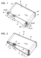
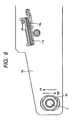
- FIG. 1 shows an outside appearance of the belt tensioning device 50 according to the present embodiment.
- the belt tensioning device 50 is tensioned by the belt member 1 and three rollers: a drive roller 2 for driving the belt member 1; a driven roller (platen roller) 3 for driven-rotating; and a tension roller 4, as a plurality of tensioning members for tensioning the belt member 1.
- first and second side plates 9a, 9b hold the bearings 6, 7 and 8 for supporting three rollers.
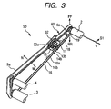
- FIG. 2 shows a state in which by removing one side plate (first side plate) 9a from the belt tensioning device 50, the interior has been arranged so that it can be seen
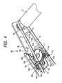
- FIG. 3 shows a cut model of the belt tensioning device 50, showing a look in which parts held by the first side plate 9a are seen from the inside of the first side plate 9a (Of the belt member 1, the belt surface is omitted).
- the drive roller 2 is driven by a power source (not shown) provided in the main body A of the image forming apparatus to rotate.
- the belt member 1 rotationally moves (moves in a cycle) in such a manner that the belt member 1 circulates around the drive roller 2, the driven roller 3 and the tension roller 4 in a direction indicated by an arrow Bf in the figure.
- the bearing 6a on the movable side of the drive roller 2, that is, on the first side plate 9a side is held by a long and narrow bearing holding hole 9a1 provided in the first side plate 9a so as to be slidable in a direction indicated by an arrow FF/RR in the figure.
- the bearing 6b of the drive roller 2 on the second side plate 9b side is fixed at a bearing holding hole 9b1 provided in the second side plate 9b.
- the drive roller 2 is adapted to be rockable in a direction indicated by an arrow S1 in FIG. 3 with the bearing 6b on the second side plate 9b side as a center of rocking.
- the bearings 7a, 7b for axially supporting the driven roller 3 are fixed by bearing holding holes 9a2, 9b2 provided in the first and second side plates respectively.
- the driven roller 3 driven-rotates by moving the belt member 1 by the drive roller 2.
- the tension roller 4 is movably held in a direction indicated by an arrow T in the figure, that is, in a direction to separate from a plane which is formed by the belt member 1 extended between the drive roller 2 and the driven roller 3.
- the bearings 8a, 8b for axially supporting the tension roller 4 are slidably held by long and narrow bearing holding holes 9a3, 9b3 provided in the first and second side plates 9a, 9b respectively, and these bearings 8a, 8b are biased by a tension roller biasing spring 5, which is an elastic member, as biasing means.
- the belt member 1 is, in the present embodiment, an endless belt formed by polyimide, having circumference of 675 mm, width of 258 mm and thickness of 60 ⁇ m.
- the material of the intermediate transferring member is not limited thereto, but in addition to the above-described one, a belt member 1 formed by polycarbonate, PVDF, ETFE, PTFE and the like can be suitably used.
- the belt member 1 has a rib 16 (rib member), which is a convex portion of the belt member 1, mounted in the neighborhood of one edge portion (first side plate 9a side) 1a in a substantially orthogonal direction (lateral direction (shift direction) of the belt member 1) to the conveying direction (direction of movement of rotation) Bf on the inner part thereof.
- the rib 16 stands up in a substantially orthogonal direction to the belt surface, extending over the entire circumference of the belt member 1. This is a projection formed by urethane having width of 4 mm and height of 1.5 mm, and is provided 0.5 mm inside from an edge portion 1a of the belt member 1 on the first side plate 9a side.
- a center adjusting mechanism (center adjusting unit) 60 which the belt tensioning device 50 has.
- the belt tensioning device 50 has such a center adjusting unit 60 of the belt member 1 as explained below.
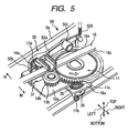
- FIGS. 4 and 5 show an enlarged center adjusting unit 60 (of the belt member 1, the belt surface is omitted).
- the belt tensioning device 50 has: the belt member 1 for transferring a toner image on the photosensitive drum 111 onto the transferring material P; a first tensioning member (driven roller 3 or tension roller 4) for tensioning the belt member 1; and a second tensioning member (drive roller 2) capable of tensioning the belt member 1 and changing an angle with respect to the first tensioning member.
- the belt tensioning device 50 has contact members 13a, 13b which are drive receiving means constructed such that they can come into contact with the belt member 1 and a contact state with the belt member 1 changes, and in response to a contact state between these contact members 13a, 13b and the belt member 1, an angle of the second tensioning member (drive roller 2) to the first tensioning member (driven roller 3 or tension roller 4) is adapted to change.
- the belt member 1 moves in a direction indicated by an arrow N/M in the figure, that is, in a direction substantially orthogonal to the conveying direction Bf of the belt member 1.
- the contact members 13a, 13b are constructed so as to be able to receive a driving force of the belt member 1 by coming into contact with the belt member 1 in such a manner that the driving force to be inputted from this belt member 1 changes an angle of the drive roller 2 to the driven roller 3 or the tension roller 4.
- an amount of the driving force of the belt member 1 to be inputted to the contact members 13a, 13b is caused to differ; depending on a position of the belt member 1 in a direction substantially orthogonal to the conveying direction of the belt member 1, there will be caused to be a case where the driving force is inputted to the first or second contact member 13a, 13b and a case where no driving force is inputted; and depending on the driving force to be inputted into the first contact member 13a or the second contact member 13b, the angles of the drive roller 2 to the driven roller 3 and the tension roller 4 will be caused to change in the opposite direction to each other.
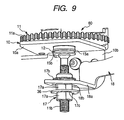
- the center adjusting unit 60 has: freely rotatable first and second rollers 13a, 13b which are first and second contact members provided so as to be able to come into contact with, in the neighborhood of an end portion in a direction substantially orthogonal to the conveying direction Bf of the belt member 1, in this case, side surfaces 16a, 16b respectively to which the rib 16, which is the drive input portion provided on the belt member 1, opposes; a gear portion 11a of a threaded gear 11 as a freely rotatable rotation member to which turning effects of the first and second rollers 13a, 13b are transmitted; a threaded portion (spiral boss) 11b of the threaded gear 11 as driving means coaxial to the gear portion 11a, for rotating integrally; a nut 17, which is a moving element which engages with the threaded portion 11b and is driven by rotation of the threaded portion 11b; and a lever 18, which is a coupling element for transmitting to a movable portion of a drive roller 2 in
- the center adjusting unit 60 has a center adjusting unit chassis 10 fixed to the first side plate 9a.
- the center adjusting unit chassis 10 has the main body 10a of a chassis substantially parallel with the surface of the belt member 1 tensioned between the drive roller 2 and the tension roller 4 and a chassis installation area 10b for extending in a direction substantially orthogonal to the main body 10a of the chassis, and the chassis installation area 10b is fixed along the first side plate 9a, whereby the center adjusting unit chassis 10 is arranged at a predetermined position.
- the rollers 13a, 13b, the threaded gear 11 and the like are installed to this center adjusting unit chassis 10.
- the threaded gear 11 is installed to the main body 10a of the center adjusting unit chassis 10 such that it does not move in the longitudinal direction (vertical direction) of the threaded portion 11b, but becomes freely rotatable.
- the threaded gear 11 is supported such that a sliding portion 11c for constituting a rotating shaft in the neighborhood of a coupled portion between the gear portion 11a and the threaded portion 11b can be rotated by a bearing portion 10c provided on the main body 10a of the center adjusting unit chassis 10.
- a fastening member 12 is fixed, whereby this fastening member 12 bumps against a washer 15a which has been inserted through the threaded portion 11b and arranged below the bearing portion 10c in such a manner that the threaded gear 11 does not move in the longitudinal direction of the threaded portion 11b.
- the first, and second rollers 13a, 13b are, in the present embodiment, friction member rings at the outer periphery of which an elastic friction member has been provided.
- an elastic friction member EPDM has been used, chloroprene rubber, urethane rubber, urethane foam and the like can be suitably used in addition.
- first and second small gears 14a, 14b are fixed ( Fig.5 ).
- the first and second rollers 13a, 13b are rotatively installed on the main body 10a of the center adjusting unit chassis 10 with a predetermined clearance to the rib 16 of the belt member 1 respectively, and in such a manner that the first and second small gears 14a, 14b engage with the gear portion 11a of the threaded gear 11.
- the nut 17 is threadedly engaged with the threaded portion 11b of the threaded gear 11, and is held so as not to rotate in the direction of rotation of the threaded portion 11b.
- a rectangular sliding hole 18b provided in a drive receiving portion 18a of the lever 18 is caused to pass along a side surface 17a substantially uniformly flat to which the nut 17 opposes.
- a biasing spring 35 which is an elastic member, as biasing means around the threaded portion 11b of the threaded gear 11.
- the biasing spring 35 biases the nut 17 in a direction of the central position so as to threadedly engage with the threaded portion 11b again.
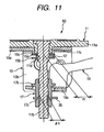
- the lever 18 holds the nut 17 by the drive receiving portion 18a provided at one end portion in the longitudinal direction thereof as described above, and receives the movement of the nut 17 in a direction indicated by an arrow U/D in figure 7 to transmit this movement to the movable portion of the drive roller 2, that is, the bearing 6a on the first side plate 9a side.
- a shaft hole 18d is fitted in a rotary center axis 19 provided on the first side plate 9a, and the lever 18 is pivotally held by the first side plate 9a with the rotary center 19 axis as the center.
- an end portion 18c on the opposite side to the drive receiving portion 18a of the lever 18 is fixed to the bearing 6a of the drive roller 2 on the first side plate 9a side ( Fig.8 ).
- the center adjusting unit 60 is provided with rib guide means 30 for guiding so as to hold the rib 16 within such a range as to be able to input a driving force to the first and second rollers 13a, 13b.
- the rib guide means 30 has a guide 31 and a guide lever 32 for sandwiching the rib 16 from the lower side and the upper side respectively to prevent the rib 16 from deviating in the up-and-down direction from between the first and second rollers 13a, 13b ( Fig.5 ).
- the guide lever 32 is supported by the first side plate 9a so as to be able to rock in a direction indicated by an arrow S3 in figure 7 with the rocking center axis 32c as the center.
- the guide lever 32 is, at one end portion in the longitudinal direction, biased by a spring 32d which is an elastic member, as biasing means.
- the guide lever 32 sandwiches the rib 16 (and the belt member 11) between a sandwiching portion 32a provided in the neighborhood of the other end portion in the longitudinal direction and the guide 31.
- the guide lever 32 has a stopper 32b at the end portion on the sandwiching portion 32a side, and in order to hold the clearance with the guide 31 so that the belt member 11 is not pushed excessively by the guide lever 32, the leading edge of this stopper 32b is caused to bump against the main body 10a of the center adjusting unit chassis 10.
- the belt member 1 is driven by the drive roller 2 to rotate in a direction indicated by an arrow Bf. At this time, no matter how accurately the precision and parallelism of the drive roller 2, the driven roller 3, the tension roller 4 and the belt member 1 may be controlled, the belt member 1 has a tendency to shift along either of the directions indicated by an arrow N/M as a lateral direction (shift direction).
- the movement of the rib 16 has been regulated by a flange (not shown) provided as a regulating member, in such a manner that the movement of the belt member 1 in a direction substantially orthogonal to the conveying direction Bf of the belt member 1 is stopped.
- a flange not shown
- the rib 16 is shaved, the frictional force with the flange become higher to run on to the flange, and it becomes impossible to maintain a position of the belt member 1 at a predetermined position, resulting in damage to the rib 16 and the belt member 1.
- the nut 17 is caused to move in the direction (upward) indicated by the arrow U in the figure
- the lever 18 rotates in the direction indicated by the arrow X3 in the figure
- the bearing 6a of the drive roller 2 on the first side plate 9a side is caused to move in the direction (downward) indicated by the arrow X4 in the figure.
- the above-described operation controls the rib 16 so as to be always located between the first and second rollers 13a, 13b, and the belt member 1 is also held in such a position as to cause the rib 16 to exist within that range. Since the first and second rollers 13a, 13b for operating for belt training of the belt member 1 are arranged on both sides of the rib 16, a force for correcting an inclination to both directions can be obtained at a single end of the belt member 1.
- FIGS. 8 and 9 show an enlarged view obtained by observing surroundings of the threaded gear 11 from another angle.
- the center adjusting unit 60' is constructed as described below. In other words, in this case, the following parameter groups will be set as described below.
- friction moment caused by the thrust F is expressed by the following formula (2).
- material of the threaded portion of the threaded gear 11, material of the nut 17, material of a bearing for regulating movement of the threaded gear 11 and the threaded portion 11b of the threaded gear 11 in the longitudinal direction, an outer diameter ⁇ s of the threaded portion 11b, distance between the bearing of the threaded gear 11 and the center of the threaded portion 11b of a sliding portion rs, pitch Ps of the threaded portion 11b and the like can be appropriately set.
- a pitch of the threaded portion 11b of the threaded gear 11 needs not be constant, but in accordance with a response of inclination speed of the belt member 1, the pitch of the threaded portion 11b is made coarse, for embodiment, at the central part of the threaded portion 11b in the longitudinal direction, and fine on both end portion sides, that is, in the neighborhood of the side end portion of the coupled portion with the gear portion 11a and the leading edge, whereby a transfer function of the response is adjusted and time required to converge the belt training can be shortened.
- the thread on the nut 17 side is made into one turn or less.
- the precision/parallelism of the roller which is the belt tensioning member
- the precision of the belt member 1 and /or the rib 16 need not be strictly controlled, but distortion of the equipment during installation and the inclination tendency due to endurance use are automatically corrected in real time, whereby it is possible to hold the belt member 1 and/or the rib 16 at the predetermined position without applying a continuous stress on them, and to avoid any damage due to the belt member 1 and/or the rib running on the regulating member.
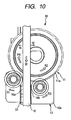
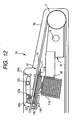
- FIG. 12 is a side view in which the first side plate 9a of the belt tensioning device 50 has been seen from the inside, showing the feature of the center adjusting unit 62 of the belt tensioning device 51 according to the present embodiment exceedingly well.
- the drive receiving portion 18a of the lever 18 and the nut 17 have been engaged with each other with a clearance (direction indicated by an arrow Q1, Q2 in figure 7 .
- the moving element (nut 17) which is driven, for moving, by driving means (threaded portion 11b of the threaded gear 11) which is rotated by turning effect of the first and second rollers 13a, 13b, which are contact members, has been handled as a separate member from the drive receiving portion 18a of the lever 18.
- these driving means and moving means are made integral.
- a worm gear consisting of a worm (spiral boss) 11d which rotates integrally with the gear portion 11a of the threaded gear 11 as a rotation member, and a partial worm wheel 18f provided at the leading edge of the lever 18, which is a coupling element, the lever 18 is driven.
- the worm wheel 18f, which is the moving element, and the drive receiving portion of the lever 18 are made integral.
- the similar effect to the first embodiment can be exhibited, the number of parts is reduced, and the clearance is reduced, and therefore, the responsivity of the belt training operation is improved.
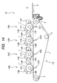
- FIG. 14 shows schematic cross-sectional structure of one embodiment of the image forming apparatus of such a type.
- the image forming apparatus 101 has each image forming unit 110Y, 110M, 110C and 110K for forming toner images of each color of yellow, magenta, cyan and black respectively as a plurality of image forming means. Since in each image forming unit, a process of forming toner images on photosensitive drums 111Y, 111M, 111C and 111K, which are image bearing members is similar to one explained in the first embodiment, elements having functions and structure identical to or corresponding to the image forming apparatus 100 of the first embodiment are designated by the identical reference numerals, and detailed description is omitted.
- transferring material P is sent out from a transferring material supply unit (not shown) to be supplied onto the belt member 1, which is the transferring material bearing member.
- a transferring material supply unit (not shown) to be supplied onto the belt member 1, which is the transferring material bearing member.
- toner images of each color formed on each photosensitive drum 111Y, 111M, 111C and 111K are transferred in order on the transferring material P to be conveyed on the belt member 1 by the operation of transferring means 115Y, 115M, 115C and 115K arranged in opposition to each photosensitive drums 111Y, 111M, 111C and 111K via the belt member 1.
- the transferring material P is separated from the belt member 1 to be conveyed to a fixing device which is fixing means (not shown), where an unfixed toner image is fixed and thereafter, is discharged outside the image forming apparatus.
- the present invention can be also suitably applied to an image forming apparatus equipped with the belt member 1 which is used as such a transferring material bearing member.
- the transferring material conveying unit 170 (may be either detachably attachable to the main body A of the image forming apparatus or fixed) is caused to have the same structure as the belt tensioning device 50 or 51 having the center adjusting unit 60 explained in each of the above-described embodiments, whereby the operation effect similar to each of the above-described embodiments can be exhibited.
- the printer has been illustrated as the image forming apparatus, but the present invention is not limited thereto, but other image forming apparatuses such as, for embodiment, copying machines and facsimiles or other image forming apparatuses such as compound machines obtained by combining these functions may be used, and the similar effect can be obtained by applying the present invention to the image forming apparatuses.
- image forming apparatuses such as, for embodiment, copying machines and facsimiles or other image forming apparatuses such as compound machines obtained by combining these functions may be used, and the similar effect can be obtained by applying the present invention to the image forming apparatuses.
- the belt member may be tensioned using four or more tensioning rollers.
Landscapes
- Physics & Mathematics (AREA)
- General Physics & Mathematics (AREA)
- Electrostatic Charge, Transfer And Separation In Electrography (AREA)
- Electrophotography Configuration And Component (AREA)
Claims (13)
- Bilderzeugungsvorrichtung, die Folgendes aufweist:ein Bandbauteil (1), das eine Drehbewegung bewirkt;ein erstes Spannbauteil (4) zum Spannen des Bandbauteils (1);ein zweites Spannbauteil (2) zum Spannen des Bandbauteils (1), wobei ein Winkel des zweiten Spannbauteils (2) relativ zu dem ersten Spannbauteil (4) angepasst ist, um sich zu ändern;ein elastisches Bauteil (5) zum Vorspannen des ersten Spannbauteils (4); undeine Antriebsaufnahmeeinrichtung (13a, 13b) zum Aufnehmen einer Kraft durch die Drehbewegung des Bandbauteils (1), wobei der Winkel in Abhängigkeit von der Kraft, die durch die Antriebsaufnahmeeinrichtung (13a, 13b) aufgenommen ist, geändert ist,dadurch gekennzeichnet, dass
das Bandbauteil (1) einen konvexen Abschnitt (16) aufweist, der im Wesentlichen orthogonal von einer Bandbauteilfläche vorragt;
die Antriebsaufnahmeeinrichtungen (13a, 13b) angepasst sind, um die Kraft durch die Drehbewegung des Bandbauteils (1) durch ein Berühren des konvexen Abschnitts (16) aufzunehmen. - Bilderzeugungsvorrichtung nach Anspruch 1, wobei das erste Spannbauteil (4) und das zweite Spannbauteil (2) eine Walzenform aufweisen und ein Winkel des zweiten Spannbauteils (2) zu dem ersten Spannbauteil (4) ein Winkel zwischen einer Mittelachse des zweiten Spannbauteils (2) und einer Mittelachse des ersten Spannbauteils (4) ist.
- Bilderzeugungsvorrichtung nach Anspruch 1, wobei das Bandbauteil (1) gestaltet ist, um ein Tonerbild zu tragen.
- Bilderzeugungsvorrichtung nach Anspruch 1, wobei das Bandbauteil (1) gestaltet ist, um ein Übertragungsmaterial zu tragen.
- Bilderzeugungsvorrichtung nach Anspruch 1, wobei ein Eingabebetrag der Kraft durch eine Bewegung zu der Antriebsaufnahmeeinrichtung (13a, 13b) variiert, wenn eine Position des Bandbauteils (1) in einer lateralen Richtung variiert.
- Bilderzeugungsvorrichtung nach Anspruch 1, wobei es Fälle gibt, in denen eine Kraft durch eine Bewegung eingegeben ist und nicht eingegeben ist, entsprechend einer Position des Bandbauteils (1) in einer lateralen Richtung des Bandbauteils (1).
- Bilderzeugungsvorrichtung nach Anspruch 1, wobei die Antriebsaufnahmeeinrichtung (13a, 13b) ein erstes Antriebsbauteil (13a) und ein zweites Antriebsbauteil (13b) aufweist, in die jeweils eine Kraft durch eine Bewegung eingegeben ist,
wobei Arten eines Änderns eines Winkels des zweiten Spannbauteils (2) zu dem ersten Spannbauteil (4) in jedem von den Fällen verschieden sind, in denen die Kraft durch eine Bewegung an das erste Antriebsbauteil (13a) eingegeben ist und die Kraft durch eine Bewegung an das zweite Antriebsbauteil (13b) eingegeben ist. - Bilderzeugungsvorrichtung nach Anspruch 1, wobei der konvexe Abschnitt (16) durch ein Rippenbauteil gebildet ist.
- Bilderzeugungsvorrichtung nach Anspruch 1, wobei die Antriebsaufnahmeeinrichtung (13a, 13b) ein erstes Antriebsbauteil (13a) und ein zweites Antriebsbauteil (13b) aufweist, in die jeweils eine Kraft durch eine Bewegung eingegeben ist, und das erste Antriebsaufnahmebauteil (13a) und das zweite Antriebsaufnahmebauteil (13b) gestaltet sind, um den konvexen Abschnitt (16) an beiden Seiten des konvexen Abschnitts (16) in einer lateralen Richtung des Bandbauteils (1) zu berühren.
- Bilderzeugungsvorrichtung nach einem der Ansprüche 1 bis 8, mit einer Antriebsumwandlungseinrichtung zum Umwandeln der Kraft, die durch die Antriebsaufnahmeeinrichtung (13a, 13b) aufgenommen ist, in eine Kraft, um einen Winkel des zweiten Spannbauteils (2) relativ zu dem ersten Spannbauteil (4) zu ändern, wobei die Antriebsumwandlungseinrichtung gestaltet ist, um zu verhindern, dass eine Kraft von dem zweiten Spannbauteil (2) an die Antriebsaufnahmeeinrichtung (13a, 13b) übertragen ist.
- Bilderzeugungsvorrichtung nach Anspruch 10, wobei die Antriebsumwandlungseinrichtung gestaltet ist, um eine Kraft durch eine Drehbewegung in eine Kraft entlang einer Richtung einer Drehachse der Kraft durch die Drehbewegung umzuwandeln.
- Bilderzeugungsvorrichtung nach Anspruch 10, wobei die Antriebsumwandlungseinrichtung einen Gewindeabschnitt (11b) und ein nutförmiges Bauteil (17) aufweist.
- Bilderzeugungsvorrichtung nach Anspruch 10, wobei die Antriebsumwandlungseinrichtung ein schneckenradförmiges Bauteil (18f) und ein schneckenförmiges Bauteil (11d) aufweist.
Applications Claiming Priority (2)
| Application Number | Priority Date | Filing Date | Title |
|---|---|---|---|
| JP2003329180A JP4366162B2 (ja) | 2003-09-19 | 2003-09-19 | 画像形成装置 |
| JP2003329180 | 2003-09-19 |
Publications (2)
| Publication Number | Publication Date |
|---|---|
| EP1517190A1 EP1517190A1 (de) | 2005-03-23 |
| EP1517190B1 true EP1517190B1 (de) | 2012-03-21 |
Family
ID=34191414
Family Applications (1)
| Application Number | Title | Priority Date | Filing Date |
|---|---|---|---|
| EP04022068A Expired - Lifetime EP1517190B1 (de) | 2003-09-19 | 2004-09-16 | Bildformungsapparatus mit Meanderkorrektur eines Bandes |
Country Status (4)
| Country | Link |
|---|---|
| US (3) | US7239828B2 (de) |
| EP (1) | EP1517190B1 (de) |
| JP (1) | JP4366162B2 (de) |
| CN (1) | CN100504632C (de) |
Families Citing this family (19)
| Publication number | Priority date | Publication date | Assignee | Title |
|---|---|---|---|---|
| JP4366162B2 (ja) * | 2003-09-19 | 2009-11-18 | キヤノン株式会社 | 画像形成装置 |
| KR100618326B1 (ko) * | 2004-08-31 | 2006-08-31 | 삼성전자주식회사 | 벨트 클러치 장치 및 이를 구비한 화상형성장치 |
| US7430393B2 (en) * | 2006-07-03 | 2008-09-30 | Canon Kabushiki Kaisha | Belt feeding device and image heating device |
| US8095053B2 (en) | 2007-04-17 | 2012-01-10 | Kabushiki Kaisha Toshiba | Transfer belt unit for image forming apparatus including a steering roller to correct meandering |
| JP4324621B2 (ja) * | 2007-04-17 | 2009-09-02 | シャープ株式会社 | 中間転写ユニット着脱機構及び中間転写ユニット着脱方法 |
| JP5078503B2 (ja) * | 2007-08-22 | 2012-11-21 | キヤノン株式会社 | ベルト搬送装置及び画像形成装置 |
| JP5063273B2 (ja) * | 2007-09-21 | 2012-10-31 | キヤノン株式会社 | ベルト搬送装置及び画像形成装置 |
| US7873311B2 (en) * | 2007-12-05 | 2011-01-18 | Kabushiki Kaisha Toshiba | Belt transfer device for image forming apparatus |
| CN101934649A (zh) * | 2008-04-16 | 2011-01-05 | 株式会社东芝 | 带装置及带的自转向方法 |
| CN101279550B (zh) * | 2008-04-16 | 2010-11-10 | 株式会社东芝 | 转印带装置及转印带的自转向方法 |
| US20110070001A1 (en) * | 2009-09-22 | 2011-03-24 | Kabushiki Kaisha Toshiba | Steering Mechanism for Belt Unit |
| JP2013076863A (ja) | 2011-09-30 | 2013-04-25 | Canon Inc | ベルト搬送装置及び画像形成装置 |
| JP5870784B2 (ja) * | 2012-03-16 | 2016-03-01 | カシオ電子工業株式会社 | ベルト片寄り矯正機構及びそれを備えた画像形成装置 |
| JP6112781B2 (ja) | 2012-06-01 | 2017-04-12 | キヤノン株式会社 | 画像形成装置 |
| TW201350352A (zh) * | 2012-06-04 | 2013-12-16 | Hon Hai Prec Ind Co Ltd | 印表機的傳動帶張力調節裝置 |
| JP6164522B2 (ja) * | 2012-12-27 | 2017-07-19 | 株式会社リコー | ベルト装置、及び、画像形成装置 |
| JP6422290B2 (ja) * | 2014-10-02 | 2018-11-14 | キヤノン株式会社 | 画像形成装置 |
| CN111589214B (zh) * | 2020-05-14 | 2022-04-29 | 郑州沃特节能科技股份有限公司 | 一种用于钢渣处理的过滤网带装置 |
| CN113040571B (zh) * | 2021-04-15 | 2022-05-03 | 吾将文化科技集团有限公司 | 一种基于液压的互动展台 |
Family Cites Families (37)
| Publication number | Priority date | Publication date | Assignee | Title |
|---|---|---|---|---|
| JPS5760347A (en) * | 1980-09-29 | 1982-04-12 | Toshiba Corp | Snake motion preventing apparatus for belt |
| US4429985A (en) | 1981-02-20 | 1984-02-07 | Ricoh Company, Ltd. | Recording system provided with a device for correcting deviation of recording member in endless belt form |
| JPS57200050A (en) | 1981-06-04 | 1982-12-08 | Ricoh Co Ltd | Self-correcting device for endless belt meandering |
| US4397538A (en) * | 1981-09-03 | 1983-08-09 | Xerox Corporation | Belt alignment system |
| DE3332143C2 (de) * | 1982-09-06 | 1986-07-17 | Ricoh Co., Ltd., Tokio/Tokyo | Elektrophotographisches Aufzeichnungsgerät mit einem endlosen photoleitenden Band als Aufzeichnungsträger |
| JPS6057043A (ja) | 1983-09-09 | 1985-04-02 | Ricoh Co Ltd | ベルト緊張ロ−ラの後退機構 |
| US5017969A (en) * | 1988-05-30 | 1991-05-21 | Canon Kabushiki Kaisha | Device having movable belt |
| DE69121466T2 (de) * | 1990-05-24 | 1997-03-27 | Bando Chemical Ind | Bandantriebssystem |
| JPH0699055B2 (ja) | 1990-05-24 | 1994-12-07 | バンドー化学株式会社 | ベルト駆動装置 |
| JPH0460916A (ja) | 1990-06-26 | 1992-02-26 | Kubota Corp | 金属薄膜型磁気記録媒体 |
| JPH0514046A (ja) | 1991-07-05 | 1993-01-22 | Mitsubishi Electric Corp | フエーズドアレーアンテナ |
| JP2788683B2 (ja) | 1991-09-17 | 1998-08-20 | シャープ株式会社 | ベルトの蛇行制御装置 |
| JPH05324074A (ja) * | 1992-05-21 | 1993-12-07 | Nec Niigata Ltd | 電子写真式プリンタのベルト位置補正装置 |
| JP3209451B2 (ja) | 1992-06-23 | 2001-09-17 | キヤノン株式会社 | 画像形成装置 |
| US5246099A (en) * | 1992-09-23 | 1993-09-21 | Xerox Corporation | Belt steering roller mechanism and steering roll construction |
| JPH06255826A (ja) | 1993-03-09 | 1994-09-13 | Toshiba Corp | 画像形成装置 |
| US5410389A (en) * | 1993-08-30 | 1995-04-25 | Xerox Corporation | Neutral side force belt support system |
| US5717984A (en) * | 1996-01-11 | 1998-02-10 | Xerox Corporation | Driving, steering and tensioning roll for belt loops |
| JPH10231041A (ja) | 1997-02-19 | 1998-09-02 | Fuji Xerox Co Ltd | ベルト蛇行制御装置および画像形成装置 |
| JPH11106081A (ja) | 1997-10-01 | 1999-04-20 | Ricoh Co Ltd | 電子写真装置の感光ベルト寄止め機構 |
| KR100584533B1 (ko) * | 1998-07-21 | 2006-05-30 | 삼성전자주식회사 | 인쇄기용 감광벨트 조정장치 |
| JP2000075697A (ja) | 1998-08-28 | 2000-03-14 | Bando Chem Ind Ltd | ベルト定着装置 |
| JP2000075700A (ja) | 1998-08-28 | 2000-03-14 | Bando Chem Ind Ltd | ベルト定着装置 |
| JP2000072218A (ja) | 1998-08-28 | 2000-03-07 | Bando Chem Ind Ltd | ベルト駆動装置 |
| JP2000075699A (ja) | 1998-08-28 | 2000-03-14 | Bando Chem Ind Ltd | ベルト定着装置 |
| JP2000075698A (ja) | 1998-08-28 | 2000-03-14 | Bando Chem Ind Ltd | ベルト定着装置 |
| JP2000075708A (ja) | 1998-08-28 | 2000-03-14 | Bando Chem Ind Ltd | ベルト定着装置 |
| JP4207269B2 (ja) * | 1998-10-23 | 2009-01-14 | リコープリンティングシステムズ株式会社 | ベルト駆動装置 |
| JP2000199550A (ja) | 1999-01-05 | 2000-07-18 | Ricoh Co Ltd | ベルト駆動装置及びベルト定着装置及び画像形成装置 |
| US6134406A (en) * | 1999-03-11 | 2000-10-17 | Minnesota Mining And Manufacturing Company | Belt steering mechanism for use with an electrophotographic imaging system |
| JP2000272772A (ja) | 1999-03-25 | 2000-10-03 | Bando Chem Ind Ltd | ベルト駆動装置 |
| JP2000044083A (ja) | 1999-06-22 | 2000-02-15 | Canon Inc | 画像形成装置 |
| US6453143B2 (en) * | 2000-05-26 | 2002-09-17 | Canon Kabushiki Kaisha | Endless belt, method for manufacturing the endless belt, conveying device, tubular film, method for manufacturing the tubular film, and image forming apparatus |
| JP4555458B2 (ja) | 2000-12-11 | 2010-09-29 | カシオ計算機株式会社 | ベルト駆動装置及びそれを備えた電子写真装置 |
| JP2003246483A (ja) * | 2002-02-22 | 2003-09-02 | Canon Inc | テンション付与機構、及びこれを備えた画像形成装置 |
| US6594460B1 (en) * | 2002-09-10 | 2003-07-15 | Xerox Corporation | Low force lateral photoreceptor or intermediate transfer belt tracking correction system |
| JP4366162B2 (ja) * | 2003-09-19 | 2009-11-18 | キヤノン株式会社 | 画像形成装置 |
-
2003
- 2003-09-19 JP JP2003329180A patent/JP4366162B2/ja not_active Expired - Fee Related
-
2004
- 2004-09-16 EP EP04022068A patent/EP1517190B1/de not_active Expired - Lifetime
- 2004-09-17 US US10/943,030 patent/US7239828B2/en not_active Expired - Lifetime
- 2004-09-17 CN CNB2004100782202A patent/CN100504632C/zh not_active Expired - Fee Related
-
2007
- 2007-06-01 US US11/756,994 patent/US7379690B2/en not_active Expired - Fee Related
- 2007-06-01 US US11/756,982 patent/US7389068B2/en not_active Expired - Lifetime
Also Published As
| Publication number | Publication date |
|---|---|
| JP4366162B2 (ja) | 2009-11-18 |
| US20070225095A1 (en) | 2007-09-27 |
| EP1517190A1 (de) | 2005-03-23 |
| CN1598705A (zh) | 2005-03-23 |
| JP2005092153A (ja) | 2005-04-07 |
| CN100504632C (zh) | 2009-06-24 |
| US7379690B2 (en) | 2008-05-27 |
| US7389068B2 (en) | 2008-06-17 |
| US20050063732A1 (en) | 2005-03-24 |
| US20070223967A1 (en) | 2007-09-27 |
| US7239828B2 (en) | 2007-07-03 |
Similar Documents
| Publication | Publication Date | Title |
|---|---|---|
| US7389068B2 (en) | Image forming apparatus with adjustment of belt member | |
| US7751762B2 (en) | Transfer device and image forming apparatus including the same | |
| US8577261B2 (en) | Belt device and image forming apparatus | |
| US10322893B2 (en) | Image forming apparatus | |
| US9042779B2 (en) | Transfer belt device and image forming apparatus including the same | |
| JP4000446B2 (ja) | 画像形成装置及びこれに用いられる作像ユニット | |
| US7877041B2 (en) | Image forming apparatus with exposure support member | |
| JP2002287527A (ja) | ベルト駆動装置及び画像形成装置 | |
| US8909101B2 (en) | Image forming apparatus with control of steering roller for adjusting position of belt member on which image is formed | |
| JP6019857B2 (ja) | ベルト搬送装置及び画像形成装置 | |
| EP1635230B1 (de) | Prozesskartusche mit vibrationsreduzierendem Element für das Getriebe und Bilderzeugungsgerät. | |
| JP4581580B2 (ja) | 画像形成装置及び画質調整方法 | |
| US20250011113A1 (en) | Belt conveyor device and image forming apparatus | |
| US20250011112A1 (en) | Belt conveyor device and image forming apparatus | |
| US20250011114A1 (en) | Belt conveyor device and image forming apparatus | |
| US20250011115A1 (en) | Belt conveyor device and image forming apparatus | |
| US9188930B2 (en) | Drive unit and image forming apparatus including same | |
| US5742887A (en) | Color image output apparatus for recording a color image having independently movable color image forming units | |
| JP2012128403A (ja) | 画像形成装置 | |
| JP4378132B2 (ja) | 画像形成装置 | |
| JP3638793B2 (ja) | 画像形成装置 | |
| US20250013173A1 (en) | Belt conveyor device and image forming apparatus | |
| US7917059B2 (en) | Developing device and image forming apparatus | |
| KR101123690B1 (ko) | 화상형성장치의 전사유닛 | |
| JP2005077774A (ja) | 画像形成装置 |
Legal Events
| Date | Code | Title | Description |
|---|---|---|---|
| PUAI | Public reference made under article 153(3) epc to a published international application that has entered the european phase |
Free format text: ORIGINAL CODE: 0009012 |
|
| AK | Designated contracting states |
Kind code of ref document: A1 Designated state(s): AT BE BG CH CY CZ DE DK EE ES FI FR GB GR HU IE IT LI LU MC NL PL PT RO SE SI SK TR |
|
| AX | Request for extension of the european patent |
Extension state: AL HR LT LV MK |
|
| 17P | Request for examination filed |
Effective date: 20050808 |
|
| AKX | Designation fees paid |
Designated state(s): DE FR IT |
|
| 17Q | First examination report despatched |
Effective date: 20061214 |
|
| GRAP | Despatch of communication of intention to grant a patent |
Free format text: ORIGINAL CODE: EPIDOSNIGR1 |
|
| GRAS | Grant fee paid |
Free format text: ORIGINAL CODE: EPIDOSNIGR3 |
|
| GRAA | (expected) grant |
Free format text: ORIGINAL CODE: 0009210 |
|
| AK | Designated contracting states |
Kind code of ref document: B1 Designated state(s): DE FR IT |
|
| REG | Reference to a national code |
Ref country code: DE Ref legal event code: R096 Ref document number: 602004036967 Country of ref document: DE Effective date: 20120516 |
|
| PLBE | No opposition filed within time limit |
Free format text: ORIGINAL CODE: 0009261 |
|
| STAA | Information on the status of an ep patent application or granted ep patent |
Free format text: STATUS: NO OPPOSITION FILED WITHIN TIME LIMIT |
|
| 26N | No opposition filed |
Effective date: 20130102 |
|
| REG | Reference to a national code |
Ref country code: DE Ref legal event code: R097 Ref document number: 602004036967 Country of ref document: DE Effective date: 20130102 |
|
| PGFP | Annual fee paid to national office [announced via postgrant information from national office to epo] |
Ref country code: IT Payment date: 20140903 Year of fee payment: 11 |
|
| PGFP | Annual fee paid to national office [announced via postgrant information from national office to epo] |
Ref country code: FR Payment date: 20140924 Year of fee payment: 11 |
|
| PG25 | Lapsed in a contracting state [announced via postgrant information from national office to epo] |
Ref country code: IT Free format text: LAPSE BECAUSE OF NON-PAYMENT OF DUE FEES Effective date: 20150916 |
|
| REG | Reference to a national code |
Ref country code: FR Ref legal event code: ST Effective date: 20160531 |
|
| PG25 | Lapsed in a contracting state [announced via postgrant information from national office to epo] |
Ref country code: FR Free format text: LAPSE BECAUSE OF NON-PAYMENT OF DUE FEES Effective date: 20150930 |
|
| PGFP | Annual fee paid to national office [announced via postgrant information from national office to epo] |
Ref country code: DE Payment date: 20201127 Year of fee payment: 17 |
|
| REG | Reference to a national code |
Ref country code: DE Ref legal event code: R119 Ref document number: 602004036967 Country of ref document: DE |
|
| PG25 | Lapsed in a contracting state [announced via postgrant information from national office to epo] |
Ref country code: DE Free format text: LAPSE BECAUSE OF NON-PAYMENT OF DUE FEES Effective date: 20220401 |