EP1517167A2 - Composant optique utilisant un élement de transmission optique joignant un support métallique - Google Patents
Composant optique utilisant un élement de transmission optique joignant un support métallique Download PDFInfo
- Publication number
- EP1517167A2 EP1517167A2 EP04022091A EP04022091A EP1517167A2 EP 1517167 A2 EP1517167 A2 EP 1517167A2 EP 04022091 A EP04022091 A EP 04022091A EP 04022091 A EP04022091 A EP 04022091A EP 1517167 A2 EP1517167 A2 EP 1517167A2
- Authority
- EP
- European Patent Office
- Prior art keywords
- transmission element
- optical
- optical transmission
- metal holder
- joining material
- Prior art date
- Legal status (The legal status is an assumption and is not a legal conclusion. Google has not performed a legal analysis and makes no representation as to the accuracy of the status listed.)
- Granted
Links
Images



Classifications
-
- G—PHYSICS
- G02—OPTICS
- G02B—OPTICAL ELEMENTS, SYSTEMS OR APPARATUS
- G02B7/00—Mountings, adjusting means, or light-tight connections, for optical elements
- G02B7/02—Mountings, adjusting means, or light-tight connections, for optical elements for lenses
- G02B7/025—Mountings, adjusting means, or light-tight connections, for optical elements for lenses using glue
-
- G—PHYSICS
- G02—OPTICS
- G02B—OPTICAL ELEMENTS, SYSTEMS OR APPARATUS
- G02B7/00—Mountings, adjusting means, or light-tight connections, for optical elements
- G02B7/008—Mountings, adjusting means, or light-tight connections, for optical elements with means for compensating for changes in temperature or for controlling the temperature; thermal stabilisation
-
- G—PHYSICS
- G02—OPTICS
- G02B—OPTICAL ELEMENTS, SYSTEMS OR APPARATUS
- G02B7/00—Mountings, adjusting means, or light-tight connections, for optical elements
- G02B7/02—Mountings, adjusting means, or light-tight connections, for optical elements for lenses
- G02B7/028—Mountings, adjusting means, or light-tight connections, for optical elements for lenses with means for compensating for changes in temperature or for controlling the temperature; thermal stabilisation
Definitions
- This invention relates to optical components, in which circumferential walls of optical transmission elements such as lenses partially join metal holders via joining materials, and metal holders for holding optical transmission elements.
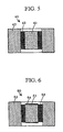
- FIG. 5 shows an example of the aforementioned optical device, which is disclosed in Japanese Patent Application Publication No. H02-281201.
- An optical device 40 shown in FIG. 5 is produced using an optical transmission element 41 made of an optical lens having a thermal expansion coefficient of 120 ⁇ 10 -7 /°C, which is arranged inside of a metal holder 42 made of a stainless steel having a thermal expansion coefficient of 170 ⁇ 10 -7 /°C and which then joins the metal holder 42 via a low melting point glass 43 composed of PbO-B 2 O 3 having a softening point of 350 °C and a thermal expansion coefficient of 110 ⁇ 10 -7 /°C.
- the optical device 40 comprising the optical transmission element 41 and the metal holder 42
- the adhesive generally has a high hygroscopic property, so that optical device 40 using the adhesive may become fragile in certain environmental conditions.
- the relatively low glass dislocation temperature reduces the use-allowable temperature range of the optical device 40 using the adhesive, and so-called "outgassing phenomenon" may occur. This causes a problem in that optical devices using the adhesive do not meet long-term reliability.
- the alloy solder composed of lead and tin has a relatively low melting point; therefore, when a certain load such as gravity is normally applied to the soldered portion of an optical device, a creeping phenomenon in which the solder becomes deformed over time may easily occur. That is, when the optical transmission element 41 and the metal holder 42 are fixed together using the alloy solder, the position of the optical transmission element 41 may vary over time; therefore, it is very difficult to guarantee the stability of the optical system over a long time.
- the alloy solder has a thermal expansion coefficient of 250 ⁇ 10 -7 /°C, which greatly differs from the thermal expansion coefficient of 120 ⁇ 10 -7 /°C of the optical transmission element 41.
- the optical transmission element 41 is fixed to the metal holder 42 via the alloy solder, a stress is applied to the optical transmission element 41 during the cooling of the alloy solder, which causes cracks and double refraction in the optical transmission element 41. Due to temperature variations or variations of surrounding temperature caused by heating of an electronic circuit and the like, tensile and compressive stresses may be repeatedly applied to the soldered portion. Furthermore, thermal fatigue may cause cracks in the solder so that the optical transmission element 41 may be varied in position and in optical axis. Because of the reasons described above, the optical device 40 is designed to use the low melting point glass 43.
- FIG. 6 shows an optical device 50 using an optical transmission element 51, which is improved in transmittance by forming an antireflection film 54 therewith.
- the optical device 50 of FIG. 6 is produced such that the optical transmission element 51 having the antireflection film 54 is arranged inside of the metal holder 52, and then it joins the metal holder 52 via a low melting point glass 53.
- the antireflection film 54 has a heat resistance of 400 °C or less.
- the PbO-B 2 O 3 material which is normally used for the low melting point glass 53, to have a reduced burning temperature of 450 °C or less; that is, it is difficult for the burning temperature of the low melting point glass 53 to be decreased to be equal to the heat resistance temperature of the antireflection film 54 or less.
- the low melting point glass 53 has a surface (or surfaces) exposed to the atmosphere other than surfaces thereof joining the optical transmission element 51 and the metal holder 52. This may accelerate the deterioration of the low melting point glass 53 in high humidity environments.
- another type of an optical device in which an optical transmission element joins a metal holder by using a low melting point glass whose lead content is 0.1 weight % or less is disclosed in Japanese Patent Application Publication No. 2003-40648. Due to the constitution of the optical device in which the optical transmission element joins the metal holder by using the low melting point glass whose lead content is 0.1 weight % or less, the burning temperature can be decreased to 400 °C or less; thus, it is possible to improve the reliability in securing desired optical transmission characteristics. Since the low melting point glass has a relatively low lead content that is 0,1 weight % or less, it is possible to produce the optical device that is environmentally friendly to the earth.
- the optical transmission element e.g., an optical lens
- the metal holder in the optical device or optical component
- the incoming light incident on the optical transmission element is varied in optical characteristics.
- it may be possible to avoid unwanted reduction of the optical characteristics of the optical transmission element by providing a bank keeping the low melting point glass in the metal holder, wherein it is possible to actualize the condition in which the low melting point glass is eliminated from the periphery of the optical transmission element when the optical transmission element joins the metal holder.
- the optical characteristics must be deteriorated.
- the optical transmission element joins the metal holder by using the joining material such as the low melting point glass
- the joining material such as the low melting point glass
- cracks and double refraction may occur in the optical transmission element due to the stress based on the difference between the thermal expansion coefficients of the prescribed parts, which raises a problem in that a light extinction ratio must be deteriorated.
- This problem may be solved by using the low melting point glass whose thermal expansion coefficient approximates the thermal expansion coefficient of the optical transmission element.
- due to tensile stress caused by the combination of materials cracks or separations may easily occur on the surface of the optical transmission element.
- An optical component of this invention is designed such that the circumferential wall of an optical transmission element partially joins a metal holder via a joining material, wherein a stress applied to the optical transmission element when joining the metal holder is normally directed in a compression direction of the optical transmission element, whereby it is possible to prevent cracks and separations from occurring in the optical transmission element. As a result, it is possible to prevent errors from occurring in optical characteristics, regardless of variations of the environmental temperature. Thus, it is possible to present the optical component having a high reliability.
- the above can be evaluated by using a thermal expansion coefficient ⁇ 1 of the optical transmission element, a thermal expansion coefficient ⁇ 2 of the joining material, and a thermal expansion coefficient ⁇ 3 of the metal holder. It is necessary to satisfy the relationship of ⁇ 1 ⁇ 2 ⁇ 3 by adequately selecting materials for the optical transmission element, joining material, and metal holder, whereby when the optical transmission element joins the metal holder, the stress applied to the optical transmission element can be normally directed in the compression direction of the optical transmission element. Thus, even when the circumferential wall of the optical transmission element partially joins the metal holder, it is possible to reliably prevent cracks and separations from occurring in the optical transmission element.
- prescribed materials should be preferably selected for the optical transmission element, joining material, and metal holder in such a way that a difference between the thermal expansion coefficients of the joining material and optical transmission element, i.e., ( ⁇ 2- ⁇ 1), ranges from 5 ⁇ 10 -7 /°C to 50 ⁇ 10 -7 /°C, and a difference between the thermal expansion coefficients of the metal holder and joining material, i.e., ( ⁇ 3- ⁇ 2), ranges from 5 ⁇ 10 -7 /°C to 100 ⁇ 10 -7 /°C.
- the thermal expansion coefficient ⁇ 1 of the optical transmission element ranges from 60 ⁇ 10 -7 /°C to 80 ⁇ 10 -7 /°C
- the thermal expansion coefficient ⁇ 2 of the joining material ranges from 70 ⁇ 10 -7 /°C to 90 ⁇ 10 -7 /°C
- the thermal expansion coefficient ⁇ 3 of the metal holder ranges from 80 ⁇ 10 -7 /°C to 100 ⁇ 10 -7 /°C.
- the optical transmission element joins the joining material at two positions or more, which are symmetric to the center axis of the optical transmission element, in order to secure a relatively high joining strength.
- the optical transmission element is inserted into a through hole that is formed to penetrate through the metal holder along the center axis, wherein a bank for keeping the joining material is actualized by a tapered portion, which is formed in proximity to one end of the through hole of the metal holder in relation to the optical transmission element, whereby it is possible to prevent the joining material from flowing into other portions other than the joining portion of the optical transmission element inserted into one end of the through hole of the metal holder. That is, the metal holder has the tapered portion serving as the bank, which is filled with a sufficient amount of the joining material. Thus, it is possible to produce the optical component that is superior in the joining strength with the metal holder and in the airtight property.
- this invention reliably prevents the joining material from flowing into other portions other than the joining portion of the optical transmission element inserted into one end of the through hole of the metal holder. This avoids the occurrence of abnormality in optical characteristics of the optical component; hence, it is possible to provide the optical component having a high reliability.
- the tapered portion is slanted in an insertion direction of the optical transmission element, which is inserted into the through hole of the metal holder, whereby the thickness of the joining material is reduced along the inclination of the tapered portion.
- This allows the 'melted' joining material, which is made wet, to flow along the tapered portion of the metal holder due to gravity, whereby it is possible to improve the joining property of the metal holder joining the optical transmission element; hence, it is possible to produce an optical component that is superior in joining strength and airtight characteristics.
- the optical transmission element is accompanied with an antireflection film (or AR coating)
- the optical transmission element be made of one of the optical glass, optical crystal, and ceramics.
- the optical crystal is preferably selected from among quartz crystal, rutile (titanium oxide), garnet, alumina (Al 2 O 3 ), lithium niobate (LiNbO 3 ), calcium fluoride (or fluorite) (CaF 2 ), lithium fluoride (LiF), magnesium fluoride (MgF 2 ), barium fluoride (BaF 2 ), thallium iodobromide (KRS-5), thallium bromochloride (KRS-6), sodium chloride (NaCl), potassium bromide (KBr), potassium chloride (KCl), cesium iodide (Csl), and zinc selenide (ZnSe), etc.
- the optical glass is preferably selected from among FK (fluorosilicate crown), PK (phosphate crown), ZK (zinc crown), BaK (barium crown), LaK (lanthanum crown), LF (light flint), SF (dense flint), LaF (lanthanum flint), and LsSF (dense lanthanum flint), etc.
- FK fluorosilicate crown
- PK phosphate crown
- ZK zinc crown
- BaK barium crown
- LaK lanthanum crown
- LF light flint
- SF dodet flint
- LaF laF
- LsSF dense lanthanum flint
- the shape of the optical transmission element can be adequately selected to suit the application thereof from among the cylindrical shape, spherical shape, planar shape, and prismatic shape, for example.
- an antireflection film whose material is selected from among SiO 2 , TiO 2 , ZrO 2 , and Ta 2 O 5 , etc. on the optical surface of the optical lens in consideration of the material and target reflection ratio of the optical lens.
- the determination as to the formation of the antireflection film on the optical lens can be made in consideration of the required optical characteristics and applications. That is, an antireflection film is formed on one side of the optical lens; antireflection films are formed on both sides of the optical lens; or no antireflection film is formed with respect to the optical lens.
- the organic adhesive is preferably selected from among polyimide adhesive, epoxy adhesive, UV (ultraviolet) adhesive, acrylic adhesive, and urethane adhesive, etc.
- the low melting point glass is mainly composed of SiO 2 or B 2 O 3 , which is preferably added with Al 2 O 3 , PbO, Na 2 O, K 2 O, BaO, Li 2 O, etc.
- the solder material it is preferable to selectively use the AuSn alloy solder, PbSn alloy solder, SnAgCu alloy solder, and the like. When the solder is used as the joining material, it is necessary to provide a metallized layer in the surrounding area of the optical component.
- the material for the metal holder is preferably selected from a Fe-Ni alloy and a Fe-Ni-Co alloy.
- the Fe-Ni alloy it is preferable to selectively use 58Fe42Ni (or 42 Alloy), 55Fe45Ni (or 45 Alloy), 52Fe48Ni (or 48 Alloy), 50Fe50Ni (or 50 Alloy), 48Fe52Ni (or 52 Alloy), 52Fe42Ni6Cr (or 426 Alloy), and 47Fe47Ni6Cr (or 476 Alloy).
- the Fe-Ni-Co alloy it is preferable to selectively use 54Fe29Ni17Co, 55Fe28Ni17Co, and 56Fe27Ni17Co.
- this invention is directed to an optical component in which the circumferential wall of an optical transmission element partially joins a metal holder via joining material, wherein stress is normally applied to the optical transmission element in its compression direction.
- FIGS. 1A and 1B diagrammatically show an optical component 10 in which an optical lens 11 joins a metal holder 12, wherein FIG. 1A is an upper view of the optical component 10; and FIG. 1B is a cross-sectional view showing the internal structure of the optical component 10 being cut at a plane vertically passing through the center of the illustration of FIG. 1A.
- FIGS. 2A and 2B show the manner in which the optical lens 11 joins the metal holder 12, wherein FIG. 2A is a cross-sectional view of the optical device 10 before the optical lens 11 completely joins the metal holder 12; and FIG. 2B is a cross-sectional view of the optical device 10 after the optical lens 11 completely joins the metal holder 12.
- the optical component 10 comprises the optical lens 11 roughly having a cylindrical shape, the metal holder (or a metal lens holder) 12 for fixing the optical lens 11 at a prescribed position, and a low melting point glass (i.e., a joining material) 13 that is melt to join the optical lens 11 and the metal holder 12 together.
- a low melting point glass i.e., a joining material
- the circumferential wall of the upper portion of the optical lens 11 partially joins the metal holder 12 via the low melting point glass 13.
- the optical lens 11 it is possible to provide two types of lenses denoted by reference symbols "a1" and "a2", wherein the optical lens a1 is composed of LaSF (i.e., dense lanthanum flint glass) whose thermal expansion coefficient is 65 ⁇ 10 -7 /°C, and the optical lens a2 is composed of SiO 2 +B 2 O 3 +Al 2 O 3 (i.e., boro-silicate glass) whose thermal expansion coefficient is 33 ⁇ 10 -7 /°C.
- Antireflection films 11a are formed on the light incoming plane and light outgoing plane of the optical lens 11.
- the material for the antireflection film 11a can be selected from among SiO 2 , TiO 2 , ZrO 2 , and Ta 2 O 5 in consideration of the material of the optical lens 11 and the 'target' reflection ratio. To meet the required characteristics and application, it is possible to adequately handle the antireflection film(s) 11a in such a way that the antireflection films 11a are formed on both of optical surfaces of the optical lens 11, the antireflection film 11a is formed on one of the optical surfaces of the optical lens 11, or no antireflection film is formed with respect to the optical lens 11.
- the metal lens holder 12 is formed in a cylindrical shape having a through hole penetrating the center thereof, wherein a chamfered portion 12a having a tapered portion 12b at one end thereof is formed. If there is a possibility that the metal lens holder 12 may be deteriorated due to corrosion, it is preferable that an antirust layer made of anticorrosion nickel plating is formed on the surface of the metal lens holder 12. In addition, it is preferable that the antirust layer made of nickel plating be peeled off from the prescribed portion of the metal lens holder 12 that joins the low melting point glass 13.
- b1 comprises a Fe-Ni-Co alloy (or a fernico alloy, i.e., 54Fe29Ni17Co) having a thermal expansion coefficient ( ⁇ 3) of 57 ⁇ 10 -7 /°C, which is composed of Fe at 54%, Ni at 29%, and Co at 17%
- b2 comprises a stainless steel (SUS316 defined in Japanese Industrial Standard, i.e., JIS) having a thermal expansion coefficient ( ⁇ 3) of 170 ⁇ 10 -7 /°C
- b3 comprises a stainless steel (SUS316L defined in JIS) having a thermal expansion coefficient ( ⁇ 3) of 175 ⁇ 10 -7 /°C
- b4 comprises a stainless steel (SUS304 defined in JIS) having a thermal expansion coefficient ( ⁇ 3) of 187 ⁇ 10 -7 /°C
- b5 comprises an alloy (i.e., 58Fe42Ni) having a thermal expansion coefficient
- b7 comprises an alloy (i.e., 54Fe46Ni) having a thermal expansion coefficient ( ⁇ 3) of 78 ⁇ 10 -7 /°C, which is composed of Fe at 54% and Ni at 46%;
- b8 comprises an alloy (i.e., 52Fe48Ni) having a thermal expansion coefficient ( ⁇ 3) of 88 ⁇ 10 -7 /°C, which is composed of Fe at 52% and Ni at 48%;
- b9 comprises an alloy (i.e., 50Fe50Ni) having a thermal expansion coefficient ( ⁇ 3) of 100 ⁇ 10 -7 /°C, which is composed of Fe at 50% and Ni at 50%;
- b10 comprises an alloy (i.e., 48Fe52Ni) having a thermal expansion coefficient ( ⁇ 3) of 105 ⁇ 10 -7 /°C, which is composed of Fe at 48% and Ni at 52%;
- b11 comprises an alloy (i.e., 40Fe60Ni) having a thermal expansion coefficient ( ⁇ 3) of 125 ⁇ 10
- the glass powder c1 is mainly composed of SiO 2 and H 2 O 3 and is added with PbO, so that it is adjusted in such a way that the thermal expansion coefficient ( ⁇ 2) is set to 70 ⁇ 10 -7 /°C, the glass dislocation temperature is set to 315 °C, and the joining temperature is set to 350 °C.
- the glass powder c2 is mainly composed of PbO (at 70% or so) and is added with SiO 2 and Al 2 O 3 , so that it is adjusted in such a way that the thermal expansion coefficient ( ⁇ 2) is set to 40 ⁇ 10 -7 /°C, the glass dislocation temperature is equal to 300 °C or less, and the joining temperature is set to 350 °C.
- the aforementioned glass powder c1 (or c2) is added with a binder and is subjected to temporary burning after press working, thus forming a low melting point glass preform.
- a method for manufacturing the optical component 10 (samples of which are denoted by reference symbols A1-A11, B1, and B2) comprising the optical lens 11 (a1, a2), the metal lens holder 12 (b1-b11), and the low melting point glass preform 13 (c1, c2) will be described in detail.
- the metal lens holder 12 is put into an atmospheric oven that is heated at 300 °C, in which it is subjected to oxidation for ten minutes. Then, the low melting point glass preform 13 that is formed in a ring-like shape by press working is put into the space of the chamfering portion 12a that is formed in one end of the metal lens holder 12.
- the aforementioned parts are set into a carbon instrument (not shown) and are arranged in a reflow furnace (or a heating furnace), which is then filled with the atmospheric gas containing 40% nitrogen and 60% oxygen, wherein heat treatment is performed for about ten minutes at a reflow velocity of 50 mm/min, at a temperature increasing speed of 10 °C/min, and at a maximum temperature of 500 °C.
- the low melting point glass preform 13 is melted, so that as shown in FIG. 2B, it flows along the tapered portion 12b of the chamfering portion 12a, which is formed in one end of the metal lens holder 12, whereby the space of the chamfering portion 12a is filled with the low melting point glass 13.
- annealing treatment is performed in order to eliminate residual distortion (or residual strain) imparted to the optical lens 11 and the metal lens holder 12 when joining together.
- heat treatment is performed for 100 hours at a temperature of 150 °C in the nitrogen atmosphere; then, cooling is performed so that the temperature is gradually decreased to the room temperature at a temperature decreasing speed of 1 °C/min.
- the aforementioned conditions for the heat treatment can be adequately rearranged in consideration of the sizes and materials of the optical lens 11 and the metal lens holder 12 as well as the material and amount of the low melting point glass preform 13.
- various samples (A1-A11, B1, and B2) are produced with respect to the optical component 10, as follows:
- Comparative sample 1 i.e., optical component A1 is produced using the optical lens (a1) having a thermal expansion coefficient ( ⁇ 1) of 65 ⁇ 10 -7 /°C and the low melting point glass preform (c1) having a thermal expansion coefficient ( ⁇ 2) of 70 ⁇ 10 -7 /°C as well as the metal lens holder 12 composed of a 54Fe29Ni17Co alloy (b1) having a thermal expansion coefficient ( ⁇ 3) of 57 ⁇ 10 -7 /°C.
- Comparative sample 2 i.e., optical component A5 is produced using the metal lens holder 12 composed of a 58Fe42Ni alloy (b5) having a thermal expansion coefficient ( ⁇ 3) of 45 ⁇ 10 -7 /°C.
- Comparative sample 3 i.e., optical component A3 is produced using the metal lens holder 12 composed of SUS316L (b3) having a thermal expansion coefficient ( ⁇ 3) of 175 ⁇ 10 -7 /°C.
- Comparative sample 4 i.e., optical component A4 is produced using the metal lens holder 12 composed of a stainless steel (SUS304 defined in JIS) (b4) having a thermal expansion coefficient ( ⁇ 3) of 187 ⁇ 10 -7 /°C.
- Embodiment 1 i.e., optical component A6 is produced using the optical lens (a1) having a thermal expansion coefficient ( ⁇ 1) of 65 ⁇ 10 -7 /°C and the low melting point glass preform (c1) having a thermal expansion coefficient (or2) of 70 ⁇ 10 -7 /°C as well as the metal lens holder 12 composed of a 55Fe45Ni alloy (b6) having a thermal expansion coefficient ( ⁇ 3) of 75 ⁇ 10 -7 /°C.
- Embodiment 2 i.e., optical component A7) is produced using the metal lens holder 12 composed of a 54Fe46Ni alloy (b7) having a thermal expansion coefficient ( ⁇ 3) of 78 ⁇ 10 -7 /°C.
- Embodiment 3 i.e., optical component A8 is produced using the metal lens holder 12 composed of a 52Fe48Ni alloy (b8) having a thermal expansion coefficient ( ⁇ 3) of 88 ⁇ 10 -7 /°C.
- Embodiment 4 i,e., optical component A9) is produced using the metal lens holder 12 composed of a 50Fe50Ni alloy (b9) having a thermal expansion coefficient ( ⁇ 3) of 100 ⁇ 10 -7 /°C.
- Embodiment 5 i.e., optical component A10) is produced using the metal lens holder 12 composed of a 48Fe52Ni alloy (b10) having a thermal expansion coefficient ( ⁇ 3) of 105 ⁇ 10 -7 /°C.
- Embodiment 6 i.e., optical component A11
- Embodiment 7 is produced using the metal lens holder 12 composed of a stainless steel (SUS316 defined in JIS) (b2) having a thermal expansion coefficient ( ⁇ 3) of 170 ⁇ 10 -7 /°C.
- Embodiment 8 i.e., optical component B1 is produced using the optical lens (a2) having a thermal expansion coefficient ( ⁇ 1) of 33 ⁇ 10 -7 /°C and the low melting point glass preform (c2) having a thermal expansion coefficient ( ⁇ 2) of 40 ⁇ 10 -7 /°C as well as the metal lens holder 12 composed of a 54Fe29Nil7Co alloy (b1) having a thermal expansion coefficient ( ⁇ 3) of 57 ⁇ 10 -7 /°C.
- Embodiment 9 i.e., optical component B2 is produced using the metal lens holder 12 composed of a 55Fe45Ni alloy (b6) having a thermal expansion coefficient ( ⁇ 3) of 75 ⁇ 10 -7 /°C.
- FIG. 7 also shows the number of cracks occurring in the optical lens 11 just after the optical lens 11 joins the metal lens holder 12 (b1-b11) upon the reflow of the low melting point glass 13. If a distortion occurs in the optical component 10 after the annealing treatment, it may be enlarged in the heat-cool cycle test, so that cracks may easily occur in the optical lens 11. It is possible to estimate the size of the distortion occurring in the optical lens 11 when joining the metal lens holder 12 on the basis of the existence (or non-existence) of cracks.
- Embodiment 1 to Embodiment 9 show good results. This is because when the difference between the thermal expansion coefficient of the metal lens holder 12 and the thermal expansion coefficient of the low melting point lens 13 ranges between 5 ⁇ 10 -7 /°C and 100 ⁇ 10 -7 /°C, small compressive force is normally applied to the optical lens 11, whereby it is possible to avoid the occurrence of cracks and separations in the optical lens 11.
- a metal lens holder 22 having a cylindrical shape made of a 50Fe50Ni alloy is produced as shown in FIG. 3A, wherein it has a chamfering portion 22a that is not accompanied with the foregoing tapered portion.
- the aforementioned optical lens 11 and the low melting point glass preform 13 are used to join the metal lens holder 22, thus producing an optical component 20 (or an optical component X).
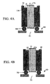
- Airtight testing is performed using fifteen sets of the optical component 20 and the optical component 10 (or optical component A9, see Embodiment 4 in FIG. 7) by use of a helium (He) leak detector 30 (produced by Shimadzu Manufacturing Co. Ltd.) as shown in FIGS. 4A and 4B. That is, the optical component A9 is arranged on an opening 31 of the helium leak detector 30 via an O-ring 32 as shown in FIG. 4A, and the optical component X is arranged on the opening 31 of the helium leak detector 30 via the O-ring 32 as shown in FIG. 4B.
- helium gas is blown towards the optical component A9 (or X) and is then sucked by the helium leak detector 30.
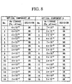
- FIG. 8 clearly shows that all samples belonging to the optical component A9 have good airtight property, whereas approximately one-third of samples belonging to the optical component X are deteriorated in airtight property.
- the optical component A9 has the chamfered portion 12a accompanied with the tapered portion 12b at one end of the metal lens holder 12 so that when the low melting point glass 13 is melted, it flows downwards along the tapered portion 12b due to gravity. As a result, the space defined by the tapered portion 12b is filled with the low melting point glass 13 while the airtight property is maintained.
- the chamfered portion 22a formed at one end of the metal lens holder 22 is not accompanied with the tapered portion, which deteriorates the wetness of the low melting point glass 13 brought into contact with the metal lens holder 22 and which also deteriorates the downward flow of the low melting point glass 13 in the chamfered portion 22a, whereby a non-filled area, which is not filled with the low melting point glass 13, may be formed between the optical lens 11 and the metal lens holder 22.
- the optical transmission element is composed of LaSF (i.e., a dense lanthanum flint) having a thermal expansion coefficient ( ⁇ 1) of 65 ⁇ 10 -7 /°C
- the joining material is made of a low melting point glass that is mainly composed of SiO 2 and B 2 O 3 having a thermal expansion coefficient (a2) of 70 ⁇ 10 -7 /°C and is added with PbO, so that the difference between the thermal expansion coefficients (i.e., ⁇ 2- ⁇ 1) is set to 5 ⁇ 10 -7 /°C
- the optical transmission element is composed of a borosilicate glass (SiO 2 +B 2 O 3 +Al 2 O 3 ) having a thermal expansion coefficient ( ⁇ 1) of 33 ⁇ 10 -7 /°C
- the joining material is made of a low melting point glass that is mainly composed of PbO (at 70% or so) having a thermal expansion coefficient ( ⁇ 2) of 40 ⁇ 10 -7 /
- the difference between the thermal expansion coefficients of the joining material and optical transmission element is not necessarily limited to 5 ⁇ 10 -7 /°C and 7 ⁇ 10 -7 /°C.
- the difference between the thermal expansion coefficients exceeds 50 ⁇ 10 -7 /°C, an excessive amount of compressive stress is imparted to the optical transmission element, in which cracks may easily occur and which may be deteriorated in optical characteristics such as the light extinction ratio.
- the optical transmission element is not necessarily limited to LaSF (i.e., dense lanthanum flint) and borosilicate glass (SiO 2 +B 2 O 3 +Al 2 O 3 ). That is, the optical transmission element is preferably selected from among the optical glass, optical crystal, and ceramics, in which the thermal expansion coefficient ( ⁇ 1) ranges from 60 ⁇ 10 -7 /°C to 80 ⁇ 10 -7 /°C. As the optical glass, it is preferable to selectively use TaF3 (tantalum flint glass, produced by HOYA Co.
- FK fluorosilicate crown
- PK phosphate crown
- ZK zinc crown
- BaK barium crown
- LaK lanthanum crown
- LF light flint
- SF doense flint
- LaF laflint
- quartz crystal rutile (titanium oxide), garnet, alumina (Al 2 O 3 ), lithium niobate (LiNbO 3 ), calcium fluoride (or fluorite) (CaF 2 ), lithium fluoride (LiF), magnesium fluoride (MgF 2 ), barium fluoride (BaF2), thallium iodobromide (KRS-5), thallium bromochloride (KRS-6), sodium chloride (NaCl), potassium bromide (KBr), potassium chloride (KCl), cesium iodide (CsI), and zinc selenide (ZnSe), etc.
- quartz crystal rutile (titanium oxide), garnet, alumina (Al 2 O 3 ), lithium niobate (LiNbO 3 ), calcium fluoride (or fluorite) (CaF 2 ), lithium fluoride (LiF), magnesium fluoride (MgF 2 ), barium flu
- the joining material is not necessarily limited to the low melting point glass, wherein it can be selected from among the organic adhesive, low melting point glass, and solder, in which the thermal expansion coefficient ( ⁇ 2) ranges between 70 ⁇ 10 -7 /°C and 90 ⁇ 10 -7 /°C.
- the organic adhesive is preferably selected from among polyimide adhesive, epoxy adhesive, UV (ultraviolet) adhesive, acrylic adhesive, and urethane adhesive, etc.
- the low melting point glass is mainly composed of SiO 2 and B 2 O 3 , which is preferably added with Al 2 O 3 , PbO, Na 2 O, K 2 O, BaO, Li 2 O, etc.
- the solder material it is preferable to selectively use the AuSn alloy solder, PbSn alloy solder, SnAgCu alloy solder, and the like.
- the aforementioned embodiments are designed such that the circumferential wall of the upper portion of the optical lens (or optical transmission element) 11 partially joins the metal holder 12 via the low melting point glass (or joining material), wherein the overall circumferential wall of the selected portion of the optical lens does not necessarily join the metal holder. That is, this invention can be actualized such that at least two positions of the circumferential wall of the optical lens 11 join the metal holder 12 via the low melting point glass.
- the aforementioned embodiments are designed to use a ring-like preform of the low melting point glass, which can be replaced with a paste-like low melting point glass.
Landscapes
- Physics & Mathematics (AREA)
- General Physics & Mathematics (AREA)
- Optics & Photonics (AREA)
- Lens Barrels (AREA)
- Glass Compositions (AREA)
- Optical Couplings Of Light Guides (AREA)
- Mounting And Adjusting Of Optical Elements (AREA)
Priority Applications (1)
| Application Number | Priority Date | Filing Date | Title |
|---|---|---|---|
| EP06022217A EP1742093A3 (fr) | 2003-09-19 | 2004-09-16 | Composant optique utilisant un élement de transmission optique joint à un support métallique |
Applications Claiming Priority (2)
| Application Number | Priority Date | Filing Date | Title |
|---|---|---|---|
| JP2003328452 | 2003-09-19 | ||
| JP2003328452A JP4491657B2 (ja) | 2003-09-19 | 2003-09-19 | 光学部品および金属ホルダ |
Related Child Applications (2)
| Application Number | Title | Priority Date | Filing Date |
|---|---|---|---|
| EP06022217A Division EP1742093A3 (fr) | 2003-09-19 | 2004-09-16 | Composant optique utilisant un élement de transmission optique joint à un support métallique |
| EP06022217.1 Division-Into | 2006-10-24 |
Publications (3)
| Publication Number | Publication Date |
|---|---|
| EP1517167A2 true EP1517167A2 (fr) | 2005-03-23 |
| EP1517167A3 EP1517167A3 (fr) | 2005-10-26 |
| EP1517167B1 EP1517167B1 (fr) | 2012-07-25 |
Family
ID=34191396
Family Applications (2)
| Application Number | Title | Priority Date | Filing Date |
|---|---|---|---|
| EP04022091A Expired - Lifetime EP1517167B1 (fr) | 2003-09-19 | 2004-09-16 | Méthode de fabrication d'un composant optique utilisant un élement de transmission optique joignant un support métallique |
| EP06022217A Withdrawn EP1742093A3 (fr) | 2003-09-19 | 2004-09-16 | Composant optique utilisant un élement de transmission optique joint à un support métallique |
Family Applications After (1)
| Application Number | Title | Priority Date | Filing Date |
|---|---|---|---|
| EP06022217A Withdrawn EP1742093A3 (fr) | 2003-09-19 | 2004-09-16 | Composant optique utilisant un élement de transmission optique joint à un support métallique |
Country Status (4)
| Country | Link |
|---|---|
| US (1) | US7313292B2 (fr) |
| EP (2) | EP1517167B1 (fr) |
| JP (1) | JP4491657B2 (fr) |
| CN (3) | CN100568036C (fr) |
Cited By (1)
| Publication number | Priority date | Publication date | Assignee | Title |
|---|---|---|---|---|
| CN103172277A (zh) * | 2011-12-23 | 2013-06-26 | 北京有色金属研究总院 | 一种光学玻璃与可伐合金的气密封接方法 |
Families Citing this family (7)
| Publication number | Priority date | Publication date | Assignee | Title |
|---|---|---|---|---|
| JPWO2012070286A1 (ja) * | 2010-11-24 | 2014-05-19 | アルプス電気株式会社 | レンズユニット |
| DE102012106289B4 (de) * | 2012-07-12 | 2016-10-27 | Schott Ag | Stablinse und Verfahren zu ihrer Herstellung |
| US11125966B2 (en) * | 2013-06-14 | 2021-09-21 | James Alan Monroe | Lens alignment system and method |
| KR102511623B1 (ko) * | 2018-04-11 | 2023-03-20 | 엘지이노텍 주식회사 | 카메라 모듈 |
| DE102019115204A1 (de) * | 2019-06-05 | 2020-12-10 | Schott Ag | Verfahren zur Herstellung eines Verbundelements und Verbundelement |
| KR102573838B1 (ko) * | 2020-04-09 | 2023-08-31 | 예놉틱 옵틱컬 시스템즈 게엠베하 | 유리 요소를 지지 요소에 열적으로 안정적으로 접합시키는 방법, 광학 디바이스를 제조하는 방법 및 광학 디바이스 |
| JP7602424B2 (ja) * | 2021-04-12 | 2024-12-18 | アルプスアルパイン株式会社 | 鏡筒付レンズ |
Family Cites Families (26)
| Publication number | Priority date | Publication date | Assignee | Title |
|---|---|---|---|---|
| DE1928240U (de) * | 1964-10-17 | 1965-12-02 | Rodenstock Optik G | Kraeftefreie pagerungsvorrichtung optischer elemente. |
| DD151230A1 (de) * | 1980-06-02 | 1981-10-08 | Gerhard Meister | Fassung fuer optische bauelemente |
| US4506951A (en) * | 1982-08-18 | 1985-03-26 | Olympus Optical Co., Ltd. | Plastic lens |
| JPS61223716A (ja) * | 1985-03-28 | 1986-10-04 | Olympus Optical Co Ltd | 光学部品の保持装置 |
| JP2645862B2 (ja) * | 1988-08-11 | 1997-08-25 | 株式会社日立製作所 | 半導体発光装置およびその応用製品 |
| JPH02281201A (ja) | 1989-04-24 | 1990-11-16 | Nec Corp | 集束性ロッドレンズの固定構造 |
| DE4118523A1 (de) * | 1991-02-19 | 1992-08-20 | Leica Industrieverwaltung | Axialsymmetrische fuegeverbindung hoher thermischer belastbarkeit |
| JPH06201962A (ja) * | 1992-12-28 | 1994-07-22 | Nippon Electric Glass Co Ltd | 光学用レンズ部品 |
| US5523893A (en) * | 1994-08-24 | 1996-06-04 | Northrop Grumman Corporation | Strain free temperature-compensated optical mounts |
| JPH08259262A (ja) | 1995-03-20 | 1996-10-08 | Nippon Electric Glass Co Ltd | 低融点封着用組成物 |
| JP4025387B2 (ja) * | 1997-03-31 | 2007-12-19 | フジノン株式会社 | プラスチックレンズ |
| US6031253A (en) * | 1997-09-30 | 2000-02-29 | Kyocera Corporation | Package for housing photosemiconductor device |
| JPH11110800A (ja) | 1997-10-03 | 1999-04-23 | Sony Corp | 光学ピックアップ装置 |
| US6269202B1 (en) * | 1997-10-10 | 2001-07-31 | Dicon Fiberoptics, Inc. | Highly temperature stable filter for fiberoptic applications and system for altering the wavelength or other characteristics of optical devices |
| DE19755356A1 (de) * | 1997-12-12 | 1999-06-17 | Zeiss Carl Fa | VUV-beständige Verbindungstechnik für Linsen und Fassungen |
| JP2000193892A (ja) * | 1998-12-25 | 2000-07-14 | Olympus Optical Co Ltd | 内視鏡 |
| WO2001061930A1 (fr) | 2000-02-21 | 2001-08-23 | Kabushiki Kaisha Toshiba | Dispositif de commande de moniteur et procede d'installation d'une voie de communication |
| WO2001099344A2 (fr) | 2000-06-14 | 2001-12-27 | Williams Communications, Llc | Desagregation des routes internet et etablissement de preferences dans la selection des routes |
| JP4095283B2 (ja) * | 2000-12-06 | 2008-06-04 | キヤノン株式会社 | レーザ装置 |
| JP2003040648A (ja) | 2001-07-30 | 2003-02-13 | Kyocera Corp | 光デバイス |
| US6574055B1 (en) * | 2001-10-08 | 2003-06-03 | Raytheon Company | Method and apparatus for effecting a temperature compensation movement |
| CN1278154C (zh) * | 2002-02-22 | 2006-10-04 | 日本电气硝子株式会社 | 光准直器用透镜部件、光准直器及它们的组装方法 |
| WO2003081313A2 (fr) * | 2002-03-18 | 2003-10-02 | Confluent Photonics Corporation | Technique de montage d'element optique |
| US7012757B2 (en) * | 2002-05-08 | 2006-03-14 | Be Here Corporation | Method for designing a lens system and resulting apparatus |
| DE10301265A1 (de) | 2003-01-15 | 2004-07-29 | Siemens Ag | Verfahren und Anordnung zum Routing von Datenpaketen in einem paketvermittelnden Datennetz |
| US7649834B2 (en) | 2004-09-15 | 2010-01-19 | At&T Intellectual Property Ii, L.P. | Method and apparatus for determining neighboring routing elements and rerouting traffic in a computer network |
-
2003
- 2003-09-19 JP JP2003328452A patent/JP4491657B2/ja not_active Expired - Fee Related
-
2004
- 2004-09-16 EP EP04022091A patent/EP1517167B1/fr not_active Expired - Lifetime
- 2004-09-16 US US10/941,940 patent/US7313292B2/en not_active Expired - Fee Related
- 2004-09-16 EP EP06022217A patent/EP1742093A3/fr not_active Withdrawn
- 2004-09-20 CN CNB2006100803513A patent/CN100568036C/zh not_active Expired - Fee Related
- 2004-09-20 CN CNB2006100803528A patent/CN100568037C/zh not_active Expired - Fee Related
- 2004-09-20 CN CN200410082528.4A patent/CN1288468C/zh not_active Expired - Fee Related
Non-Patent Citations (1)
| Title |
|---|
| None |
Cited By (1)
| Publication number | Priority date | Publication date | Assignee | Title |
|---|---|---|---|---|
| CN103172277A (zh) * | 2011-12-23 | 2013-06-26 | 北京有色金属研究总院 | 一种光学玻璃与可伐合金的气密封接方法 |
Also Published As
| Publication number | Publication date |
|---|---|
| CN100568036C (zh) | 2009-12-09 |
| CN1288468C (zh) | 2006-12-06 |
| EP1742093A3 (fr) | 2007-11-21 |
| EP1742093A2 (fr) | 2007-01-10 |
| CN100568037C (zh) | 2009-12-09 |
| US7313292B2 (en) | 2007-12-25 |
| US20050099703A1 (en) | 2005-05-12 |
| EP1517167A3 (fr) | 2005-10-26 |
| CN1601314A (zh) | 2005-03-30 |
| CN1877377A (zh) | 2006-12-13 |
| JP4491657B2 (ja) | 2010-06-30 |
| CN1877376A (zh) | 2006-12-13 |
| JP2005092088A (ja) | 2005-04-07 |
| EP1517167B1 (fr) | 2012-07-25 |
Similar Documents
| Publication | Publication Date | Title |
|---|---|---|
| JPWO2019151321A1 (ja) | 反射防止膜付ガラス基板及び光学部品 | |
| US7313292B2 (en) | Optical component using optical transmission element joining metal holder | |
| US6145731A (en) | Method for making a ceramic to metal hermetic seal | |
| US6392824B1 (en) | Soldering process for optical materials to metal mountings, and mounted assemblies | |
| AU651020B2 (en) | Athermal optical transmitter and method | |
| US5664040A (en) | Fiber optic assembly and method of making same | |
| US20220276467A1 (en) | Infrared imaging lens | |
| WO2021059622A1 (fr) | Élément de lentille, unité de lentille, et procédé de fabrication d'élément de lentille et unité de lentille | |
| JPS59155976A (ja) | ガスレ−ザ−とその製造方法 | |
| JPWO2012070286A1 (ja) | レンズユニット | |
| WO2020022002A1 (fr) | Composant optique | |
| US6922518B2 (en) | Methods and apparatus for sealed fiber optic feedthroughs | |
| EP0905480A2 (fr) | Jonction solide-liquide pour gyroscopes à laser circulaire | |
| JPH08130320A (ja) | 光半導体素子モジュールおよびその製造方法 | |
| Dietz | Optical fiber sealing with solder glass: design guidelines | |
| JP4756337B2 (ja) | 固体撮像素子用カバーガラス | |
| US6992844B2 (en) | System and method for providing a hermetically sealed lens and window assembly | |
| JP2003241048A (ja) | 光デバイス | |
| JPH0261604A (ja) | ロッドレンズの固定構造 | |
| JP2003040648A (ja) | 光デバイス | |
| JPH02281201A (ja) | 集束性ロッドレンズの固定構造 | |
| Dietz | Sealing optical fibers without metallization: design guidelines | |
| WO2006041074A1 (fr) | Verre de couverture pour dispositif de détection d’image solide et procédé de fabrication dudit verre | |
| Kreutzmann | Solder glass-sealing technology for use in packaging of fiber optic sensors | |
| JP2018087116A (ja) | ガラス管 |
Legal Events
| Date | Code | Title | Description |
|---|---|---|---|
| PUAI | Public reference made under article 153(3) epc to a published international application that has entered the european phase |
Free format text: ORIGINAL CODE: 0009012 |
|
| AK | Designated contracting states |
Kind code of ref document: A2 Designated state(s): AT BE BG CH CY CZ DE DK EE ES FI FR GB GR HU IE IT LI LU MC NL PL PT RO SE SI SK TR |
|
| AX | Request for extension of the european patent |
Extension state: AL HR LT LV MK |
|
| RIC1 | Information provided on ipc code assigned before grant |
Ipc: 7G 02B 7/00 B Ipc: 7G 02B 7/02 A |
|
| PUAL | Search report despatched |
Free format text: ORIGINAL CODE: 0009013 |
|
| AK | Designated contracting states |
Kind code of ref document: A3 Designated state(s): AT BE BG CH CY CZ DE DK EE ES FI FR GB GR HU IE IT LI LU MC NL PL PT RO SE SI SK TR |
|
| AX | Request for extension of the european patent |
Extension state: AL HR LT LV MK |
|
| RAP1 | Party data changed (applicant data changed or rights of an application transferred) |
Owner name: MITSUBISHI DENKI KABUSHIKI KAISHA Owner name: YAMAHA CORPORATION |
|
| 17P | Request for examination filed |
Effective date: 20060426 |
|
| AKX | Designation fees paid |
Designated state(s): DE FR GB IT SE |
|
| RAP1 | Party data changed (applicant data changed or rights of an application transferred) |
Owner name: MITSUBISHI DENKI KABUSHIKI KAISHA Owner name: YAMAHA CORPORATION |
|
| RAP1 | Party data changed (applicant data changed or rights of an application transferred) |
Owner name: MITSUBISHI DENKI KABUSHIKI KAISHA |
|
| RTI1 | Title (correction) |
Free format text: METHOD OF MANUFACTURING AN OPTICAL COMPONENT USING OPTICAL TRANSMISSION ELEMENT JOINING METAL HOLDER |
|
| GRAP | Despatch of communication of intention to grant a patent |
Free format text: ORIGINAL CODE: EPIDOSNIGR1 |
|
| RAP1 | Party data changed (applicant data changed or rights of an application transferred) |
Owner name: MITSUBISHI DENKI KABUSHIKI KAISHA |
|
| GRAS | Grant fee paid |
Free format text: ORIGINAL CODE: EPIDOSNIGR3 |
|
| RIN1 | Information on inventor provided before grant (corrected) |
Inventor name: HASHIMOTO, YOSHIHIRO C/O MITSUBISHI ELECTRIC ENGIN Inventor name: MATUOKA, KEN C/O MITSUBISHI DENKI K.K. Inventor name: SUZUKI, KATSUNORI C/O YAMAHA CORPORATION Inventor name: HAMANO, TETSUTSUGU C/O YAMAHA CORPORATION Inventor name: TAKAGI, SHINICHI C/O MITSUBISHI DENKI K.K. |
|
| GRAA | (expected) grant |
Free format text: ORIGINAL CODE: 0009210 |
|
| AK | Designated contracting states |
Kind code of ref document: B1 Designated state(s): DE FR GB IT SE |
|
| REG | Reference to a national code |
Ref country code: GB Ref legal event code: FG4D |
|
| REG | Reference to a national code |
Ref country code: SE Ref legal event code: TRGR |
|
| REG | Reference to a national code |
Ref country code: DE Ref legal event code: R096 Ref document number: 602004038629 Country of ref document: DE Effective date: 20120920 |
|
| PGFP | Annual fee paid to national office [announced via postgrant information from national office to epo] |
Ref country code: GB Payment date: 20120912 Year of fee payment: 9 Ref country code: SE Payment date: 20120911 Year of fee payment: 9 |
|
| PGFP | Annual fee paid to national office [announced via postgrant information from national office to epo] |
Ref country code: FR Payment date: 20120926 Year of fee payment: 9 Ref country code: DE Payment date: 20120829 Year of fee payment: 9 |
|
| PGFP | Annual fee paid to national office [announced via postgrant information from national office to epo] |
Ref country code: IT Payment date: 20120914 Year of fee payment: 9 |
|
| PLBE | No opposition filed within time limit |
Free format text: ORIGINAL CODE: 0009261 |
|
| STAA | Information on the status of an ep patent application or granted ep patent |
Free format text: STATUS: NO OPPOSITION FILED WITHIN TIME LIMIT |
|
| 26N | No opposition filed |
Effective date: 20130426 |
|
| REG | Reference to a national code |
Ref country code: DE Ref legal event code: R097 Ref document number: 602004038629 Country of ref document: DE Effective date: 20130426 |
|
| REG | Reference to a national code |
Ref country code: SE Ref legal event code: EUG |
|
| PG25 | Lapsed in a contracting state [announced via postgrant information from national office to epo] |
Ref country code: SE Free format text: LAPSE BECAUSE OF NON-PAYMENT OF DUE FEES Effective date: 20130917 |
|
| GBPC | Gb: european patent ceased through non-payment of renewal fee |
Effective date: 20130916 |
|
| REG | Reference to a national code |
Ref country code: DE Ref legal event code: R119 Ref document number: 602004038629 Country of ref document: DE Effective date: 20140401 |
|
| REG | Reference to a national code |
Ref country code: FR Ref legal event code: ST Effective date: 20140530 |
|
| PG25 | Lapsed in a contracting state [announced via postgrant information from national office to epo] |
Ref country code: GB Free format text: LAPSE BECAUSE OF NON-PAYMENT OF DUE FEES Effective date: 20130916 |
|
| PG25 | Lapsed in a contracting state [announced via postgrant information from national office to epo] |
Ref country code: FR Free format text: LAPSE BECAUSE OF NON-PAYMENT OF DUE FEES Effective date: 20130930 Ref country code: DE Free format text: LAPSE BECAUSE OF NON-PAYMENT OF DUE FEES Effective date: 20140401 Ref country code: IT Free format text: LAPSE BECAUSE OF NON-PAYMENT OF DUE FEES Effective date: 20130916 |