EP1516837B1 - Wechselvorrichtung and Verfahren zum Wechseln des Aufwickelns einer Bahn - Google Patents
Wechselvorrichtung and Verfahren zum Wechseln des Aufwickelns einer Bahn Download PDFInfo
- Publication number
- EP1516837B1 EP1516837B1 EP04022177A EP04022177A EP1516837B1 EP 1516837 B1 EP1516837 B1 EP 1516837B1 EP 04022177 A EP04022177 A EP 04022177A EP 04022177 A EP04022177 A EP 04022177A EP 1516837 B1 EP1516837 B1 EP 1516837B1
- Authority
- EP
- European Patent Office
- Prior art keywords
- web
- drum
- cutting
- receiving
- spindle
- Prior art date
- Legal status (The legal status is an assumption and is not a legal conclusion. Google has not performed a legal analysis and makes no representation as to the accuracy of the status listed.)
- Expired - Lifetime
Links
- 238000004804 winding Methods 0.000 title claims abstract description 23
- 238000000034 method Methods 0.000 title claims description 10
- 230000002093 peripheral effect Effects 0.000 claims abstract description 26
- 238000011144 upstream manufacturing Methods 0.000 claims description 30
- 239000000463 material Substances 0.000 claims description 18
- 239000000853 adhesive Substances 0.000 claims description 13
- 230000001070 adhesive effect Effects 0.000 claims description 13
- 238000007664 blowing Methods 0.000 claims description 3
- 239000002390 adhesive tape Substances 0.000 description 15
- 230000037303 wrinkles Effects 0.000 description 7
- 238000001514 detection method Methods 0.000 description 5
- 230000033001 locomotion Effects 0.000 description 3
- 229920002284 Cellulose triacetate Polymers 0.000 description 2
- NNLVGZFZQQXQNW-ADJNRHBOSA-N [(2r,3r,4s,5r,6s)-4,5-diacetyloxy-3-[(2s,3r,4s,5r,6r)-3,4,5-triacetyloxy-6-(acetyloxymethyl)oxan-2-yl]oxy-6-[(2r,3r,4s,5r,6s)-4,5,6-triacetyloxy-2-(acetyloxymethyl)oxan-3-yl]oxyoxan-2-yl]methyl acetate Chemical compound O([C@@H]1O[C@@H]([C@H]([C@H](OC(C)=O)[C@H]1OC(C)=O)O[C@H]1[C@@H]([C@@H](OC(C)=O)[C@H](OC(C)=O)[C@@H](COC(C)=O)O1)OC(C)=O)COC(=O)C)[C@@H]1[C@@H](COC(C)=O)O[C@@H](OC(C)=O)[C@H](OC(C)=O)[C@H]1OC(C)=O NNLVGZFZQQXQNW-ADJNRHBOSA-N 0.000 description 2
- 230000001419 dependent effect Effects 0.000 description 2
- 239000002184 metal Substances 0.000 description 2
- 229920000139 polyethylene terephthalate Polymers 0.000 description 2
- 239000005020 polyethylene terephthalate Substances 0.000 description 2
- 230000000717 retained effect Effects 0.000 description 2
- 230000005540 biological transmission Effects 0.000 description 1
- 239000011248 coating agent Substances 0.000 description 1
- 238000000576 coating method Methods 0.000 description 1
- 238000010276 construction Methods 0.000 description 1
- 239000000109 continuous material Substances 0.000 description 1
- 230000005484 gravity Effects 0.000 description 1
- 238000004519 manufacturing process Methods 0.000 description 1
- 239000000123 paper Substances 0.000 description 1
- 239000004033 plastic Substances 0.000 description 1
- 229920003023 plastic Polymers 0.000 description 1
- 239000002985 plastic film Substances 0.000 description 1
- 229920006255 plastic film Polymers 0.000 description 1
- -1 polyethylene terephthalate Polymers 0.000 description 1
Images






Classifications
-
- B—PERFORMING OPERATIONS; TRANSPORTING
- B65—CONVEYING; PACKING; STORING; HANDLING THIN OR FILAMENTARY MATERIAL
- B65H—HANDLING THIN OR FILAMENTARY MATERIAL, e.g. SHEETS, WEBS, CABLES
- B65H19/00—Changing the web roll
- B65H19/10—Changing the web roll in unwinding mechanisms or in connection with unwinding operations
- B65H19/20—Cutting-off the expiring web
-
- B—PERFORMING OPERATIONS; TRANSPORTING
- B65—CONVEYING; PACKING; STORING; HANDLING THIN OR FILAMENTARY MATERIAL
- B65H—HANDLING THIN OR FILAMENTARY MATERIAL, e.g. SHEETS, WEBS, CABLES
- B65H19/00—Changing the web roll
- B65H19/22—Changing the web roll in winding mechanisms or in connection with winding operations
- B65H19/26—Cutting-off the web running to the wound web roll
-
- B—PERFORMING OPERATIONS; TRANSPORTING
- B65—CONVEYING; PACKING; STORING; HANDLING THIN OR FILAMENTARY MATERIAL
- B65H—HANDLING THIN OR FILAMENTARY MATERIAL, e.g. SHEETS, WEBS, CABLES
- B65H19/00—Changing the web roll
- B65H19/10—Changing the web roll in unwinding mechanisms or in connection with unwinding operations
-
- B—PERFORMING OPERATIONS; TRANSPORTING
- B65—CONVEYING; PACKING; STORING; HANDLING THIN OR FILAMENTARY MATERIAL
- B65H—HANDLING THIN OR FILAMENTARY MATERIAL, e.g. SHEETS, WEBS, CABLES
- B65H19/00—Changing the web roll
- B65H19/22—Changing the web roll in winding mechanisms or in connection with winding operations
-
- B—PERFORMING OPERATIONS; TRANSPORTING
- B65—CONVEYING; PACKING; STORING; HANDLING THIN OR FILAMENTARY MATERIAL
- B65H—HANDLING THIN OR FILAMENTARY MATERIAL, e.g. SHEETS, WEBS, CABLES
- B65H19/00—Changing the web roll
- B65H19/22—Changing the web roll in winding mechanisms or in connection with winding operations
- B65H19/2207—Changing the web roll in winding mechanisms or in connection with winding operations the web roll being driven by a winding mechanism of the centre or core drive type
- B65H19/2215—Turret-type with two roll supports
-
- B—PERFORMING OPERATIONS; TRANSPORTING
- B65—CONVEYING; PACKING; STORING; HANDLING THIN OR FILAMENTARY MATERIAL
- B65H—HANDLING THIN OR FILAMENTARY MATERIAL, e.g. SHEETS, WEBS, CABLES
- B65H19/00—Changing the web roll
- B65H19/22—Changing the web roll in winding mechanisms or in connection with winding operations
- B65H19/28—Attaching the leading end of the web to the replacement web-roll core or spindle
- B65H19/283—Attaching the leading end of the web to the replacement web-roll core or spindle by applying adhesive to the core
-
- B—PERFORMING OPERATIONS; TRANSPORTING
- B65—CONVEYING; PACKING; STORING; HANDLING THIN OR FILAMENTARY MATERIAL
- B65H—HANDLING THIN OR FILAMENTARY MATERIAL, e.g. SHEETS, WEBS, CABLES
- B65H2301/00—Handling processes for sheets or webs
- B65H2301/40—Type of handling process
- B65H2301/41—Winding, unwinding
- B65H2301/417—Handling or changing web rolls
- B65H2301/4187—Relative movement of core or web roll in respect of mandrel
- B65H2301/4189—Cutting
- B65H2301/41892—Cutting knife located in winding or guiding roller and protruding therefrom
- B65H2301/418925—Cutting knife located in winding or guiding roller and protruding therefrom and cooperating with second assembly located in another roller
-
- B—PERFORMING OPERATIONS; TRANSPORTING
- B65—CONVEYING; PACKING; STORING; HANDLING THIN OR FILAMENTARY MATERIAL
- B65H—HANDLING THIN OR FILAMENTARY MATERIAL, e.g. SHEETS, WEBS, CABLES
- B65H2408/00—Specific machines
- B65H2408/20—Specific machines for handling web(s)
- B65H2408/23—Winding machines
- B65H2408/231—Turret winders
- B65H2408/2315—Turret winders specified by number of arms
- B65H2408/23152—Turret winders specified by number of arms with two arms
Definitions
- the present invention relates to a changeover device and method for changing over winding of a web. More particularly, the present invention relates to a changeover device and method for changing over winding of a web, in which the web with an extremely small thickness can be treated safely without breakage, wrinkles or other damages.
- JP-A 8-157112 and JP-A 11-171377 disclose an example of the web winder for automatically winding the web traveling continuously.
- JP-A 8-157112 cuts the web partially wound about a first spindle. After this, an upstream web section from the web is changed over to a second spindle, which continuously winds the upstream web section.
- a sheet applicator For the purpose of winding the web about the second spindle, an end of the upstream web section is attached by a sheet applicator to a leading sheet or guide leader extending from the second spindle.
- the sheet applicator must move at an equal speed to that of the web.
- the sheet applicator is stationary in the web winder.
- Part of the web being transported near to the sheet applicator is retained in a temporary manner by a nipping mechanism, for the purpose of the attachment.
- An accumulator is positioned upstream from the nipping mechanism, and stores the web transported during the attachment, so as to keep a continuous flow of the web.
- the web winder in JP-A 11-171377 , there is no use of the accumulator.
- the web winder automatically winds the web continuously transported.
- a nipping roll and a spindle nip the web.
- a portion of the web is cut on a cutting line downstream from the nipping position.
- the web is attached to the spindle with double-sided adhesive tape previously adhered to the spindle, for the purpose of changeover operation. Then rotation of the spindle winds the web.
- JP-A 11-171377 the web is cut at a cutting point that is in front of a position of attaching the adhesive tape. A front end of the web remains free in front of the attaching position. As the web is remarkably thin and has a low rigidity, the web may have wrinkles or folds in contact with the spindle.
- US-A-3 552 670 discloses a changeover device having the features which are indicated in the preamble of claim 1.
- an object of the present invention is to provide a changeover, device and method for changing over winding of a web, in which the web with an extremely small thickness can be treated safely without breakage, wrinkles or other damages.
- the web with an extremely small thickness can be treated safely without breakage, wrinkles or other damages, because of suitable operation of changeover by use of the cutting and receive drums and the drum support mechanism.
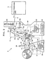
- a web winder 2 of a type of turret winder includes a changeover device 3 and a winder body 4.
- Various apparatuses are arranged in a film producing line 5.
- the web winder 2 is a finally used apparatus.
- a web 6 is wound about a selected one of first and second spindles 7a and 7b after continuous transport in the film producing line 5. It is noted that the web winder 2 can be used for other purposes, for example in a line for applying a coating.
- the winder body 4 has a frame or stand 10.
- Turret arms 11 and guide arms 12 are disposed on the stand 10 and are rotatable about a turret axis 13.
- Drive shafts 14 are incorporated in respectively an end of the turret arms 11.
- the drive shafts 14 are loaded with the first and second spindles 7a and 7b in a removable manner.
- the turret arms 11 are caused by a turret rotation control unit 16 with a motor to make half a rotation intermittently at each time of changeover of the web 6 to an unloaded spindle.
- the turret rotation control unit 16 is controlled by a controller 15 to cause the drive shafts 14 to rotate.
- An example of the turret rotation control unit 16 is constituted by a motor driver, a servo motor, and a motion transmitting mechanism, the servo motor including a rotary encoder.
- a first turret position is defined for a regular winding position where the first spindle 7a in Fig. 1 winds the web in the vicinity of the changeover device.
- Let a second turret position be an exchange position which is away from the changeover device and where the second spindle 7b is exchanged by a renewing operation.
- the turret arms make half a rotation, to change positions of the first and second spindles 7a and 7b to each other. See Fig. 2 .
- the first spindle 7a is removed from the drive shaft 14.
- a second spindle of an unloaded state is set on the drive shaft 14 in place of the first spindle 7a.
- a term of the fully wound state is used to refer to a state of the web roll having a predetermined diameter of the web 6 about a spindle.
- the controller 15 detects this state.
- the controller 15 considers a predetermined spindle diameter, and a predetermined thickness of the web 6, responds to a signal for the number of rotations output by the rotary encoder, and calculates the diameter of the web roll.
- Double-sided adhesive tape 17 with a tacky adhesive material is attached to the second spindle 7b in the unloaded state. See Fig. 5 .
- the web 6 can be attached to the second spindle 7b by use of the double-sided adhesive tape 17.
- the guide arms 12 rotate together with the turret arms 11.
- Guide rollers 18 are positioned on ends of the guide arms 12.
- the changeover device 3 includes a frame 19, a drum support arm 20, a dancer arm 21, the controller 15, a rotation control unit 22 with motors, and plural pass rolls 23.
- the drum support arm 20 is provided with a cutting drum 27, a receiving drum 28, plural pass rolls 29, and a tape detection sensor 30. Note that the tape detection sensor 30 may be disposed on the turret arms 11.
- An arm shaft 34 keeps the drum support arm 20 pivotally movable on the frame 19.
- a shifting cylinder 33 sets the drum support arm 20 in a selected one of a ready position of Fig. 1 and a changeover position of Fig. 2 .
- the changeover position for the drum support arm 20 is adjustable by an initial setting in consideration of a target diameter of a spindle.
- the pass rolls 29 guide the web 6 between the cutting drum 27 and the receiving drum 28.
- a form of the cutting and receiving drums 27 and 28 as viewed in a cross section is a sector shape.
- Drum shafts 39 and 40 of the drums keep those rotatable on the drum support arm 20. While the drums are stopped, the gap portions of those retreating from their peripheral surfaces operate as a path forming unit, with which the web 6 moves without contacting the drums. In contrast with this, while the drums rotate, drum peripheral surfaces 41 and 42 of Fig. 5 nip the web 6 being transported.
- a spindle surface 43 of the spindle of Fig. 5 and the drum peripheral surface 42 nip the web 6 in rotations of the receiving drum 28.
- the cutting drum 27 and the receiving drum 28 on the drum support arm 20 are rotated in synchronism by the rotation control unit 22 receiving a command signal from the controller 15.
- An example of the rotation control unit 22 is constituted by a motor driver, a servo motor, and a motion transmitting mechanism, the servo motor including a rotary encoder.
- the motor driver responds to the command signal from the controller 15, and determines a level of current or voltage according to which driving of the servo motor is controlled. Then the servo motor causes the cutting and receiving drums 27 and 28 to rotate.
- the broken lines indicate transmission of the force of driving.
- the pulse signals are counted in the controller 15, to obtain amounts of rotation of the cutting and receiving drums 27 and 28, for control of the cutting and receiving drums 27 and 28.
- the number of rotations of the cutting and receiving drums 27 and 28 is only one.
- the cutting drum 27 makes one clockwise rotation about the drum shaft 39.
- the receiving drum 28 makes one counterclockwise rotation about the drum shaft 40.
- Speeds of the cutting and receiving drums 27 and 28 are controlled so that peripheral speeds of those are equal to the web moving speed at the time of nipping.
- a clutch mechanism can be added to the rotation control unit 22, and can control the torque to be applied to the cutting and receiving drums 27 and 28 in driving the cutting and receiving drums 27 and 28.
- the cutting drum 27 is provided with a cutter 47 and plural air nozzles 48 with a blower or fan for the purpose of biasing the front end.
- the cutter 47 is set on the drum peripheral surface 41 in a direction parallel to the Drum shaft 39, or with an inclination of 0-5 degrees with reference to the direction of the drum shaft 39.
- the air nozzles 48 are positioned upstream from the cutting drum 27 in the rotational direction in the vicinity of the cutter.
- the air nozzles 48 are formed in the drum peripheral surface 41, and adapted for air blowing. Timing of the air blow is controlled by the controller 15.
- Surface material or lining material for the drum peripheral surface 41 is rubber. Note that a structure for biasing the front end of the web may be a sponge material, sponge rubber material or the like in place of the air nozzles 48. Furthermore, the surface material for the drum peripheral surface 41 may be metal, plastic, paper or the like instead of the rubber.
- the receiving slot 50 is formed in the drum peripheral surface 42, and extends in a direction parallel to the drum shaft 40 or with an inclination of 0-5 degrees as viewed from the drum shaft 40. This is similar to the inclination of the cutter 47 of the cutting drum 27.
- a lower portion of the inside of the receiving slot 50 is formed from metal, so as to cut the web 6 upon entry of the cutter 47 into the receiving slot 50.
- the suction mechanism 52 is positioned upstream from the receiving drum 28 in a rotational direction in the vicinity of the receiving slot 50.
- Plural holes are formed in the drum peripheral surface 42, and adapted for air suction of the suction mechanism 52, for the purpose of retaining a front end of the web by suction after the cutting. Timing of the air suction is controlled by the controller 15.
- Surface material or lining material for the drum peripheral surface 42 is rubber, so as to keep the surface of the second spindle 7b free from scratches even in incidental contact with the second spindle 7b.
- a dancer roll 54 is positioned at a first arm end of the dancer arm 21.
- a pivot 55 on the frame 19 keeps the dancer arm 21 rotatable about a second arm end.
- the dancer roll 54 has weight which applies prescribed tension to the web 6 under gravity.
- the dancer roll 54 moves up when a rotational speed of the drive shaft 14 becomes higher, and moves down when the rotational speed of the drive shaft 14 becomes lower.
- the dancer arm 21 is rotated about the pivot 55 by the moving up and down of the dancer roll 54.
- the potentiometer detects changes in the angle, and sends a detection signal to the controller 15.
- the controller 15 responsive to the detection signal controls a drive device associated with the drive shaft 14, to adjust the web moving speed of the web.
- the operation of the above construction is described.
- the web 6 produced by the film producing line 5 is transported in the arrow direction of Fig. 1 .
- the web 6 passes positions of the pass rolls 23 in the frame 19 and the pass rolls 29 on the drum support arm 20, and becomes wound by the first spindle 7a positioned regularly. If the web roll does not have the fully wound state yet, the drum support arm 20 is in the ready position of Fig. 1 .
- the web 6 is transported between the cutting drum 27 and the receiving drum 28. Gap portions are formed in respectively the cutting and receiving drums 27 and 28 to retreat from their peripheral surface, so the web 6 does not contact the cutting drum 27 or the receiving drum 28. While the web 6 becomes wound, the tension applied to the web 6 is controlled and kept constant.
- the controller 15 determines a diameter of the web roll according to the number of rotations of the first spindle 7a counted after the takeup of the web 6 to the first spindle 7a.
- the controller 15 generates a changeover signal. In Fig. 4 , this sequence is illustrated in a flow chart.
- the controller 15 sends a signal to the winder body 4, to cause the turret arms 11 and the guide arms 12 to make half a rotation in the clockwise direction.
- the second spindle 7b in the unloaded state is set in the first turret position with the double-sided adhesive tape 17 attached to the spindle surface.
- the second spindle 7b rotates at a peripheral speed that is equal to or slightly higher than a web moving speed of the web 6.
- the controller 15 sends a control signal to the shifting cylinder 33.
- the shifting cylinder 33 is driven, to shift the drum support arm 20 from the ready position to the changeover position.
- the controller 15 responds to a signal from the tape detection sensor 30, and generates a start command signal for starting rotations of the cutting drum 27 and the receiving drum 28.
- the start command signal is in such a form as to place and attach the front end of the upstream web section to the double-sided adhesive tape 17 after cutting.
- the cutting and receiving drums 27 and 28 are instantaneously accelerated, and rotated at the peripheral speed equal to the web moving speed.
- the web 6 is changed over from the first spindle 7a to the second spindle 7b in the unloaded state.
- Main elements of the web winder 2 will be hereinafter described by referring to Figs. 5-10 .
- the cutting drum 27 and the receiving drum 28 remain stopped.
- the web 6 is wound about the first spindle 7a that is in the second turret position.
- the web 6 becomes nipped between those at first.
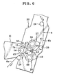
- the cutting and receiving drums 27 and 28 rotate further, the web 6 is also nipped between the second spindle 7b and the receiving drum 28. Note that the web 6, even while nipped, moves at the web moving speed equal to that at the time of being wound. Further rotations of the cutting and receiving drums 27 and 28 set the web 6 at a station between the cutter 47 of the cutting drum 27 and the receiving slot 50 of the receiving drum 28.
- the web 6 is squeezed and cut into a downstream web section 6a and an upstream web section 6b of Fig. 6 .
- the downstream web section 6a stands nipped between the second spindle 7b and the receiving drum 28.
- the upstream web section 6b stands nipped between the cutting and receiving drums 27 and 28.
- the downstream web section 6a is nipped at a point downstream from the cutting position. No unstable movement occurs to the cut end of the downstream web section 6a.
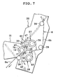
- the downstream web section 6a is transported while nipped between the second spindle 7b and the receiving drum 28. After the downstream web section 6a is released from being nipped between the second spindle 7b and the receiving drum 28, the downstream web section 6a is wound about the first spindle 7a. See Fig. 7 .
- the upstream web section 6b is thrust toward the receiving drum 28 upon application of biasing force of the blowing air from the air nozzles 48 to the front end of the upstream web section 6b, at the same time as the cutting.
- the suction unit or suction mechanism 52 at the receiving drum 28 air is sucked to retain the front end of the upstream web section 6b.
- the front end of the upstream web section 6b is transported by rotation of the receiving drum 28.
- Fig. 7 the front end becomes nipped between the receiving drum 28 and the second spindle 7b in the unloaded state.
- the front end of the upstream web section 6b is placed on and connected with the double-sided adhesive tape 17 on the second spindle 7b.
- the front end of the upstream web section 6b remains attached on the second spindle 7b.
- the upstream web section 6b becomes wound about the second spindle 7b.
- the drum support arm 20 remains in the changeover position until a portion of the upstream web section 6b being wound on the second spindle 7b comes up to a predetermined amount.
- the controller 15 sends a control signal to the shifting cylinder 33.
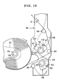
- the drum support arm 20 shifts from the changeover position to the ready position. After this, the upstream web section 6b is wound until the web roll comes to have the fully wound state in Fig. 10 . Similar operation is repeated until the transport of the web 6 is stopped.
- the form of the cutting drum 27 and the receiving drum 28 as viewed in a cross section is a sector shape.
- the form of those as viewed in a cross section can be circular as illustrated in Fig. 11 .
- the drum shaft 39 may be moved by a sliding mechanism 60 or other a drum retracting mechanism, in an upward direction in the drawing sheet. This is a path forming unit in place of the drum shaft 39 defined as a surface of the cutout portion according to the above embodiment.
- the receiving drum 28 may be moved away at the same time as the cutting drum 27 is moved.
- the double-sided adhesive tape 17 is previously placed on the second spindle 7b. However, it is also possible to set the double-sided adhesive tape 17 previously on the cutting drum 27. In this case, the double-sided adhesive tape 17 is stuck to the drum peripheral surface 41 in the vicinity of the cutter. The double-sided adhesive tape 17 is provided with force of adhesion higher on an adhesion surface to the web than on an adhesion surface for sticking to the cutting drum. At the time of release of the nipping of the upstream web section 6b from the cutting drum 27 and the receiving drum 28, the force of suction of the suction mechanism 52 is set high.
- the force of suction of the suction mechanism 52 is set low.
- the double-sided adhesive tape. 17 is attached to the upstream web section 6b.
- the upstream web section 6b when released from nipping between the cutting and receiving drums 27 and 28, is retained on the receiving drum 28 by suction together with the double-sided adhesive tape 17.
- the upstream web section 6b becomes nipped between the second spindle 7b and the receiving drum 28.
- One surface of the double-sided adhesive tape 17 is attached to the second spindle 7b, about which the upstream web section 6b is wound.
- the web 6 was formed from material of triacetyl cellulose (TAC), had a thickness of 40 microns, a web width of 1,500 mm, and tension to be applied to the web 6 was 100 N per unit width of the web 6.
- the web moving speed of the web 6 was 30/min.
- Diameters of the first and second spindles 7a and 7b were 169 mm as equal diameters.
- Diameters of the cutting drum 27 and the receiving drum 28 were 300 mm as equal diameters.
- the turret rotation control unit 16 had a width of 10 mm, and a length of 30 mm. Pressure of nipping of the receiving drum 28 to the spindle was 0.2 MPa. Results were checked.
- the web 6 was safely changed over from the first spindle 7a to the second spindle 7b by smooth changeover without occurrence of wrinkles, breakage or folds.
- the web 6 was formed from material of polyethylene terephthalate (PET), had a thickness of 180 microns, a web width of 1,200 mm, and tension to be applied to the web 6 was 300 N per unit width of the web 6.
- the web moving speed of the web 6 was 100/min.
- Diameters of the first and second spindles 7a and 7b were 300 mm as equal diameters.
- Diameters of the cutting drum 27 and the receiving drum 28 were 300 mm as equal diameters.
- the turret rotation control unit 16 had a width of 10 mm, and a length of 30 mm. Pressure of nipping of the receiving drum 28 to the spindle was 0.2 MPa. Results were checked. Again, the web 6 was safely changed over from the first spindle 7a to the second spindle 7b by smooth changeover without occurrence of wrinkles, breakage or folds.
Landscapes
- Replacement Of Web Rolls (AREA)
Claims (14)
- Eine Umschaltvorrichtung zum Umschalten des Aufwickelns einer Bahn (6), die um eine erste Spindel (7a) aufgewickelt ist, zum Aufwickeln um eine zweite Spindel (7b) in einer Bahnwickelvorrichtung (2) des Revolverkopf-Aufwickeltyps, wobei die erste Spindel an einer ersten Antriebswelle (14) befestigt ist, die zweite Spindel an einer zweiten Antriebswelle (14) befestigt ist, und die Positionen der ersten und der zweiten Antriebswelle in der Bahnwickelvorrichtung austauschbar sind, wobei die Umschaltvorrichtung aufweist:eine Schneidtrommel (27), die an einer ersten Seite in Bezug auf einen Bahnweg (23, 29) der Bahn angeordnet ist, und eine Schneidvorrichtung (47) zum Schneiden der Bahn in Richtung von deren Breite aufweist;eine Aufnahmetrommel (28), die an einer zweiten Seite in Bezug auf den Bahnweg entgegengesetzt zur ersten Seite angeordnet ist; undeinen Trommelhalterungsmechanismus (20) zum Haltern der Schneid- und Aufnahmetrommeln so, dass sie sich drehen können, und Trommelumfangsoberflächen (41, 42) der Schneid- und Aufnahmetrommeln miteinander in Berührung gelangen können;dadurch gekennzeichnet, dassdie Schneidtrommel (27) und die Aufnahmetrommel (28) jeweils einen Abschnitt (39; 40) mit kleinem Radius aufweisen, der nicht in Kontakt mit der Bahn (6) steht;eine Umsetzvorrichtung (33) vorgesehen ist, um den Trommelhalterungsmechanismus (20) zwischen einer Umschaltposition, um die Trommelumfangsoberfläche (42) der Aufnahmetrommel (28) dazu zu veranlassen, in Kontakt mit der zweiten Spindel (7b) zu gelangen, und einer Bereitschaftsposition umzusetzen, damit die Trommelumfangsoberfläche der Aufnahmetrommel entfernt von der Bahn (6) bleibt, die um die zweite Spindel herum aufgewickelt wird;eine Wegausbildungseinheit (39, 40, 60) zwischen der Schneid- und der Aufnahmetrommel (27, 28) angeordnet ist, um es der Bahn zu ermöglichen, berührungslos in Bezug auf die Schneid- bzw. die Aufnahmetrommel hindurchzugehen; undeine Drehsteuereinheit (22) vorgesehen ist, die betätigt wird, wenn der Trommelhalterungsmechanismus (20) auf die Umschaltposition eingestellt ist, um die Schneid- bzw. Aufnahmetrommel (27, 28) dazu zu veranlassen, dass sie eine Drehung durchführen.
- Umschaltvorrichtung nach Anspruch 1, bei welcher die Drehsteuereinheit (22) die Schneid- bzw. Aufnahmetrommel (27, 28) dazu veranlasst, sich mit eine Umfangsgeschwindigkeit gleich einer Bahnbewegungsgeschwindigkeit der Bahn (6) zu drehen.
- Umschaltvorrichtung nach Anspruch 1, bei welcher die Wegausbildungseinheit (39, 40, 60) einen Mechanismus (60) zum Bewegen der Schneidtrommel (27) weg von der Aufnahmetrommel (28) aufweist.
- Umschaltvorrichtung nach Anspruch 1, bei welcher die Bahn (6) mit einem Klebematerial (17) an eine der Spindeln (7a, 7b) angeklebt wird.
- Umschaltvorrichtung nach Anspruch 1, bei welcher ein Klebefolienmaterial (17) an der Schneidtrommel (27) anhaftend befestigt wird, zum Ankleben der Bahn (6) an eine der Spindeln (7a, 7b), und das Klebefolienmaterial eine erste Klebeoberfläche zum Ankleben an der Schneidtrommel aufweist, und eine zweite Klebeoberfläche, die eine höhere Haftfestigkeit aufweist, als die erste Klebeoberfläche, zum Ankleben an die Bahn.
- Umschaltvorrichtung nach Anspruch 1, bei welcher die Schneidvorrichtung (47) gegenüber der Trommelumfangsoberfläche (41) der Schneidtrommel (27) vorsteht, und die Aufnahmetrommel (28) einen Aufnahmeschlitz (50) zur Aufnahme des Zugangs der Schneidvorrichtung aufweist.
- Umschaltvorrichtung nach Anspruch 6, bei welcher die Aufnahmetrommel (28) ein Oberflächenmaterial aus Gummi aufweist, dass auf ihrer Trommelumfangsoberfläche (42) angeordnet ist.
- Umschaltvorrichtung nach Anspruch 7, welche weiterhin eine Saugeinheit (52) aufweist, zum Ansaugen der Bahn (6) nahe einem stromaufwärtigen Rand des Aufnahmeschlitzes (50) stromaufwärts in Bezug auf die Trommeldrehrichtung der Aufnahmetrommel (28).
- Umschaltvorrichtung nach Anspruch 8, welche weiterhin eine Vorderend-Vorspanneinheit (48) aufweist, die nahe an einer stromaufwärtigen Seite der Schneidvorrichtung (47) stromaufwärts in Bezug auf die Trommeldrehrichtung der Schneidtrommel (27) angeordnet ist, um ein Vorderende der Bahn (6) vorzuspannen, das zu der Aufnahmetrommel (28) hin geschnitten wird.
- Umschaltvorrichtung nach Anspruch 9, bei welcher die Vorderend-Vorspanneinheit (48) einen Luftblasmechanismus oder ein Spannmaterial aufweist.
- Umschaltvorrichtung nach Anspruch 1, bei welcher die Bahnwickelvorrichtung (2) aufweist:zumindest einen ersten und einen zweiten Revolverkopfarm (11), die so angeordnet sind, dass sie sich in Radialrichtung von einer Revolverkopfachse (13) erstrecken, zum Haltern der ersten bzw. zweiten Antriebswelle (14) an ihrem jeweiligen Ende;eine Revolverkopf-Drehsteuereinrichtung (16) zur Einstellung des ersten und des zweiten Revolverkopfes selektiv auf eine erste und zweite Revolverkopfposition durch Drehung um die Revolverkopfachse;eine Steuerung (15) zum Betrieb in einem ersten bzw. zweiten Schritt alternativ;wobei die Steuerung in dem ersten Schritt die erste Antriebswelle auf dem ersten Revolverkopfarm in der ersten Revolverkopfposition so steuert, dass die Bahn (6) um die erste Spindel (7a) aufgewickelt wird, wobei die zweite Revolverkopfposition dazu ausgebildet ist, am Anfang die zweite Spindel (7b) in einen unbenutzten Zustand zu versetzen;die Steuerung in dem zweiten Schritt die Revolverkopfdrehsteuereinheit zur Dreheinstellung des zweiten Revolverkopfarms auf die erste Revolverkopfposition antreibt, und zur Dreheinstellung des ersten Revolverkopfarms auf die zweite Revolverkopfposition, um das Abnehmen einer Rolle der Bahn zu ermöglichen, die aufgewickelt wurde, von der ersten Antriebswelle;wobei die erste Aufnahmetrommel (28) in der Nähe der ersten Revolverkopfposition angeordnet ist, und der Trommelhalterungsmechanismus (20) auf die zweite Umschaltposition eingestellt ist, nach dem zweiten Schritt und vor dem ersten Schritt.
- Umschaltverfahren zum Umschalten des Aufwickelns einer Bahn (6), die um eine erste Spindel (7a) aufgewickelt wird, zum Aufwickeln um eine zweite Spindel (7b) in einer Bahnwickelvorrichtung (2) des Revolverkopf-Aufwickeltyps, wobei die erste Spindel an einer ersten Antriebswelle (14) befestigt ist, die zweite Spindel an einer zweiten Antriebswelle (14) befestigt ist, Positionen der ersten und der zweiten Antriebswelle in der Bahnwickelvorrichtung geändert werden können, wobei das Umschaltverfahren folgende Schritte umfasst:Verbindung einer Schneidtrommel (27) und einer Aufnahmetrommel (28), wobei die Schneidtrommel an einer ersten Seite in Bezug auf einen Bahnweg (23, 29) der Bahn angeordnet ist, und eine Schneidvorrichtung (47) zum Schneiden der Bahn in Richtung ihrer Breite aufweist, und einen Abschnitt (39) mit kleinem Radius, der frei von Kontakt mit der Bahn ist, wobei die Aufnahmetrommel an einer zweiten Seite in Bezug auf den Bahnweg entgegengesetzt zur ersten Seite angeordnet ist, und einen Abschnitt (40) mit kleinem Radius aufweist, der frei von Kontakt mit der Bahn ist;Haltern der Schneid- und Aufnahmetrommeln durch einen Trommelhalterungsmechanismus (20) so, dass diese sich drehen können, und auf solche Art und Weise, dass Trommelumfangsoberflächen (41, 42) der Schneid- und Aufnahmetrommeln miteinander in Kontakt stehen;Anhalten der Schneid- und Aufnahmetrommel, wenn deren Trommelumfangsoberflächen einander gegenüberliegen, um einen Raum zum Durchgang der Bahn auf berührungslose Art und Weise auszubilden;Verschieben des Trommelhalterungsmechanismus zwischen einer Umschaltposition zum Veranlassen der Trommelumfangsoberfläche (47) der Aufnahmetrommel so, dass sie in Kontakt mit der zweiten Spindel gerät, und einer Bereitschaftsposition zum Halten der Trommelumfangsoberfläche der Aufnahmetrommel weg von der Bahn, die um die zweite Spindel herum aufgewickelt wird;nach Einstellung des Trommelhalterungsmechanismus auf die Umschaltposition, veranlassen, dass die Schneid- und Aufnahmetrommeln eine Drehung durchführen, um die Bahn zu schneiden; undBefestigen eines Vorderendes der Bahn, die durch Schneiden ausgebildet wird, an der zweiten Spindel, zur Umschaltung des Aufwickelns.
- Umschaltverfahren nach Anspruch 12, bei welchem die Bahn mit einem Klebematerial (17) an einer der Spindeln (7b) angeklebt wird.
- Umschaltverfahren nach Anspruch 12, bei welchem ein Klebefolienmaterial (17) an der Schneidtrommel (27) angebracht wird, zum Ankleben der Bahn (6) an die zweite Spindel (7b), und das Klebefolienmaterial eine erste Klebeoberfläche zum Ankleben an der Schneidtrommel aufweist, und eine zweite Klebeoberfläche, die eine höhere Klebekraft aufweist als die erste Klebeoberfläche, zum Ankleben an der Bahn.
Applications Claiming Priority (2)
| Application Number | Priority Date | Filing Date | Title |
|---|---|---|---|
| JP2003328955 | 2003-09-19 | ||
| JP2003328955A JP4136864B2 (ja) | 2003-09-19 | 2003-09-19 | ウェブ巻替え装置及び方法 |
Publications (2)
| Publication Number | Publication Date |
|---|---|
| EP1516837A1 EP1516837A1 (de) | 2005-03-23 |
| EP1516837B1 true EP1516837B1 (de) | 2008-04-23 |
Family
ID=34191408
Family Applications (1)
| Application Number | Title | Priority Date | Filing Date |
|---|---|---|---|
| EP04022177A Expired - Lifetime EP1516837B1 (de) | 2003-09-19 | 2004-09-17 | Wechselvorrichtung and Verfahren zum Wechseln des Aufwickelns einer Bahn |
Country Status (7)
| Country | Link |
|---|---|
| US (1) | US7264193B2 (de) |
| EP (1) | EP1516837B1 (de) |
| JP (1) | JP4136864B2 (de) |
| KR (1) | KR101155362B1 (de) |
| AT (1) | ATE393112T1 (de) |
| DE (1) | DE602004013241T2 (de) |
| TW (1) | TWI332933B (de) |
Families Citing this family (19)
| Publication number | Priority date | Publication date | Assignee | Title |
|---|---|---|---|---|
| JP4922799B2 (ja) * | 2007-03-16 | 2012-04-25 | 富士フイルム株式会社 | ウェブ巻替え装置及び方法 |
| CN101970321B (zh) * | 2007-10-16 | 2014-04-09 | 格罗特斯工程公司 | 索引卷绕机上卷绕芯的设备 |
| EP2296867B1 (de) * | 2008-04-23 | 2015-05-27 | MICHELIN Recherche et Technique S.A. | Verfahren zum bilden einer mehrlagigen reifenkomponente |
| EP2465799A1 (de) | 2010-12-15 | 2012-06-20 | SAS Mondon | Wicklungsvorrichtung |
| US9566193B2 (en) * | 2011-02-25 | 2017-02-14 | Curt G. Joa, Inc. | Methods and apparatus for forming disposable products at high speeds with small machine footprint |
| JP5661558B2 (ja) * | 2011-05-24 | 2015-01-28 | 合資会社オリエンタル | 古紙再生装置用巻取り機構及び古紙再生装置 |
| JP5972002B2 (ja) * | 2012-03-26 | 2016-08-17 | 株式会社ジェイテクト | ウエブ巻取装置 |
| JP5959259B2 (ja) * | 2012-03-26 | 2016-08-02 | 株式会社ジェイテクト | ウエブ巻取装置 |
| US9216924B2 (en) | 2012-11-09 | 2015-12-22 | Corning Incorporated | Methods of processing a glass ribbon |
| JP6047517B2 (ja) * | 2014-03-28 | 2016-12-21 | 富士フイルム株式会社 | ウェブ巻替え装置及び方法 |
| CN103991735B (zh) * | 2014-04-16 | 2016-04-20 | 苏州市雄林新材料科技有限公司 | 一种双工位中心卷取装置 |
| CN104310094A (zh) * | 2014-11-07 | 2015-01-28 | 江苏龙达转移印花纺织品有限公司 | 印纸机收纸装置 |
| EP3362389A4 (de) | 2015-10-13 | 2019-07-10 | Curt G. Joa, Inc. | Einwegproduktanordnungssysteme und -verfahren |
| CN105347082A (zh) * | 2015-11-19 | 2016-02-24 | 湖南省客来宝生物能源科技有限公司 | 一种生物降解膜用卷膜机 |
| CN111573357B (zh) * | 2020-05-26 | 2022-06-07 | 南通博凯自动化设备有限公司 | 一种基于厚度变化定量绕卷且自动切割的纸张绕卷装置 |
| CN111891805B (zh) * | 2020-09-10 | 2022-03-04 | 浙江天祥新材料股份有限公司 | 一种布料压紧式收卷装置 |
| EP4357280B1 (de) * | 2022-09-05 | 2025-06-04 | Contemporary Amperex Technology (Hong Kong) Limited | Auf- und abwickelvorrichtung, und elektrodenplattenvorbereitungssystem |
| CN115893067B (zh) * | 2023-02-09 | 2023-10-27 | 江苏好健康新材料有限公司 | 一种木浆原纸生产用收卷装置 |
| CN117163707B (zh) * | 2023-07-29 | 2026-01-27 | 上海宇泽机电设备有限公司 | 一种双轴收卷结构 |
Family Cites Families (9)
| Publication number | Priority date | Publication date | Assignee | Title |
|---|---|---|---|---|
| US3552670A (en) * | 1968-06-12 | 1971-01-05 | Scott Paper Co | Web winding apparatus |
| US4529141A (en) * | 1984-01-13 | 1985-07-16 | Imd Corporation | Method and apparatus for rewinding, severing and transferring web-like material |
| JPS6360848A (ja) * | 1986-08-29 | 1988-03-16 | Fuji Photo Film Co Ltd | ウエブ巻取り方法並びにその装置 |
| JP2809254B2 (ja) * | 1992-12-03 | 1998-10-08 | 富士写真フイルム株式会社 | ウエブの突合わせ接合装置 |
| US5368253A (en) * | 1993-04-23 | 1994-11-29 | Faustel Incorporated | Continuous rewind with no-fold-back splicer |
| US5660349A (en) * | 1994-05-16 | 1997-08-26 | Paper Converting Machine Company | Method and apparatus for winding coreless rolls |
| JPH08157112A (ja) | 1994-10-06 | 1996-06-18 | Kyodo Printing Co Ltd | ウェブ巻取装置および巻取方法 |
| JP3584456B2 (ja) | 1996-11-08 | 2004-11-04 | 富士写真フイルム株式会社 | 可撓性帯状材の接合方法及びその接合装置 |
| JP3558845B2 (ja) | 1997-12-12 | 2004-08-25 | 三菱製紙株式会社 | ウエブ巻取方法及びその装置 |
-
2003
- 2003-09-19 JP JP2003328955A patent/JP4136864B2/ja not_active Expired - Fee Related
-
2004
- 2004-09-16 US US10/941,854 patent/US7264193B2/en not_active Expired - Lifetime
- 2004-09-17 AT AT04022177T patent/ATE393112T1/de not_active IP Right Cessation
- 2004-09-17 TW TW093128129A patent/TWI332933B/zh not_active IP Right Cessation
- 2004-09-17 EP EP04022177A patent/EP1516837B1/de not_active Expired - Lifetime
- 2004-09-17 DE DE602004013241T patent/DE602004013241T2/de not_active Expired - Lifetime
- 2004-09-18 KR KR1020040074841A patent/KR101155362B1/ko not_active Expired - Fee Related
Also Published As
| Publication number | Publication date |
|---|---|
| DE602004013241T2 (de) | 2009-06-25 |
| ATE393112T1 (de) | 2008-05-15 |
| US7264193B2 (en) | 2007-09-04 |
| DE602004013241D1 (de) | 2008-06-05 |
| KR20050028884A (ko) | 2005-03-23 |
| EP1516837A1 (de) | 2005-03-23 |
| JP4136864B2 (ja) | 2008-08-20 |
| US20050077415A1 (en) | 2005-04-14 |
| TW200517326A (en) | 2005-06-01 |
| KR101155362B1 (ko) | 2012-06-19 |
| TWI332933B (en) | 2010-11-11 |
| JP2005089177A (ja) | 2005-04-07 |
Similar Documents
| Publication | Publication Date | Title |
|---|---|---|
| EP1516837B1 (de) | Wechselvorrichtung and Verfahren zum Wechseln des Aufwickelns einer Bahn | |
| JP4922799B2 (ja) | ウェブ巻替え装置及び方法 | |
| JP3863198B2 (ja) | 巻取り装置及び巻取り方法 | |
| US20070278341A1 (en) | Strip continuous supply method and apparatus | |
| JP2002308485A (ja) | 帯状体連続供給装置の制御方法及びその装置 | |
| CN1154607C (zh) | 单个工位连续圆卷材卷绕系统及其卷绕方法 | |
| EP1648805B1 (de) | Verfahren und vorrichtung zum spleissen von bahnen | |
| JP2809254B2 (ja) | ウエブの突合わせ接合装置 | |
| JP2010036990A (ja) | ウェブ巻取り装置及び方法 | |
| JP5930828B2 (ja) | 巻取装置 | |
| US6264130B1 (en) | Duplex web roll winding and splicing apparatus | |
| CN113911791A (zh) | 转塔放卷机构、其接料单元及其尾料控制方法 | |
| JP3199079B2 (ja) | 長尺体の巻取方法及びその装置 | |
| JP6047517B2 (ja) | ウェブ巻替え装置及び方法 | |
| CN111252604B (zh) | 一种料带走带装置及走带方法 | |
| CN116443641A (zh) | 一种铝箔分切机 | |
| US4129265A (en) | Reeled web unwind stand | |
| KR100412323B1 (ko) | 그라비아 인쇄기의 언와인더 스플라이싱 조정장치 | |
| US3768746A (en) | Apparatus for joining continuously moving web material | |
| JP4491740B2 (ja) | 微粘着帯状シートの巻取方法及び巻取装置 | |
| JP2767932B2 (ja) | ウエブの搬送方法及び装置 | |
| JP2003146500A (ja) | ウエブ押付装置 | |
| JPH06115776A (ja) | シート供給装置 | |
| NL1035313C2 (nl) | Een folieverbindingsinrichting. | |
| JPH03192056A (ja) | ウェブ供給装置 |
Legal Events
| Date | Code | Title | Description |
|---|---|---|---|
| PUAI | Public reference made under article 153(3) epc to a published international application that has entered the european phase |
Free format text: ORIGINAL CODE: 0009012 |
|
| AK | Designated contracting states |
Kind code of ref document: A1 Designated state(s): AT BE BG CH CY CZ DE DK EE ES FI FR GB GR HU IE IT LI LU MC NL PL PT RO SE SI SK TR |
|
| AX | Request for extension of the european patent |
Extension state: AL HR LT LV MK |
|
| 17P | Request for examination filed |
Effective date: 20050902 |
|
| AKX | Designation fees paid |
Designated state(s): AT BE BG CH CY CZ DE DK EE ES FI FR GB GR HU IE IT LI LU MC NL PL PT RO SE SI SK TR |
|
| RAP1 | Party data changed (applicant data changed or rights of an application transferred) |
Owner name: FUJIFILM CORPORATION |
|
| 17Q | First examination report despatched |
Effective date: 20070515 |
|
| GRAP | Despatch of communication of intention to grant a patent |
Free format text: ORIGINAL CODE: EPIDOSNIGR1 |
|
| GRAS | Grant fee paid |
Free format text: ORIGINAL CODE: EPIDOSNIGR3 |
|
| GRAA | (expected) grant |
Free format text: ORIGINAL CODE: 0009210 |
|
| AK | Designated contracting states |
Kind code of ref document: B1 Designated state(s): AT BE BG CH CY CZ DE DK EE ES FI FR GB GR HU IE IT LI LU MC NL PL PT RO SE SI SK TR |
|
| REG | Reference to a national code |
Ref country code: GB Ref legal event code: FG4D |
|
| REG | Reference to a national code |
Ref country code: CH Ref legal event code: EP |
|
| REF | Corresponds to: |
Ref document number: 602004013241 Country of ref document: DE Date of ref document: 20080605 Kind code of ref document: P |
|
| REG | Reference to a national code |
Ref country code: IE Ref legal event code: FG4D Free format text: LANGUAGE OF EP DOCUMENT: FRENCH |
|
| PG25 | Lapsed in a contracting state [announced via postgrant information from national office to epo] |
Ref country code: SI Free format text: LAPSE BECAUSE OF FAILURE TO SUBMIT A TRANSLATION OF THE DESCRIPTION OR TO PAY THE FEE WITHIN THE PRESCRIBED TIME-LIMIT Effective date: 20080423 |
|
| PG25 | Lapsed in a contracting state [announced via postgrant information from national office to epo] |
Ref country code: BG Free format text: LAPSE BECAUSE OF FAILURE TO SUBMIT A TRANSLATION OF THE DESCRIPTION OR TO PAY THE FEE WITHIN THE PRESCRIBED TIME-LIMIT Effective date: 20080723 Ref country code: ES Free format text: LAPSE BECAUSE OF FAILURE TO SUBMIT A TRANSLATION OF THE DESCRIPTION OR TO PAY THE FEE WITHIN THE PRESCRIBED TIME-LIMIT Effective date: 20080803 Ref country code: PT Free format text: LAPSE BECAUSE OF FAILURE TO SUBMIT A TRANSLATION OF THE DESCRIPTION OR TO PAY THE FEE WITHIN THE PRESCRIBED TIME-LIMIT Effective date: 20080923 Ref country code: FI Free format text: LAPSE BECAUSE OF FAILURE TO SUBMIT A TRANSLATION OF THE DESCRIPTION OR TO PAY THE FEE WITHIN THE PRESCRIBED TIME-LIMIT Effective date: 20080423 |
|
| PG25 | Lapsed in a contracting state [announced via postgrant information from national office to epo] |
Ref country code: PL Free format text: LAPSE BECAUSE OF FAILURE TO SUBMIT A TRANSLATION OF THE DESCRIPTION OR TO PAY THE FEE WITHIN THE PRESCRIBED TIME-LIMIT Effective date: 20080423 Ref country code: AT Free format text: LAPSE BECAUSE OF FAILURE TO SUBMIT A TRANSLATION OF THE DESCRIPTION OR TO PAY THE FEE WITHIN THE PRESCRIBED TIME-LIMIT Effective date: 20080423 |
|
| PG25 | Lapsed in a contracting state [announced via postgrant information from national office to epo] |
Ref country code: DK Free format text: LAPSE BECAUSE OF FAILURE TO SUBMIT A TRANSLATION OF THE DESCRIPTION OR TO PAY THE FEE WITHIN THE PRESCRIBED TIME-LIMIT Effective date: 20080423 Ref country code: SE Free format text: LAPSE BECAUSE OF FAILURE TO SUBMIT A TRANSLATION OF THE DESCRIPTION OR TO PAY THE FEE WITHIN THE PRESCRIBED TIME-LIMIT Effective date: 20080723 Ref country code: CZ Free format text: LAPSE BECAUSE OF FAILURE TO SUBMIT A TRANSLATION OF THE DESCRIPTION OR TO PAY THE FEE WITHIN THE PRESCRIBED TIME-LIMIT Effective date: 20080423 |
|
| EN | Fr: translation not filed | ||
| PG25 | Lapsed in a contracting state [announced via postgrant information from national office to epo] |
Ref country code: RO Free format text: LAPSE BECAUSE OF FAILURE TO SUBMIT A TRANSLATION OF THE DESCRIPTION OR TO PAY THE FEE WITHIN THE PRESCRIBED TIME-LIMIT Effective date: 20080423 Ref country code: SK Free format text: LAPSE BECAUSE OF FAILURE TO SUBMIT A TRANSLATION OF THE DESCRIPTION OR TO PAY THE FEE WITHIN THE PRESCRIBED TIME-LIMIT Effective date: 20080423 Ref country code: BE Free format text: LAPSE BECAUSE OF FAILURE TO SUBMIT A TRANSLATION OF THE DESCRIPTION OR TO PAY THE FEE WITHIN THE PRESCRIBED TIME-LIMIT Effective date: 20080423 |
|
| PLBE | No opposition filed within time limit |
Free format text: ORIGINAL CODE: 0009261 |
|
| STAA | Information on the status of an ep patent application or granted ep patent |
Free format text: STATUS: NO OPPOSITION FILED WITHIN TIME LIMIT |
|
| 26N | No opposition filed |
Effective date: 20090126 |
|
| PG25 | Lapsed in a contracting state [announced via postgrant information from national office to epo] |
Ref country code: EE Free format text: LAPSE BECAUSE OF FAILURE TO SUBMIT A TRANSLATION OF THE DESCRIPTION OR TO PAY THE FEE WITHIN THE PRESCRIBED TIME-LIMIT Effective date: 20080423 Ref country code: FR Free format text: LAPSE BECAUSE OF FAILURE TO SUBMIT A TRANSLATION OF THE DESCRIPTION OR TO PAY THE FEE WITHIN THE PRESCRIBED TIME-LIMIT Effective date: 20090227 Ref country code: MC Free format text: LAPSE BECAUSE OF NON-PAYMENT OF DUE FEES Effective date: 20080930 |
|
| REG | Reference to a national code |
Ref country code: CH Ref legal event code: PL |
|
| GBPC | Gb: european patent ceased through non-payment of renewal fee |
Effective date: 20080917 |
|
| REG | Reference to a national code |
Ref country code: IE Ref legal event code: MM4A |
|
| PG25 | Lapsed in a contracting state [announced via postgrant information from national office to epo] |
Ref country code: IE Free format text: LAPSE BECAUSE OF NON-PAYMENT OF DUE FEES Effective date: 20080917 |
|
| PG25 | Lapsed in a contracting state [announced via postgrant information from national office to epo] |
Ref country code: IT Free format text: LAPSE BECAUSE OF FAILURE TO SUBMIT A TRANSLATION OF THE DESCRIPTION OR TO PAY THE FEE WITHIN THE PRESCRIBED TIME-LIMIT Effective date: 20080423 |
|
| PG25 | Lapsed in a contracting state [announced via postgrant information from national office to epo] |
Ref country code: CH Free format text: LAPSE BECAUSE OF NON-PAYMENT OF DUE FEES Effective date: 20080930 Ref country code: LI Free format text: LAPSE BECAUSE OF NON-PAYMENT OF DUE FEES Effective date: 20080930 |
|
| PG25 | Lapsed in a contracting state [announced via postgrant information from national office to epo] |
Ref country code: GB Free format text: LAPSE BECAUSE OF NON-PAYMENT OF DUE FEES Effective date: 20080917 |
|
| PG25 | Lapsed in a contracting state [announced via postgrant information from national office to epo] |
Ref country code: LU Free format text: LAPSE BECAUSE OF NON-PAYMENT OF DUE FEES Effective date: 20080917 Ref country code: HU Free format text: LAPSE BECAUSE OF FAILURE TO SUBMIT A TRANSLATION OF THE DESCRIPTION OR TO PAY THE FEE WITHIN THE PRESCRIBED TIME-LIMIT Effective date: 20081024 Ref country code: CY Free format text: LAPSE BECAUSE OF FAILURE TO SUBMIT A TRANSLATION OF THE DESCRIPTION OR TO PAY THE FEE WITHIN THE PRESCRIBED TIME-LIMIT Effective date: 20080423 |
|
| PG25 | Lapsed in a contracting state [announced via postgrant information from national office to epo] |
Ref country code: TR Free format text: LAPSE BECAUSE OF FAILURE TO SUBMIT A TRANSLATION OF THE DESCRIPTION OR TO PAY THE FEE WITHIN THE PRESCRIBED TIME-LIMIT Effective date: 20080423 |
|
| PG25 | Lapsed in a contracting state [announced via postgrant information from national office to epo] |
Ref country code: GR Free format text: LAPSE BECAUSE OF FAILURE TO SUBMIT A TRANSLATION OF THE DESCRIPTION OR TO PAY THE FEE WITHIN THE PRESCRIBED TIME-LIMIT Effective date: 20080724 |
|
| PGFP | Annual fee paid to national office [announced via postgrant information from national office to epo] |
Ref country code: NL Payment date: 20150809 Year of fee payment: 12 |
|
| PGFP | Annual fee paid to national office [announced via postgrant information from national office to epo] |
Ref country code: DE Payment date: 20150908 Year of fee payment: 12 |
|
| REG | Reference to a national code |
Ref country code: DE Ref legal event code: R119 Ref document number: 602004013241 Country of ref document: DE |
|
| REG | Reference to a national code |
Ref country code: NL Ref legal event code: MM Effective date: 20161001 |
|
| PG25 | Lapsed in a contracting state [announced via postgrant information from national office to epo] |
Ref country code: NL Free format text: LAPSE BECAUSE OF NON-PAYMENT OF DUE FEES Effective date: 20161001 |
|
| PG25 | Lapsed in a contracting state [announced via postgrant information from national office to epo] |
Ref country code: DE Free format text: LAPSE BECAUSE OF NON-PAYMENT OF DUE FEES Effective date: 20170401 |