EP1515123B1 - Détecteur de position - Google Patents
Détecteur de position Download PDFInfo
- Publication number
- EP1515123B1 EP1515123B1 EP04017269A EP04017269A EP1515123B1 EP 1515123 B1 EP1515123 B1 EP 1515123B1 EP 04017269 A EP04017269 A EP 04017269A EP 04017269 A EP04017269 A EP 04017269A EP 1515123 B1 EP1515123 B1 EP 1515123B1
- Authority
- EP
- European Patent Office
- Prior art keywords
- detector
- groups
- extension
- detector groups
- along
- Prior art date
- Legal status (The legal status is an assumption and is not a legal conclusion. Google has not performed a legal analysis and makes no representation as to the accuracy of the status listed.)
- Expired - Lifetime
Links
- 238000001514 detection method Methods 0.000 claims abstract description 51
- 238000011156 evaluation Methods 0.000 claims abstract description 15
- 238000001914 filtration Methods 0.000 claims description 31
- 230000000295 complement effect Effects 0.000 claims description 10
- 230000000737 periodic effect Effects 0.000 claims description 10
- 238000005259 measurement Methods 0.000 abstract description 28
- 230000015572 biosynthetic process Effects 0.000 description 5
- 238000005070 sampling Methods 0.000 description 5
- 238000011161 development Methods 0.000 description 4
- 230000018109 developmental process Effects 0.000 description 4
- 230000000694 effects Effects 0.000 description 4
- 230000008030 elimination Effects 0.000 description 4
- 238000003379 elimination reaction Methods 0.000 description 4
- 238000011109 contamination Methods 0.000 description 2
- 238000013461 design Methods 0.000 description 2
- 238000000034 method Methods 0.000 description 2
- 238000012986 modification Methods 0.000 description 2
- 230000004048 modification Effects 0.000 description 2
- 238000000605 extraction Methods 0.000 description 1
- 230000012447 hatching Effects 0.000 description 1
- 230000002452 interceptive effect Effects 0.000 description 1
- 230000003287 optical effect Effects 0.000 description 1
- 238000012545 processing Methods 0.000 description 1
- 230000035945 sensitivity Effects 0.000 description 1
- 239000013589 supplement Substances 0.000 description 1
Images


Classifications
-
- G—PHYSICS
- G01—MEASURING; TESTING
- G01D—MEASURING NOT SPECIALLY ADAPTED FOR A SPECIFIC VARIABLE; ARRANGEMENTS FOR MEASURING TWO OR MORE VARIABLES NOT COVERED IN A SINGLE OTHER SUBCLASS; TARIFF METERING APPARATUS; MEASURING OR TESTING NOT OTHERWISE PROVIDED FOR
- G01D5/00—Mechanical means for transferring the output of a sensing member; Means for converting the output of a sensing member to another variable where the form or nature of the sensing member does not constrain the means for converting; Transducers not specially adapted for a specific variable
- G01D5/26—Mechanical means for transferring the output of a sensing member; Means for converting the output of a sensing member to another variable where the form or nature of the sensing member does not constrain the means for converting; Transducers not specially adapted for a specific variable characterised by optical transfer means, i.e. using infrared, visible, or ultraviolet light
- G01D5/32—Mechanical means for transferring the output of a sensing member; Means for converting the output of a sensing member to another variable where the form or nature of the sensing member does not constrain the means for converting; Transducers not specially adapted for a specific variable characterised by optical transfer means, i.e. using infrared, visible, or ultraviolet light with attenuation or whole or partial obturation of beams of light
- G01D5/34—Mechanical means for transferring the output of a sensing member; Means for converting the output of a sensing member to another variable where the form or nature of the sensing member does not constrain the means for converting; Transducers not specially adapted for a specific variable characterised by optical transfer means, i.e. using infrared, visible, or ultraviolet light with attenuation or whole or partial obturation of beams of light the beams of light being detected by photocells
- G01D5/347—Mechanical means for transferring the output of a sensing member; Means for converting the output of a sensing member to another variable where the form or nature of the sensing member does not constrain the means for converting; Transducers not specially adapted for a specific variable characterised by optical transfer means, i.e. using infrared, visible, or ultraviolet light with attenuation or whole or partial obturation of beams of light the beams of light being detected by photocells using displacement encoding scales
- G01D5/34707—Scales; Discs, e.g. fixation, fabrication, compensation
- G01D5/34715—Scale reading or illumination devices
Definitions
- the invention relates to a position-measuring device according to the preamble of claim 1.
- Such a position measuring device comprises a (linear or curved) measuring graduation extending along a measuring direction, a scanning unit for scanning the measuring graduation and a detection device of the scanning unit, which comprises a plurality of detector elements arranged periodically one behind the other along an extension direction, which generates feedable output signals on scanning the measuring graduation of an evaluation unit ,
- a plurality of adjacent detector elements of the detection device are each connected together in each case to form a detector group such that their output signals are combined and can be fed to the evaluation unit as a uniform signal.
- a scanning unit with a detection device which is provided for scanning a periodic measuring graduation with a first, fine grating structure, at the same time also for scanning a measurement graduation can be used with a different, coarser grid structure, cf. EP 1 308 700 A2 ,
- the measurement graduation with the coarser grid structure has the n-times lattice constant of the measurement graduation with the first, finer lattice structure, then n-adjacent detector elements of the detection device are interconnected to form a detector group in order to scan the measurement graduation with the larger lattice constant with the same detection device.
- the measuring graduation is typically designed as a graduation graduation in the form of a plurality of bars along the measuring direction (periodically), the measuring direction being determined both by a straight line (linear position measuring system) and by a curved line, in particular a circular arc (in the case of FIG so-called rotary encoder or angle measuring system) can be formed.
- the detector elements are designed, for example, as photoelements which optically scan the measuring graduation and in this case generate electrical output signals that can be fed to an evaluation unit.
- the individual detector elements of the detection device of the scanning unit can be designed with respect to their geometric shape in a known manner such that when scanning the measurement graduation with the first, finer lattice constant harmonic filtering takes place. That is to say, by selecting suitable contours of the detector elements, certain presettable harmonics can be eliminated when scanning the measurement graduation with the smaller grid constant. If, however, several adjacent detector elements are combined to form a detector group for scanning the coarser graduation with the larger grating constant, the output signal generated during scanning of the coarser graduation has a significant harmonic content which can have a disruptive effect on the further processing and evaluation of the output signal DE 195 05 176 A1 ,
- a device for obtaining largely harmonic-free periodic signals which can be used to measure changes in position of two relatively movable objects.
- the scanning fields ie the transmissive regions of a scanning graduation
- these scanning fields at certain distances from their actual nominal positions, taking into account certain symmetry considerations.
- the DE 44 11 808 A1 finally, discloses various ways in which, in a magnetic position-measuring device, the magnetoresistive elements used for scanning can be designed to remove interfering harmonics from the scanning signals.
- the invention is therefore based on the problem to provide a position measuring device of the type mentioned, which is characterized by an improved quality of the output signal of the detection device.
- the detector elements of the detection device are combined into detector groups and arranged in such a way along the direction of extension one behind the other that at least one defined harmonic wave is eliminated from the output signals of the detection device.
- the solution according to the invention is based on the recognition that the elimination of harmonics from the output signals can be achieved not only by a specific shape of the detector elements but also by a specific design of the individual detector groups and by their arrangement (using known filter functions).
- the lattice constant of the (coarser) measurement graduation to be scanned here is preferably an integer multiple of the smallest lattice constant of the detection device, that is to say the period of the arrangement of the individual detector elements regardless of phases and interconnections of the detector elements.
- each detector group which are spaced apart in the direction of extent of the detection device are interconnected, which generate output signals of one phase (eg 0 °, 90 °, 180 ° or 270 °), so that their output signals are fed to the evaluation unit as a uniform signal. That is, each detector group is an output signal associated with a defined phase and the detector groups whose output signal has the same phase are each connected together so that their output signals are fed to the evaluation as a common output signal.
- the number of detector elements, which make up the individual detector groups with output signals of one phase may be necessary for the number of detector elements, which make up the individual detector groups with output signals of one phase, to vary, at least for a part of the phases.
- the spacing between mutually adjacent detector elements of the same phase can vary, at least for a part of the phases.
- the arrangement of the detector groups along the extension direction can in particular be carried out in such a way that along the extension direction each consisting of a plurality of detector groups base units (preferably not periodically) are arranged one behind the other.
- a base unit of the detection device is understood to be a unit having the minimum number of detector elements which enables the desired harmonic filtering.
- all detector groups of the detection device are arranged along a track one behind the other.
- the detector groups along at least two, perpendicular to the extension direction of the detection device adjacent tracks are arranged.
- the detector groups arranged in different tracks of a phase are offset from each other by a certain offset distance Ax.
- d i * g f
- d the lattice constant of the measurement graduation to be scanned
- g f the smallest lattice constant of the detection device (thus indicating its finest periodic raster formed by the individual detector elements)
- n indicates the order of the harmonic to be filtered
- m an integer and i denotes a natural number.
- all detector groups of a phase are each arranged in a track, so that adjacent tracks each have exclusively detector groups of different phases. It can be provided that within a base unit required for the filtering of the respective harmonic, the detector groups of a first and a second phase (eg 0 ° and 180 °) along a track and the detector groups of a third and a fourth phase (z. B. 90 ° and 270 °) along another track in the direction of extension of the detection device are arranged one behind the other.
- the detector groups of one phase may be arranged in each case partially in one and partly in the other track. Due to the distribution of the detector groups, from which signals of one phase are generated, not only along the measuring or extension direction of the detection device, but on at least two adjacent tracks, the sensitivity of the device to contamination is reduced. Furthermore, in this case, the resulting sampling signal is not affected by any bar width changes of the sampled measurement pitch.
- the arrangement of the detector groups along the extension direction of the detection device is determined in each case by at least one generating filter function, which indicates for each detector element with which adjacent detector elements it is to be interconnected to form a detector group.
- the arrangement of the detector groups along the extension direction is determined by the combination of at least two generating filter functions, which are based on different detector groups and / or on different features refer to a detector group. This makes it possible to achieve a particularly high fill factor in the detector arrangement resulting from the formation of detector groups, ie that as many of the detector elements provided for scanning a finer scale with a small lattice constant are used for the formation of the detector groups.
- the arrangement of the detector groups along the extension direction is preferably determined by the combination of at least two complementary filter functions, which relate to different detector groups and / or to different features of a detector group.
- complementary filter functions are understood to be such filter functions, with respect to the overall filter effect with respect to certain requirements, such. As the minimization of the harmonic content of the output signal, supplement. Examples of suitable complementary filter functions will be given below in the discussion of specific embodiments of the invention.
- the distance between respective interconnected, in-phase detector groups along the extension direction can vary, the average distance between the midpoints (viewed along the direction of extension of the detection device) of the in-phase detector groups preferably corresponding to a constant value.
- Another filter function is characterized in that the extent of each interconnected, in-phase detector groups along the extension direction of the detection device varies by the individual, in-phase detector groups are each formed by a different number of detector elements.
- the average (average) extent of the in-phase detector groups preferably corresponds to the period of the fundamental wave of the output signals of the corresponding detector group.
- the arrangement of the detector groups along the direction of extension of the detection means can be combined with a second generating filter function by combining a first generating filter function according to which the spacing of the detector groups of the same phase varies in the spanwise direction , with which the extent of the detector groups is defined along the extension direction, can be determined.
- i and N are natural numbers and k is an integer with an amount less than or equal to 1.
- g f denotes the smallest lattice constant of the periodic arrangement of the detector elements and d the lattice constant of the measurement graduation to be scanned.
- the filter function of such an arcing sinusoidal filter is the more comprehensive the larger the value of N is chosen. With such a filter, all harmonics can be detected.
- the first or second arcsine function indicates the arrangement of those detector groups whose output signals have the phase 0 ° or 180 °.
- corresponding formulas apply, whereby the expression k + 0.25 or k + 0.75 is to be used at the beginning of the respective term.
- the one arc sine function indicates the arrangement of the detector groups along a first track and the second arcsine function indicates the arrangement of the detector groups along a second, adjacent track.
- the extent of the detector groups along the extension direction and / or perpendicular to the direction of extent of the detection device according to a trigonometric or cyclometric (inverse trigonometric) function, in particular according to a sine, cosine, arcsinus or arc cosine function. This allows all harmonics (especially for higher harmonics) to be detected and filtered.
- a particularly preferred embodiment of the invention provides that detector elements arranged side by side in each case perpendicular to the direction of extension of the detection device are interconnected to form detector groups, thereby eliminating predetermined harmonics from the output signals, the extent of the detector groups being perpendicular to the said extension direction, for example according to a cosine Function may vary.
- FIG. 7 schematically a section of a measuring graduation M of a rotary encoder (angle measuring system) is shown, which consists of a plurality along the (defined by a circular arc) extension direction R of the measuring division M periodically successively arranged graduation lines T with a lattice constant d.
- a detection device D of a scanning unit which consists of a plurality of detector elements E in the form of photo elements, which are arranged in two juxtaposed tracks S1, S2 respectively along the extension direction R of the measuring graduation M in succession.
- the individual detector elements E in the form of photoelements are in their size, in their arrangement one behind the other and in their geometry in such a way
- measuring division M produce output signals that are free of certain predetermined harmonics due to the geometry of the individual detector elements E.
- each individual detector element E generates an output signal having a specific phase and along the extension direction R spaced detector elements E, the output signals of the same phase produce their respective output signal as a uniform signal to an evaluation, where the output signals of different phases evaluated and thereby the relative position the detection device D with respect to the measuring division M along the extension or measuring direction R can be determined.
- the measuring graduation M on the one hand and the detection device D are assigned to two different machine parts of a machine tool and connected to them, a relative movement of the two machine parts relative to one another can thereby be detected.
- the lattice constant d is greater than the lattice constant of that measurement division, for their sampling, the individual detector elements E are originally designed and arranged as such, the detector elements E to detector groups G1, G2, G3, G4 are summarized, focusing on both tracks Distribute S1, S2 and occur several times there.
- detector groups G1, G2, G3, G4 each type G1 or G2 or G3 or G4 respectively output signals of a particular phase (0 ° or 90 ° or 180 ° or 270 °) generated.
- the interconnection of the detector elements E to detector groups G1, G2, G3, G4 takes place in such a way that the output signals of the detector elements (electrical output signals at detector elements in the form of photo elements that optically scan the measuring graduation M) a detector group G1, G2, G3 or G4 are each supplied to the associated evaluation unit.
- the detector elements E of a detector group G1, G2, G3 or G4 are thus each electrically interconnected. Further In turn, those detector groups (spaced apart along the direction of extension R) are interconnected, which generate an output signal of one and the same phase, so that the output signals of one phase are fed together to the evaluation unit.
- all those detector groups G1 are electrically interconnected, which produce output signals of a phase of 0 °; all those detector groups G2 which produce output signals of a phase of 90 °; all those detector groups G3 which produce output signals of a phase of 180 °; as well as all those detector groups G4 which produce output signals of a phase of 270 °.
- the detector elements of a detector group are in FIG. 7 each recognizable by the fact that they have the same hatching. The same applies to such along the extension direction R spaced detector groups that produce output signals with a matching phase.
- Identifiable gaps L between adjacent detector groups each include those detector elements which were not used in the formation of detector groups. Alternatively, at the gaps L for technical reasons from the outset no sensors can be provided.
- FIGS. 1 to 6 Specifications are given and analyzed, according to which the individual detector elements can be interconnected to detector groups, on the one hand to obtain the largest possible fill factor, ie to use as many detector elements in the formation of the detector groups, and on the other hand by means of the detector means formed by the detector groups defined harmonics to be able to filter out the output signals.
- ⁇ x denotes the distance between adjacent detector groups
- d denotes the lattice constant of the measurement graduation to be scanned
- m is an integer. The minimum extent of such a filter extends over two periods of the output signal to be filtered.
- ⁇ b denotes the width of the respective detector group
- d denotes the lattice constant of the measurement graduation to be scanned
- n denotes the harmonic to be filtered.
- k is an element of natural numbers.
- the following rules result for this from the summary of the detector elements E to detector groups and their distribution along the extension direction R for sampling a measurement graduation with a lattice constant which is greater than the lattice constant to which the finest grid g f is tuned.
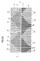
- FIG. 1 shown arrangement, in addition to the above-described filtering of the cosine signal only a limited filtering of the sine signal with the phases 90 ° and 270 ° possible.
- FIG. 2 illustrated further development of the arrangement FIG. 1 intended.
- FIG. 2 are used in each case two grating periods (d), ie consisting of 32 detector elements E detector blocks alternately for the filtering of the cosine signal and for the filtering of the sine signal.
- the blocks used for filtering the cosine signal in each case contain those detector groups G1, G3 which generate output signals with a phase of 0 ° or 180 °.
- the detector blocks used to filter the sine signal comprise detector groups G2, G4, which respectively generate output signals with a phase of 90 ° and 270 °, respectively.
- each of the detector blocks G1 or G3 or G2 or G4 which are used for filtering the cosine signal or in the detector blocks used to filter the sine signal, are alternately subjected to a distance filter and a width filter. So is in FIG. 2 in the first detector block, the width of the detector groups G1, which produce output signals with a phase of 0 °, eight detector elements each. The width of the two detector groups G3, which respectively produce output signals with a phase of 180 °, is in contrast once eleven detector elements and once five detector elements.
- those detector groups G1 producing output signals having a phase of 0 ° are subjected to a distance filter at a constant width and those detector groups G3 producing output signals having a phase of 180 ° are subjected to a width filter.
- the third detector block which in turn comprises detector groups G1, G3, which produce output signals with a phase of 0 ° or 180 °, the situation is exactly the opposite.
- Those detector groups G3, which produce an output signal with a phase of 180 ° have there a constant width of eight detector elements, while the other detector groups G1 have a width of ten or six detector elements.
- the second and fourth detector block each containing detector groups G2, G4, which produce output signals with a phase of 90 ° and 270 °, respectively.
- the detector groups G2, which produce output signals with a phase of 90 ° each have a constant width of eight detector elements, while the two other detector groups G4 in one case a width of ten detector elements and in the other case a width of six Have detector elements.
- the fourth detector block the situation is again reversed: here the detector groups G4, the output signals with a phase of 270 ° produce a constant width of eight detector elements, and the other detector groups G2 have in one case a width of eleven detector elements and in the other case a width of five detector elements.
- Both the detector blocks that filter the cosine signal and the detector blocks that filter the sine signal vary the distance between the detector groups that are subjected to a distance filter.
- FIG. 2 illustrated detector blocks it is partly eighteen and partly nineteen detector elements.
- the width filter formed in a part of the detector blocks by the combination of detector groups of width eleven detector elements with detector groups of five width detector elements, and in other detector blocks by combination of detector blocks of width ten detector elements with detector width six widths detector elements. This is done for the reasons given above to minimize the overall error of the arrangement to optimize the filtering effect.
- FIG. 2 Overall, it is characterized by an improved symmetry both with regard to the filtering of the cosine signal on the one hand and the filtering of the sine signal on the other hand, and with regard to the use of the wide filter on the one hand and the distance filter on the other hand in the individual detector blocks. This improves in particular the insensitivity of the device to contamination.
- illustrated embodiment and arrangement of the detector groups G1, G2, G3 and G4 allows a similar filtering of both the sine and the cosine signal; however, this arrangement suffers from the loss of the single field character of the sample, ie, the extraction of all four phases from one signal period.
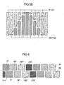
- FIG. 3 a doubling of the Abtastspur provided so that the detection device D comprises two perpendicular to their extension direction R (measuring direction) juxtaposed traces S1, S2, wherein in each of the two tracks in each case detector blocks with detector groups G1, G3 for filtering the cosine signal and detector blocks are arranged with detector groups G2, G4 for filtering the sine signal.
- Detector blocks arranged next to one another in each case transverse to the direction of extension R serve to filter different signals, ie filter block in the track S1 (consisting of detector groups G1, G3 with output signals of the phase 0 ° and 180 °) is arranged next to a filtering of the cosine signal the other track S2 each have a detector block for filtering the sine signal (ie consisting of the detector groups G2 and G4, which produce output signals of the phase 90 ° and 270 °), and vice versa.
- filter block in the track S1 consisting of detector groups G1, G3 with output signals of the phase 0 ° and 180 °
- the other track S2 each have a detector block for filtering the sine signal (ie consisting of the detector groups G2 and G4, which produce output signals of the phase 90 ° and 270 °), and vice versa.
- a base unit which serves to filter both the cosine signal and the sine signal and which includes both width and distance filters along the extension direction R only has an extension of 32 detector elements (corresponding to two grating constants d of the measurement graduation to be scanned) ) on.
- Another advantage of in FIG. 3 shown arrangement with two side by side, parallel to each other along the extension direction R extending tracks S1, S2 is thus in the reduction of the scan length.
- the gaps L between adjacent detector elements E correspond to unused detector elements of the detection device in each case during the formation of the detector groups G1, G2, G3 and G4.
- the corresponding, unused detector elements are not connected to the evaluation unit, and therefore are in particular not interconnected with the further detector elements to form detector groups.
- these may also be gaps L which, for technical reasons, do not contain any detector elements anyway.
- the original, finest structure with the smallest pitch g f can already be embodied in a plurality of tracks in order to filter out the coarser ones Track with a larger grid to achieve an additional degree of freedom for the optimal distribution of the detector groups, compare the DE 100 20 575 A1 ,
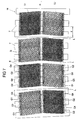
- FIG. 4 shows a detection device D, which has two transversely to the extension direction R (measuring direction) juxtaposed tracks S1, S2.
- Each of the two tracks S1, S2 extends along the measuring direction R.
- the first track S1 is thereby formed by detector groups G1, G3, the output signals with a phase of 0 ° or 180 ° generate
- the second track S2 is formed by Detector groups G2, G4, the output signals with a phase of 90 ° or 270 ° generate.
- FIG. 4 In this case, the ideal arrangement of the detector groups G1, G2, G3, G4 is shown. According to the above with reference to the FIGS. 1 to 3 described embodiments, there is also the problem that from real detector elements (in FIG. 4 for the sake of clarity not shown) detector groups do not have exactly the specified by the generating filter functions position and extent. Accordingly, by suitable arrangement of detector groups, which each have deviations from the ideal detector group, a minimization, if possible elimination, of the total error must take place. This is done on the basis of the same principles explained above for the errors f 1 and f 2 in the filtering of harmonics by a distance and a width filter.
- the individual detector groups are characterized by a characteristic variation of their extent transverse to the extension direction R.
- a filter function of the detection device designed for scanning the coarser measurement graduation can also be effected by suitable interconnection of the individual detector elements along a direction Q transverse to the extension or extension Measuring direction of the detection device D can be achieved. That is, based on the underlying measurement division M (cf. FIG. 7 This is of course, as already mentioned, only possible if along the transverse direction Q (perpendicular to the extension direction R) a sufficient number of detector elements is arranged side by side.
- the corresponding tracks from the outset have detector elements whose extent along the transverse direction Q varies, then only along the extension direction R arranged side by side detector elements of different dimensions in the transverse direction Q must be interconnected to form the desired detector groups.
- detector areas each having different extension along the transverse direction Q, are formed by detector elements which have a priori different expansion along the transverse direction Q, or by the interconnection of smaller detector elements along the transverse direction Q, these detector areas must be connected in the extension direction R to form detector groups.
- FIG. 5a shows such an arrangement with two juxtaposed tracks S1, S2, wherein the one track S1 detector groups G1, G3, which produce output signals with a phase of 0 ° or 180 °, and the other, adjacent track S2 includes detector groups G2, G4 , which produce output signals with a phase of 90 ° or 270 °.
- k takes an integer value between -N and N).
- FIG. 5b shows by way of example as an ideal filter function represented by a solid line on the basis of a sine or cosine function can be approximated by interconnection of detector elements transversely to the direction of extension of the detection device, and for example for detector groups G1, G3 of the phase 0 ° or 180 °.
- the individual detector regions the extent of which varies along a transverse direction Q perpendicular to the direction of extent R, can be achieved by suitable interconnection along the transverse direction Q of adjacent detector elements or on the other hand by the individual detector elements eventually extending along the extension direction R to detector groups G1 , G2, G3, G4, from the outset have a different extent along the transverse direction Q.
- Ax is generally not an integer multiple of g, f, so that here the actual offset distance .DELTA.x of detector groups, which can be so formed f only by an integer multiple of g, from the ideal value for Ax differs.
- a minimization of the total error is to be made, as explained above on the example of the width filter and the distance filter.
Landscapes
- Physics & Mathematics (AREA)
- General Physics & Mathematics (AREA)
- Optical Transform (AREA)
- Body Structure For Vehicles (AREA)
- Analysing Materials By The Use Of Radiation (AREA)
- Vehicle Body Suspensions (AREA)
- Transmission And Conversion Of Sensor Element Output (AREA)
- Length Measuring Devices With Unspecified Measuring Means (AREA)
Claims (12)
- Dispositif de mesure de position, avec- une graduation de mesure (M) étendue le long d'une direction de mesure,- une unité de balayage pour le balayage de la graduation de mesure (M) et- un dispositif de détection (D) de l'unité de balayage, comprenant une multitude d'éléments de détecteur (E) disposés périodiquement les uns derrière les autres le long d'une direction d'extension (R), produisant des signaux de sortie susceptibles d'être envoyés à une unité d'évaluation lors du balayage de la graduation de mesure (M),dans lequel les éléments de détecteur (E) voisins sont connectés de telle manière entre eux en formant un groupe de détecteurs (G1, G2, G3, G4), que leurs signaux de sortie sont réunis et peuvent être envoyés à l'unité d'évaluation en tant que signal unique,
caractérisé en ce que
les éléments de détecteur (E) sont rassemblés de telle manière en groupes de détecteurs (G1, G2, G3, G4) et les groupes de détecteurs (G1, G2, G3, G4) sont disposés de telle manière les uns derrière les autres le long de la direction d'extension (R), qu'au moins une onde harmonique est éliminée des signaux de sortie, ce pour quoi, soit- pour l'élimination des ondes harmoniques, l'espacement entre les groupes de détecteurs (G1, G2, G3, G4) varie le long de la direction d'extension (R), et l'espacement Δx entre les groupes de détecteurs (G1, G2, G3, G4) est déterminé selon la formule
avec de préférence d = i * gf, d indiquant la constante de grille de la graduation de mesure à balayer et gf indiquant la constante de grille de la disposition périodique des différents éléments de détecteur (E), n étant l'onde harmonique à filtrer, m un nombre entier et i un nombre naturel,
soit- pour l'élimination des ondes harmoniques, l'extension des groupes de détecteurs (G1, G2, G3, G4) varie le long de la direction d'extension (R), et l'extension Δb des groupes de détecteurs (G1, G2, G3, G4) le long de la direction d'extension (R) est déterminée par la formule
avec de préférence d = i * gf, où i et k sont des nombres naturels, d désignant la constante de grille de la graduation de mesure (M) à balayer et gf la constant de grille de la disposition périodique des différents éléments de détecteur (E), et n indiquant l'onde harmonique à filtrer,
soit- la disposition des groupes de détecteurs (G1, G2, G3, G4) le long de la direction d'extension (R) est définie selon une fonction arc sinus, et la position x des groupes de détecteurs (G1, G2, G3, G4) est décrite par la fonction
avec de préférence d = i * gf, où i et N sont des nombres naturels et k est un nombre entier inférieur ou égal à N (k = -N ... N), et d désigne la constante de grille de la graduation de mesure (M) à balayer, et gf la constante de grille de la disposition périodique des différents éléments de détecteur (E),
soit- l'extension des groupes de détecteurs (G1, G2, G3, G4) varie perpendiculairement à la direction d'extension (R), et l'extension des groupes de détecteurs (G1, G2, G3, G4) varie perpendiculairement à la direction d'extension (R) selon une fonction cosinus ou une fonction sinus,
soit- la disposition des groupes de détecteurs (G1, G2, G3, G4) le long de la direction d'extension (R) est déterminée par une combinaison d'une première fonction de filtre, selon laquelle l'espacement des groupes de détecteurs (G1, G2, G3, G4) varie dans la direction d'extension (R), avec une deuxième fonction de filtre, selon laquelle l'extension des groupes de détecteurs (G1, G2, G3, G4) varie dans la direction d'extension (R). - Dispositif de mesure de position selon la revendication 1, caractérisé en ce que plusieurs groupes de détecteurs (G1, G2, G3, G4) espacés les uns des autres dans la direction d'extension (R) sont à chaque fois connectés de telle façon les uns aux autres, que leurs signaux de sortie sont réunis et envoyés à l'unité d'évaluation en tant que signal unique.
- Dispositif de mesure de position selon la revendication 2, caractérisé en ce que les groupes de détecteurs (G1, G2, G3, G4) connectés entre eux produisent chacun des signaux de sortie d'une phase (0°, 90°, 180°, 270°).
- Dispositif de mesure de position selon la revendication 3, caractérisé en ce que le nombre d'éléments de détecteur (E) formant des groupes de détecteurs (G1, G2, G3, G4) d'une phase (0°, 90°, 180°, 270°) varie le long de la direction d'extension (R) du dispositif de détection (D).
- Dispositif de mesure de position selon la revendication 1, caractérisé en ce que la forme des différents éléments de détecteur (E) connectés en un groupe de détecteurs (G1, G2, G3, G4) est choisie de manière à produire un filtrage d'au moins une autre onde harmonique, résultant du balayage d'une graduation de mesure (M) avec une autre période de division (df).
- Dispositif de mesure de position selon l'une des revendications 1 à 5, caractérisé en ce que les groupes de détecteurs (G1, G2, G3, G4) sont disposés le long d'au moins deux pistes (S1, S2) disposées côte à côte, perpendiculairement à la direction d'extension (R).
- Dispositif de mesure de position selon la revendication 1, caractérisé en ce que la disposition des groupes de détecteurs (G1, G2, G3, G4) le long de la direction d'extension (R) est déterminée par au moins une fonction de filtre définissant, pour chaque élément de détecteur (E), avec quel élément de détecteur (E) voisin il est connecté.
- Dispositif de mesure de position selon la revendication 7, caractérisé en ce que la disposition de groupes de détecteurs (G1, G2, G3, G4) le long de la direction d'extension (R) est déterminée par la combinaison d'au moins deux fonctions de filtre, qui se rapportent à différents groupes de détecteurs et/ou à différentes caractéristiques d'un groupe de détecteurs.
- Dispositif de mesure de position selon la revendication 8, caractérisé en ce que le disposition des groupes de détecteurs (G1, G2, G3, G4) le long de la direction d'extension (R) est déterminée par la combinaison d'au moins deux fonctions de filtre complémentaires, qui se rapportent à différents groupes de détecteurs et/ou à différentes caractéristiques d'un groupe de détecteurs.
- Dispositif de mesure de position selon la revendication 6, caractérisé en ce que les groupes de détecteurs (G1, G2, G3, G4) des différentes phases (0°, 90°, 180°, 270°) dans les différentes pistes (S1, S2) sont disposés en décalage d'un certain espacement de décalage (Δx) les uns par rapport aux autres le long de la direction d'extension (R).
- Dispositif de mesure de position selon la revendication 10, caractérisé en ce que l'espacement de décalage (Δx) des groupes de détecteurs (G1, G2, G3, G4) d'une phase (0°, 90°, 180°, 270°) résulte de

avec de préférence d = i * gf, où d indique la constante de grille de la graduation de mesure (M) à balayer, et gf la constante de grille de la disposition périodique des différents éléments de détecteur (E), n étant l'onde harmonique à filtrer, m un nombre entier et i un nombre naturel. - Dispositif de mesure de position selon la revendication 11, caractérisé en ce que la disposition des groupes de détecteurs (G1, G2, G3, G4) dans la direction d'extension (R) est déterminée par la combinaison de deux fonctions arc sinus.
Applications Claiming Priority (2)
| Application Number | Priority Date | Filing Date | Title |
|---|---|---|---|
| DE10338991 | 2003-08-18 | ||
| DE10338991A DE10338991A1 (de) | 2003-08-18 | 2003-08-18 | Positionsmesseinrichtung |
Publications (2)
| Publication Number | Publication Date |
|---|---|
| EP1515123A1 EP1515123A1 (fr) | 2005-03-16 |
| EP1515123B1 true EP1515123B1 (fr) | 2010-01-27 |
Family
ID=34129600
Family Applications (1)
| Application Number | Title | Priority Date | Filing Date |
|---|---|---|---|
| EP04017269A Expired - Lifetime EP1515123B1 (fr) | 2003-08-18 | 2004-07-22 | Détecteur de position |
Country Status (6)
| Country | Link |
|---|---|
| US (1) | US7084390B2 (fr) |
| EP (1) | EP1515123B1 (fr) |
| JP (1) | JP4746294B2 (fr) |
| CN (1) | CN100343624C (fr) |
| AT (1) | ATE456785T1 (fr) |
| DE (2) | DE10338991A1 (fr) |
Families Citing this family (7)
| Publication number | Priority date | Publication date | Assignee | Title |
|---|---|---|---|---|
| US20070024865A1 (en) * | 2005-07-26 | 2007-02-01 | Mitchell Donald K | Optical encoder having slanted optical detector elements for harmonic suppression |
| DE102010002902A1 (de) * | 2010-03-16 | 2011-09-22 | Dr. Johannes Heidenhain Gmbh | Abtasteinheit für eine optische Positionsmesseinrichtung |
| JP5574899B2 (ja) * | 2010-09-24 | 2014-08-20 | キヤノン株式会社 | ロータリーエンコーダ及びこれを備えた光学機器 |
| EP3255384B1 (fr) * | 2016-06-07 | 2018-11-28 | Dr. Johannes Heidenhain GmbH | Echelle et dispositif de mesure de position |
| US10168189B1 (en) * | 2017-06-29 | 2019-01-01 | Mitutoyo Corporation | Contamination and defect resistant optical encoder configuration for providing displacement signal having a plurality of spatial phase detectors arranged in a spatial phase sequence along a direction transverse to the measuring axis |
| DE102018202556A1 (de) * | 2018-02-20 | 2019-08-22 | Dr. Johannes Heidenhain Gmbh | Optische Positionsmesseinrichtung |
| CN108444506B (zh) * | 2018-05-31 | 2024-03-22 | 苏州汇川技术有限公司 | 编码器码盘、绝对值编码器、位置获取方法及系统 |
Family Cites Families (33)
| Publication number | Priority date | Publication date | Assignee | Title |
|---|---|---|---|---|
| JPS629218A (ja) * | 1985-07-08 | 1987-01-17 | Hitachi Metals Ltd | 磁気式回転検出器 |
| DE3616144A1 (de) * | 1986-05-14 | 1987-11-19 | Heidenhain Gmbh Dr Johannes | Fotoelektrische messeinrichtung |
| JPH075954B2 (ja) * | 1987-12-10 | 1995-01-25 | 九築工業株式会社 | 転炉ライニング築造装置 |
| JPH02193003A (ja) * | 1989-01-23 | 1990-07-30 | Fujitsu Ltd | リニアパルスモータの位置センサ機構 |
| JPH03128418A (ja) * | 1989-07-20 | 1991-05-31 | Yokogawa Electric Corp | 光学式エンコーダ |
| JP2670193B2 (ja) * | 1991-02-25 | 1997-10-29 | オークマ株式会社 | 位置検出器 |
| EP0541827B1 (fr) * | 1991-11-04 | 1995-04-12 | Dr. Johannes Heidenhain GmbH | Appareil pour produire des signaux périodiques, avec un absence d'harmoniques supérieurs |
| JPH0626885A (ja) * | 1992-07-07 | 1994-02-04 | Tamagawa Seiki Co Ltd | 光学式エンコーダにおけるエンコーダ信号の歪除去方法 |
| EP0620416B1 (fr) * | 1993-04-10 | 1997-01-02 | Dr. Johannes Heidenhain GmbH | Système de mesure magnétique |
| EP0645607B1 (fr) * | 1993-08-07 | 1997-06-04 | Dr. Johannes Heidenhain GmbH | Dispositif de production de signaux périodiques sans harmonie |
| CH690971A5 (de) * | 1994-02-25 | 2001-03-15 | Hera Rotterdam Bv | Verfahren zur Messung und Verwertung einer Verschiebung eines Abtastkopfes gegenüber einer Massverkörperung und optischer Messgeber zur Durchführung dieses Verfahrens. |
| JP2695623B2 (ja) * | 1994-11-25 | 1998-01-14 | 株式会社ミツトヨ | 光学式エンコーダ |
| JP3327718B2 (ja) * | 1995-01-23 | 2002-09-24 | オークマ株式会社 | 光学式エンコーダ |
| DE19508700C1 (de) * | 1995-03-02 | 1996-08-14 | Huebner Elektromasch Ag | Vorrichtung zum Gewinnen weitgehend oberwellenfreier periodischer Signale |
| DE19511068A1 (de) * | 1995-03-25 | 1996-09-26 | Heidenhain Gmbh Dr Johannes | Lichtelektrische Positionsmeßeinrichtung |
| JP3215289B2 (ja) * | 1995-04-17 | 2001-10-02 | オークマ株式会社 | スケール及びエンコーダ |
| EP0750179B1 (fr) * | 1995-06-22 | 2000-04-26 | Dr. Johannes Heidenhain GmbH | Dispositif pour mesurer une position |
| DE19532246A1 (de) * | 1995-09-01 | 1997-03-06 | Heidenhain Gmbh Dr Johannes | Vorrichtung zur Filterung von Oberwellen-Signalanteilen |
| JPH09196705A (ja) * | 1996-01-23 | 1997-07-31 | Mitsutoyo Corp | 変位測定装置 |
| JP3209914B2 (ja) * | 1996-03-19 | 2001-09-17 | オークマ株式会社 | 光学式エンコーダ |
| US6094307A (en) * | 1996-05-17 | 2000-07-25 | Okuma Corporation | Optical grating and encoder |
| DE19628602A1 (de) * | 1996-07-16 | 1998-01-22 | Heidenhain Gmbh Dr Johannes | Vorrichtung zur Filterung von Oberwellen-Signalanteilen |
| JP3278361B2 (ja) * | 1996-10-25 | 2002-04-30 | オークマ株式会社 | 光学式エンコーダ |
| DE59806597D1 (de) * | 1997-08-07 | 2003-01-23 | Heidenhain Gmbh Dr Johannes | Abtasteinheit für eine optische Positionsmesseinrichtung |
| JPH11223505A (ja) * | 1997-12-03 | 1999-08-17 | Mitsutoyo Corp | 誘導型位置測定装置 |
| AUPP777898A0 (en) * | 1998-12-17 | 1999-01-21 | Bishop Innovation Pty Limited | Position sensor |
| DE19962278A1 (de) * | 1999-12-23 | 2001-08-02 | Heidenhain Gmbh Dr Johannes | Positionsmeßeinrichtung |
| DE10020575A1 (de) * | 2000-04-28 | 2001-10-31 | Heidenhain Gmbh Dr Johannes | Abtasteinheit für eine optische Positionsmesseinrichtung |
| JP3930227B2 (ja) | 2000-06-14 | 2007-06-13 | ペンタックス株式会社 | 磁気式エンコーダおよび磁気式エンコーダを搭載した測量機 |
| JP3589621B2 (ja) * | 2000-07-03 | 2004-11-17 | 株式会社ミツトヨ | 光電式エンコーダ及びそのセンサヘッドの製造方法 |
| CA2458964A1 (fr) * | 2001-08-30 | 2003-03-13 | William G. Thorburn | Reseau de photodetecteurs avec suppression des harmoniques |
| US6794638B2 (en) * | 2001-09-13 | 2004-09-21 | Mitutoyo Corporation | Photoelectric encoder having improved light-emitting and photoreceptive sections |
| US6727493B2 (en) * | 2001-11-06 | 2004-04-27 | Renco Incoders, Inc. | Multiple resolution photodiode sensor array for an optical encoder |
-
2003
- 2003-08-18 DE DE10338991A patent/DE10338991A1/de not_active Withdrawn
-
2004
- 2004-07-22 EP EP04017269A patent/EP1515123B1/fr not_active Expired - Lifetime
- 2004-07-22 DE DE502004010699T patent/DE502004010699D1/de not_active Expired - Lifetime
- 2004-07-22 AT AT04017269T patent/ATE456785T1/de not_active IP Right Cessation
- 2004-08-18 CN CNB200410056762XA patent/CN100343624C/zh not_active Expired - Fee Related
- 2004-08-18 JP JP2004238243A patent/JP4746294B2/ja not_active Expired - Fee Related
- 2004-08-18 US US10/921,452 patent/US7084390B2/en not_active Expired - Lifetime
Also Published As
| Publication number | Publication date |
|---|---|
| EP1515123A1 (fr) | 2005-03-16 |
| JP2005062194A (ja) | 2005-03-10 |
| DE502004010699D1 (de) | 2010-03-18 |
| DE10338991A1 (de) | 2005-03-17 |
| US7084390B2 (en) | 2006-08-01 |
| JP4746294B2 (ja) | 2011-08-10 |
| CN100343624C (zh) | 2007-10-17 |
| ATE456785T1 (de) | 2010-02-15 |
| CN1584492A (zh) | 2005-02-23 |
| US20050051716A1 (en) | 2005-03-10 |
Similar Documents
| Publication | Publication Date | Title |
|---|---|---|
| EP1111345B1 (fr) | Dispositif de mesure de position avec une piste incrementielle avec deux graduations de période differente | |
| DE69521270T2 (de) | Optischer Kodierer | |
| DE68926355T2 (de) | Kapazitives System zum Positionsgeben | |
| DE3784360T2 (de) | Kapazitanztransduktor fuer positionsmessung. | |
| DE69227009T2 (de) | Opto-elektronischer Skalenleseapparat | |
| DE112006001970T5 (de) | Optischer Kodierer mit geneigten optischen Detektorelementen zur Unterdrückung von Harmonischen | |
| DE3417176A1 (de) | Photoelektrische messeinrichtung | |
| EP0102472A1 (fr) | Dispositif pour mesurer la longueur et l'angle | |
| DE102018210742B4 (de) | Verschmutzungs- und defektbeständige optische Codiererkonfiguration zum Bereitstellen von Verschiebungssignalen | |
| EP0624778A1 (fr) | Dispositif de mesure de position | |
| EP1524503B1 (fr) | Codeur optique | |
| DE102005036180B4 (de) | Optische Positionsmesseinrichtung | |
| EP1173726B1 (fr) | Dispositif optique de mesure de position | |
| EP1515123B1 (fr) | Détecteur de position | |
| EP0482224A1 (fr) | Dispositif interférentiel de mesure pour au moins une direction de mesure | |
| EP0669519A2 (fr) | Dispositif de mesure de positions | |
| EP0747674B1 (fr) | Dispositif photo-électrique de mesure de positions | |
| EP2869031B1 (fr) | Dispositif de mesure de position | |
| DE102018210707A1 (de) | Verschmutzungs- und defektbeständige optische Codiererkonfiguration zum Bereitstellen von Verschiebungssignalen | |
| DE102018210749A1 (de) | Verschmutzungs- und defektbeständige optische Codiererkonfiguration zum Bereitstellen von Verschiebungssignalen | |
| EP0819915B1 (fr) | Dispositif de filtrage des composants harmoniques d'un signal | |
| EP0608758A1 (fr) | Dispositif de mesure pour plusieurs coördonnées | |
| EP0541829B1 (fr) | Dispositif pour générer des signaux périodiques sans harmoniques | |
| DE3509102A1 (de) | Messeinrichtung | |
| EP0547270B1 (fr) | Appareil photoélectrique pour générer des signaux périodiques exempte d'harmoniques |
Legal Events
| Date | Code | Title | Description |
|---|---|---|---|
| PUAI | Public reference made under article 153(3) epc to a published international application that has entered the european phase |
Free format text: ORIGINAL CODE: 0009012 |
|
| AK | Designated contracting states |
Kind code of ref document: A1 Designated state(s): AT BE BG CH CY CZ DE DK EE ES FI FR GB GR HU IE IT LI LU MC NL PL PT RO SE SI SK TR |
|
| AX | Request for extension of the european patent |
Extension state: AL HR LT LV MK |
|
| 17P | Request for examination filed |
Effective date: 20050916 |
|
| AKX | Designation fees paid |
Designated state(s): AT BE BG CH CY CZ DE DK EE ES FI FR GB GR HU IE IT LI LU MC NL PL PT RO SE SI SK TR |
|
| 17Q | First examination report despatched |
Effective date: 20071213 |
|
| GRAP | Despatch of communication of intention to grant a patent |
Free format text: ORIGINAL CODE: EPIDOSNIGR1 |
|
| GRAS | Grant fee paid |
Free format text: ORIGINAL CODE: EPIDOSNIGR3 |
|
| GRAA | (expected) grant |
Free format text: ORIGINAL CODE: 0009210 |
|
| AK | Designated contracting states |
Kind code of ref document: B1 Designated state(s): AT BE BG CH CY CZ DE DK EE ES FI FR GB GR HU IE IT LI LU MC NL PL PT RO SE SI SK TR |
|
| REG | Reference to a national code |
Ref country code: GB Ref legal event code: FG4D Free format text: NOT ENGLISH |
|
| REG | Reference to a national code |
Ref country code: CH Ref legal event code: EP |
|
| REG | Reference to a national code |
Ref country code: CH Ref legal event code: NV Representative=s name: ICB INGENIEURS CONSEILS EN BREVETS SA |
|
| REG | Reference to a national code |
Ref country code: IE Ref legal event code: FG4D |
|
| REF | Corresponds to: |
Ref document number: 502004010699 Country of ref document: DE Date of ref document: 20100318 Kind code of ref document: P |
|
| REG | Reference to a national code |
Ref country code: NL Ref legal event code: VDEP Effective date: 20100127 |
|
| PG25 | Lapsed in a contracting state [announced via postgrant information from national office to epo] |
Ref country code: ES Free format text: LAPSE BECAUSE OF FAILURE TO SUBMIT A TRANSLATION OF THE DESCRIPTION OR TO PAY THE FEE WITHIN THE PRESCRIBED TIME-LIMIT Effective date: 20100508 Ref country code: PT Free format text: LAPSE BECAUSE OF FAILURE TO SUBMIT A TRANSLATION OF THE DESCRIPTION OR TO PAY THE FEE WITHIN THE PRESCRIBED TIME-LIMIT Effective date: 20100527 Ref country code: NL Free format text: LAPSE BECAUSE OF FAILURE TO SUBMIT A TRANSLATION OF THE DESCRIPTION OR TO PAY THE FEE WITHIN THE PRESCRIBED TIME-LIMIT Effective date: 20100127 |
|
| REG | Reference to a national code |
Ref country code: IE Ref legal event code: FD4D |
|
| PG25 | Lapsed in a contracting state [announced via postgrant information from national office to epo] |
Ref country code: SI Free format text: LAPSE BECAUSE OF FAILURE TO SUBMIT A TRANSLATION OF THE DESCRIPTION OR TO PAY THE FEE WITHIN THE PRESCRIBED TIME-LIMIT Effective date: 20100127 Ref country code: FI Free format text: LAPSE BECAUSE OF FAILURE TO SUBMIT A TRANSLATION OF THE DESCRIPTION OR TO PAY THE FEE WITHIN THE PRESCRIBED TIME-LIMIT Effective date: 20100127 Ref country code: PL Free format text: LAPSE BECAUSE OF FAILURE TO SUBMIT A TRANSLATION OF THE DESCRIPTION OR TO PAY THE FEE WITHIN THE PRESCRIBED TIME-LIMIT Effective date: 20100127 |
|
| PG25 | Lapsed in a contracting state [announced via postgrant information from national office to epo] |
Ref country code: SE Free format text: LAPSE BECAUSE OF FAILURE TO SUBMIT A TRANSLATION OF THE DESCRIPTION OR TO PAY THE FEE WITHIN THE PRESCRIBED TIME-LIMIT Effective date: 20100127 Ref country code: RO Free format text: LAPSE BECAUSE OF FAILURE TO SUBMIT A TRANSLATION OF THE DESCRIPTION OR TO PAY THE FEE WITHIN THE PRESCRIBED TIME-LIMIT Effective date: 20100127 Ref country code: IE Free format text: LAPSE BECAUSE OF FAILURE TO SUBMIT A TRANSLATION OF THE DESCRIPTION OR TO PAY THE FEE WITHIN THE PRESCRIBED TIME-LIMIT Effective date: 20100127 Ref country code: CY Free format text: LAPSE BECAUSE OF FAILURE TO SUBMIT A TRANSLATION OF THE DESCRIPTION OR TO PAY THE FEE WITHIN THE PRESCRIBED TIME-LIMIT Effective date: 20100127 Ref country code: EE Free format text: LAPSE BECAUSE OF FAILURE TO SUBMIT A TRANSLATION OF THE DESCRIPTION OR TO PAY THE FEE WITHIN THE PRESCRIBED TIME-LIMIT Effective date: 20100127 Ref country code: GR Free format text: LAPSE BECAUSE OF FAILURE TO SUBMIT A TRANSLATION OF THE DESCRIPTION OR TO PAY THE FEE WITHIN THE PRESCRIBED TIME-LIMIT Effective date: 20100428 |
|
| PG25 | Lapsed in a contracting state [announced via postgrant information from national office to epo] |
Ref country code: SK Free format text: LAPSE BECAUSE OF FAILURE TO SUBMIT A TRANSLATION OF THE DESCRIPTION OR TO PAY THE FEE WITHIN THE PRESCRIBED TIME-LIMIT Effective date: 20100127 Ref country code: CZ Free format text: LAPSE BECAUSE OF FAILURE TO SUBMIT A TRANSLATION OF THE DESCRIPTION OR TO PAY THE FEE WITHIN THE PRESCRIBED TIME-LIMIT Effective date: 20100127 Ref country code: BG Free format text: LAPSE BECAUSE OF FAILURE TO SUBMIT A TRANSLATION OF THE DESCRIPTION OR TO PAY THE FEE WITHIN THE PRESCRIBED TIME-LIMIT Effective date: 20100427 |
|
| PLBE | No opposition filed within time limit |
Free format text: ORIGINAL CODE: 0009261 |
|
| STAA | Information on the status of an ep patent application or granted ep patent |
Free format text: STATUS: NO OPPOSITION FILED WITHIN TIME LIMIT |
|
| 26N | No opposition filed |
Effective date: 20101028 |
|
| BERE | Be: lapsed |
Owner name: DR. JOHANNES HEIDENHAIN G.M.B.H. Effective date: 20100731 |
|
| PG25 | Lapsed in a contracting state [announced via postgrant information from national office to epo] |
Ref country code: DK Free format text: LAPSE BECAUSE OF FAILURE TO SUBMIT A TRANSLATION OF THE DESCRIPTION OR TO PAY THE FEE WITHIN THE PRESCRIBED TIME-LIMIT Effective date: 20100127 |
|
| PG25 | Lapsed in a contracting state [announced via postgrant information from national office to epo] |
Ref country code: MC Free format text: LAPSE BECAUSE OF NON-PAYMENT OF DUE FEES Effective date: 20100731 |
|
| REG | Reference to a national code |
Ref country code: FR Ref legal event code: ST Effective date: 20110331 |
|
| PG25 | Lapsed in a contracting state [announced via postgrant information from national office to epo] |
Ref country code: FR Free format text: LAPSE BECAUSE OF NON-PAYMENT OF DUE FEES Effective date: 20100802 |
|
| PG25 | Lapsed in a contracting state [announced via postgrant information from national office to epo] |
Ref country code: BE Free format text: LAPSE BECAUSE OF NON-PAYMENT OF DUE FEES Effective date: 20100731 |
|
| PG25 | Lapsed in a contracting state [announced via postgrant information from national office to epo] |
Ref country code: AT Free format text: LAPSE BECAUSE OF NON-PAYMENT OF DUE FEES Effective date: 20100722 |
|
| PG25 | Lapsed in a contracting state [announced via postgrant information from national office to epo] |
Ref country code: HU Free format text: LAPSE BECAUSE OF FAILURE TO SUBMIT A TRANSLATION OF THE DESCRIPTION OR TO PAY THE FEE WITHIN THE PRESCRIBED TIME-LIMIT Effective date: 20100728 Ref country code: LU Free format text: LAPSE BECAUSE OF NON-PAYMENT OF DUE FEES Effective date: 20100722 |
|
| PG25 | Lapsed in a contracting state [announced via postgrant information from national office to epo] |
Ref country code: TR Free format text: LAPSE BECAUSE OF FAILURE TO SUBMIT A TRANSLATION OF THE DESCRIPTION OR TO PAY THE FEE WITHIN THE PRESCRIBED TIME-LIMIT Effective date: 20100127 |
|
| PGFP | Annual fee paid to national office [announced via postgrant information from national office to epo] |
Ref country code: IT Payment date: 20170728 Year of fee payment: 14 Ref country code: CH Payment date: 20170719 Year of fee payment: 14 |
|
| REG | Reference to a national code |
Ref country code: CH Ref legal event code: PL |
|
| PG25 | Lapsed in a contracting state [announced via postgrant information from national office to epo] |
Ref country code: LI Free format text: LAPSE BECAUSE OF NON-PAYMENT OF DUE FEES Effective date: 20180731 Ref country code: CH Free format text: LAPSE BECAUSE OF NON-PAYMENT OF DUE FEES Effective date: 20180731 |
|
| PG25 | Lapsed in a contracting state [announced via postgrant information from national office to epo] |
Ref country code: IT Free format text: LAPSE BECAUSE OF NON-PAYMENT OF DUE FEES Effective date: 20180722 |
|
| PGFP | Annual fee paid to national office [announced via postgrant information from national office to epo] |
Ref country code: GB Payment date: 20200727 Year of fee payment: 17 |
|
| GBPC | Gb: european patent ceased through non-payment of renewal fee |
Effective date: 20210722 |
|
| PG25 | Lapsed in a contracting state [announced via postgrant information from national office to epo] |
Ref country code: GB Free format text: LAPSE BECAUSE OF NON-PAYMENT OF DUE FEES Effective date: 20210722 |
|
| PGFP | Annual fee paid to national office [announced via postgrant information from national office to epo] |
Ref country code: DE Payment date: 20220620 Year of fee payment: 19 |
|
| REG | Reference to a national code |
Ref country code: DE Ref legal event code: R119 Ref document number: 502004010699 Country of ref document: DE |
|
| PG25 | Lapsed in a contracting state [announced via postgrant information from national office to epo] |
Ref country code: DE Free format text: LAPSE BECAUSE OF NON-PAYMENT OF DUE FEES Effective date: 20240201 |