EP1515059B1 - Dispositif de fixation axiale d'un embrayage sur un joint rotatif - Google Patents
Dispositif de fixation axiale d'un embrayage sur un joint rotatif Download PDFInfo
- Publication number
- EP1515059B1 EP1515059B1 EP04013095A EP04013095A EP1515059B1 EP 1515059 B1 EP1515059 B1 EP 1515059B1 EP 04013095 A EP04013095 A EP 04013095A EP 04013095 A EP04013095 A EP 04013095A EP 1515059 B1 EP1515059 B1 EP 1515059B1
- Authority
- EP
- European Patent Office
- Prior art keywords
- clutch
- latching
- rotary joint
- motor vehicle
- circumference
- Prior art date
- Legal status (The legal status is an assumption and is not a legal conclusion. Google has not performed a legal analysis and makes no representation as to the accuracy of the status listed.)
- Expired - Fee Related
Links
Images

Classifications
-
- F—MECHANICAL ENGINEERING; LIGHTING; HEATING; WEAPONS; BLASTING
- F16—ENGINEERING ELEMENTS AND UNITS; GENERAL MEASURES FOR PRODUCING AND MAINTAINING EFFECTIVE FUNCTIONING OF MACHINES OR INSTALLATIONS; THERMAL INSULATION IN GENERAL
- F16D—COUPLINGS FOR TRANSMITTING ROTATION; CLUTCHES; BRAKES
- F16D25/00—Fluid-actuated clutches
- F16D25/06—Fluid-actuated clutches in which the fluid actuates a piston incorporated in, i.e. rotating with the clutch
- F16D25/062—Fluid-actuated clutches in which the fluid actuates a piston incorporated in, i.e. rotating with the clutch the clutch having friction surfaces
- F16D25/063—Fluid-actuated clutches in which the fluid actuates a piston incorporated in, i.e. rotating with the clutch the clutch having friction surfaces with clutch members exclusively moving axially
- F16D25/0635—Fluid-actuated clutches in which the fluid actuates a piston incorporated in, i.e. rotating with the clutch the clutch having friction surfaces with clutch members exclusively moving axially with flat friction surfaces, e.g. discs
- F16D25/0638—Fluid-actuated clutches in which the fluid actuates a piston incorporated in, i.e. rotating with the clutch the clutch having friction surfaces with clutch members exclusively moving axially with flat friction surfaces, e.g. discs with more than two discs, e.g. multiple lamellae
-
- F—MECHANICAL ENGINEERING; LIGHTING; HEATING; WEAPONS; BLASTING
- F16—ENGINEERING ELEMENTS AND UNITS; GENERAL MEASURES FOR PRODUCING AND MAINTAINING EFFECTIVE FUNCTIONING OF MACHINES OR INSTALLATIONS; THERMAL INSULATION IN GENERAL
- F16D—COUPLINGS FOR TRANSMITTING ROTATION; CLUTCHES; BRAKES
- F16D21/00—Systems comprising a plurality of actuated clutches
- F16D21/02—Systems comprising a plurality of actuated clutches for interconnecting three or more shafts or other transmission members in different ways
- F16D21/06—Systems comprising a plurality of actuated clutches for interconnecting three or more shafts or other transmission members in different ways at least two driving shafts or two driven shafts being concentric
-
- F—MECHANICAL ENGINEERING; LIGHTING; HEATING; WEAPONS; BLASTING
- F16—ENGINEERING ELEMENTS AND UNITS; GENERAL MEASURES FOR PRODUCING AND MAINTAINING EFFECTIVE FUNCTIONING OF MACHINES OR INSTALLATIONS; THERMAL INSULATION IN GENERAL
- F16D—COUPLINGS FOR TRANSMITTING ROTATION; CLUTCHES; BRAKES
- F16D25/00—Fluid-actuated clutches
- F16D25/10—Clutch systems with a plurality of fluid-actuated clutches
-
- F—MECHANICAL ENGINEERING; LIGHTING; HEATING; WEAPONS; BLASTING
- F16—ENGINEERING ELEMENTS AND UNITS; GENERAL MEASURES FOR PRODUCING AND MAINTAINING EFFECTIVE FUNCTIONING OF MACHINES OR INSTALLATIONS; THERMAL INSULATION IN GENERAL
- F16D—COUPLINGS FOR TRANSMITTING ROTATION; CLUTCHES; BRAKES
- F16D25/00—Fluid-actuated clutches
- F16D25/12—Details not specific to one of the before-mentioned types
-
- F—MECHANICAL ENGINEERING; LIGHTING; HEATING; WEAPONS; BLASTING
- F16—ENGINEERING ELEMENTS AND UNITS; GENERAL MEASURES FOR PRODUCING AND MAINTAINING EFFECTIVE FUNCTIONING OF MACHINES OR INSTALLATIONS; THERMAL INSULATION IN GENERAL
- F16D—COUPLINGS FOR TRANSMITTING ROTATION; CLUTCHES; BRAKES
- F16D21/00—Systems comprising a plurality of actuated clutches
- F16D21/02—Systems comprising a plurality of actuated clutches for interconnecting three or more shafts or other transmission members in different ways
- F16D21/06—Systems comprising a plurality of actuated clutches for interconnecting three or more shafts or other transmission members in different ways at least two driving shafts or two driven shafts being concentric
- F16D2021/0607—Double clutch with torque input plate in-between the two clutches, i.e. having a central input plate
-
- F—MECHANICAL ENGINEERING; LIGHTING; HEATING; WEAPONS; BLASTING
- F16—ENGINEERING ELEMENTS AND UNITS; GENERAL MEASURES FOR PRODUCING AND MAINTAINING EFFECTIVE FUNCTIONING OF MACHINES OR INSTALLATIONS; THERMAL INSULATION IN GENERAL
- F16D—COUPLINGS FOR TRANSMITTING ROTATION; CLUTCHES; BRAKES
- F16D21/00—Systems comprising a plurality of actuated clutches
- F16D21/02—Systems comprising a plurality of actuated clutches for interconnecting three or more shafts or other transmission members in different ways
- F16D21/06—Systems comprising a plurality of actuated clutches for interconnecting three or more shafts or other transmission members in different ways at least two driving shafts or two driven shafts being concentric
- F16D2021/0661—Hydraulically actuated multiple lamellae clutches
-
- F—MECHANICAL ENGINEERING; LIGHTING; HEATING; WEAPONS; BLASTING
- F16—ENGINEERING ELEMENTS AND UNITS; GENERAL MEASURES FOR PRODUCING AND MAINTAINING EFFECTIVE FUNCTIONING OF MACHINES OR INSTALLATIONS; THERMAL INSULATION IN GENERAL
- F16D—COUPLINGS FOR TRANSMITTING ROTATION; CLUTCHES; BRAKES
- F16D21/00—Systems comprising a plurality of actuated clutches
- F16D21/02—Systems comprising a plurality of actuated clutches for interconnecting three or more shafts or other transmission members in different ways
- F16D21/06—Systems comprising a plurality of actuated clutches for interconnecting three or more shafts or other transmission members in different ways at least two driving shafts or two driven shafts being concentric
- F16D2021/0692—Systems comprising a plurality of actuated clutches for interconnecting three or more shafts or other transmission members in different ways at least two driving shafts or two driven shafts being concentric with two clutches arranged axially without radial overlap
Definitions
- This further latching device may, for example, have a plurality of circumferentially distributed substantially radially projecting locking lugs, which are formed in a plurality of arranged on an inner circumference or on an outer circumference of the rotary feedthrough grooves, recesses or the like engageable.
- At least one slide bearing device can be provided for an adjacent component of the device. Separate insertion of plain bearings, bearings and / or contact surfaces is no longer required, which also offers advantages in terms of assembly.
- the first transmission input shaft (central or solid shaft 10) can be used for the operation of all odd gears (eg 1, 3, 5 %) and the second transmission input shaft (hollow shaft 9) for the operation of all even gears (eg. 2, 4, 6 ...) of the motor vehicle.
- the reverse gear could be assigned to both the first transmission input shaft (central or solid shaft 10), and the second transmission input shaft (solid shaft 9) of the transmission G.
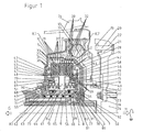
- the torsion or vibration damper 12 is formed in a manner known per se. On the input side, it has a primary element 14 in the form of a half-shell. On the output side, a secondary element consisting of a first half-shell 13 and a second half-shell 11, which also forms the coupling housing, is provided. Primary element 14 and Secondary element 13, 11 are coupled via a plurality of arranged on the outer circumference of the torsional vibration damper spring assemblies 12 in the rotational direction a torque transferable. As an example, a spring package is shown in the drawing.
- Each clutch K1, K2 comprises in each case an outer disk carrier 1, 2 and a common inner disk carrier 40.
- the outer disk carrier of the first clutch K1 is referred to below as the first outer disk carrier 1
- the outer disk carrier of the second clutch K2 is referred to below as the second outer disk carrier 2.
- the two outer disk carrier 1, 2 are formed in a half-shell-shaped, wherein the first outer disk carrier 1 surrounds the second outer disk carrier 2 in the axial direction outstanding.
- the inner disk carrier 40 has a substantially cylindrical shape and extends over the axially extending regions of the half-shell-shaped outer disk carrier 1, 2.
- the two outer disk carriers 1, 2 have internal toothings 5, 6, which serve for the axially displaceable but essentially non-rotatable guidance of friction disks 29, 30 having four respective external toothings 31, 32 in the present case.
- the latter are usually also referred to as outer plates 29, 30.
- the common inner disk carrier 40 outer teeth 41, 42 are arranged in which internal teeth having friction plates, the so-called inner plates 36, axially displaceable but rotatably guided.
- the two inner disk carrier sections are separated from each other by a common end plate 35.
- the outer friction disks / outer disks 29, 30, the inner friction disks / inner disks 33, 36 and the two pressure plates 34, 37 and the common end plate 35 engage each other in a manner known per se in a manner known per se to form a disk set 27, 28 associated with a clutch K1, K2 each other.
- the two disk sets 27, 28 with the corresponding friction plates 29, 30, 33, 34, 35, 36, 37 are thus arranged one behind the other on the common inner disk carrier 40 in the axial direction.
- the friction surfaces of all friction plates 29, 30, 33, 34, 35, 36, 37 are substantially the same size, so that the individual clutches K1, K2 have equivalent performance.
- the friction surfaces of the friction plates 29, 30, 33, 34, 35, 36, 37 have different sized outer and / or inner diameter.
- piston / cylinder units which serve to actuate the clutches K1, K2.
- everyone is Coupling K1, K2 associated with a hydraulically actuated actuating piston 43, 44.
- Each of these actuating piston 43, 44 can against one of the pressure plates 34, 37 force-transmitting and frictional engagement between the individual friction plates 29, 30, 33, 34, 35, 36, 37 generating and thus the respective clutch K1, K2 pressed pressed.
- Part of the clutch housing 11 is a cylinder 79 in to the cylinder 77 corresponding type. At the two cylinders 77, 79, the respective actuating piston 43, 44 are guided axially displaceable. Cylinder 77 and actuating piston 44 serve as a support and centering for the inner disk carrier 40th
- the actuators for the two clutches K1, K2 include, in addition to the aforementioned actuating piston 43, 44, by means of which the respective pressure plates 34, 37 of the disk packs 27, 28 can be moved in the direction of the common end plates 35, each a pressure piston 49, 50, a piston 51, 52, a compensating piston 55, 56 and a plurality of circumferentially arranged coil springs 53, 54.
- the respective actuating piston 43, 44 are supported against the respective pressure piston 49, 50 from which axially displaceably on the cylinders 79, 77 and Outer circumference of the clutch hub 61 are guided. Inwardly directed, the actuating pistons 43, 44 are supported against the pistons 51, 52.
- a separate rotary feedthrough 62 is provided, which surrounds the two transmission input shafts, the hollow shaft 9 and the solid shaft 10 coaxially and on which the clutch hub 61st is rotatably supported by means of a radial roller bearing 89 and a radial ball bearing 90.
- the rotary feedthrough 62 can be made in one piece or both axially and radially in several parts.
- the rotary feedthrough 62 is made in two parts. It consists of a jacket 83 and a bushing 84 enclosed by the latter.
- the cylinder jacket-shaped bushing 84 has, in its outer circumference, longitudinal grooves extending in the axial and / or radial direction of different lengths.
- the jacket 83 has corresponding to the arrangement of the aforementioned longitudinal grooves on four circumferentially extending grooves. These circumferential grooves are connected via radially extending openings, not shown here, with the corresponding longitudinal grooves.
- the coupling hub 61 has four substantially radially and partially axially inclined openings, which are hereinafter referred to as hydraulic fluid channels 63, 64, 65 and 66.
- hydraulic fluid channels 63, 64, 65 and 66 Via the grooves in the bushing 84, the openings and grooves in the shell 83 and the hydraulic fluid channels 63, 64, 65, 66 in the clutch hub 61, a supply of the volume formed by the pistons 43, 44, 49, 50, 55, 56 first hydraulic fluid actuating chamber 71, second hydraulic fluid actuating chamber 72, first hydraulic fluid compensation chamber 69, second hydraulic fluid compensation chamber 70, cooling fluid chamber 73) with hydraulic fluid.
- the hydraulic fluid compensation chambers 69, 70 and the cooling fluid chamber 73 are filled with hydraulic fluid via the two hydraulic fluid channels 64 and 65.
- the hydraulic fluid in the hydraulic fluid compensation chambers 69, 70 serves to generate a centrifugally induced hydraulic fluid back pressure, which counteracts the centrifugal pressure increase in the respective hydraulic fluid actuating chamber 71, 72.
- the hydraulic fluid in the cooling liquid space 73 is for cooling the friction plates 29 30 33, 34, 35, 36, 37 by radially extending (not shown here) openings in the inner disk carrier 40 to the friction plates 29, 30, 33, 34, 35, 36, 37 out ,
- the drive train components described in detail above are connected together as follows.
- the crankshaft 24 is bolted to the inner periphery of the flywheel 21 (screw 26, bore 23).
- the outer circumference of the flywheel 21 is riveted to the outer periphery of the bending / tumble disc 18 (outer edge bore 19, rivets 20, bore 22).
- the inner circumference of the bending / tumbling disc 18 carries an inner flange 17 with external teeth. This external toothing engages in the manner of a spline 16 in an internal toothing of the primary element 14 of the torsional vibration damper 12 producing a rotationally fixed connection.
- the secondary element 13 of the torsional vibration damper 12, which also forms the clutch housing, is rotatably connected in the manner described above with the inner disk carrier 40 of the double clutch.
- the two clutches (disk packs 27, 28, actuating pistons 44, 45) connect the inner disk carrier 40 to the outer disk carriers 1, 2, which in turn are non-rotatably connected to the two transmission input shafts 9, 10 via their flanges 3, 4 by means of splines 7, 8.
- a torque introduced via the crankshaft 24 can thus be transmitted to one of the two transmission input shafts 9, 10 by means of the double clutch.
- a rotational movement introduced via the crankshaft 24 via a pump drive gear 68 arranged on the clutch hub 61 also drives a hydraulic pump, not shown here, for providing the above-mentioned hydraulic fluid pressure.
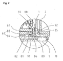
- the invention provides an axial displacement securing device 80 with a releasable clip connection between the coupling device, in particular the clutch hub 61 and rotary feedthrough 62, instead of a screw connection of the coupling device and rotary feedthrough 62 known from the prior art.
- This displacement securing device 80 is designed in the manner of a disk 92, which extends radially from the casing 83 of the rotary feedthrough 62 to over the inner diameter of the clutch hub 61.
- the disc 92 opens on the inner peripheral side into a tubular sleeve 91, which end carries a circumferential or more distributed over the circumference locking lugs 81.
- This locking lug 81 or these latching noses engages or engage in one or more corresponding groove or grooves 82, which is or are located on the inner circumference of the jacket 83 of the rotary feedthrough 62.
- the anti-displacement device 80 is axially non-displaceably connected to the rotary feedthrough 62.
- the disc 92 thus prevents axial displacement of the clutch hub 61 relative to the rotary feedthrough 62nd
- FIG. 2 shows a section of a further embodiment of a motor vehicle clutch according to the invention, in which again a double clutch and also a second embodiment variant of a Axialverschiebe Anlagens founded are provided. Shown in turn is a two-part rotary feedthrough 62 of the type described above in detail comprising a jacket 83 and a sleeve 84 and a clutch hub 61 embracing this.
- this Axialverschiebe Anlagens is formed in the manner of a disc 92 which extends radially from the shell 83 of the rotary feedthrough 62 to the outer periphery of the clutch hub 61.
- the disc 92 opens, as before, on the inner circumference side into a tubular sleeve 91, which carries at its end a circumferential or a plurality of circumferentially distributed substantially radially protruding latching noses 81.
- This locking lug 81 or these latching noses engages or engage in one or more corresponding groove or grooves 82, which is or are located on the inner circumference of the jacket 83 of the rotary feedthrough 62.
- the anti-displacement device is axially immovably connected to the rotary feedthrough 62.
- the disc 92 thus prevents axial displacement of the clutch hub 61 relative to the rotary feedthrough 62nd
- thrust bearings 87, 88 (plain bearings) are provided on both radial surfaces of the disc 92 in the region of the clutch hub 61, in which the clutch hub 61 or the outer disc carrier 2 of the second clutch 2 are guided in a sliding manner in the present exemplary embodiment.
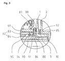
- FIG. 3 shows a section of a further embodiment of a motor vehicle clutch according to the invention, in which again a double clutch and further a further embodiment variant of a Axialverschiebeêt dress are provided. If one or more grooves or grooves 95 and 93 are introduced into the rotary feedthrough 62 and displacement securing device 80, then the axial securing can also be produced by a further component 94.
- FIG. 4 shows a section of one of a further embodiment of a motor vehicle clutch according to the invention, in which again a double clutch and also a further embodiment variant of a Axialverschiebeêt dress are provided.
- Their latching nose 81 or latching noses engages or engage in one or more corresponding groove or grooves 96, which is or are located on the outer circumference of the jacket 83 or the bushing 84 of the rotary feedthrough 62.
- the anti-displacement device 80 is axially non-displaceably connected to the rotary feedthrough 62.
- a plurality of locking lugs 85 are axially distributed from the rotary feedthrough 62 distributed over the circumference. These locking lugs 85 engage in corresponding radially extending grooves 86 in the shell 83 of the rotary feedthrough 62.
- This additional Verrast supplements prevents rotation of the anti-displacement device relative to the rotary feedthrough 62nd
Claims (7)
- Embrayage de véhicule automobile, présentant- un dispositif d'embrayage (K1, K2), notamment un dispositif d'embrayage double (K1, K2),- un joint rotatif (62), autour duquel le dispositif d'embrayage (K1, K2) est monté à rotation,- un dispositif (80) de fixation axiale du dispositif d'embrayage (K1, K2), avec un dispositif de crantage (81, 82),- le dispositif (80) pouvant être fixé axialement sur le joint rotatif (62) au moyen du dispositif de crantage (81, 82),caractérisé en ce que le dispositif de crantage (81, 82) présente un ergot de crantage (81) sur tout le pourtour, faisant saillie essentiellement radialement, ou plusieurs ergots de crantage (81) faisant saillie essentiellement radialement qui sont répartis sur le pourtour, ergot(s) qui est ou sont conçus pour pouvoir s'engager dans une rainure (82) ou plusieurs rainures (82) disposée(s) sur un pourtour intérieur ou sur un pourtour extérieur du joint rotatif (62).
- Embrayage de véhicule automobile selon la revendication 1, caractérisé en ce que le dispositif de crantage et/ou le joint rotatif présente une ou des géométries de rainures disposées sur un diamètre intérieur et/ou extérieur, dans lesquelles s'engage un autre élément (94).
- Embrayage de véhicule automobile selon la revendication 1 ou 2, caractérisé en ce qu'il est prévu un autre dispositif de crantage (81, 82 ; 85, 86) pour la fixation en solidarité de rotation du dispositif (80) sur le joint rotatif (62).
- Embrayage de véhicule automobile selon la revendication 3, caractérisé en ce que l'autre dispositif de crantage (81) présente plusieurs ergots de crantage (81) faisant saillie essentiellement radialement qui sont répartis sur le pourtour, ergots qui sont conçus pour pouvoir s'engager dans plusieurs rainures (82) disposées sur un pourtour intérieur ou sur un pourtour extérieur du joint rotatif (62).
- Embrayage de véhicule automobile selon la revendication 3 ou 4, caractérisé en ce que l'autre dispositif de crantage (85, 86) présente plusieurs ergots de crantage (85) faisant saillie essentiellement axialement qui sont répartis sur le pourtour, ergots qui sont conçus pour pouvoir s'engager dans des rainures correspondantes (82) disposées sur le joint rotatif (62).
- Embrayage de véhicule automobile selon l'une quelconque des revendications 3 à 5, caractérisé en ce que l'autre dispositif de crantage est constitué, en remplacement ou en complément, par des évidements (98) dans le dispositif de fixation axiale d'un dispositif d'embrayage, dans lesquels s'engagent des géométries (97) faisant axialement saillie sur le joint rotatif (62) et/ou sur d'autres éléments.
- Embrayage de véhicule automobile selon l'une quelconque des revendications précédentes, caractérisé en ce qu'il est prévu au moins un ensemble de palier lisse (87, 88) pour un élément limitrophe du dispositif (80).
Priority Applications (8)
| Application Number | Priority Date | Filing Date | Title |
|---|---|---|---|
| EP04013095A EP1515059B1 (fr) | 2003-09-09 | 2004-06-03 | Dispositif de fixation axiale d'un embrayage sur un joint rotatif |
| US11/628,391 US8056691B2 (en) | 2004-06-03 | 2005-06-01 | Device for axially positioning a clutch device |
| PCT/EP2005/005856 WO2005119080A1 (fr) | 2004-06-03 | 2005-06-01 | Dispositif de positionnement axial d'un systeme d'embrayage |
| EP05752882A EP1751444B1 (fr) | 2004-06-03 | 2005-06-01 | Systeme d' embrayage, en particulier systeme d'embrayage double, avec un dispositif de positionnement axial du systeme d'embrayage |
| JP2007513841A JP4959553B2 (ja) | 2004-06-03 | 2005-06-01 | クラッチ装置を軸方向に位置決めする装置 |
| DE502005005267T DE502005005267D1 (de) | 2004-06-03 | 2005-06-01 | Kupplungseinrichtung , insbesondere doppelkupplungseinrichtung, mit einer einrichtung zur axialen positionierung der kupplungseinrichtung |
| KR1020077000165A KR20070024704A (ko) | 2004-06-03 | 2005-06-01 | 클러치 장치를 축방향으로 지지하기 위한 장치 |
| CNB2005800181754A CN100538100C (zh) | 2004-06-03 | 2005-06-01 | 用于对离合器机构进行轴向定位的装置 |
Applications Claiming Priority (5)
| Application Number | Priority Date | Filing Date | Title |
|---|---|---|---|
| EP03020332A EP1496288B1 (fr) | 2003-07-07 | 2003-09-09 | Amortisseur de vibrations torsionelles |
| EP03020332 | 2003-09-09 | ||
| EP03023013 | 2003-10-11 | ||
| EP03023013A EP1522753B1 (fr) | 2003-10-11 | 2003-10-11 | Embrayage double hydraulique |
| EP04013095A EP1515059B1 (fr) | 2003-09-09 | 2004-06-03 | Dispositif de fixation axiale d'un embrayage sur un joint rotatif |
Publications (2)
| Publication Number | Publication Date |
|---|---|
| EP1515059A1 EP1515059A1 (fr) | 2005-03-16 |
| EP1515059B1 true EP1515059B1 (fr) | 2008-03-19 |
Family
ID=34970758
Family Applications (2)
| Application Number | Title | Priority Date | Filing Date |
|---|---|---|---|
| EP04013095A Expired - Fee Related EP1515059B1 (fr) | 2003-09-09 | 2004-06-03 | Dispositif de fixation axiale d'un embrayage sur un joint rotatif |
| EP05752882A Active EP1751444B1 (fr) | 2004-06-03 | 2005-06-01 | Systeme d' embrayage, en particulier systeme d'embrayage double, avec un dispositif de positionnement axial du systeme d'embrayage |
Family Applications After (1)
| Application Number | Title | Priority Date | Filing Date |
|---|---|---|---|
| EP05752882A Active EP1751444B1 (fr) | 2004-06-03 | 2005-06-01 | Systeme d' embrayage, en particulier systeme d'embrayage double, avec un dispositif de positionnement axial du systeme d'embrayage |
Country Status (7)
| Country | Link |
|---|---|
| US (1) | US8056691B2 (fr) |
| EP (2) | EP1515059B1 (fr) |
| JP (1) | JP4959553B2 (fr) |
| KR (1) | KR20070024704A (fr) |
| CN (1) | CN100538100C (fr) |
| DE (1) | DE502005005267D1 (fr) |
| WO (1) | WO2005119080A1 (fr) |
Cited By (1)
| Publication number | Priority date | Publication date | Assignee | Title |
|---|---|---|---|---|
| EP2732174B1 (fr) | 2011-07-15 | 2017-08-09 | Schaeffler Technologies AG & Co. KG | Double embrayage |
Families Citing this family (29)
| Publication number | Priority date | Publication date | Assignee | Title |
|---|---|---|---|---|
| JP2007170632A (ja) * | 2005-12-26 | 2007-07-05 | Hitachi Ltd | 回転軸の軸方向位置の変動に非干渉のクラッチ機構 |
| KR100820101B1 (ko) * | 2006-09-22 | 2008-04-07 | 현대자동차주식회사 | 축 밀림 방지 볼트 |
| JP4858093B2 (ja) * | 2006-11-07 | 2012-01-18 | マツダ株式会社 | 自動変速機 |
| DE502007000531D1 (de) * | 2007-01-26 | 2009-04-30 | Hoerbiger & Co | Verfahren zur Herstellung eines Kupplungskorbes einer Doppelkupplung |
| US8479905B2 (en) | 2007-03-30 | 2013-07-09 | Eaton Corporation | Dual clutch arrangement with two piece main rotating manifold |
| DE102007041575B4 (de) | 2007-09-01 | 2016-09-15 | Borgwarner Inc. | Verfahren zur Montageüberwachung von Mehrfachkupplungsmodulen in Getrieben |
| DE102007058852A1 (de) * | 2007-12-06 | 2009-06-25 | Schaeffler Kg | Mehrfachkupplungsvorrichtung |
| DE102008031865A1 (de) * | 2008-02-15 | 2009-08-20 | Borgwarner Inc., Auburn Hills | Kupplungseinrichtung mit einer Welle und einem Nabenteil |
| DE102008032273B4 (de) * | 2008-02-18 | 2021-12-23 | Borgwarner Inc. | Kupplungseinrichtung mit einer Flexplatte |
| EP2310707B1 (fr) * | 2008-07-14 | 2012-12-05 | Schaeffler Technologies AG & Co. KG | Embrayage double |
| DE102010024150B4 (de) * | 2009-07-09 | 2019-10-10 | Schaeffler Technologies AG & Co. KG | Druckverteilungskolben |
| DE102010010922B4 (de) * | 2009-08-14 | 2019-06-19 | Borgwarner Inc. | Parallele Doppelkupplungseinrichtung und Antriebsstrang mit einer solchen parallelen Doppelkupplungseinrichtung |
| DE102010021036A1 (de) * | 2010-05-19 | 2011-11-24 | Audi Ag | Doppelkupplung für ein Doppelkupplungs-Wechselgetriebe in Kraftfahrzeugen |
| DE102010034128A1 (de) | 2010-08-12 | 2012-02-16 | Borgwarner Inc. | Parallele Doppelkupplungseinrichtung |
| DE102010046633B4 (de) * | 2010-09-20 | 2012-10-18 | Gkn Stromag Ag | Doppelschaltkupplung |
| DE102011115286A1 (de) * | 2011-09-29 | 2013-04-04 | Borgwarner Inc. | Parallele Doppelkupplungseinrichtung |
| DE102012221958A1 (de) * | 2011-12-15 | 2013-06-20 | Schaeffler Technologies AG & Co. KG | Doppelkupplung |
| DE112012005428A5 (de) * | 2011-12-22 | 2014-09-25 | Schaeffler Technologies Gmbh & Co. Kg | Doppelkupplung |
| US8991583B2 (en) | 2012-04-19 | 2015-03-31 | Gm Global Technology Operations, Llc | Spring pack for a transmission |
| DE102012008779A1 (de) * | 2012-04-28 | 2013-10-31 | Volkswagen Aktiengesellschaft | Kupplung |
| DE102013221144A1 (de) * | 2012-11-12 | 2014-05-15 | Schaeffler Technologies Gmbh & Co. Kg | Deckelfester Ausrücker |
| US9180766B2 (en) * | 2013-12-16 | 2015-11-10 | Ford Global Technologies, Llc | Front module for a modular hybrid transmission and a method for connecting/disconnecting the front module from a torque converter |
| DE102014203400A1 (de) * | 2014-02-25 | 2015-08-27 | Volkswagen Aktiengesellschaft | Getriebeanordnung für ein Kraftfahrzeug |
| DE102016125264A1 (de) * | 2016-10-26 | 2018-04-26 | Schaeffler Technologies AG & Co. KG | Doppelkupplung mit radial befestigten Lamellenträgern und Bausatz aus Doppelkupplung und Schwungrad |
| FR3067077B1 (fr) * | 2017-05-31 | 2019-12-06 | Valeo Embrayages | Mecanisme d'embrayage comprenant deux ensembles relies par un dispositif d'assemblage |
| FR3084707B1 (fr) * | 2018-07-31 | 2021-11-26 | Valeo Embrayages | Mecanisme d'embrayage humide et module de transmission de couple comprenant ce mecanisme d'embrayage humide |
| FR3084708B1 (fr) * | 2018-07-31 | 2021-11-26 | Valeo Embrayages | Mecanisme d'embrayage humide et module de transmission de couple comprenant ce mecanisme d'embrayage humide |
| KR102618258B1 (ko) * | 2018-12-28 | 2023-12-27 | 주식회사 카펙발레오 | 차량용 듀얼 클러치 장치 |
| CN114810848A (zh) * | 2021-01-18 | 2022-07-29 | 杜泽儒 | 齿轮双向离合机构 |
Family Cites Families (17)
| Publication number | Priority date | Publication date | Assignee | Title |
|---|---|---|---|---|
| US1801590A (en) * | 1928-06-19 | 1931-04-21 | James T Dickson | Clutch and operating device |
| GB465612A (en) * | 1935-11-09 | 1937-05-10 | Bristol Aeroplane Co Ltd | Improvements in or relating to controlling gear for friction clutches |
| GB812784A (en) * | 1956-02-29 | 1959-04-29 | Snow Nabstedt Gear Corp | A reversing drive mechanism |
| US2863537A (en) * | 1957-03-04 | 1958-12-09 | Lipe Rollway Corp | Heavy duty friction clutch |
| US3077252A (en) * | 1959-10-22 | 1963-02-12 | Alexander C Smith | Clutch-brake unit |
| US3384214A (en) * | 1965-04-16 | 1968-05-21 | Int Harvester Co | Dual piston clutch |
| US3472350A (en) * | 1968-01-19 | 1969-10-14 | Twin Disc Inc | Hydraulically operated friction clutch of the dual actuating chamber type having a sequencing valve |
| FR2554057B1 (fr) * | 1983-10-28 | 1988-04-29 | Guitel Etienne Mobilor | Dispositif de blocage axial d'une roue en bout d'arbre |
| US5135088A (en) * | 1991-07-18 | 1992-08-04 | Power Transmission Technology, Inc. | Compact torque limiting clutch |
| US5676228A (en) * | 1996-02-16 | 1997-10-14 | Lin; Chun-Huo | Rear hub structure for bicycles |
| NL1003523C2 (nl) * | 1996-07-05 | 1998-01-07 | Crown Gear Holding B V | Keerkoppeling. |
| JP3625591B2 (ja) * | 1996-10-31 | 2005-03-02 | ジヤトコ株式会社 | 自動変速機の締結装置 |
| DE19647589C1 (de) * | 1996-11-18 | 1998-02-26 | Faure Bertrand Sitztech Gmbh | Ringförmiges Sicherungselement |
| DE19921687C5 (de) | 1999-05-12 | 2016-06-09 | Borgwarner Inc. | Mehrfach-Kupplungssystem für ein Getriebe |
| JP3402462B2 (ja) * | 2000-04-18 | 2003-05-06 | ダイハツ工業株式会社 | クラッチ構造 |
| DE50001452D1 (de) * | 2000-10-05 | 2003-04-17 | Ford Global Tech Inc | Doppelkupplung für ein Getriebe mit zwei Getriebeeingangswellen |
| DE20108155U1 (de) * | 2001-05-15 | 2001-10-11 | Kun Teng Industry Co | Radnabe für ein Fahrrad |
-
2004
- 2004-06-03 EP EP04013095A patent/EP1515059B1/fr not_active Expired - Fee Related
-
2005
- 2005-06-01 KR KR1020077000165A patent/KR20070024704A/ko not_active Application Discontinuation
- 2005-06-01 EP EP05752882A patent/EP1751444B1/fr active Active
- 2005-06-01 WO PCT/EP2005/005856 patent/WO2005119080A1/fr active IP Right Grant
- 2005-06-01 JP JP2007513841A patent/JP4959553B2/ja active Active
- 2005-06-01 DE DE502005005267T patent/DE502005005267D1/de active Active
- 2005-06-01 US US11/628,391 patent/US8056691B2/en active Active
- 2005-06-01 CN CNB2005800181754A patent/CN100538100C/zh active Active
Cited By (1)
| Publication number | Priority date | Publication date | Assignee | Title |
|---|---|---|---|---|
| EP2732174B1 (fr) | 2011-07-15 | 2017-08-09 | Schaeffler Technologies AG & Co. KG | Double embrayage |
Also Published As
| Publication number | Publication date |
|---|---|
| CN100538100C (zh) | 2009-09-09 |
| KR20070024704A (ko) | 2007-03-02 |
| JP4959553B2 (ja) | 2012-06-27 |
| US20080196994A1 (en) | 2008-08-21 |
| EP1751444A1 (fr) | 2007-02-14 |
| DE502005005267D1 (de) | 2008-10-16 |
| CN1989355A (zh) | 2007-06-27 |
| JP2008501895A (ja) | 2008-01-24 |
| EP1751444B1 (fr) | 2008-09-03 |
| EP1515059A1 (fr) | 2005-03-16 |
| WO2005119080A1 (fr) | 2005-12-15 |
| US8056691B2 (en) | 2011-11-15 |
Similar Documents
| Publication | Publication Date | Title |
|---|---|---|
| EP1515059B1 (fr) | Dispositif de fixation axiale d'un embrayage sur un joint rotatif | |
| EP1522753B1 (fr) | Embrayage double hydraulique | |
| EP1941171B1 (fr) | Dispositif d'accouplement servant a transmettre un couple de rotation | |
| EP2109722B1 (fr) | Dispositif de transmission de couple | |
| EP2310704B1 (fr) | Embrayage double | |
| EP1427948B1 (fr) | Combination d'un systeme d'embrayage multiple et d'une machine electrique | |
| EP1568906B1 (fr) | Embrayage double | |
| DE10223780C1 (de) | Gangschaltgetriebe für ein Kraftfahrzeug mit hydraulisch betätigbarer Mehrfachkupplung | |
| DE112011103372B4 (de) | Doppelkupplung | |
| EP3139053B1 (fr) | Double embrayage dote d'un piston vertical et de butees d'embrayage ameliorees | |
| EP1726842B1 (fr) | Ensemble embrayage avec embrayages voisins dans le sens radial. | |
| DE102006048653A1 (de) | Kopplungseinrichtung zur Übertragung eines Drehmoments | |
| WO2010081451A1 (fr) | Ensemble embrayage | |
| EP1882865B1 (fr) | DIspositif d'embrayage pour la boîte de vitesses d'un véhicule | |
| EP1522752A1 (fr) | Dispositif d'entrainement | |
| EP1729025B1 (fr) | Dispositif d'embrayage multiple | |
| DE102006042057A1 (de) | Kupplungsanordnung | |
| EP1726847B1 (fr) | Combinaison d'un ammortisseur de torsion avec un embrayage | |
| EP1614919B1 (fr) | Ensemble d'embrayage | |
| WO2019166048A1 (fr) | Système d'embrayage et unité d'entraînement présentant ce système d'embrayage | |
| DE102007057432B4 (de) | Hydrodynamische Kopplungseinrichtung | |
| EP1916146A2 (fr) | Système d'entraînement hybride pour un véhicule | |
| WO2010105958A1 (fr) | Système de transfert de couple pour la chaîne cinématique d'un véhicule | |
| DE102011017652A1 (de) | Hydrodynamische Kopplungsanordnung, insbesondere hydrodynamischer Drehmomentwandler | |
| DE102004036519A1 (de) | Kupplungsanordnung |
Legal Events
| Date | Code | Title | Description |
|---|---|---|---|
| PUAI | Public reference made under article 153(3) epc to a published international application that has entered the european phase |
Free format text: ORIGINAL CODE: 0009012 |
|
| AK | Designated contracting states |
Kind code of ref document: A1 Designated state(s): AT BE BG CH CY CZ DE DK EE ES FI FR GB GR HU IE IT LI LU MC NL PL PT RO SE SI SK TR |
|
| AX | Request for extension of the european patent |
Extension state: AL HR LT LV MK |
|
| 17P | Request for examination filed |
Effective date: 20050525 |
|
| RAP1 | Party data changed (applicant data changed or rights of an application transferred) |
Owner name: BORGWARNER INC. |
|
| RAP1 | Party data changed (applicant data changed or rights of an application transferred) |
Owner name: BORGWARNER INC. |
|
| AKX | Designation fees paid |
Designated state(s): DE FR GB IT |
|
| 17Q | First examination report despatched |
Effective date: 20050715 |
|
| GRAP | Despatch of communication of intention to grant a patent |
Free format text: ORIGINAL CODE: EPIDOSNIGR1 |
|
| GRAS | Grant fee paid |
Free format text: ORIGINAL CODE: EPIDOSNIGR3 |
|
| GRAA | (expected) grant |
Free format text: ORIGINAL CODE: 0009210 |
|
| AK | Designated contracting states |
Kind code of ref document: B1 Designated state(s): DE FR GB IT |
|
| REG | Reference to a national code |
Ref country code: GB Ref legal event code: FG4D Free format text: NOT ENGLISH |
|
| REF | Corresponds to: |
Ref document number: 502004006555 Country of ref document: DE Date of ref document: 20080430 Kind code of ref document: P |
|
| ET | Fr: translation filed | ||
| PLBE | No opposition filed within time limit |
Free format text: ORIGINAL CODE: 0009261 |
|
| STAA | Information on the status of an ep patent application or granted ep patent |
Free format text: STATUS: NO OPPOSITION FILED WITHIN TIME LIMIT |
|
| 26N | No opposition filed |
Effective date: 20081222 |
|
| PGFP | Annual fee paid to national office [announced via postgrant information from national office to epo] |
Ref country code: IT Payment date: 20090622 Year of fee payment: 6 |
|
| PGFP | Annual fee paid to national office [announced via postgrant information from national office to epo] |
Ref country code: GB Payment date: 20090507 Year of fee payment: 6 |
|
| GBPC | Gb: european patent ceased through non-payment of renewal fee |
Effective date: 20100603 |
|
| PG25 | Lapsed in a contracting state [announced via postgrant information from national office to epo] |
Ref country code: IT Free format text: LAPSE BECAUSE OF NON-PAYMENT OF DUE FEES Effective date: 20100603 |
|
| PG25 | Lapsed in a contracting state [announced via postgrant information from national office to epo] |
Ref country code: GB Free format text: LAPSE BECAUSE OF NON-PAYMENT OF DUE FEES Effective date: 20100603 |
|
| REG | Reference to a national code |
Ref country code: FR Ref legal event code: PLFP Year of fee payment: 13 |
|
| REG | Reference to a national code |
Ref country code: FR Ref legal event code: PLFP Year of fee payment: 14 |
|
| REG | Reference to a national code |
Ref country code: FR Ref legal event code: PLFP Year of fee payment: 15 |
|
| PGFP | Annual fee paid to national office [announced via postgrant information from national office to epo] |
Ref country code: DE Payment date: 20190515 Year of fee payment: 16 |
|
| PGFP | Annual fee paid to national office [announced via postgrant information from national office to epo] |
Ref country code: FR Payment date: 20190522 Year of fee payment: 16 |
|
| REG | Reference to a national code |
Ref country code: DE Ref legal event code: R119 Ref document number: 502004006555 Country of ref document: DE |
|
| PG25 | Lapsed in a contracting state [announced via postgrant information from national office to epo] |
Ref country code: FR Free format text: LAPSE BECAUSE OF NON-PAYMENT OF DUE FEES Effective date: 20200630 |
|
| PG25 | Lapsed in a contracting state [announced via postgrant information from national office to epo] |
Ref country code: DE Free format text: LAPSE BECAUSE OF NON-PAYMENT OF DUE FEES Effective date: 20210101 |