EP1515059B1 - Device for axially securing a clutch device on a rotary joint - Google Patents
Device for axially securing a clutch device on a rotary joint Download PDFInfo
- Publication number
- EP1515059B1 EP1515059B1 EP04013095A EP04013095A EP1515059B1 EP 1515059 B1 EP1515059 B1 EP 1515059B1 EP 04013095 A EP04013095 A EP 04013095A EP 04013095 A EP04013095 A EP 04013095A EP 1515059 B1 EP1515059 B1 EP 1515059B1
- Authority
- EP
- European Patent Office
- Prior art keywords
- clutch
- latching
- rotary joint
- motor vehicle
- circumference
- Prior art date
- Legal status (The legal status is an assumption and is not a legal conclusion. Google has not performed a legal analysis and makes no representation as to the accuracy of the status listed.)
- Expired - Lifetime
Links
Images

Classifications
-
- F—MECHANICAL ENGINEERING; LIGHTING; HEATING; WEAPONS; BLASTING
- F16—ENGINEERING ELEMENTS AND UNITS; GENERAL MEASURES FOR PRODUCING AND MAINTAINING EFFECTIVE FUNCTIONING OF MACHINES OR INSTALLATIONS; THERMAL INSULATION IN GENERAL
- F16D—COUPLINGS FOR TRANSMITTING ROTATION; CLUTCHES; BRAKES
- F16D25/00—Fluid-actuated clutches
- F16D25/06—Fluid-actuated clutches in which the fluid actuates a piston incorporated in, i.e. rotating with the clutch
- F16D25/062—Fluid-actuated clutches in which the fluid actuates a piston incorporated in, i.e. rotating with the clutch the clutch having friction surfaces
- F16D25/063—Fluid-actuated clutches in which the fluid actuates a piston incorporated in, i.e. rotating with the clutch the clutch having friction surfaces with clutch members exclusively moving axially
- F16D25/0635—Fluid-actuated clutches in which the fluid actuates a piston incorporated in, i.e. rotating with the clutch the clutch having friction surfaces with clutch members exclusively moving axially with flat friction surfaces, e.g. discs
- F16D25/0638—Fluid-actuated clutches in which the fluid actuates a piston incorporated in, i.e. rotating with the clutch the clutch having friction surfaces with clutch members exclusively moving axially with flat friction surfaces, e.g. discs with more than two discs, e.g. multiple lamellae
-
- F—MECHANICAL ENGINEERING; LIGHTING; HEATING; WEAPONS; BLASTING
- F16—ENGINEERING ELEMENTS AND UNITS; GENERAL MEASURES FOR PRODUCING AND MAINTAINING EFFECTIVE FUNCTIONING OF MACHINES OR INSTALLATIONS; THERMAL INSULATION IN GENERAL
- F16D—COUPLINGS FOR TRANSMITTING ROTATION; CLUTCHES; BRAKES
- F16D21/00—Systems comprising a plurality of actuated clutches
- F16D21/02—Systems comprising a plurality of actuated clutches for interconnecting three or more shafts or other transmission members in different ways
- F16D21/06—Systems comprising a plurality of actuated clutches for interconnecting three or more shafts or other transmission members in different ways at least two driving shafts or two driven shafts being concentric
-
- F—MECHANICAL ENGINEERING; LIGHTING; HEATING; WEAPONS; BLASTING
- F16—ENGINEERING ELEMENTS AND UNITS; GENERAL MEASURES FOR PRODUCING AND MAINTAINING EFFECTIVE FUNCTIONING OF MACHINES OR INSTALLATIONS; THERMAL INSULATION IN GENERAL
- F16D—COUPLINGS FOR TRANSMITTING ROTATION; CLUTCHES; BRAKES
- F16D25/00—Fluid-actuated clutches
- F16D25/10—Clutch systems with a plurality of fluid-actuated clutches
-
- F—MECHANICAL ENGINEERING; LIGHTING; HEATING; WEAPONS; BLASTING
- F16—ENGINEERING ELEMENTS AND UNITS; GENERAL MEASURES FOR PRODUCING AND MAINTAINING EFFECTIVE FUNCTIONING OF MACHINES OR INSTALLATIONS; THERMAL INSULATION IN GENERAL
- F16D—COUPLINGS FOR TRANSMITTING ROTATION; CLUTCHES; BRAKES
- F16D25/00—Fluid-actuated clutches
- F16D25/12—Details not specific to one of the before-mentioned types
-
- F—MECHANICAL ENGINEERING; LIGHTING; HEATING; WEAPONS; BLASTING
- F16—ENGINEERING ELEMENTS AND UNITS; GENERAL MEASURES FOR PRODUCING AND MAINTAINING EFFECTIVE FUNCTIONING OF MACHINES OR INSTALLATIONS; THERMAL INSULATION IN GENERAL
- F16D—COUPLINGS FOR TRANSMITTING ROTATION; CLUTCHES; BRAKES
- F16D21/00—Systems comprising a plurality of actuated clutches
- F16D21/02—Systems comprising a plurality of actuated clutches for interconnecting three or more shafts or other transmission members in different ways
- F16D21/06—Systems comprising a plurality of actuated clutches for interconnecting three or more shafts or other transmission members in different ways at least two driving shafts or two driven shafts being concentric
- F16D2021/0607—Double clutch with torque input plate in-between the two clutches, i.e. having a central input plate
-
- F—MECHANICAL ENGINEERING; LIGHTING; HEATING; WEAPONS; BLASTING
- F16—ENGINEERING ELEMENTS AND UNITS; GENERAL MEASURES FOR PRODUCING AND MAINTAINING EFFECTIVE FUNCTIONING OF MACHINES OR INSTALLATIONS; THERMAL INSULATION IN GENERAL
- F16D—COUPLINGS FOR TRANSMITTING ROTATION; CLUTCHES; BRAKES
- F16D21/00—Systems comprising a plurality of actuated clutches
- F16D21/02—Systems comprising a plurality of actuated clutches for interconnecting three or more shafts or other transmission members in different ways
- F16D21/06—Systems comprising a plurality of actuated clutches for interconnecting three or more shafts or other transmission members in different ways at least two driving shafts or two driven shafts being concentric
- F16D2021/0661—Hydraulically actuated multiple lamellae clutches
-
- F—MECHANICAL ENGINEERING; LIGHTING; HEATING; WEAPONS; BLASTING
- F16—ENGINEERING ELEMENTS AND UNITS; GENERAL MEASURES FOR PRODUCING AND MAINTAINING EFFECTIVE FUNCTIONING OF MACHINES OR INSTALLATIONS; THERMAL INSULATION IN GENERAL
- F16D—COUPLINGS FOR TRANSMITTING ROTATION; CLUTCHES; BRAKES
- F16D21/00—Systems comprising a plurality of actuated clutches
- F16D21/02—Systems comprising a plurality of actuated clutches for interconnecting three or more shafts or other transmission members in different ways
- F16D21/06—Systems comprising a plurality of actuated clutches for interconnecting three or more shafts or other transmission members in different ways at least two driving shafts or two driven shafts being concentric
- F16D2021/0692—Systems comprising a plurality of actuated clutches for interconnecting three or more shafts or other transmission members in different ways at least two driving shafts or two driven shafts being concentric with two clutches arranged axially without radial overlap
Definitions
- This further latching device may, for example, have a plurality of circumferentially distributed substantially radially projecting locking lugs, which are formed in a plurality of arranged on an inner circumference or on an outer circumference of the rotary feedthrough grooves, recesses or the like engageable.
- At least one slide bearing device can be provided for an adjacent component of the device. Separate insertion of plain bearings, bearings and / or contact surfaces is no longer required, which also offers advantages in terms of assembly.
- the first transmission input shaft (central or solid shaft 10) can be used for the operation of all odd gears (eg 1, 3, 5 %) and the second transmission input shaft (hollow shaft 9) for the operation of all even gears (eg. 2, 4, 6 ...) of the motor vehicle.
- the reverse gear could be assigned to both the first transmission input shaft (central or solid shaft 10), and the second transmission input shaft (solid shaft 9) of the transmission G.
- the torsion or vibration damper 12 is formed in a manner known per se. On the input side, it has a primary element 14 in the form of a half-shell. On the output side, a secondary element consisting of a first half-shell 13 and a second half-shell 11, which also forms the coupling housing, is provided. Primary element 14 and Secondary element 13, 11 are coupled via a plurality of arranged on the outer circumference of the torsional vibration damper spring assemblies 12 in the rotational direction a torque transferable. As an example, a spring package is shown in the drawing.
- Each clutch K1, K2 comprises in each case an outer disk carrier 1, 2 and a common inner disk carrier 40.
- the outer disk carrier of the first clutch K1 is referred to below as the first outer disk carrier 1
- the outer disk carrier of the second clutch K2 is referred to below as the second outer disk carrier 2.
- the two outer disk carrier 1, 2 are formed in a half-shell-shaped, wherein the first outer disk carrier 1 surrounds the second outer disk carrier 2 in the axial direction outstanding.
- the inner disk carrier 40 has a substantially cylindrical shape and extends over the axially extending regions of the half-shell-shaped outer disk carrier 1, 2.
- the two outer disk carriers 1, 2 have internal toothings 5, 6, which serve for the axially displaceable but essentially non-rotatable guidance of friction disks 29, 30 having four respective external toothings 31, 32 in the present case.
- the latter are usually also referred to as outer plates 29, 30.
- the common inner disk carrier 40 outer teeth 41, 42 are arranged in which internal teeth having friction plates, the so-called inner plates 36, axially displaceable but rotatably guided.
- the two inner disk carrier sections are separated from each other by a common end plate 35.
- the outer friction disks / outer disks 29, 30, the inner friction disks / inner disks 33, 36 and the two pressure plates 34, 37 and the common end plate 35 engage each other in a manner known per se in a manner known per se to form a disk set 27, 28 associated with a clutch K1, K2 each other.
- the two disk sets 27, 28 with the corresponding friction plates 29, 30, 33, 34, 35, 36, 37 are thus arranged one behind the other on the common inner disk carrier 40 in the axial direction.
- the friction surfaces of all friction plates 29, 30, 33, 34, 35, 36, 37 are substantially the same size, so that the individual clutches K1, K2 have equivalent performance.
- the friction surfaces of the friction plates 29, 30, 33, 34, 35, 36, 37 have different sized outer and / or inner diameter.
- piston / cylinder units which serve to actuate the clutches K1, K2.
- everyone is Coupling K1, K2 associated with a hydraulically actuated actuating piston 43, 44.
- Each of these actuating piston 43, 44 can against one of the pressure plates 34, 37 force-transmitting and frictional engagement between the individual friction plates 29, 30, 33, 34, 35, 36, 37 generating and thus the respective clutch K1, K2 pressed pressed.
- Part of the clutch housing 11 is a cylinder 79 in to the cylinder 77 corresponding type. At the two cylinders 77, 79, the respective actuating piston 43, 44 are guided axially displaceable. Cylinder 77 and actuating piston 44 serve as a support and centering for the inner disk carrier 40th
- the actuators for the two clutches K1, K2 include, in addition to the aforementioned actuating piston 43, 44, by means of which the respective pressure plates 34, 37 of the disk packs 27, 28 can be moved in the direction of the common end plates 35, each a pressure piston 49, 50, a piston 51, 52, a compensating piston 55, 56 and a plurality of circumferentially arranged coil springs 53, 54.
- the respective actuating piston 43, 44 are supported against the respective pressure piston 49, 50 from which axially displaceably on the cylinders 79, 77 and Outer circumference of the clutch hub 61 are guided. Inwardly directed, the actuating pistons 43, 44 are supported against the pistons 51, 52.
- a separate rotary feedthrough 62 is provided, which surrounds the two transmission input shafts, the hollow shaft 9 and the solid shaft 10 coaxially and on which the clutch hub 61st is rotatably supported by means of a radial roller bearing 89 and a radial ball bearing 90.
- the rotary feedthrough 62 can be made in one piece or both axially and radially in several parts.
- the rotary feedthrough 62 is made in two parts. It consists of a jacket 83 and a bushing 84 enclosed by the latter.
- the cylinder jacket-shaped bushing 84 has, in its outer circumference, longitudinal grooves extending in the axial and / or radial direction of different lengths.
- the jacket 83 has corresponding to the arrangement of the aforementioned longitudinal grooves on four circumferentially extending grooves. These circumferential grooves are connected via radially extending openings, not shown here, with the corresponding longitudinal grooves.
- the coupling hub 61 has four substantially radially and partially axially inclined openings, which are hereinafter referred to as hydraulic fluid channels 63, 64, 65 and 66.
- hydraulic fluid channels 63, 64, 65 and 66 Via the grooves in the bushing 84, the openings and grooves in the shell 83 and the hydraulic fluid channels 63, 64, 65, 66 in the clutch hub 61, a supply of the volume formed by the pistons 43, 44, 49, 50, 55, 56 first hydraulic fluid actuating chamber 71, second hydraulic fluid actuating chamber 72, first hydraulic fluid compensation chamber 69, second hydraulic fluid compensation chamber 70, cooling fluid chamber 73) with hydraulic fluid.
- the hydraulic fluid compensation chambers 69, 70 and the cooling fluid chamber 73 are filled with hydraulic fluid via the two hydraulic fluid channels 64 and 65.
- the hydraulic fluid in the hydraulic fluid compensation chambers 69, 70 serves to generate a centrifugally induced hydraulic fluid back pressure, which counteracts the centrifugal pressure increase in the respective hydraulic fluid actuating chamber 71, 72.
- the hydraulic fluid in the cooling liquid space 73 is for cooling the friction plates 29 30 33, 34, 35, 36, 37 by radially extending (not shown here) openings in the inner disk carrier 40 to the friction plates 29, 30, 33, 34, 35, 36, 37 out ,
- the drive train components described in detail above are connected together as follows.
- the crankshaft 24 is bolted to the inner periphery of the flywheel 21 (screw 26, bore 23).
- the outer circumference of the flywheel 21 is riveted to the outer periphery of the bending / tumble disc 18 (outer edge bore 19, rivets 20, bore 22).
- the inner circumference of the bending / tumbling disc 18 carries an inner flange 17 with external teeth. This external toothing engages in the manner of a spline 16 in an internal toothing of the primary element 14 of the torsional vibration damper 12 producing a rotationally fixed connection.
- the secondary element 13 of the torsional vibration damper 12, which also forms the clutch housing, is rotatably connected in the manner described above with the inner disk carrier 40 of the double clutch.
- the two clutches (disk packs 27, 28, actuating pistons 44, 45) connect the inner disk carrier 40 to the outer disk carriers 1, 2, which in turn are non-rotatably connected to the two transmission input shafts 9, 10 via their flanges 3, 4 by means of splines 7, 8.
- a torque introduced via the crankshaft 24 can thus be transmitted to one of the two transmission input shafts 9, 10 by means of the double clutch.
- a rotational movement introduced via the crankshaft 24 via a pump drive gear 68 arranged on the clutch hub 61 also drives a hydraulic pump, not shown here, for providing the above-mentioned hydraulic fluid pressure.
- the invention provides an axial displacement securing device 80 with a releasable clip connection between the coupling device, in particular the clutch hub 61 and rotary feedthrough 62, instead of a screw connection of the coupling device and rotary feedthrough 62 known from the prior art.
- This displacement securing device 80 is designed in the manner of a disk 92, which extends radially from the casing 83 of the rotary feedthrough 62 to over the inner diameter of the clutch hub 61.
- the disc 92 opens on the inner peripheral side into a tubular sleeve 91, which end carries a circumferential or more distributed over the circumference locking lugs 81.
- This locking lug 81 or these latching noses engages or engage in one or more corresponding groove or grooves 82, which is or are located on the inner circumference of the jacket 83 of the rotary feedthrough 62.
- the anti-displacement device 80 is axially non-displaceably connected to the rotary feedthrough 62.
- the disc 92 thus prevents axial displacement of the clutch hub 61 relative to the rotary feedthrough 62nd
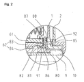
- FIG. 2 shows a section of a further embodiment of a motor vehicle clutch according to the invention, in which again a double clutch and also a second embodiment variant of a Axialverschiebe Anlagens founded are provided. Shown in turn is a two-part rotary feedthrough 62 of the type described above in detail comprising a jacket 83 and a sleeve 84 and a clutch hub 61 embracing this.
- this Axialverschiebe Anlagens is formed in the manner of a disc 92 which extends radially from the shell 83 of the rotary feedthrough 62 to the outer periphery of the clutch hub 61.
- the disc 92 opens, as before, on the inner circumference side into a tubular sleeve 91, which carries at its end a circumferential or a plurality of circumferentially distributed substantially radially protruding latching noses 81.
- This locking lug 81 or these latching noses engages or engage in one or more corresponding groove or grooves 82, which is or are located on the inner circumference of the jacket 83 of the rotary feedthrough 62.
- the anti-displacement device is axially immovably connected to the rotary feedthrough 62.
- the disc 92 thus prevents axial displacement of the clutch hub 61 relative to the rotary feedthrough 62nd
- thrust bearings 87, 88 (plain bearings) are provided on both radial surfaces of the disc 92 in the region of the clutch hub 61, in which the clutch hub 61 or the outer disc carrier 2 of the second clutch 2 are guided in a sliding manner in the present exemplary embodiment.
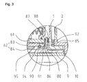
- FIG. 3 shows a section of a further embodiment of a motor vehicle clutch according to the invention, in which again a double clutch and further a further embodiment variant of a Axialverschiebeêt dress are provided. If one or more grooves or grooves 95 and 93 are introduced into the rotary feedthrough 62 and displacement securing device 80, then the axial securing can also be produced by a further component 94.
- FIG. 4 shows a section of one of a further embodiment of a motor vehicle clutch according to the invention, in which again a double clutch and also a further embodiment variant of a Axialverschiebeêt dress are provided.
- Their latching nose 81 or latching noses engages or engage in one or more corresponding groove or grooves 96, which is or are located on the outer circumference of the jacket 83 or the bushing 84 of the rotary feedthrough 62.
- the anti-displacement device 80 is axially non-displaceably connected to the rotary feedthrough 62.
- a plurality of locking lugs 85 are axially distributed from the rotary feedthrough 62 distributed over the circumference. These locking lugs 85 engage in corresponding radially extending grooves 86 in the shell 83 of the rotary feedthrough 62.
- This additional Verrast supplements prevents rotation of the anti-displacement device relative to the rotary feedthrough 62nd
Landscapes
- Engineering & Computer Science (AREA)
- General Engineering & Computer Science (AREA)
- Mechanical Engineering (AREA)
- Hydraulic Clutches, Magnetic Clutches, Fluid Clutches, And Fluid Joints (AREA)
- Mechanical Operated Clutches (AREA)
Description
Die Erfindung betrifft eine Kraftfahrzeugkupplung gemäß dem Oberbegriff des Patentanspruchs 1.The invention relates to a motor vehicle clutch according to the preamble of
Eine Doppelkupplung gemäß dem Stand der Technik, von der die Erfindung ausgeht, ist beispielsweise in der
Obwohl sich dieses Verfahren dem Grunde nach bewährt hat, ist es erforderlich, diese Verschraubung beim Montieren der Doppelkupplung an das Getriebe wieder zu lösen, was vergleichsweise umständlich ist. Danach muss die Kupplungseinrichtung an dem Getriebe axial fixiert werden.Although this method has been proven in principle, it is necessary to solve this screw when mounting the dual clutch to the transmission again, which is relatively cumbersome. Thereafter, the coupling device must be axially fixed to the transmission.
Die Aufgabe der Erfindung besteht daher darin, eine Kraftfahrzeugkupplung vorzustellen, welche komplett vormontiert wesentlich einfacher in einem (Fahrzeug) Getriebe montierbar und demontierbar ist.The object of the invention is to present a motor vehicle clutch which is completely pre-assembled much easier in a (vehicle) gear mountable and disassembled.
Diese Aufgabe wird durch eine Kraftfahrzeugkupplung mit den Merkmalen des Patentanspruchs 1 gelöst.This object is achieved by a motor vehicle coupling having the features of
Vorteilhafte Ausführungen und Weiterbildungen der Erfindung sind in den Unteransprüchen angegeben.Advantageous embodiments and further developments of the invention are specified in the subclaims.
Erfindungsgemäß ist demnach eine Verrasteinrichtung zur axialen Fixierung der Einrichtung an der Drehdurchführung vorgesehen, die eine umlaufende im wesentlichen radial abstehende Rastnase oder mehrere über den Umfang verteilte im wesentlichen radial abstehende Rastnasen aufweist, welche in eine oder mehrere an einem Innenumfang oder an einem Außenumfang der Drehdurchführung angeordnete Nut bzw. Nuten, Ausnehmung bzw. Ausnehmungen oder dergleichen eingreifbar ausgebildet ist bzw. sind.According to the invention a Verrasteinrichtung is provided for axially fixing the device to the rotary feedthrough having a circumferential substantially radially projecting locking lug or a plurality of circumferentially distributed substantially radially projecting locking lugs, which in one or more on an inner circumference or on an outer circumference of the rotary feedthrough arranged groove or grooves, recess or recesses or the like is formed engageable or are.
In besonders vorteilhafter Ausgestaltung der Erfindung ist eine weitere Verrasteinrichtung zur drehfesten Fixierung der Einrichtung an der Drehdurchführung und/ oder eindeutigen Festlegung einer Einbaulage um die Drehachse vorgesehen. Damit wird erreicht, dass das Bauteil nicht rotationssymmetrisch ausgeführt wird und dadurch weitere Funktionen realisiert werden können (Durchstellungen, Umlenkkanten für Ölführung). Des Weiteren setzt die Abstützung von Lagerkräften eine drehfeste Fixierung voraus.In a particularly advantageous embodiment of the invention, a further Verrasteinrichtung is provided for rotationally fixed fixing of the device to the rotary feedthrough and / or clear fixing an installation position about the axis of rotation. This ensures that the component is not rotationally symmetrical and thus other functions can be realized (Durchstellungen, deflection edges for oil supply). Furthermore, the support of bearing forces requires a rotationally fixed fixation.
Diese weitere Verrasteinrichtung kann beispielsweise mehrere über den Umfang verteilte im wesentlichen radial abstehende Rastnasen aufweisen, welche in mehrere an einem Innenumfang oder an einem Außenumfang der Drehdurchführung angeordnete Nuten, Ausnehmungen oder dergleichen eingreifbar ausgebildet sind.This further latching device may, for example, have a plurality of circumferentially distributed substantially radially projecting locking lugs, which are formed in a plurality of arranged on an inner circumference or on an outer circumference of the rotary feedthrough grooves, recesses or the like engageable.
Die weitere Verrasteinrichtung kann alternativ oder zusätzlich mehrere über den Umfang verteilte im wesentlichen axial abstehende Rastnasen aufweisen, welche in korrespondierende an der Drehdurchführung angeordnete Nuten, Ausnehmungen oder dergleichen eingreifbar ausgebildet sind.The further latching device may alternatively or additionally comprise a plurality of circumferentially distributed substantially axially projecting locking lugs, which are formed in corresponding arranged on the rotary feedthrough grooves, recesses or the like engageable.
Die weitere Verrasteinrichtung kann alternativ oder zusätzlich durch Ausnehmungen (Löcher, Rippen, Durchstellungen) in der Einrichtung zur axialen Sicherung einer Kupplungseinrichtung dargestellt werden, in die axial abstehende korrespondierende Geometrien (Nasen) an der Drehdurchführung und/ oder weiterer Bauteile eingreifen.The further latching device can alternatively or additionally be represented by recesses (holes, ribs, points) in the device for the axial securing of a coupling device in which axially projecting corresponding geometries (lugs) engage the rotary leadthrough and / or further components.
Schließlich kann wenigstens eine Gleitlagereinrichtung für ein angrenzendes Bauteil der Einrichtung vorgesehen sein. Ein separates Einsetzen von Gleitlagern, Wälzlagern und/ oder Anlaufflächen ist nicht mehr erforderlich, was ebenso Vorteile hinsichtlich der Montage bietet.Finally, at least one slide bearing device can be provided for an adjacent component of the device. Separate insertion of plain bearings, bearings and / or contact surfaces is no longer required, which also offers advantages in terms of assembly.
Zwei Ausführungsbeispiele der Erfindung sind in der Zeichnung dargestellt. Es zeigen:
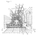
Figur 1- einen Antriebsstrang mit einem ersten Ausführungsbeispiel einer erfindungsgemäßen Kraftfahrzeugkupplung im Axialhalbschnitt
Figur 2- eine Detaildarstellung eines zweiten Ausführungsbeispiels einer erfindugsgemäßen Kraftfahrzeugkupplung im Axialhalbschnitt
Figur 3- eine Detaildarstellung eines dritten Ausführungsbeispiels einer erfindungsgemäßen Kraftfahrzeugkupplung im Axialhalbschnitt
Figur 4- eine Detaildarstellung eines vierten Ausführungsbeispiels einer erfindungsgemäßen Kraftfahrzeugkupplung im Axialhalbschnitt.
- FIG. 1
- a drive train with a first embodiment of a motor vehicle clutch according to the invention in Axialhalbschnitt
- FIG. 2
- a detailed view of a second embodiment of a erfindugsgemäßen motor vehicle clutch in Axialhalbschnitt
- FIG. 3
- a detailed representation of a third embodiment of a motor vehicle coupling according to the invention in the axial half section
- FIG. 4
- a detailed view of a fourth embodiment of a motor vehicle coupling according to the invention in Axialhalbschnitt.
Die
Auf der rechten Seite der Zeichnungsfigur ist eine als Antriebswelle dienende Kurbelwelle 24 angedeutet, welche beispielsweise mit einer Verbrennungskraftmaschine, einem Motor M oder dergleichen gekoppelt ist. Diese Seite stellt die Antriebsseite des Antriebsstrangs dar.On the right side of the drawing figure serving as a
Auf der linken Seite des Zeichnungsblattes sind zwei Getriebeeingangswellen, nämlich eine Zentral- oder Vollwelle 10 und eine Hohlwelle 9 zu sehen, welche aus der Kupplungsglocke 74 der Doppelkupplung herausgeführt sind und beispielsweise mit einem hier nicht dargestellten Getriebe G oder dergleichen gekoppelt sind. Diese Seite stellt die Abtriebsseite des Antriebsstrangs dar.On the left side of the drawing sheet two transmission input shafts, namely a central or
So kann beispielsweise die erste Getriebeeingangswelle (Zentral- oder Vollwelle 10) zum Betrieb aller ungeraden Gänge (z. B. 1, 3, 5 ...) und die zweite Getriebeeingangswelle (Hohlwelle 9) zum Betrieb aller geraden Gänge (z. B. 2, 4, 6 ...) des Kraftfahrzeugs vorgesehen sein. Der Rückwärtsgang könnte sowohl der ersten Getriebeeingangswelle (Zentral- oder Vollwelle 10), als auch der zweiten Getriebeeingangswelle (Vollwelle 9) des Getriebes G zugeordnet sein.For example, the first transmission input shaft (central or solid shaft 10) can be used for the operation of all odd gears (
Der Antriebsstrang umfasst ferner eine Schwungmasse 21, eine biege-/taumelweiche Scheibe 18, einen Torsionsschwingungsdämpfer 12 sowie die vorstehend genannte Doppelkupplung, mittels der die Abtriebswellen 9, 10 schaltbar mit der Antriebswelle 24 verbindbar sind.The drive train further includes a
Dieser Antriebsstrang wird von einem äußeren Gehäuse umschlossen. Dieses äußere Gehäuse wird durch eine Kupplungsglocke 74 gebildet. Diese Kupplungsglocke 74 umschließt die beiden als nasslaufende Lamellenkupplungen ausgeführten Kupplungen K1, K2, den Drehschwingungsdämpfer 12, die biege- und/oder taumelweiche Scheibe 18 sowie die Schwungmasse 21.This drive train is enclosed by an outer housing. This outer housing is formed by a
Es sei noch einmal explizit darauf hingewiesen, dass die Einheit aus Kupplung K1 und Kupplung K2 eine Kupplungseinrichtung im Sinne des Patentanspruchs 1 definiert.It should again be explicitly pointed out that the unit of clutch K1 and clutch K2 defines a clutch device in the sense of
Der Dreh- oder Torsionsschwingungsdämpfer 12 ist in an sich bekannter Art und Weise ausgebildet. Eingangsseitig weist er ein Primärelement 14 in Form einer Halbschale auf. Ausgangsseitig ist ein Sekundärelement bestehend aus einer ersten Halbschale 13 und einer zweiten Halbschale 11, welche zugleich das Kupplungsgehäuse bildet, vorgesehen. Primärelement 14 und Sekundärelement 13, 11 sind über eine Mehrzahl von an dem Außenumfang des Drehschwingungsdämpfers 12 angeordnete Federpakete in Drehrichtung ein Drehmoment übertragbar gekoppelt. Exemplarisch ist ein Federpaket in der Zeichnung dargestellt.The torsion or
Die beiden Halbschalen 11 und 14 des Torsionsschwingungsdämpfers 12 umschließen die beiden einzelnen Kupplungen K1, K2 der Doppelkupplung.The two
Jede Kupplung K1, K2 umfasst jeweils einen Außenlamellenträger 1, 2 und einen gemeinsamen Innenlamellenträger 40. Der Außenlamellenträger der ersten Kupplung K1 wird nachfolgend als erster Außenlamellenträger 1, der Außenlamellenträger der zweiten Kupplung K2 wird im Folgenden als zweiter Außenlamellenträger 2 bezeichnet.Each clutch K1, K2 comprises in each case an
Die beiden Außenlamellenträger 1, 2 sind halbschalenförmig ausgebildet, wobei der erste Außenlamellenträger 1 den zweiten Außenlamellenträger 2 in axialer Richtung überragend umgreift. Der Innenlamellenträger 40 weist eine im Wesentlichen zylinderförmige Gestalt auf und erstreckt sich über die axial verlaufenden Bereiche der halbschalenförmigen Außenlamellenträger 1, 2.The two
Die beiden Außenlamellenträger 1, 2 weisen Innenverzahnungen 5, 6 auf, welche zur axial verschieblichen aber im Wesentlichen drehfesten Führung von im vorliegenden Fall jeweils vier entsprechende Außenverzahnungen 31, 32 aufweisenden Reiblamellen 29, 30 dienen. Letztere werden üblicherweise auch als Außenlamellen 29, 30 bezeichnet.The two
In entsprechender Weise sind am Außenumfang der den jeweiligen Außenlamellenträgern 1, 2 zugeordneten Innenlamellenträgerabschnitten des gemeinsamen Innenlamellenträgers 40 Außenverzahnungen 41, 42 angeordnet, in denen Innenverzahnungen aufweisende Reiblamellen, die sogenannten Innenlamellen 36, axial verschieblich aber drehfest geführt sind. Die beiden Innenlamellenträgerabschnitte werden durch eine gemeinsame Endplatte 35 voneinander getrennt.In a corresponding manner are on the outer circumference of the respective
An den beiden äußeren Enden des gemeinsamen Innenlamellenträgers 40 sind jeweils Druckplatten 34, 37 in gleicher Weise wie die vorstehend genannten Innenlamellen 36 axial verschieblich aber im Wesentlichen drehfest geführt.At the two outer ends of the common
Die äußeren Reiblamellen/Außenlamellen 29, 30, die inneren Reiblamellen/Innenlamellen 33, 36 sowie die beiden Druckplatten 34, 37 und die gemeinsame Endplatte 35 greifen wechselseitig verzahnungsartig in an sich bekannter Weise jeweils ein einer Kupplung K1, K2 zugeordnetes Lamellenpaket 27, 28 bildend ineinander.The outer friction disks /
Die beiden Lamellenpakete 27, 28 mit den entsprechenden Reiblamellen 29, 30, 33, 34, 35, 36, 37 sind somit auf dem gemeinsamen Innenlamellenträger 40 in axialer Richtung hintereinanderliegend angeordnet. Im vorliegenden Ausführungsbeispiel sind die Reibflächen aller Reiblamellen 29, 30, 33, 34, 35, 36, 37 im Wesentlichen gleich groß, sodass die einzelnen Kupplungen K1, K2 eine gleichwertige Leistungsfähigkeit aufweisen. Selbstverständlich ist es auch möglich, dass die Reibflächen der Reiblamellen 29, 30, 33, 34, 35, 36, 37 verschieden große Außen- und/oder Innendurchmesser aufweisen.The two disk sets 27, 28 with the
Bestandteile der Kupplungen K1, K2 sind ferner nachfolgend im Detail beschriebene Kolben-/Zylinder-Einheiten, welche zur Betätigung der Kupplungen K1, K2 dienen. Insbesondere ist jeder Kupplung K1, K2 ein hydraulisch betätigbarer Betätigungskolben 43, 44 zugeordnet. Jeder dieser Betätigungskolben 43, 44 kann gegen eine der Druckplatten 34, 37 kraftübertragend und Reibschluss zwischen den einzelnen Reiblamellen 29, 30, 33, 34, 35, 36, 37 erzeugend und damit die jeweilige Kupplung K1, K2 betätigend gedrückt werden.Components of the clutches K1, K2 are also described in detail below piston / cylinder units, which serve to actuate the clutches K1, K2. In particular, everyone is Coupling K1, K2 associated with a hydraulically actuated actuating
Wie sich insbesondere der
Der gemeinsame Innenlamellenträger 40 durchsetzt die beiden zur Betätigung der Kupplungen K1, K2 notwendigen ringförmigen Betätigungskolben 43, 44. Zu diesem Zweck weist der Innenlamellenträger jeweils endseitig über dem Außenumfang im Wesentlichen axial verlaufende Stege auf, welche entsprechende Öffnungen 45, 46 der jeweiligen Betätigungskolben 43, 44 verzahnungsartig durchgreifen. Einendseitig durchgreifen diese Stege auch korrespondierend hierzu im Kupplungsgehäuse 11 vorgesehene Öffnungen 47. Die Öffnungen 47 im Kupplungsgehäuse 11 (sowie in der Regel auch die Öffnungen 45, 46 in den Betätigungskolben 43, 44) sind in ihren Umfangsabmessungen so aufeinander abgestimmt, dass eine Relativverdrehung nicht möglich ist. Der Innenlamellenträger 40 ist auf diese Weise drehfest mit dem Kupplungsgehäuse 11 verbunden.The common
Um eine axiale Verschiebung des Innenlamellenträgers 40 zu verhindern, ist ein Sicherungsring 48 vorgesehen, welcher den Innenlamellenträger 40 am Kupplungsgehäuse 11 fixiert hält.In order to prevent an axial displacement of the
Das Kupplungsgehäuse 11 ist an einer Nahtstelle 67 starr mit einer Kupplungsnabe 61 verbunden. Diese Kupplungsnabe 61 umgreift die beiden Getriebeeingangswellen 9, 10 koaxial. Die Kupplungsnabe 61 trägt einen halbschalenförmigen Zylinder 77. Dieser Zylinder 77 ist mittels eines Sicherungsrings 78 in seiner Axialverschiebung begrenzt.The
Bestandteil des Kupplungsgehäuses 11 ist ein Zylinder 79 in zu dem Zylinder 77 korrespondierender Art. An den beiden Zylindern 77, 79 sind die jeweiligen Betätigungskolben 43, 44 axial verschieblich geführt. Zylinder 77 und Betätigungskolben 44 dienen als Abstützung und Zentrierung für den Innenlamellenträger 40.Part of the
Die Betätigungseinrichtungen für die beiden Kupplungen K1, K2 umfassen neben den vorerwähnten Betätigungskolben 43, 44, mittels derer die jeweiligen Druckplatten 34, 37 der Lamellenpakete 27, 28 in Richtung der gemeinsamen Endplatten 35 verschoben werden können, jeweils einen Druckkolben 49, 50, einen Kolben 51, 52, einen Ausgleichskolben 55, 56 sowie eine Mehrzahl in Umfangsrichtung angeordneter Schraubenfedern 53, 54. Die jeweiligen Betätigungskolben 43, 44 stützen sich nach außen gegen die jeweiligen Druckkolben 49, 50 ab, welche axial verschieblich an den Zylindern 79, 77 und am Außenumfang der Kupplungsnabe 61 geführt sind. Nach innen gerichtet stützen sich die Betätigungskolben 43, 44 gegen die Kolben 51, 52 ab. Diese wiederum stützen sich nach innen gerichtet gegen die Schraubenfedern 53, 54 ab. Die Schraubenfedern 53, 54 sind nach innen gerichtet gegen die Außenflächen der Kompensationskolben 55, 56 abgestützt. Diese Kompensationskolben 55, 56 stützen sich mit deren Innenflächen gegen radial nach innen gerichtete umlaufende Umfangsstege 57, 58 am Innenlamellenträger 40 ab.The actuators for the two clutches K1, K2 include, in addition to the
Obwohl die gesamte Kupplungseinrichtung bestehend aus den Beiden Einzelkupplungen K1 und K2, inklusive Kupplungsgehäuse 11 und Außenlamellenträgern 1, 2 unmittelbar auf der zweiten Getriebeeingangswelle (Hohlwelle 9) gelagert werden könnte, ist bei der vorliegenden Ausführungsform eine separate Drehdurchführung 62 vorgesehen, welche die beiden Getriebeeingangswellen, die Hohlwelle 9 und die Vollwelle 10, koaxial umgreift und auf welchem die Kupplungsnabe 61 mittels eines Radial-Rollenlagers 89 und eines Radial-Kugellagers 90 drehbar gelagert ist.Although the entire coupling device consisting of the two individual clutches K1 and K2, including clutch housing 11th and
Die Drehdurchführung 62 kann einteilig oder sowohl axial als auch radial mehrteilig ausgeführt sein. Im vorliegenden Fall ist der Drehdurchführung 62 zweiteilig ausgeführt. Er besteht aus einem Mantel 83 und einer von diesem umschlossenen Buchse 84. Die zylindermantelförmige Buchse 84 weist in deren Außenumfang in axialer und/ oder radialer Richtung verlaufende, unterschiedlich lange Längsnuten auf. Der Mantel 83 weist korrespondierend zur Anordnung der vorerwähnten Längsnuten vier in Umfangsrichtung verlaufende Nuten auf. Diese Umfangsnuten sind über radial verlaufende hier nicht dargestellte Öffnungen mit den entsprechenden Längsnuten verbunden.The
Korrespondierend zu den Umfangsnuten weist die Kupplungsnabe 61 vier im Wesentlichen radial und zum Teil axial geneigt verlaufende Öffnungen auf, welche nachfolgend als Hydraulikflüssigkeitskanäle 63, 64, 65 und 66 bezeichnet sind. Über die Nuten in der Buchse 84, die Öffnungen und Nuten im Mantel 83 und der Hydraulikflüssigkeitskanäle 63, 64, 65, 66 in der Kupplungsnabe 61 erfolgt eine Versorgung der durch die Kolben 43, 44, 49, 50, 55, 56 gebildeten Volumina (erster Hydraulikflüssigkeitsbetätigungsraum 71, zweiter Hydraulikflüssigkeitsbetätigungsraum 72, erster Hydraulikflüssigkeitsausgleichsraum 69, zweiter Hydraulikflüssigkeitsausgleichsraum 70, Kühlflüssigkeitsraum 73) mit Hydraulikflüssigkeit.Corresponding to the circumferential grooves, the
Über den ersten Hydraulikflüssigkeitskanal 63 kann der erste Hydraulikflüssigkeitsbetätigungsraum 71 mit Hydraulikflüssigkeit druckbeaufschlagt werden. Dieser Hydraulikflüssigkeitsdruck drückt den Druckkolben 49 und damit den Betätigungskolben 45 und den Kolben 51 entgegen dem Druck der Schraubenfedern 53 nach innen. Eine derartige Verschiebung des Betätigungskolbens 45 hat zur Folge, dass dessen Außenumfang gegen die Druckplatte 34 der ersten Kupplung K1 diese betätigend gedrückt wird.The first hydraulic
In gleicher Weise kann über den vierten Hydraulikflüssigkeitskanal 66 der zweite Hydraulikflüssigkeitsbetätigungsraum 72 mit Hydraulikflüssigkeit druckbeaufschlagt werden. Auf Grund dieses Hydraulikflüssigkeitsdrucks wird der Druckkolben 50 und damit der Betätigungskolben 44 und der Kolben 52 entgegen dem Druck der Schraubenfedern 54 nach innen gedrückt. Dies hat in entsprechender Weise zur Folge, dass der Außenumfang des Betätigungskolbens 44 gegen die Druckplatte 37 der zweiten Kupplung K2 diese betätigend gedrückt wird.In the same way can be pressurized via the fourth hydraulic
Über die beiden Hydraulikflüssigkeitskanäle 64 und 65 werden einerseits die Hydraulikflüssigkeitsausgleichsräume 69, 70 als auch der Kühlflüssigkeitsraum 73 mit Hydraulikflüssigkeit befüllt.On the one hand, the hydraulic
Die Hydraulikflüssigkeit in den Hydraulikflüssigkeitsausgleichsräumen 69, 70 dient dazu, einen fliehkraftbedingten Hydraulikflüssigkeitsgegendruck zu erzeugen, welcher der fliehkraftbedingten Druckzunahme im jeweiligen Hydraulikflüssigkeitsbetätigungsraum 71, 72 entgegen wirkt.The hydraulic fluid in the hydraulic
Die Hydraulikflüssigkeit im Kühlflüssigkeitsraum 73 wird zur Kühlung der Reiblamellen 29 30 33, 34, 35, 36, 37 durch radial verlaufende (hier nicht dargestellte) Öffnungen im Innenlamellenträger 40 zu den Reiblamellen 29, 30, 33, 34, 35, 36, 37 geführt.The hydraulic fluid in the cooling
Die vorstehend im Detail beschriebenen Komponenten des Antriebsstranges sind wie folgt miteinander verbunden. Die Kurbelwelle 24 ist mit dem Innenumfang der Schwungmasse 21 verschraubt (Schraube 26, Bohrung 23). Der Außenumfang der Schwungmasse 21 ist mit dem Außenumfang der biege-/taumelweichen Scheibe 18 vernietet (Außenrandbohrung 19, Niete 20, Bohrung 22). Der Innenumfang der biege-/taumelweichen Scheibe 18 trägt einen Innenflansch 17 mit einer Außenverzahnung. Diese Außenverzahnung greift in der Art einer Steckverzahnung 16 in eine Innenverzahnung des Primärelements 14 des Torsionsschwingungsdämpfers 12 eine drehfeste Verbindung herstellend ein.The drive train components described in detail above are connected together as follows. The
Das Sekundärelement 13 des Torsionsschwingungsdämpfers 12, welches zugleich das Kupplungsgehäuse bildet, ist in vorstehend beschriebener Weise drehfest mit dem Innenlamellenträger 40 der Doppelkupplung verbunden.The
Die beiden Kupplungen (Lamellenpakete 27, 28; Betätigungskolben 44, 45) verbinden den Innenlamellenträger 40 schaltbar mit den Außenlamellenträgern 1, 2, welche wiederum über deren Flansche 3, 4 mittels Steckverzahnung 7, 8 drehfest mit den beiden Getriebeeingangswellen 9, 10 verbunden sind.The two clutches (disk packs 27, 28, actuating
Ein über die Kurbelwelle 24 eingeleitetes Drehmoment kann also mittels der Doppelkupplung auf eine der beiden Getriebeeingangswellen 9, 10 übertragen werden.A torque introduced via the
Der Vollständigkeit halber sei erwähnt, dass eine über die Kurbelwelle 24 eingeleitete Drehbewegung über ein an der Kupplungsnabe 61 angeordnetes Pumpenantriebszahnrad 68 auch eine hier nicht dargestellte Hydropumpe zur Bereitstellung des vorstehend erwähnten Hydraulikflüssigkeitsdrucks antreibt.For the sake of completeness, it should be mentioned that a rotational movement introduced via the
Aus dem Stand der Technik ist es bekannt, die Kupplungseinrichtung mit den beiden Einzelkupplungen K1 und K2, dem Kupplungsgehäuse 11, den Außenlamellenträgern 1, 2, dem Innenlamellenträger 40, den Kolben-/Zylindereinheiten und der Kupplungsnabe 61 zusammen mit der Drehdurchführung 62 in der Art eines Moduls vorzumontieren. Zu diesem Zweck sieht die Erfindung anstelle einer gemäß dem Stand der Technik bekannten Verschraubung von Kupplungseinrichtung und Drehdurchführung 62 eine axiale Verschiebesicherungseinrichtung 80 mit einer lösbaren Clipverbindung zwischen Kupplungseinrichtung, insbesondere Kupplungsnabe 61 und Drehdurchführung 62 vor.From the prior art it is known, the coupling device with the two individual clutches K1 and K2, the
Diese Verschiebesicherungseinrichtung 80 ist in der Art einer Scheibe 92 ausgebildet, welche sich radial von dem Mantel 83 der Drehdurchführung 62 bis über den Innendurchmesser der Kupplungsnabe 61 erstreckt. Die Scheibe 92 mündet innenumfangsseitig in eine rohrförmige Hülse 91, welche endseitig eine umlaufende oder mehrere über den Umfang verteilte Rastnasen 81 trägt. Diese Rastnase 81 bzw. diese Rastnasen greift bzw. greifen in eine oder mehrere entsprechende Nut bzw. Nuten 82 ein, welche sich am Innenumfang des Mantels 83 der Drehdurchführung 62 befindet bzw. befinden. Auf diese Weise ist die Verschiebesicherungseinrichtung 80 axial unverschieblich mit der Drehdurchführung 62 verbunden. Die Scheibe 92 verhindert damit ein axiales Verschieben der Kupplungsnabe 61 gegenüber der Drehdurchführung 62.This
Sind mehrere über den Umfang verteilte Rastnasen 81 vorhanden, welche in korrespondierende Nuten 82 eingreifen, so kann auch eine drehfeste Verbindung zwischen Verschiebesicherungseinrichtung 80 und Drehdurchführung 62 hergestellt werden.If a plurality of locking lugs 81 distributed over the circumference are present, which engage in
Die
Ähnlich wie im vorstehend beschriebenen Ausführungsbeispiel ist diese Axialverschiebesicherungseinrichtung in der Art einer Scheibe 92 ausgebildet, welche sich radial von dem Mantel 83 der Drehdurchführung 62 bis zum Außenumfang der Kupplungsnabe 61 erstreckt. Die Scheibe 92 mündet wie vorher innenumfangsseitig in eine rohrförmige Hülse 91, welche endseitig eine umlaufende oder mehrere über den Umfang verteilte im wesentlichen radial abstehende Rastnasen 81 trägt. Diese Rastnase 81 bzw. diese Rastnasen greift bzw. greifen in eine oder mehrere entsprechende Nut bzw. Nuten 82 ein, welche sich am Innenumfang des Mantels 83 der Drehdurchführung 62 befindet bzw. befinden. Auf diese Weise ist die Verschiebesicherungseinrichtung axial unverschieblich mit der Drehdurchführung 62 verbunden. Die Scheibe 92 verhindert damit ein axiales Verschieben der Kupplungsnabe 61 gegenüber der Drehdurchführung 62.Similar to the embodiment described above, this Axialverschiebesicherungseinrichtung is formed in the manner of a
Zusätzlich stehen von der Scheibe 92 über den Umfang verteilt axial eine Mehrzahl von Rastnasen 85 ab. Diese Rastnasen 85 greifen in entsprechende radial verlaufende Nuten 86 im Mantel 83 der Drehdurchführung 62 ein. Diese zusätzliche Verrasteinrichtung verhindert ein verdrehen der Verschiebesicherungseinrichtung gegenüber der Drehdurchführung 62.In addition, axially distributed from the
Schließlich sind an beiden Radialflächen der Scheibe 92 im Bereich der Kupplungsnabe 61 Axiallager 87, 88 (Gleitlager) vorgesehen, an denen im vorliegenden Ausführungsbeispiel die Kupplungsnabe 61 bzw. der Außenlamellenträger 2 der zweiten Kupplung 2 gleitend geführt sind.Finally, thrust
Die
Die
- 11
- erster Außenlamellenträgerfirst outer disk carrier
- 22
- zweiter Außenlamellenträgersecond outer disc carrier
- 33
- erster Flanschfirst flange
- 44
- zweiter Flanschsecond flange
- 55
- Innenverzahnunginternal gearing
- 66
- Innenverzahnunginternal gearing
- 77
- Steckverzahnungsplines
- 88th
- Steckverzahnungsplines
- 99
- Hohlwellehollow shaft
- 1010
- VollwelleSolid shaft
- 1111
- Kupplungsgehäuseclutch housing
- 1212
- Torsionsschwingungsdämpfertorsional vibration damper
- 1313
- Sekundärelementsecondary element
- 1414
- Primärelementprimary element
- 1515
- Primärflanschprimary flange
- 1616
- Steckverzahnungsplines
- 1717
- Innenflanschinner flange
- 1818
- biege-/taumelweiche Scheibebending / tumbling disc
- 1919
- AußenrandbohrungOuter edge hole
- 2020
- Nietrivet
- 2121
- SchwungmasseInertia
- 2222
- Bohrungdrilling
- 2323
- Bohrungdrilling
- 2424
- Kurbelwellecrankshaft
- 2525
- Gewindebohrungthreaded hole
- 2626
- Schraubescrew
- 2727
- erstes Lamellenpaketfirst plate pack
- 2828
- zweites Lamellenpaketsecond disc pack
- 2929
- Außenlamelleouter plate
- 3030
- Außenlamelleouter plate
- 3131
- Außenverzahnungexternal teeth
- 3232
- Außenverzahnungexternal teeth
- 3333
- Innenlamelleinner plate
- 3434
- Druckplatteprinting plate
- 3535
- Endplatteendplate
- 3636
- Innenlamelleinner plate
- 3737
- Druckplatteprinting plate
- 3838
- Innenverzahnunginternal gearing
- 3939
- Innenverzahnunginternal gearing
- 4040
- InnenlamellenträgerInner disk carrier
- 4141
- Außenverzahnungexternal teeth
- 4242
- Außenverzahnungexternal teeth
- 4343
- erster Betätigungskolbenfirst actuating piston
- 4444
- zweiter Betätigungskolbensecond actuating piston
- 4545
- Öffnungopening
- 4646
- Öffnungopening
- 4747
- Öffnungopening
- 4848
- Sicherungsringcirclip
- 4949
- Druckkolbenpressure piston
- 5050
- Druckkolbenpressure piston
- 5151
- Kolbenpiston
- 5252
- Kolbenpiston
- 5353
- Schraubenfedercoil spring
- 53a53a
- Schraubenfedercoil spring
- 5454
- Schraubenfedercoil spring
- 5555
- Kompensationskolbencompensation piston
- 5656
- Kompensationskolbencompensation piston
- 5757
- Umfangsstegperipheral land
- 5858
- Umfangsstegperipheral land
- 5959
- Ringelementring element
- 6060
- Sicherungsringcirclip
- 6161
- Kupplungsnabeclutch
- 6262
- DrehdurchführungRotary union
- 6363
- HydraulikflüssigkeitskanalHydraulic fluid channel
- 6464
- HydraulikflüssigkeitskanalHydraulic fluid channel
- 6565
- HydraulikflüssigkeitskanalHydraulic fluid channel
- 6666
- HydraulikflüssigkeitskanalHydraulic fluid channel
- 6767
- Nahtstellejoin
- 6868
- PumpenantriebszahnradPump drive gear
- 6969
- erster Hydraulikflüssigkeitsausgleichsraumfirst hydraulic fluid compensation chamber
- 7070
- zweiter Hydraulikflüssigkeitsausgleichsraumsecond hydraulic fluid compensation chamber
- 7171
- erster Hydraulikflüssigkeitsbetätigungsraumfirst hydraulic fluid actuating chamber
- 7272
- zweiter Hydraulikflüssigkeitsbetätigungsraumsecond hydraulic fluid actuating chamber
- 7373
- KühlflüssigkeitsraumCooling liquid chamber
- 7474
- KupplungsglockeKupplungsglocke
- 7575
- erstes Kühlflüssigkeitsleitblechfirst coolant guide plate
- 7676
- zweites Kühlflüssigkeitsleitblechsecond coolant guide plate
- 7777
- Zylindercylinder
- 7878
- Zylindercylinder
- 7979
- Zylindercylinder
- 8080
- AxialverschiebesicherungseinrichtungAxialverschiebesicherungseinrichtung
- 8181
- Rastnaselocking lug
- 8282
- Innenumfangsnutinner circumferential groove
- 8383
- Mantelcoat
- 8484
- BuchseRifle
- 8585
- Rastnaselocking lug
- 8686
- Radialnutradial groove
- 8787
- Axiallagerthrust
- 8888
- Axiallagerthrust
- 8989
- Radial-RollenlagerRadial roller bearings
- 9090
- Radial-KugellagerRadial ball bearings
- 9191
- Hülseshell
- 9292
- Scheibedisc
- 9393
- Außenumfangsnutouter circumferential groove
- 9494
- Sicherungselementfuse element
- 9595
- Innenumfangsnutinner circumferential groove
- 9696
- Außenumfangsnutouter circumferential groove
- 9797
- abstehende Geometrieprotruding geometry
- 9898
- Ausnehmungrecess
- K1K1
- erste Kupplungfirst clutch
- K2K2
- zweite Kupplungsecond clutch
Claims (7)
- Motor vehicle clutch, having- a clutch device (K1, K2), in particular double clutch device (K1, K2),- a rotary joint (62) about which the clutch device (K1, K2) is rotatably mounted, and- a device (80) for axially securing the clutch device (K1, K2) with a latching device (81, 82),- the device (80) being axially fixable on the rotary joint (62) by means of the latching device (81, 82),characterized in that the latching device (81, 82) has an encircling, essentially radially protruding latching lug (81) or a plurality of essentially radially protruding latching lugs (81) which are distributed over the circumference, said latching lug or latching lugs being designed such that they can engage in a groove (82) or more than one groove (82) arranged on an inner circumference or on an outer circumference of the rotary joint (62).
- Motor vehicle clutch according to Claim 1, characterized in that the latching device and/or the rotary joint has/have a groove geometry/geometries which is/are arranged on an inside and/or outside diameter and in which a further component (94) engages.
- Motor vehicle clutch according to either of Claims 1 and 2, characterized in that a further latching device (81, 82; 85, 86) is provided for fixing the device (80) on the rotary joint (62) in a rotationally fixed manner.
- Motor vehicle clutch according to Claim 3, characterized in that the further latching device (81) has a plurality of essentially radially protruding latching lugs (81) which are distributed over the circumference and are designed such that they can engage in a plurality of grooves (82) arranged on an inner circumference or on an outer circumference of the rotary joint (62).
- Motor vehicle clutch according to either of Claims 3 and 4, characterized in that the further latching device (85, 86) has a plurality of essentially axially protruding latching lugs (85) which are distributed over the circumference and are designed such that they can engage in corresponding grooves (82) arranged on the rotary joint (62).
- Motor vehicle clutch according to one of Claims 3 to 5, characterized in that the further latching device is alternatively or additionally represented by recesses (98) in the device for axially securing a clutch device, in which recesses axially protruding geometries (97) on the rotary joint (62) and/or other components engage.
- Motor vehicle clutch according to one of the preceding claims, characterized in that at least one sliding bearing device (87, 88) is provided for an adjacent component of the device (80).
Priority Applications (8)
| Application Number | Priority Date | Filing Date | Title |
|---|---|---|---|
| EP04013095A EP1515059B1 (en) | 2003-09-09 | 2004-06-03 | Device for axially securing a clutch device on a rotary joint |
| JP2007513841A JP4959553B2 (en) | 2004-06-03 | 2005-06-01 | Device for positioning the clutch device in the axial direction |
| US11/628,391 US8056691B2 (en) | 2004-06-03 | 2005-06-01 | Device for axially positioning a clutch device |
| DE502005005267T DE502005005267D1 (en) | 2004-06-03 | 2005-06-01 | COUPLING DEVICE, IN PARTICULAR DOUBLE COUPLING DEVICE, WITH A DEVICE FOR AXIAL POSITIONING OF THE COUPLING DEVICE |
| PCT/EP2005/005856 WO2005119080A1 (en) | 2004-06-03 | 2005-06-01 | Device for axially positioning a clutch device |
| CNB2005800181754A CN100538100C (en) | 2004-06-03 | 2005-06-01 | Device for axially positioning a clutch mechanism |
| EP05752882A EP1751444B1 (en) | 2004-06-03 | 2005-06-01 | Clutch device, in particular double clutch device, with a device for axially positioning the clutch device |
| KR1020077000165A KR20070024704A (en) | 2004-06-03 | 2005-06-01 | Device for supporting the clutch device in the axial direction |
Applications Claiming Priority (5)
| Application Number | Priority Date | Filing Date | Title |
|---|---|---|---|
| EP03020332 | 2003-09-09 | ||
| EP03020332A EP1496288B1 (en) | 2003-07-07 | 2003-09-09 | Torsional vibration damper |
| EP03023013 | 2003-10-11 | ||
| EP03023013A EP1522753B1 (en) | 2003-10-11 | 2003-10-11 | Hydraulic double clutch |
| EP04013095A EP1515059B1 (en) | 2003-09-09 | 2004-06-03 | Device for axially securing a clutch device on a rotary joint |
Publications (2)
| Publication Number | Publication Date |
|---|---|
| EP1515059A1 EP1515059A1 (en) | 2005-03-16 |
| EP1515059B1 true EP1515059B1 (en) | 2008-03-19 |
Family
ID=34970758
Family Applications (2)
| Application Number | Title | Priority Date | Filing Date |
|---|---|---|---|
| EP04013095A Expired - Lifetime EP1515059B1 (en) | 2003-09-09 | 2004-06-03 | Device for axially securing a clutch device on a rotary joint |
| EP05752882A Expired - Lifetime EP1751444B1 (en) | 2004-06-03 | 2005-06-01 | Clutch device, in particular double clutch device, with a device for axially positioning the clutch device |
Family Applications After (1)
| Application Number | Title | Priority Date | Filing Date |
|---|---|---|---|
| EP05752882A Expired - Lifetime EP1751444B1 (en) | 2004-06-03 | 2005-06-01 | Clutch device, in particular double clutch device, with a device for axially positioning the clutch device |
Country Status (7)
| Country | Link |
|---|---|
| US (1) | US8056691B2 (en) |
| EP (2) | EP1515059B1 (en) |
| JP (1) | JP4959553B2 (en) |
| KR (1) | KR20070024704A (en) |
| CN (1) | CN100538100C (en) |
| DE (1) | DE502005005267D1 (en) |
| WO (1) | WO2005119080A1 (en) |
Cited By (1)
| Publication number | Priority date | Publication date | Assignee | Title |
|---|---|---|---|---|
| EP2732174B1 (en) | 2011-07-15 | 2017-08-09 | Schaeffler Technologies AG & Co. KG | Dual clutch |
Families Citing this family (30)
| Publication number | Priority date | Publication date | Assignee | Title |
|---|---|---|---|---|
| JP2007170632A (en) * | 2005-12-26 | 2007-07-05 | Hitachi Ltd | Clutch mechanism that does not interfere with fluctuations in the axial position of the rotating shaft |
| KR100820101B1 (en) * | 2006-09-22 | 2008-04-07 | 현대자동차주식회사 | Axial anti-roll bolt |
| JP4858093B2 (en) * | 2006-11-07 | 2012-01-18 | マツダ株式会社 | Automatic transmission |
| ATE426107T1 (en) * | 2007-01-26 | 2009-04-15 | Hoerbiger & Co | METHOD FOR PRODUCING A CLUTCH BASKET OF A DOUBLE CLUTCH |
| US8479905B2 (en) | 2007-03-30 | 2013-07-09 | Eaton Corporation | Dual clutch arrangement with two piece main rotating manifold |
| DE102007041575B4 (en) | 2007-09-01 | 2016-09-15 | Borgwarner Inc. | Method for monitoring the assembly of multiple clutch modules in gearboxes |
| DE102007058852A1 (en) * | 2007-12-06 | 2009-06-25 | Schaeffler Kg | Multiple clutch device |
| DE102008031865A1 (en) * | 2008-02-15 | 2009-08-20 | Borgwarner Inc., Auburn Hills | Coupling device with a shaft and a hub part |
| DE102008032273B4 (en) * | 2008-02-18 | 2021-12-23 | Borgwarner Inc. | Coupling device with a flex plate |
| DE112009001518A5 (en) * | 2008-07-14 | 2011-04-07 | Schaeffler Technologies Gmbh & Co. Kg | Double coupling |
| DE102010024150B4 (en) * | 2009-07-09 | 2019-10-10 | Schaeffler Technologies AG & Co. KG | Piston pressure distribution |
| DE102010010922C5 (en) * | 2009-08-14 | 2024-08-08 | Borgwarner Inc. | Parallel dual clutch device and drive train with such a parallel dual clutch device |
| DE102010021036A1 (en) * | 2010-05-19 | 2011-11-24 | Audi Ag | Double clutch for a dual-clutch gearbox in motor vehicles |
| DE102010034128A1 (en) * | 2010-08-12 | 2012-02-16 | Borgwarner Inc. | Parallel double clutch device |
| DE102010046633B4 (en) * | 2010-09-20 | 2012-10-18 | Gkn Stromag Ag | Double clutch |
| DE102011115286A1 (en) * | 2011-09-29 | 2013-04-04 | Borgwarner Inc. | Parallel double clutch device |
| DE102012221958A1 (en) * | 2011-12-15 | 2013-06-20 | Schaeffler Technologies AG & Co. KG | Dual clutch i.e. axial wet dual clutch, for use in dual clutch transmission of drive train of vehicle, has supply units simultaneously supplying cooling oil to two gearbox-side and driving end-side arranged single clutches, respectively |
| WO2013091600A1 (en) * | 2011-12-22 | 2013-06-27 | Schaeffler Technologies AG & Co. KG | Dual clutch |
| US8991583B2 (en) | 2012-04-19 | 2015-03-31 | Gm Global Technology Operations, Llc | Spring pack for a transmission |
| DE102012008779B4 (en) * | 2012-04-28 | 2025-02-20 | Volkswagen Aktiengesellschaft | coupling |
| WO2014071938A1 (en) * | 2012-11-12 | 2014-05-15 | Schaeffler Technologies AG & Co. KG | Release mechanism secured to the cover |
| US9180766B2 (en) * | 2013-12-16 | 2015-11-10 | Ford Global Technologies, Llc | Front module for a modular hybrid transmission and a method for connecting/disconnecting the front module from a torque converter |
| DE102014203400A1 (en) * | 2014-02-25 | 2015-08-27 | Volkswagen Aktiengesellschaft | Gear arrangement for a motor vehicle |
| DE102016125264A1 (en) * | 2016-10-26 | 2018-04-26 | Schaeffler Technologies AG & Co. KG | Double clutch with radially mounted disc carriers and kit of dual clutch and flywheel |
| FR3067077B1 (en) * | 2017-05-31 | 2019-12-06 | Valeo Embrayages | CLUTCH MECHANISM COMPRISING TWO ASSEMBLIES CONNECTED BY AN ASSEMBLY DEVICE |
| FR3084708B1 (en) * | 2018-07-31 | 2021-11-26 | Valeo Embrayages | WET CLUTCH MECHANISM AND TORQUE TRANSMISSION MODULE INCLUDING THIS WET CLUTCH MECHANISM |
| FR3084707B1 (en) * | 2018-07-31 | 2021-11-26 | Valeo Embrayages | WET CLUTCH MECHANISM AND TORQUE TRANSMISSION MODULE INCLUDING THIS WET CLUTCH MECHANISM |
| KR102618258B1 (en) * | 2018-12-28 | 2023-12-27 | 주식회사 카펙발레오 | Dual clutch device for vehicle |
| CN110043527A (en) * | 2019-04-09 | 2019-07-23 | 博格华纳汽车零部件(宁波)有限公司 | A kind of separate type concentric servo hydraulic cylinder mechanism |
| CN114810848B (en) * | 2021-01-18 | 2024-08-20 | 杜泽儒 | Gear bidirectional clutch mechanism |
Family Cites Families (17)
| Publication number | Priority date | Publication date | Assignee | Title |
|---|---|---|---|---|
| US1801590A (en) * | 1928-06-19 | 1931-04-21 | James T Dickson | Clutch and operating device |
| GB465612A (en) * | 1935-11-09 | 1937-05-10 | Bristol Aeroplane Co Ltd | Improvements in or relating to controlling gear for friction clutches |
| GB812784A (en) * | 1956-02-29 | 1959-04-29 | Snow Nabstedt Gear Corp | A reversing drive mechanism |
| US2863537A (en) * | 1957-03-04 | 1958-12-09 | Lipe Rollway Corp | Heavy duty friction clutch |
| US3077252A (en) * | 1959-10-22 | 1963-02-12 | Alexander C Smith | Clutch-brake unit |
| US3384214A (en) * | 1965-04-16 | 1968-05-21 | Int Harvester Co | Dual piston clutch |
| US3472350A (en) * | 1968-01-19 | 1969-10-14 | Twin Disc Inc | Hydraulically operated friction clutch of the dual actuating chamber type having a sequencing valve |
| FR2554057B1 (en) * | 1983-10-28 | 1988-04-29 | Guitel Etienne Mobilor | AXIAL LOCKING DEVICE OF A WHEEL AT END OF SHAFT |
| US5135088A (en) * | 1991-07-18 | 1992-08-04 | Power Transmission Technology, Inc. | Compact torque limiting clutch |
| US5676228A (en) * | 1996-02-16 | 1997-10-14 | Lin; Chun-Huo | Rear hub structure for bicycles |
| NL1003523C2 (en) * | 1996-07-05 | 1998-01-07 | Crown Gear Holding B V | Reverse gear. |
| JP3625591B2 (en) * | 1996-10-31 | 2005-03-02 | ジヤトコ株式会社 | Automatic transmission fastening device |
| DE19647589C1 (en) * | 1996-11-18 | 1998-02-26 | Faure Bertrand Sitztech Gmbh | Ring=shaped securing component |
| DE19921687C5 (en) | 1999-05-12 | 2016-06-09 | Borgwarner Inc. | Multiple clutch system for a transmission |
| JP3402462B2 (en) * | 2000-04-18 | 2003-05-06 | ダイハツ工業株式会社 | Clutch structure |
| EP1195537B1 (en) * | 2000-10-05 | 2003-03-12 | Ford Global Technologies, Inc., A subsidiary of Ford Motor Company | Transmission double clutch with two input shafts |
| DE20108155U1 (en) * | 2001-05-15 | 2001-10-11 | Kun Teng Industry Co., Ltd., Ta-Ya Hsiang, Taichung | Wheel hub for a bike |
-
2004
- 2004-06-03 EP EP04013095A patent/EP1515059B1/en not_active Expired - Lifetime
-
2005
- 2005-06-01 CN CNB2005800181754A patent/CN100538100C/en not_active Expired - Lifetime
- 2005-06-01 US US11/628,391 patent/US8056691B2/en active Active
- 2005-06-01 EP EP05752882A patent/EP1751444B1/en not_active Expired - Lifetime
- 2005-06-01 KR KR1020077000165A patent/KR20070024704A/en not_active Ceased
- 2005-06-01 WO PCT/EP2005/005856 patent/WO2005119080A1/en not_active Ceased
- 2005-06-01 JP JP2007513841A patent/JP4959553B2/en not_active Expired - Lifetime
- 2005-06-01 DE DE502005005267T patent/DE502005005267D1/en not_active Expired - Lifetime
Cited By (1)
| Publication number | Priority date | Publication date | Assignee | Title |
|---|---|---|---|---|
| EP2732174B1 (en) | 2011-07-15 | 2017-08-09 | Schaeffler Technologies AG & Co. KG | Dual clutch |
Also Published As
| Publication number | Publication date |
|---|---|
| US8056691B2 (en) | 2011-11-15 |
| JP2008501895A (en) | 2008-01-24 |
| EP1751444A1 (en) | 2007-02-14 |
| WO2005119080A1 (en) | 2005-12-15 |
| KR20070024704A (en) | 2007-03-02 |
| DE502005005267D1 (en) | 2008-10-16 |
| JP4959553B2 (en) | 2012-06-27 |
| EP1515059A1 (en) | 2005-03-16 |
| US20080196994A1 (en) | 2008-08-21 |
| EP1751444B1 (en) | 2008-09-03 |
| CN1989355A (en) | 2007-06-27 |
| CN100538100C (en) | 2009-09-09 |
Similar Documents
| Publication | Publication Date | Title |
|---|---|---|
| EP1515059B1 (en) | Device for axially securing a clutch device on a rotary joint | |
| EP1522753B1 (en) | Hydraulic double clutch | |
| EP1941171B1 (en) | Coupling device for transmitting a torque | |
| EP2109722B1 (en) | Torque transmission device | |
| EP2310704B1 (en) | Dual clutch | |
| EP1427948B1 (en) | Combination of multiple clutch system and electric machine | |
| EP1568906B1 (en) | Double clutch | |
| DE10223780C1 (en) | Gear shift mechanism, for an IC motor with a multiple hydraulic clutch, has a bearing flange around the gear housing opening as a support for the roller bearing between it and the clutch cage with the drive hub | |
| DE112011103372B4 (en) | Double coupling | |
| EP3139053B1 (en) | Double coupling with standing pistons and improved engagement bearings | |
| WO2010081451A1 (en) | Clutch unit | |
| EP1882865B1 (en) | Clutch arrangement for the drivetrain of a vehicle | |
| EP1726842B1 (en) | Clutch assembly with radially adjoining clutches | |
| EP1522752A1 (en) | Drive train | |
| EP1614919B1 (en) | Clutch arrangement | |
| DE102006048653A1 (en) | Coupling device for transmitting torque between drive unit and clutch, has shafts that are coupled with each other in form fit manner, and spring pin and spring cylinder that generate pretension in form fit connection between shafts | |
| EP1950438B1 (en) | Transmission system for a motor vehicle | |
| EP1726847B1 (en) | Combination of a torsional vibration damper and a clutch | |
| EP1729025B1 (en) | Mulitple clutch device | |
| DE102006042057A1 (en) | Coupling arrangement for transmission of torque between rotating construction unit and another construction unit, has lamellae where total unbalance lamellae is minimzed during rotation of one or more lamellas by eccentric system | |
| DE102007057432B4 (en) | Hydrodynamic coupling device | |
| EP1916146A2 (en) | Hybrid transmission system for a motor vehicle | |
| EP2409051A1 (en) | Torque transmission system for the drive train of a vehicle | |
| DE102004036519A1 (en) | clutch assembly | |
| DE102011017652A1 (en) | Hydrodynamic clutch arrangement, particularly hydrodynamic torque converter, comprises housing arrangement, which is filled or fillable with fluid, and pump impeller, which is rotating with housing arrangement around axis of rotation |
Legal Events
| Date | Code | Title | Description |
|---|---|---|---|
| PUAI | Public reference made under article 153(3) epc to a published international application that has entered the european phase |
Free format text: ORIGINAL CODE: 0009012 |
|
| AK | Designated contracting states |
Kind code of ref document: A1 Designated state(s): AT BE BG CH CY CZ DE DK EE ES FI FR GB GR HU IE IT LI LU MC NL PL PT RO SE SI SK TR |
|
| AX | Request for extension of the european patent |
Extension state: AL HR LT LV MK |
|
| 17P | Request for examination filed |
Effective date: 20050525 |
|
| RAP1 | Party data changed (applicant data changed or rights of an application transferred) |
Owner name: BORGWARNER INC. |
|
| RAP1 | Party data changed (applicant data changed or rights of an application transferred) |
Owner name: BORGWARNER INC. |
|
| AKX | Designation fees paid |
Designated state(s): DE FR GB IT |
|
| 17Q | First examination report despatched |
Effective date: 20050715 |
|
| GRAP | Despatch of communication of intention to grant a patent |
Free format text: ORIGINAL CODE: EPIDOSNIGR1 |
|
| GRAS | Grant fee paid |
Free format text: ORIGINAL CODE: EPIDOSNIGR3 |
|
| GRAA | (expected) grant |
Free format text: ORIGINAL CODE: 0009210 |
|
| AK | Designated contracting states |
Kind code of ref document: B1 Designated state(s): DE FR GB IT |
|
| REG | Reference to a national code |
Ref country code: GB Ref legal event code: FG4D Free format text: NOT ENGLISH |
|
| REF | Corresponds to: |
Ref document number: 502004006555 Country of ref document: DE Date of ref document: 20080430 Kind code of ref document: P |
|
| ET | Fr: translation filed | ||
| PLBE | No opposition filed within time limit |
Free format text: ORIGINAL CODE: 0009261 |
|
| STAA | Information on the status of an ep patent application or granted ep patent |
Free format text: STATUS: NO OPPOSITION FILED WITHIN TIME LIMIT |
|
| 26N | No opposition filed |
Effective date: 20081222 |
|
| PGFP | Annual fee paid to national office [announced via postgrant information from national office to epo] |
Ref country code: IT Payment date: 20090622 Year of fee payment: 6 |
|
| PGFP | Annual fee paid to national office [announced via postgrant information from national office to epo] |
Ref country code: GB Payment date: 20090507 Year of fee payment: 6 |
|
| GBPC | Gb: european patent ceased through non-payment of renewal fee |
Effective date: 20100603 |
|
| PG25 | Lapsed in a contracting state [announced via postgrant information from national office to epo] |
Ref country code: IT Free format text: LAPSE BECAUSE OF NON-PAYMENT OF DUE FEES Effective date: 20100603 |
|
| PG25 | Lapsed in a contracting state [announced via postgrant information from national office to epo] |
Ref country code: GB Free format text: LAPSE BECAUSE OF NON-PAYMENT OF DUE FEES Effective date: 20100603 |
|
| REG | Reference to a national code |
Ref country code: FR Ref legal event code: PLFP Year of fee payment: 13 |
|
| REG | Reference to a national code |
Ref country code: FR Ref legal event code: PLFP Year of fee payment: 14 |
|
| REG | Reference to a national code |
Ref country code: FR Ref legal event code: PLFP Year of fee payment: 15 |
|
| PGFP | Annual fee paid to national office [announced via postgrant information from national office to epo] |
Ref country code: DE Payment date: 20190515 Year of fee payment: 16 |
|
| PGFP | Annual fee paid to national office [announced via postgrant information from national office to epo] |
Ref country code: FR Payment date: 20190522 Year of fee payment: 16 |
|
| REG | Reference to a national code |
Ref country code: DE Ref legal event code: R119 Ref document number: 502004006555 Country of ref document: DE |
|
| PG25 | Lapsed in a contracting state [announced via postgrant information from national office to epo] |
Ref country code: FR Free format text: LAPSE BECAUSE OF NON-PAYMENT OF DUE FEES Effective date: 20200630 |
|
| PG25 | Lapsed in a contracting state [announced via postgrant information from national office to epo] |
Ref country code: DE Free format text: LAPSE BECAUSE OF NON-PAYMENT OF DUE FEES Effective date: 20210101 |