EP1515046A1 - Kompressor der spiralbauart - Google Patents
Kompressor der spiralbauart Download PDFInfo
- Publication number
- EP1515046A1 EP1515046A1 EP03721033A EP03721033A EP1515046A1 EP 1515046 A1 EP1515046 A1 EP 1515046A1 EP 03721033 A EP03721033 A EP 03721033A EP 03721033 A EP03721033 A EP 03721033A EP 1515046 A1 EP1515046 A1 EP 1515046A1
- Authority
- EP
- European Patent Office
- Prior art keywords
- scroll
- orbiting scroll
- rotational torque
- oldham coupling
- orbiting
- Prior art date
- Legal status (The legal status is an assumption and is not a legal conclusion. Google has not performed a legal analysis and makes no representation as to the accuracy of the status listed.)
- Granted
Links
Images




Classifications
-
- F—MECHANICAL ENGINEERING; LIGHTING; HEATING; WEAPONS; BLASTING
- F04—POSITIVE - DISPLACEMENT MACHINES FOR LIQUIDS; PUMPS FOR LIQUIDS OR ELASTIC FLUIDS
- F04C—ROTARY-PISTON, OR OSCILLATING-PISTON, POSITIVE-DISPLACEMENT MACHINES FOR LIQUIDS; ROTARY-PISTON, OR OSCILLATING-PISTON, POSITIVE-DISPLACEMENT PUMPS
- F04C18/00—Rotary-piston pumps specially adapted for elastic fluids
- F04C18/02—Rotary-piston pumps specially adapted for elastic fluids of arcuate-engagement type, i.e. with circular translatory movement of co-operating members, each member having the same number of teeth or tooth-equivalents
-
- F—MECHANICAL ENGINEERING; LIGHTING; HEATING; WEAPONS; BLASTING
- F04—POSITIVE - DISPLACEMENT MACHINES FOR LIQUIDS; PUMPS FOR LIQUIDS OR ELASTIC FLUIDS
- F04C—ROTARY-PISTON, OR OSCILLATING-PISTON, POSITIVE-DISPLACEMENT MACHINES FOR LIQUIDS; ROTARY-PISTON, OR OSCILLATING-PISTON, POSITIVE-DISPLACEMENT PUMPS
- F04C23/00—Combinations of two or more pumps, each being of rotary-piston or oscillating-piston type, specially adapted for elastic fluids; Pumping installations specially adapted for elastic fluids; Multi-stage pumps specially adapted for elastic fluids
- F04C23/008—Hermetic pumps
-
- F—MECHANICAL ENGINEERING; LIGHTING; HEATING; WEAPONS; BLASTING
- F01—MACHINES OR ENGINES IN GENERAL; ENGINE PLANTS IN GENERAL; STEAM ENGINES
- F01C—ROTARY-PISTON OR OSCILLATING-PISTON MACHINES OR ENGINES
- F01C17/00—Arrangements for drive of co-operating members, e.g. for rotary piston and casing
- F01C17/06—Arrangements for drive of co-operating members, e.g. for rotary piston and casing using cranks, universal joints or similar elements
- F01C17/066—Arrangements for drive of co-operating members, e.g. for rotary piston and casing using cranks, universal joints or similar elements with an intermediate piece sliding along perpendicular axes, e.g. Oldham coupling
-
- F—MECHANICAL ENGINEERING; LIGHTING; HEATING; WEAPONS; BLASTING
- F04—POSITIVE - DISPLACEMENT MACHINES FOR LIQUIDS; PUMPS FOR LIQUIDS OR ELASTIC FLUIDS
- F04C—ROTARY-PISTON, OR OSCILLATING-PISTON, POSITIVE-DISPLACEMENT MACHINES FOR LIQUIDS; ROTARY-PISTON, OR OSCILLATING-PISTON, POSITIVE-DISPLACEMENT PUMPS
- F04C18/00—Rotary-piston pumps specially adapted for elastic fluids
- F04C18/02—Rotary-piston pumps specially adapted for elastic fluids of arcuate-engagement type, i.e. with circular translatory movement of co-operating members, each member having the same number of teeth or tooth-equivalents
- F04C18/0207—Rotary-piston pumps specially adapted for elastic fluids of arcuate-engagement type, i.e. with circular translatory movement of co-operating members, each member having the same number of teeth or tooth-equivalents both members having co-operating elements in spiral form
- F04C18/0215—Rotary-piston pumps specially adapted for elastic fluids of arcuate-engagement type, i.e. with circular translatory movement of co-operating members, each member having the same number of teeth or tooth-equivalents both members having co-operating elements in spiral form where only one member is moving
-
- F—MECHANICAL ENGINEERING; LIGHTING; HEATING; WEAPONS; BLASTING
- F04—POSITIVE - DISPLACEMENT MACHINES FOR LIQUIDS; PUMPS FOR LIQUIDS OR ELASTIC FLUIDS
- F04C—ROTARY-PISTON, OR OSCILLATING-PISTON, POSITIVE-DISPLACEMENT MACHINES FOR LIQUIDS; ROTARY-PISTON, OR OSCILLATING-PISTON, POSITIVE-DISPLACEMENT PUMPS
- F04C29/00—Component parts, details or accessories of pumps or pumping installations, not provided for in groups F04C18/00 - F04C28/00
- F04C29/0021—Systems for the equilibration of forces acting on the pump
Definitions
- the present invention relates to a scroll compressor, and particularly to a technology of suppressing an operating noise and vibration caused by fluctuation of a rotational torque of an orbiting scroll.
- a scroll compressor has been used as a compressor to compress a refrigerant in a refrigerating cycle, as disclosed, for example, in Japanese Laid-Open Patent Publication No. 5-312156.
- the scroll compressor includes a compression mechanism with a fixed scroll and an orbiting scroll that have protruding involute wraps engaged with each other in a casing.
- the fixed scroll is fixed to the casing by, for example, a fixing member (hereinafter, referred to as a housing) and the orbiting scroll is coupled to an eccentric shaft portion of a drive shaft.
- the scroll compressor is constituted such that the orbiting scroll just revolves orbitally to the fixed scroll without rotating on its own axis, thereby contracting a compression chamber formed between the wraps of both scrolls to compress the refrigerant therein.
- an Oldham coupling has been used to enable the above operation of the orbiting scroll.
- the Oldham coupling is provided with two pair of keys, which project at its obverse and reverse faces so as to cross each other at a right angle in a direction perpendicular to an axis of the drive shaft.
- two pair of key grooves are formed at the outer face of the housing and the back face of the orbiting scroll so as to correspond to the above keys. Engagement of the keys with the key grooves prevents the orbiting scroll from rotating on its own axis during the rotation of the derive shaft, while continuous changing of the amount of movement in the direction of each key groove enables its orbital revolution around the rotational axis of the drive shaft.
- a lateral-direction load and an axial-direction load act on the orbiting scroll as a reaction force of the refrigerant due to compressing of the refrigerant.
- a rotational torque acts on the orbiting scroll due to the above lateral-direction load.
- the rotational torque which includes a moment (herein, referred to as a first rotational torque) produced by a lateral-direction element of the refrigerant's reaction force as its main element, has a function of making the orbiting scroll rotate on its own axis.
- the first rotational torque increases or decreases cyclically depending on changing of a refrigerant's pressure in the compression chamber during the orbital revolution of the orbiting scroll, and it becomes the greatest when the orbiting scroll reaches to its revolutionary position where the refrigerant's pressure becomes the greatest.
- the rotational torque of the orbiting scroll changes its magnitude depending on moments caused by various factors such as a shape of wrap, a position of the center of gravity of the orbiting scroll, a manufacturing error between the rotational center and the wrap center, a changing inertia force by the movement of Oldham coupling, and operating conditions of the compressor (a moment caused by the inertia force of the Oldham coupling is referred to as a second rotational torque in the present description).
- a reaction force of the refrigerant's pressure in the first compression chamber formed between the wrap-outer peripheral face of the orbiting scroll and the wrap-inner peripheral face of the fixed scroll, and a reaction force of the refrigerant's pressure in the second compression chamber formed between the wrap-inner peripheral face of the orbiting scroll and the wrap-outer peripheral face of the fixed scroll may be basically balanced all the time during the orbital revolution of the orbiting scroll in the symmetric-volute structure.
- the asymmetric-volute structure there may exist an area where the above reaction forces are imbalanced.
- the asymmetric-volute structure shows a tendency that the above vibration and noise occur more noticeably than the symmetric-volute structure.
- the symmetric-volute structure have also a risk that the vibration of key may occur due to the fluctuation of the rotational torque, and therefore a stable operation with less torque vibration should be desirable for the symmetric-volute structure as well.
- the present invention has been devised in view of the above problems, and an object of the present invention is to suppress the noise and vibration caused by the fluctuation of the rotational torque of the orbiting scroll, without any limited designing of the wrap.
- the present invention aims at suppressing the fluctuation of total rotational torque ( T ) by defining a relationship between a fluctuating cycle of the inertia force of the Oldham coupling ( 39 ), which is one of fluctuating factors of the above rotational torque ( T ), and a fluctuating cycle of the gas reaction force, in view of the fact that the fluctuation of the above inertia force behaves its action that is independent from the fluctuation of the gas reaction force.
- the present invention provides a scroll compressor including a fixed scroll ( 24 ), an orbiting scroll ( 26 ) and an Oldham coupling ( 39 ) in a casing ( 10 ) thereof, the orbiting scroll ( 26 ) forming a compression chamber ( 40 ) together with the fixed scroll ( 24 ), the Oldham coupling ( 39 ) being capable of sliding in a first direction that is perpendicular to an axis of a drive shaft ( 17 ) to the fixed scroll ( 24 ) and capable of sliding in a second direction that is perpendicular to the axis of the drive shaft ( 17 ) to the orbiting scroll ( 26 ).
- the first direction is determined so as to provide a phase difference between a first rotational torque ( T1 ) that acts on the orbiting scroll ( 26 ) with cyclic fluctuation by a reaction force of a gas in the compression chamber ( 40 ) during an orbital revolution of the orbiting scroll ( 26 ) and a second rotational torque ( T2 ) that acts on the orbiting scroll ( 26 ) with cyclic fluctuation by sliding movement of the Oldham coupling ( 39 ) in the first direction, such that a range of fluctuation of a total torque ( T ) of the first rotational torque ( T1 ) and the second rotational torque ( T2 ) becomes smaller than that of the first rotational torque ( T1 ).
- the rotational torque ( T ) occurring during the orbital revolution of the orbiting scroll ( 26 ) is the total of moments that are produced by various factors, including the moment produced by a gas force, and it increases or decreases in magnitude cyclically with one cycle that is equivalent to one orbital revolution of the orbiting scroll ( 26 ).
- the reaction force of gas compression and the inertia force of sliding movement of the Oldham coupling ( 39 ) produce an action to make the range of fluctuation of the total torque ( T ) smaller than that of the first rotational torque ( T1 ) during the orbital revolution of the orbiting scroll ( 26 ).
- the present invention defined in claims 2 or 3 defines a phase difference between the cyclic fluctuation of the first rotational torque ( T1 ) and the cyclic fluctuation of the second rotational torque ( T2 ) by an angle.
- the first direction is determined so as to provide a phase difference of 150° to 210° between cyclic fluctuation of a first rotational torque ( T1 ) that acts on the orbiting scroll ( 26 ) by a reaction force of a gas in the compression chamber ( 40 ) during an orbital revolution of the orbiting scroll ( 26 ) and cyclic fluctuation of a second rotational torque ( T2 ) by sliding movement of the Oldham coupling ( 39 ) in the first direction.
- T1 first rotational torque
- T2 second rotational torque
- the first direction of sliding movement of the Oldham coupling ( 39 ) is determined so as to provide a phase difference of substantial 180° between the cyclic fluctuation of the first rotational torque ( T1 ) and the cyclic fluctuation of the second rotational torque ( T2 ).
- this can prevent the orbiting scroll ( 26 ) from rotating on its own axis in the reverse direction during the orbital revolution of the orbiting scroll ( 26 ), and thereby any vibration of the Oldham coupling ( 39 ) does not occur easily and the orbital revolution of the orbiting scroll ( 26 ) is made stable.
- the scroll compressor defined in claims 4 or 5 defines the sliding direction of the Oldham coupling ( 39 ) based on a certain position (position where the gas reaction force becomes the greatest) of the orbital revolution of the orbiting scroll ( 26 ).
- the first direction is determined so as to cross a straight line that passes through the centers ( 01,02 ) of the both scrolls ( 24,26 ) at an angle of 60° to 120° on a plane perpendicular to the axis of the drive shaft ( 17 ) when the orbiting scroll ( 26 ) reaches to its revolutionary position where a reaction force of a gas in the compression chamber ( 40 ) during an orbital revolution of the orbiting scroll ( 26 ) becomes the greatest.
- the first direction of sliding movement of the Oldham coupling ( 39 ) is determined so as to cross the straight line that passes through the centers ( 01,02 ) of the both scrolls ( 24,26 ) at an angle of substantial 90° on the plane perpendicular to the axis of the drive shaft ( 17 ) when the orbiting scroll ( 26 ) reaches to its revolutionary position where the reaction force of the gas in the compression chamber ( 40 ) during the orbital revolution of the orbiting scroll ( 26 ) becomes the greatest.
- the first rotational torque ( T1 ) by the reaction force of gas compression becomes the greatest when the gas pressure in the compression chamber ( 40 ) is the greatest, and the lateral-direction element of the gas reaction force acts in a certain direction that is substantially perpendicular to the line passing through the center ( 02 ) of the orbiting scroll ( 26 ) at this time and the center ( 01 ) of the fixed scroll ( 24 ).
- the fixed scroll ( 24 ) and the orbiting scroll ( 26 ) are constituted in asymmetric- volute structure having different length of volutes.
- the asymmetric- volute structure makes the range of fluctuation of the rotational torque ( T ) great due to imbalance of gas reaction force during the revolution, and thereby the Oldham coupling ( 39 ) tends to generate vibration easily.
- the gas reaction force and the inertia force of the Oldham coupling ( 39 ) function so as to make the range of fluctuation of the rotational torque ( T ) small. Therefore, it is possible to prevent an occurring direction of the rotational torque ( T ) from reversing. Accordingly, even though it has the volute structure that tends to generate vibration easily, the vibration can be suppressed certainly.
- the sliding direction of the Oldham coupling ( 39 ) is determined so as to generate the function that the range of fluctuation of the total torque ( T ) by the reaction force of gas compression and the inertia force of sliding movement of the Oldham coupling ( 39 ) becomes smaller than that of the first rotational torque ( T1 ) by gas compression, the orbiting scroll ( 26 ) can be prevented from rotating on its own axis in the reverse direction during the orbital revolution of the orbiting scroll ( 26 ).
- any vibration of the Oldham coupling ( 39 ) and any noise caused by this vibration do not occur easily, and the stable operation with less torque fluctuation can be obtained.
- the sliding direction (first direction) of the Oldham coupling ( 39 ) is determined so as to provide the phase difference of 150° to 210° between the cyclic fluctuation of the first rotational torque ( T1 ) and the cyclic fluctuation of the second rotational torque ( T2 ), it is possible to make the range of fluctuation of the total rotational torque ( T ) smaller than that of the first rotational torque ( T1 ) and thereby the vibration and noise can be prevented.
- the first direction in which the Oldham coupling slides is determined so as to cross the straight line passing through the centers ( 01 , 02 ) of the fixed scroll ( 24 ) and the orbiting scroll ( 26 ) at the angle of 60° to 120° on the plane perpendicular to the axis when the orbiting scroll ( 26 ) reaches to its revolutionary position where the reaction force of the gas in the compression chamber ( 40 ) during the orbital revolution of the orbiting scroll ( 26 ) becomes the greatest, it is possible, like the invention defined in claim 2, to make the range of fluctuation of the total rotational torque ( T ) smaller than that of the first rotational torque ( T1 ) and thereby the vibration and noise can be prevented.
- the range of fluctuation of the rotational torque ( T ) can be suppressed certainly in the asymmetric-volute structure in which the range of fluctuation of the rotation torque ( T ) tends to become great, and the occurring direction of the rotational torque ( T ) can be prevented from reversing. Further, the vibration and noise caused by the fluctuation of the rotational torque ( T ) of the scroll compressor having the asymmetric-volute structure can be suppressed certainly.
- FIG. 1 shows a scroll compressor ( 1 ) according to the present embodiment.
- the scroll compressor ( 1 ) is connected to a refrigerating circuit, not shown in any drawing, which performs a vapor-compression type of refrigerating-cycle operation with a refrigerant circulated therein.
- the scroll compressor ( 1 ) includes a sealed dome-type casing ( 10 ) with a longitudinal-cylinder shape.
- a scroll compressing mechanism ( 15 ) to compress the refrigerant and a driving motor (not shown in any drawing) disposed below the scroll compressing mechanism ( 15 ) are installed in the casing ( 10 ).
- the scroll compressing mechanism ( 15 ) and the driving motor are coupled by a drive shaft ( 17 ) that is disposed in the casing ( 10 ) so as to extend in the vertical direction.
- a high-pressure space ( 18 ) filled with a compressed gas refrigerant is provided between the scroll compressing mechanism ( 15 ) and the driving motor.
- the scroll compressing mechanism ( 15 ) includes a housing ( 23 ), a fixed scroll ( 24 ) and an orbiting scroll ( 26 ).
- the housing ( 23 ) is a fixing member to fix the compressing mechanism ( 15 ) to the casing ( 10 ), which is fixed to the casing ( 10 ) by pressure inserting at its entire outer-peripheral surface.
- the fixed scroll ( 24 ) is fixed to an upper face of the housing ( 23 ) so as to contact thereto.
- the orbiting scroll ( 26 ) is disposed between the fixed scroll ( 24 ) and the housing ( 23 ), which is constituted so as to be movable to the fixed scroll ( 24 ).
- the housing ( 23 ) is provided with a housing recess ( 31 ) formed at the center of an upper face thereof, and a radial bearing portion ( 32 ) extending downwardly from the center of a lower face thereof.
- a pair of key grooves ( 23a , 23a ), which will be described later, are formed at the housing ( 23 ).
- a radial bearing hole ( 33 ) that penetrates from the lower-end face of the above radial bearing portion ( 32 ) to the bottom face of the housing recess ( 31 ) is also formed at the housing ( 23 ), by which the drive shaft ( 17 ) is supported through a sliding bearing ( 34 ) so as to rotate freely therein.
- the above casing ( 10 ) is closed by an upper end plate ( 10a ) at its upper-end portion.
- a suction pipe ( 19 ) to introduce the refrigerant in the refrigerating circuit into the scroll compressing mechanism ( 15 ) is connected to the upper end plate ( 10a ) of the casing ( 10 ).
- a discharge pipe ( 20 ) to discharge the high-pressure refrigerant in the casing ( 10 ) out of the casing ( 10 ) is connected to the center portion in the vertical direction of the casing ( 10 ).
- An inner-end portion of the suction pipe ( 19 ) is connected through the fixed scroll ( 24 ) to a compression chamber ( 40 ) that will be described later. The refrigerant is sucked into the compression chamber ( 40 ) from the suction pipe ( 19 ).
- the fixed scroll ( 24 ) is comprised of an end plate ( 24a ) and an involute wrap ( 24b ) formed at a lower face of the end plate ( 24a ).
- the orbiting scroll ( 26 ) is comprised of an end plate ( 26a ) and an involte wrap ( 26b ) formed at an upper face of the end plate ( 26a ).
- the wrap ( 24b ) of the fixed scroll ( 24 ) and the wrap ( 26b ) of the orbiting scroll ( 26 ) are engaged with each other.
- the compression chamber ( 40 ) is formed between contacting portions of the both wraps ( 24b , 26b ) of the fixed scroll ( 24 ) and the orbiting scroll ( 26 ).
- the compression chamber ( 40 ), as shown in FIG. 2 , is comprised of an outer-periphery-side compression chamber ( 40a ), which is formed between an inner peripheral face of the wrap ( 24b ) of the fixed scroll ( 24 ) and an outer peripheral face of the wrap ( 26b ) of the orbiting scroll ( 26 ), and an inner-periphery-side compression chamber ( 40b ), which is formed between an outer peripheral face of the wrap ( 24b ) of the fixed scroll ( 24 ) and an inner peripheral face of the wrap ( 26b ) of the orbiting scroll ( 26 ).
- the compressing mechanism ( 15 ) has an asymmetric-volute structure in which the length of the wrap ( 24b ) of the fixed scroll ( 24 ) is different from that of the wrap ( 26b ) of the orbiting scroll ( 26 ), and the outer-periphery-side compression chamber ( 40a ) and the inner-periphery-side compression chamber ( 40b ) are disposed asymmetrically against the center ( 01 ) of the fixed scroll ( 24 ).
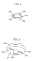
- the Oldham coupling ( 39 ) is a ring-shape member that is made from, for example, aluminum, and it is constituted such that a pair of orbiting-scroll-side keys ( 39a , 39a ) and a pair of housing-side keys ( 39b , 39b ) project respectively, as shown in FIG. 4 .
- the orbiting-scroll-side keys ( 39a,39a ) are formed at the obverse side of the Oldham coupling ( 39 ), while the housing-side keys ( 39b,39b ) are formed at the reverse side of the Oldham coupling ( 39 ) so as to be located at a position which has a 90° different phase from the orbiting-scroll-side keys ( 39a,39a ) to an axial center of the drive shaft ( 17 ).
- key grooves ( 26c,26c ) are formed at the back of the orbiting scroll ( 26 ), corresponding to the orbiting-scroll-side keys ( 39a,39a ). Further, as shown in the enlarged view of FIG. 3 , key grooves ( 23a,23a ) are formed at the obverse of the housing ( 23 ), corresponding to the housing-side keys ( 39b , 39b ). Then, two pair of key grooves ( 26c , 23a ) and the keys ( 39a , 39b ) are engaged with each other so as to constitute the Oldham coupling ( 39 ) that is capable of sliding in the first direction (lateral direction in FIG.
- a cylindrical boss ( 26d ) is formed so as to project at the center of a lower face of the end plate ( 26a ) of the orbiting scroll ( 26 ).
- the drive shaft ( 17 ) is provided with an eccentric-shaft portion ( 17a ) at its upper end.
- the eccentric-shaft portion ( 17a ) is inserted in the boss ( 26d ) of the orbiting scroll ( 26 ) through a sliding bearing ( 27 ) so as to rotate freely.
- the drive shaft ( 17 ) is provided with a counter weight (not shown in any drawing) at a lower-side portion of the radial bearing portion ( 32 ) of the housing ( 23 ) to keep a dynamic balance with the orbiting scroll ( 26 ), the eccentric-shaft portion ( 17a ) and the like.
- the drive shaft ( 17 ) rotates balancing weight by the counter weight.
- the Oldham coupling ( 39 ) slides reciprocatingly in the first direction to the fixed scroll ( 24 ) along the key grooves ( 23a,23a ) at the side of housing ( 23 ), and the orbiting scroll ( 26 ) slides reciprocatingly in the second direction to the Oldham coupling ( 39 ) along the key grooves ( 26c , 26c ).
- the orbiting scroll ( 26 ) just revolves orbitally to the fixed scroll ( 24 ) without rotating on its own axis.
- the compression chamber ( 40 ) between the both wraps ( 24b,26b ) contracts toward the center thereof with the revolution of the orbiting scroll ( 26 ), thereby compressing the refrigerant sucked through the suction pipe ( 19 ).
- the scroll compressor ( 15 ) is provided with a gas passage (not shown in any drawing) that is formed over the fixed scroll ( 24 ) and the housing ( 23 ) so as to connect the compression chamber ( 40 ) and the high-pressure space ( 18 ). Accordingly, the high-pressure refrigerant compressed in the compression chamber ( 40 ) is discharged from a discharge hole ( 41 ) that is formed at an end portion of the above gas passage (see FIG. 2 ) to the high-pressure space ( 18 ) through the gas passage, and then flows out of the discharge pipe ( 20 ) into the refrigerating circuit.
- a revolutionary position of the orbiting scroll ( 26 ) where the pressure of the refrigerant in the compression chamber ( 40 ) becomes the greatest (this revolutionary position corresponds substantially to a revolutionary position where a first rotational torque ( T1 ) by a reaction force of the refrigerant becomes the greatest) is located at about 90° (at the upper side of the center ( 01 ) of the fixed scroll ( 24 )) as shown in FIG. 2 , assuming that the revolutionary position is a standard (0°) when the center ( 02 ) of the orbiting scroll ( 26 ) is located at the right side of the center ( 01 ) of the fixed scroll ( 24 ) in FIG. 2 .
- the key grooves ( 23a , 23a ) at the side of the housing ( 23 ) are formed at positions of 0° and 180°, respectively. Also, the key grooves ( 26c , 26c ) at the side of the orbiting scroll are formed at positions that are perpendicular to the key grooves ( 23a,23a ) at the side of the housing ( 23 ), seeing from the center-line direction of the drive shaft ( 17 ), namely at positions of 90° and 270° in the drawing.
- the Oldham coupling ( 39 ) executes a reciprocating sliding-movement to the fixed scroll ( 24 ) along the key grooves ( 23a,23a ) at the side of the housing ( 23 ). Accordingly, the sliding direction (first direction) of the Oldham coupling ( 39 ) crosses the straight line that passes through the centers ( 01 , 02 ) of the both scrolls ( 24 , 26 ) at a state shown in FIG. 2 where the first rotational torque ( T1 ) becomes almost the greatest, at an angle of substantial 90° on a plane that is perpendicular to the axis of the drive shaft ( 17 ). An inertia force ( F0 ) of the Oldham coupling ( 39 ) becomes the greatest at its middle position of the reciprocating sliding-movement. Accordingly, in the above positional relationship, when the revolutionary position of the orbiting scroll ( 26 ) is at positions of 90° and 270°, the absolute value of the inertia force ( F0 ) becomes the greatest.
- the drive shaft ( 17 ) rotates with starting of the driving motor, and its driving power is conveyed to the orbiting scroll ( 26 ) of the scroll compressing mechanism ( 15 ).
- the eccentric-shaft portion ( 17a ) of the drive shaft ( 17 ) revolves on a certain revolutionary orbit, while the Oldham coupling ( 39 ) slides in the first direction to the fixed scroll ( 24 ) by the function of the key ( 391b ) and the key groove ( 23a ) and the orbiting scroll ( 26 ) slides in the second direction to the Oldham coupling ( 39 ) by the function of the key ( 39a ) and the key groove ( 26c ), and therefore the orbiting scroll ( 26 ) revolves orbitally without rotating on its own axis.
- a low-pressure gas refrigerant that has been evaporated at an evaporator in the refrigerating circuit not shown in any drawing is sucked into the compression chamber ( 40 ) from the peripheral-edge side of the compression chamber ( 40 ) through the suction pipe ( 19 ).
- the refrigerant is compressed and increases in pressure with changing of the displacement of the compression chamber ( 40 ) in the scroll compressing mechanism ( 15 ), and then it flows into the high-pressure space ( 18 ) through the discharge hole ( 41 ) and the gas passage.
- the refrigerant circulates in the refrigerating circuit and then is sucked again into the scroll compressor ( 1 ) through the suction pipe ( 19 ). This operation is repeated in the present embodiment.
- the above refrigerant's reaction force is comprised of a lateral-direction load and an axial-direction load.
- the function of the lateral-direction load ( FT ) is shown in FIG. 6 in simplified way. Assuming that the lateral-direction load ( FT ) acts on one point (hereinafter, referred to as acting point ( P1 )) on the straight line connecting the center ( 02 ) of the orbiting scroll ( 26 ) with the center ( 01 ) of the fixed scroll ( 24 ) as shown in this figure, the first rotational torque ( T1 ) by the refrigerant's reaction force is determined by multiplying the lateral-direction load ( FT ) by the distance between the center ( 01 ) of the fixed scroll ( 24 ) and the acting point ( P1 ).
- the first rotational torque ( T1 ) becomes the greatest at the revolutionary position where the reaction force of the refrigerant compressed in the compression chamber ( 40 ) during the orbital revolution of the orbiting scroll ( 24 ) becomes the greatest, and at this time the lateral-direction load ( FT ) acts in the direction that is substantially perpendicular to the straight line passing through the centers ( 01 , 02 ) of the fixed scroll ( 24 ) and the orbiting scroll ( 26 ).
- the rotational torque ( T ) of the orbiting scroll ( 26 ), as described above, is the sum of the first rotational torque ( T1 ) by the refrigerant's reaction force and moments by other aspects.
- defining the sliding direction (first direction) of the Oldham coupling ( 39 ), which is one of factors for the fluctuation, as described above makes the inertia force ( F0 ) act in the opposite direction to the lateral-direction load ( FT ) by the refrigerant's reaction force, result in suppressing a fluctuation of the total torque ( T ).
- the lateral-direction element ( FT ) by the refrigerant's reaction force with its greatest value acts on the orbiting scroll ( 26 ) in the right direction in FIG. 6
- the Oldham coupling ( 39 ) is under movement in the left direction in the figure along the key grooves ( 23a,23a ) at the side of the housing ( 23 ) with the orbital revolution of the orbiting scroll ( 26 ) and the inertia force ( F0 ) becomes the greatest at this time.
- the refrigerant's reaction force ( FT ) and the inertia force ( F0 ) act in the opposite directions to each other with their greatest value, they act so as to offset each other and thereby the maximum value of the total rotational torque ( T ) acting on the orbiting scroll ( 26 ) becomes small.
- the phase difference between the cyclic fluctuation of the first rotational torque ( T1 ) by the gas reaction force and the cyclic fluctuation of the second rotational torque ( T2 ) by the sliding movement of the Oldham coupling ( 39 ) becomes substantial 180° as shown later.
- the range of fluctuation of the total torque ( T ) of the first rotational torque ( T1 ) and the second rotational torque ( T2 ) is contracted so as to be smaller than that of the first rotational torque ( T1 ).
- the total rotational torque ( T ) acting on the orbiting scroll ( 26 ) is made stable, any force to turn the orbiting scroll ( 26 ) reversely does not occur easily, and any shaking between the keys ( 39a, 39b ) of the Oldham coupling ( 39 ) and the key grooves ( 26c,23a ) of the orbiting scroll and the housing does not occur easily either.
- the present embodiment is constituted such that the line connecting the center ( 02 ) of the orbiting scroll ( 26 ) with the center ( 01 ) of the fixed scroll ( 24 ) when the refrigerant's reaction force becomes the greatest crosses the first direction of sliding of the Oldham coupling ( 39 ) at an angle of 90°.
- the crossing angle may be changed in the present invention, as long as the range of fluctuation of the total rotational torque ( T ) becomes smaller than that of the first rotational torque ( T1 ).
- the positional angle of the two pair of keys ( 39a , 39b ) and the key grooves ( 26c , 23a ) are different from that of the above embodiment by 90°.
- the key grooves ( 26c , 26c ) of the orbiting scroll ( 26 ) are located at the positions which are equivalent to the revolutionary position of the orbiting scroll ( 26 ) of 0° and 180°, while the key grooves ( 23a , 23a ) at the side of the housing ( 23 ) are located at the positions equivalent to that of 90° and 270°.
- the orbiting scroll ( 26 ) is constituted such that the direction of the line connecting the center ( 02 ) of the orbiting scroll ( 26 ) with the center ( 01 ) of the fixed scroll ( 24 ) when the first rotational torque ( T1 ) by the refrigerant's compression becomes the greatest corresponds to the first direction of sliding of the Oldham coupling ( 39 ) (sliding direction to the fixed scroll ( 24 )).
- loads ( F1 - F4 ) show the loads occurring on respective orbiting-scroll-side keys ( 39a , 39a ) at 0°, 180° and respective housing-side keys ( 39b , 39b ) at 90° and 270°, in order.
- loads ( F1 - F4 ) having their negative values have a risk to reverse the rotational torque ( T ).
- the load ( F2 ) acting on the orbiting-scroll-side key ( 39a ) at the position of 180° in the above loads ( F1 - F4 ) is the one having the smallest value thereof, which is considered to have a high risk to reverse the rotational torque ( T ).
- the load ( F2 ) will be examined.
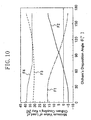
- FIG. 9 shows results.
- a state can be understood where the range of fluctuation of the load ( F2 ) enlarged with the speed increasing and the load ( F2 ) turned to a negative value at the revolutionary position of the orbiting scroll ( 26 ) of 270° especially after the speed exceeded 90 revolutions per second. Accordingly, there arises a high risk at this point that the acting direction of the rotational torque ( T ) reverses.
- the keys ( 39a , 39b ) of the Oldham coupling ( 39 ) hit one time at the key grooves ( 23a , 26c ) during one orbital revolution of the orbiting scroll ( 26 ), thereby causing noise and vibration of the scroll compressor ( 1 ).
- the load ( F1 ) became negative values in the range of the disposition angle ( ⁇ ) that is greater than 120°
- the load ( F2 ) became negative values in the range of the disposition angle ( ⁇ ) that is smaller than 60°. Accordingly, it can be considered that in a range excluding the above angles (range between 60° and 120°) the total torque ( T ) may not reverse and thereby the noise and vibration of the scroll compressor ( 1 ) can be suppressed because the loads have always their positive values therein.
- the disposition angle ( ⁇ ) of the keys ( 39a,39b ) should be set appropriately in a range that is 30° above and below the disposition angle of the above embodiment.
- the first direction of sliding of the Oldham coupling ( 39 ) should be set appropriately so as to cross the straight line that passes through the centers ( 01 , 02 ) of the fixed scroll ( 24 ) and the orbiting scroll ( 26 ) at the revolutionary position where the reaction force of the gas compressed in the compression chamber ( 40 ) between the both scrolls ( 24,26 ) becomes the greatest during the orbital revolution of the orbiting scroll ( 26 ), at an angle within 60° to 120° on the plane which is perpendicular to the rotational axial center of the drive shaft ( 17 ).
- the first direction at the position of 90° to the above straight line (position where the phase difference between respective fluctuation of the first rotational torque ( T1 ) and the second rotational torque ( T2 ) becomes 180°), and it is appropriate to set in a range that is 30° above and below the above position.
- the phase difference between the cyclic fluctuation of the first rotational torque ( T1 ) acting on the orbiting scroll ( 26 ) by the reaction force of the gas compressed in the compression chamber ( 40 ) during the orbital revolution of the orbiting scroll ( 26 ) and the cyclic fluctuation of the second rotational torque ( T2 ) by the sliding movement in the first direction of the Oldham coupling ( 39 ) becomes about a half of cycle (180° ⁇ 30°). Accordingly, the first rotational torque ( T1 ) and the second rotational torque ( T2 ) act so as to offset the fluctuation range of each other, and thereby reversing of the total rotational torque ( T ) can be prevented and the noise and vibration of the scroll compressor ( 1 ) can be suppressed.
- the present invention is useful for the scroll compressor.
Landscapes
- Engineering & Computer Science (AREA)
- Mechanical Engineering (AREA)
- General Engineering & Computer Science (AREA)
- Rotary Pumps (AREA)
- Applications Or Details Of Rotary Compressors (AREA)
Applications Claiming Priority (3)
| Application Number | Priority Date | Filing Date | Title |
|---|---|---|---|
| JP2002175429A JP3693041B2 (ja) | 2002-06-17 | 2002-06-17 | スクロール圧縮機 |
| JP2002175429 | 2002-06-17 | ||
| PCT/JP2003/005670 WO2003106843A1 (ja) | 2002-06-17 | 2003-05-06 | スクロール圧縮機 |
Publications (3)
| Publication Number | Publication Date |
|---|---|
| EP1515046A1 true EP1515046A1 (de) | 2005-03-16 |
| EP1515046A4 EP1515046A4 (de) | 2006-08-02 |
| EP1515046B1 EP1515046B1 (de) | 2014-12-24 |
Family
ID=29728034
Family Applications (1)
| Application Number | Title | Priority Date | Filing Date |
|---|---|---|---|
| EP03721033.3A Expired - Lifetime EP1515046B1 (de) | 2002-06-17 | 2003-05-06 | Methode für geräuschreduzierung eines kompressors der spiralbauart |
Country Status (10)
| Country | Link |
|---|---|
| US (1) | US6939116B2 (de) |
| EP (1) | EP1515046B1 (de) |
| JP (1) | JP3693041B2 (de) |
| KR (1) | KR100550777B1 (de) |
| CN (1) | CN1318759C (de) |
| AU (1) | AU2003235852B2 (de) |
| BR (1) | BR0305249B1 (de) |
| MY (1) | MY127790A (de) |
| TW (1) | TWI223688B (de) |
| WO (1) | WO2003106843A1 (de) |
Families Citing this family (7)
| Publication number | Priority date | Publication date | Assignee | Title |
|---|---|---|---|---|
| EP2628955A1 (de) | 2004-12-21 | 2013-08-21 | Daikin Industries, Ltd. | Scroll-Fluidmaschine |
| KR101371034B1 (ko) * | 2007-10-19 | 2014-03-10 | 엘지전자 주식회사 | 스크롤 압축기 |
| JP2010249130A (ja) * | 2009-03-27 | 2010-11-04 | Sanden Corp | 流体機械 |
| KR101059880B1 (ko) * | 2011-03-09 | 2011-08-29 | 엘지전자 주식회사 | 스크롤 압축기 |
| JP5999971B2 (ja) * | 2012-05-09 | 2016-09-28 | 三菱電機株式会社 | スクロール圧縮機 |
| JP7314302B2 (ja) * | 2019-04-08 | 2023-07-25 | 日立ジョンソンコントロールズ空調株式会社 | 共回転スクロール圧縮機におけるオルダム継手 |
| CN215890458U (zh) * | 2021-09-02 | 2022-02-22 | 丹佛斯(天津)有限公司 | 涡旋组件和涡旋压缩机 |
Family Cites Families (17)
| Publication number | Priority date | Publication date | Assignee | Title |
|---|---|---|---|---|
| JPH0637875B2 (ja) * | 1985-07-16 | 1994-05-18 | 三菱電機株式会社 | スクロ−ル圧縮機 |
| JPH0647990B2 (ja) * | 1987-08-21 | 1994-06-22 | 株式会社日立製作所 | スクロ−ル圧縮機 |
| JP3127568B2 (ja) | 1992-05-08 | 2001-01-29 | ダイキン工業株式会社 | スクロール型流体装置 |
| JPH0637875A (ja) * | 1992-07-16 | 1994-02-10 | Fujitsu Ltd | 通信端末装置保持台 |
| US5318424A (en) * | 1992-12-07 | 1994-06-07 | Carrier Corporation | Minimum diameter scroll component |
| JPH0791380A (ja) * | 1993-09-22 | 1995-04-04 | Mitsubishi Electric Corp | スクロール圧縮機 |
| JPH07269478A (ja) * | 1994-03-31 | 1995-10-17 | Toshiba Corp | 流体圧縮機 |
| JP3635794B2 (ja) * | 1996-07-22 | 2005-04-06 | 松下電器産業株式会社 | スクロール気体圧縮機 |
| US5836752A (en) * | 1996-10-18 | 1998-11-17 | Sanden International (U.S.A.), Inc. | Scroll-type compressor with spirals of varying pitch |
| JP3575201B2 (ja) * | 1996-12-25 | 2004-10-13 | ダイキン工業株式会社 | スクロール形流体機械 |
| JP3498535B2 (ja) * | 1997-06-03 | 2004-02-16 | 松下電器産業株式会社 | スクロール圧縮機 |
| WO1999063227A1 (en) | 1997-06-03 | 1999-12-09 | Matsushita Electric Industrial Co., Ltd. | Scroll compressor |
| JP3865478B2 (ja) * | 1997-08-29 | 2007-01-10 | サンデン株式会社 | スクロール型圧縮機 |
| US6478556B2 (en) * | 1999-12-24 | 2002-11-12 | Lg Electronics Inc. | Asymmetric scroll compressor |
| JP2001221169A (ja) * | 2000-09-09 | 2001-08-17 | 哲哉 ▲荒▼田 | 複数連結式スクロール圧縮機 |
| CN1164871C (zh) * | 2000-10-23 | 2004-09-01 | Lg电子株式会社 | 涡卷压缩机 |
| US6736622B1 (en) * | 2003-05-28 | 2004-05-18 | Scroll Technologies | Scroll compressor with offset scroll members |
-
2002
- 2002-06-17 JP JP2002175429A patent/JP3693041B2/ja not_active Expired - Fee Related
-
2003
- 2003-05-06 BR BRPI0305249-4A patent/BR0305249B1/pt not_active IP Right Cessation
- 2003-05-06 KR KR1020047010877A patent/KR100550777B1/ko not_active Expired - Fee Related
- 2003-05-06 EP EP03721033.3A patent/EP1515046B1/de not_active Expired - Lifetime
- 2003-05-06 US US10/495,547 patent/US6939116B2/en not_active Expired - Lifetime
- 2003-05-06 CN CNB038013053A patent/CN1318759C/zh not_active Expired - Fee Related
- 2003-05-06 AU AU2003235852A patent/AU2003235852B2/en not_active Ceased
- 2003-05-06 WO PCT/JP2003/005670 patent/WO2003106843A1/ja not_active Ceased
- 2003-06-16 MY MYPI20032244A patent/MY127790A/en unknown
- 2003-06-17 TW TW092116407A patent/TWI223688B/zh not_active IP Right Cessation
Non-Patent Citations (2)
| Title |
|---|
| No further relevant documents disclosed * |
| See also references of WO03106843A1 * |
Also Published As
| Publication number | Publication date |
|---|---|
| WO2003106843A1 (ja) | 2003-12-24 |
| AU2003235852B2 (en) | 2005-09-08 |
| US20050112011A1 (en) | 2005-05-26 |
| EP1515046A4 (de) | 2006-08-02 |
| BR0305249B1 (pt) | 2012-04-17 |
| TW200404957A (en) | 2004-04-01 |
| AU2003235852A1 (en) | 2003-12-31 |
| KR100550777B1 (ko) | 2006-02-08 |
| MY127790A (en) | 2006-12-29 |
| TWI223688B (en) | 2004-11-11 |
| CN1571887A (zh) | 2005-01-26 |
| CN1318759C (zh) | 2007-05-30 |
| JP3693041B2 (ja) | 2005-09-07 |
| JP2004019545A (ja) | 2004-01-22 |
| BR0305249A (pt) | 2004-09-21 |
| EP1515046B1 (de) | 2014-12-24 |
| KR20040111345A (ko) | 2004-12-31 |
| US6939116B2 (en) | 2005-09-06 |
Similar Documents
| Publication | Publication Date | Title |
|---|---|---|
| JP5386219B2 (ja) | スクロール圧縮機 | |
| KR20060020640A (ko) | 오프셋 스크롤 부재를 구비한 스크롤 압축기 | |
| EP1515046B1 (de) | Methode für geräuschreduzierung eines kompressors der spiralbauart | |
| WO1999039104A1 (fr) | Compresseur a cylindree variable | |
| US8734142B2 (en) | Rotation preventing member of a scroll compressor | |
| JP2897449B2 (ja) | スクロール圧縮機の可変クランク機構 | |
| KR20200132421A (ko) | 스크롤형 압축기 | |
| CN111749885B (zh) | 涡旋型压缩机 | |
| JP5295087B2 (ja) | スクロール圧縮機 | |
| US10920775B2 (en) | Scroll compressor with different sized gaps formed between inner and outer peripheral surfaces of scroll laps | |
| KR100343733B1 (ko) | 스크롤 압축기의 반경 방향 실링장치 | |
| WO2005068841A1 (ja) | スクロール流体機械 | |
| KR102538615B1 (ko) | 전동압축기의 회전자 조립구조 | |
| KR102481673B1 (ko) | 스크롤 압축기 | |
| KR100633168B1 (ko) | 스크롤 압축기 | |
| JPH09296786A (ja) | スクロール圧縮機 | |
| JP5999971B2 (ja) | スクロール圧縮機 | |
| WO2024257372A1 (ja) | スクロール圧縮機 | |
| JPH07151073A (ja) | スクロール型流体装置 | |
| GB2620055A (en) | Two-stage scroll compressor | |
| JPH04219401A (ja) | スクロール流体機械 | |
| JPH0343690A (ja) | スクロール型流体装置 | |
| JPH062672A (ja) | スクロール式流体機械 | |
| JPH04219402A (ja) | スクロール流体機械 | |
| JP2002180979A (ja) | スクロール型圧縮機およびガス圧縮方法 |
Legal Events
| Date | Code | Title | Description |
|---|---|---|---|
| PUAI | Public reference made under article 153(3) epc to a published international application that has entered the european phase |
Free format text: ORIGINAL CODE: 0009012 |
|
| 17P | Request for examination filed |
Effective date: 20040421 |
|
| AK | Designated contracting states |
Kind code of ref document: A1 Designated state(s): AT BE BG CH CY CZ DE DK EE ES FI FR GB GR HU IE IT LI LU MC NL PT RO SE SI SK TR |
|
| A4 | Supplementary search report drawn up and despatched |
Effective date: 20060630 |
|
| 17Q | First examination report despatched |
Effective date: 20070326 |
|
| GRAP | Despatch of communication of intention to grant a patent |
Free format text: ORIGINAL CODE: EPIDOSNIGR1 |
|
| INTG | Intention to grant announced |
Effective date: 20140730 |
|
| GRAS | Grant fee paid |
Free format text: ORIGINAL CODE: EPIDOSNIGR3 |
|
| GRAA | (expected) grant |
Free format text: ORIGINAL CODE: 0009210 |
|
| AK | Designated contracting states |
Kind code of ref document: B1 Designated state(s): AT BE BG CH CY CZ DE DK EE ES FI FR GB GR HU IE IT LI LU MC NL PT RO SE SI SK TR |
|
| REG | Reference to a national code |
Ref country code: GB Ref legal event code: FG4D |
|
| REG | Reference to a national code |
Ref country code: CH Ref legal event code: EP |
|
| REG | Reference to a national code |
Ref country code: IE Ref legal event code: FG4D |
|
| REG | Reference to a national code |
Ref country code: AT Ref legal event code: REF Ref document number: 703298 Country of ref document: AT Kind code of ref document: T Effective date: 20150115 |
|
| REG | Reference to a national code |
Ref country code: DE Ref legal event code: R096 Ref document number: 60347133 Country of ref document: DE Effective date: 20150219 |
|
| REG | Reference to a national code |
Ref country code: NL Ref legal event code: VDEP Effective date: 20141224 |
|
| PG25 | Lapsed in a contracting state [announced via postgrant information from national office to epo] |
Ref country code: FI Free format text: LAPSE BECAUSE OF FAILURE TO SUBMIT A TRANSLATION OF THE DESCRIPTION OR TO PAY THE FEE WITHIN THE PRESCRIBED TIME-LIMIT Effective date: 20141224 |
|
| PG25 | Lapsed in a contracting state [announced via postgrant information from national office to epo] |
Ref country code: SE Free format text: LAPSE BECAUSE OF FAILURE TO SUBMIT A TRANSLATION OF THE DESCRIPTION OR TO PAY THE FEE WITHIN THE PRESCRIBED TIME-LIMIT Effective date: 20141224 Ref country code: GR Free format text: LAPSE BECAUSE OF FAILURE TO SUBMIT A TRANSLATION OF THE DESCRIPTION OR TO PAY THE FEE WITHIN THE PRESCRIBED TIME-LIMIT Effective date: 20150325 |
|
| REG | Reference to a national code |
Ref country code: AT Ref legal event code: MK05 Ref document number: 703298 Country of ref document: AT Kind code of ref document: T Effective date: 20141224 |
|
| PG25 | Lapsed in a contracting state [announced via postgrant information from national office to epo] |
Ref country code: NL Free format text: LAPSE BECAUSE OF FAILURE TO SUBMIT A TRANSLATION OF THE DESCRIPTION OR TO PAY THE FEE WITHIN THE PRESCRIBED TIME-LIMIT Effective date: 20141224 |
|
| PG25 | Lapsed in a contracting state [announced via postgrant information from national office to epo] |
Ref country code: SK Free format text: LAPSE BECAUSE OF FAILURE TO SUBMIT A TRANSLATION OF THE DESCRIPTION OR TO PAY THE FEE WITHIN THE PRESCRIBED TIME-LIMIT Effective date: 20141224 Ref country code: RO Free format text: LAPSE BECAUSE OF FAILURE TO SUBMIT A TRANSLATION OF THE DESCRIPTION OR TO PAY THE FEE WITHIN THE PRESCRIBED TIME-LIMIT Effective date: 20141224 Ref country code: EE Free format text: LAPSE BECAUSE OF FAILURE TO SUBMIT A TRANSLATION OF THE DESCRIPTION OR TO PAY THE FEE WITHIN THE PRESCRIBED TIME-LIMIT Effective date: 20141224 Ref country code: CZ Free format text: LAPSE BECAUSE OF FAILURE TO SUBMIT A TRANSLATION OF THE DESCRIPTION OR TO PAY THE FEE WITHIN THE PRESCRIBED TIME-LIMIT Effective date: 20141224 Ref country code: ES Free format text: LAPSE BECAUSE OF FAILURE TO SUBMIT A TRANSLATION OF THE DESCRIPTION OR TO PAY THE FEE WITHIN THE PRESCRIBED TIME-LIMIT Effective date: 20141224 |
|
| PG25 | Lapsed in a contracting state [announced via postgrant information from national office to epo] |
Ref country code: AT Free format text: LAPSE BECAUSE OF FAILURE TO SUBMIT A TRANSLATION OF THE DESCRIPTION OR TO PAY THE FEE WITHIN THE PRESCRIBED TIME-LIMIT Effective date: 20141224 |
|
| REG | Reference to a national code |
Ref country code: DE Ref legal event code: R097 Ref document number: 60347133 Country of ref document: DE |
|
| PG25 | Lapsed in a contracting state [announced via postgrant information from national office to epo] |
Ref country code: DK Free format text: LAPSE BECAUSE OF FAILURE TO SUBMIT A TRANSLATION OF THE DESCRIPTION OR TO PAY THE FEE WITHIN THE PRESCRIBED TIME-LIMIT Effective date: 20141224 |
|
| PLBE | No opposition filed within time limit |
Free format text: ORIGINAL CODE: 0009261 |
|
| STAA | Information on the status of an ep patent application or granted ep patent |
Free format text: STATUS: NO OPPOSITION FILED WITHIN TIME LIMIT |
|
| 26N | No opposition filed |
Effective date: 20150925 |
|
| REG | Reference to a national code |
Ref country code: CH Ref legal event code: PL |
|
| PG25 | Lapsed in a contracting state [announced via postgrant information from national office to epo] |
Ref country code: MC Free format text: LAPSE BECAUSE OF FAILURE TO SUBMIT A TRANSLATION OF THE DESCRIPTION OR TO PAY THE FEE WITHIN THE PRESCRIBED TIME-LIMIT Effective date: 20141224 Ref country code: LU Free format text: LAPSE BECAUSE OF FAILURE TO SUBMIT A TRANSLATION OF THE DESCRIPTION OR TO PAY THE FEE WITHIN THE PRESCRIBED TIME-LIMIT Effective date: 20150506 Ref country code: CH Free format text: LAPSE BECAUSE OF NON-PAYMENT OF DUE FEES Effective date: 20150531 Ref country code: LI Free format text: LAPSE BECAUSE OF NON-PAYMENT OF DUE FEES Effective date: 20150531 |
|
| REG | Reference to a national code |
Ref country code: IE Ref legal event code: MM4A |
|
| PG25 | Lapsed in a contracting state [announced via postgrant information from national office to epo] |
Ref country code: SI Free format text: LAPSE BECAUSE OF FAILURE TO SUBMIT A TRANSLATION OF THE DESCRIPTION OR TO PAY THE FEE WITHIN THE PRESCRIBED TIME-LIMIT Effective date: 20141224 |
|
| REG | Reference to a national code |
Ref country code: FR Ref legal event code: PLFP Year of fee payment: 14 |
|
| PG25 | Lapsed in a contracting state [announced via postgrant information from national office to epo] |
Ref country code: IE Free format text: LAPSE BECAUSE OF NON-PAYMENT OF DUE FEES Effective date: 20150506 |
|
| PG25 | Lapsed in a contracting state [announced via postgrant information from national office to epo] |
Ref country code: BE Free format text: LAPSE BECAUSE OF FAILURE TO SUBMIT A TRANSLATION OF THE DESCRIPTION OR TO PAY THE FEE WITHIN THE PRESCRIBED TIME-LIMIT Effective date: 20141224 |
|
| REG | Reference to a national code |
Ref country code: FR Ref legal event code: PLFP Year of fee payment: 15 |
|
| PG25 | Lapsed in a contracting state [announced via postgrant information from national office to epo] |
Ref country code: BG Free format text: LAPSE BECAUSE OF FAILURE TO SUBMIT A TRANSLATION OF THE DESCRIPTION OR TO PAY THE FEE WITHIN THE PRESCRIBED TIME-LIMIT Effective date: 20141224 Ref country code: HU Free format text: LAPSE BECAUSE OF FAILURE TO SUBMIT A TRANSLATION OF THE DESCRIPTION OR TO PAY THE FEE WITHIN THE PRESCRIBED TIME-LIMIT; INVALID AB INITIO Effective date: 20030506 |
|
| PG25 | Lapsed in a contracting state [announced via postgrant information from national office to epo] |
Ref country code: CY Free format text: LAPSE BECAUSE OF FAILURE TO SUBMIT A TRANSLATION OF THE DESCRIPTION OR TO PAY THE FEE WITHIN THE PRESCRIBED TIME-LIMIT Effective date: 20141224 |
|
| PG25 | Lapsed in a contracting state [announced via postgrant information from national office to epo] |
Ref country code: PT Free format text: LAPSE BECAUSE OF FAILURE TO SUBMIT A TRANSLATION OF THE DESCRIPTION OR TO PAY THE FEE WITHIN THE PRESCRIBED TIME-LIMIT Effective date: 20150424 |
|
| PG25 | Lapsed in a contracting state [announced via postgrant information from national office to epo] |
Ref country code: TR Free format text: LAPSE BECAUSE OF FAILURE TO SUBMIT A TRANSLATION OF THE DESCRIPTION OR TO PAY THE FEE WITHIN THE PRESCRIBED TIME-LIMIT Effective date: 20141224 |
|
| REG | Reference to a national code |
Ref country code: FR Ref legal event code: PLFP Year of fee payment: 16 |
|
| PGFP | Annual fee paid to national office [announced via postgrant information from national office to epo] |
Ref country code: IT Payment date: 20220412 Year of fee payment: 20 Ref country code: GB Payment date: 20220401 Year of fee payment: 20 Ref country code: FR Payment date: 20220408 Year of fee payment: 20 Ref country code: DE Payment date: 20220329 Year of fee payment: 20 |
|
| REG | Reference to a national code |
Ref country code: DE Ref legal event code: R071 Ref document number: 60347133 Country of ref document: DE |
|
| REG | Reference to a national code |
Ref country code: GB Ref legal event code: PE20 Expiry date: 20230505 |
|
| P01 | Opt-out of the competence of the unified patent court (upc) registered |
Effective date: 20230525 |
|
| PG25 | Lapsed in a contracting state [announced via postgrant information from national office to epo] |
Ref country code: GB Free format text: LAPSE BECAUSE OF EXPIRATION OF PROTECTION Effective date: 20230505 |