EP1514636A1 - Vorrichtung zur bearbeitung einer innenwandfläche eines tankturms und diese verwendendes verfahren zur bearbeitung einer innenwandfläche - Google Patents
Vorrichtung zur bearbeitung einer innenwandfläche eines tankturms und diese verwendendes verfahren zur bearbeitung einer innenwandfläche Download PDFInfo
- Publication number
- EP1514636A1 EP1514636A1 EP03721082A EP03721082A EP1514636A1 EP 1514636 A1 EP1514636 A1 EP 1514636A1 EP 03721082 A EP03721082 A EP 03721082A EP 03721082 A EP03721082 A EP 03721082A EP 1514636 A1 EP1514636 A1 EP 1514636A1
- Authority
- EP
- European Patent Office
- Prior art keywords
- operations
- wall surface
- welding
- digester
- tower structure
- Prior art date
- Legal status (The legal status is an assumption and is not a legal conclusion. Google has not performed a legal analysis and makes no representation as to the accuracy of the status listed.)
- Withdrawn
Links
- 238000000034 method Methods 0.000 title claims description 28
- 238000003466 welding Methods 0.000 claims abstract description 138
- 239000000725 suspension Substances 0.000 claims abstract description 41
- 230000007246 mechanism Effects 0.000 claims abstract description 23
- 230000006870 function Effects 0.000 claims description 10
- 238000007689 inspection Methods 0.000 claims description 9
- 238000004140 cleaning Methods 0.000 claims description 8
- 230000004048 modification Effects 0.000 claims description 8
- 238000012986 modification Methods 0.000 claims description 8
- 230000004075 alteration Effects 0.000 claims description 4
- 238000010276 construction Methods 0.000 abstract description 5
- 239000011324 bead Substances 0.000 description 14
- 239000000463 material Substances 0.000 description 12
- 230000000694 effects Effects 0.000 description 9
- 230000008439 repair process Effects 0.000 description 9
- CURLTUGMZLYLDI-UHFFFAOYSA-N Carbon dioxide Chemical compound O=C=O CURLTUGMZLYLDI-UHFFFAOYSA-N 0.000 description 6
- 230000009471 action Effects 0.000 description 6
- 230000007797 corrosion Effects 0.000 description 6
- 238000005260 corrosion Methods 0.000 description 6
- 229910000831 Steel Inorganic materials 0.000 description 5
- 238000005336 cracking Methods 0.000 description 5
- 239000010959 steel Substances 0.000 description 5
- 230000007547 defect Effects 0.000 description 4
- 238000005304 joining Methods 0.000 description 4
- 230000002035 prolonged effect Effects 0.000 description 4
- 230000009467 reduction Effects 0.000 description 4
- 238000005299 abrasion Methods 0.000 description 3
- 229910002092 carbon dioxide Inorganic materials 0.000 description 3
- 239000001569 carbon dioxide Substances 0.000 description 3
- 230000002950 deficient Effects 0.000 description 3
- 238000009408 flooring Methods 0.000 description 3
- 230000006872 improvement Effects 0.000 description 3
- 238000004519 manufacturing process Methods 0.000 description 3
- 239000010953 base metal Substances 0.000 description 2
- 238000006243 chemical reaction Methods 0.000 description 2
- 238000005253 cladding Methods 0.000 description 2
- 238000013461 design Methods 0.000 description 2
- 238000011161 development Methods 0.000 description 2
- 230000018109 developmental process Effects 0.000 description 2
- 238000009434 installation Methods 0.000 description 2
- 238000000465 moulding Methods 0.000 description 2
- 238000003908 quality control method Methods 0.000 description 2
- 238000009423 ventilation Methods 0.000 description 2
- 230000004323 axial length Effects 0.000 description 1
- 230000008859 change Effects 0.000 description 1
- 230000003247 decreasing effect Effects 0.000 description 1
- 230000006866 deterioration Effects 0.000 description 1
- 238000010586 diagram Methods 0.000 description 1
- 230000029087 digestion Effects 0.000 description 1
- 238000004090 dissolution Methods 0.000 description 1
- 238000010438 heat treatment Methods 0.000 description 1
- 230000003993 interaction Effects 0.000 description 1
- 238000011017 operating method Methods 0.000 description 1
- 230000035515 penetration Effects 0.000 description 1
- 230000002265 prevention Effects 0.000 description 1
- 230000008569 process Effects 0.000 description 1
- 230000001105 regulatory effect Effects 0.000 description 1
- 230000000717 retained effect Effects 0.000 description 1
- 230000002441 reversible effect Effects 0.000 description 1
- 238000004904 shortening Methods 0.000 description 1
- 238000003860 storage Methods 0.000 description 1
- 239000000126 substance Substances 0.000 description 1
- 238000004804 winding Methods 0.000 description 1
Images




Classifications
-
- E—FIXED CONSTRUCTIONS
- E04—BUILDING
- E04G—SCAFFOLDING; FORMS; SHUTTERING; BUILDING IMPLEMENTS OR AIDS, OR THEIR USE; HANDLING BUILDING MATERIALS ON THE SITE; REPAIRING, BREAKING-UP OR OTHER WORK ON EXISTING BUILDINGS
- E04G3/00—Scaffolds essentially supported by building constructions, e.g. adjustable in height
- E04G3/28—Mobile scaffolds; Scaffolds with mobile platforms
-
- D—TEXTILES; PAPER
- D21—PAPER-MAKING; PRODUCTION OF CELLULOSE
- D21C—PRODUCTION OF CELLULOSE BY REMOVING NON-CELLULOSE SUBSTANCES FROM CELLULOSE-CONTAINING MATERIALS; REGENERATION OF PULPING LIQUORS; APPARATUS THEREFOR
- D21C7/00—Digesters
-
- E—FIXED CONSTRUCTIONS
- E04—BUILDING
- E04G—SCAFFOLDING; FORMS; SHUTTERING; BUILDING IMPLEMENTS OR AIDS, OR THEIR USE; HANDLING BUILDING MATERIALS ON THE SITE; REPAIRING, BREAKING-UP OR OTHER WORK ON EXISTING BUILDINGS
- E04G1/00—Scaffolds primarily resting on the ground
- E04G1/18—Scaffolds primarily resting on the ground adjustable in height
- E04G1/20—Scaffolds comprising upright members and provision for supporting cross-members or platforms at different positions therealong
-
- E—FIXED CONSTRUCTIONS
- E04—BUILDING
- E04G—SCAFFOLDING; FORMS; SHUTTERING; BUILDING IMPLEMENTS OR AIDS, OR THEIR USE; HANDLING BUILDING MATERIALS ON THE SITE; REPAIRING, BREAKING-UP OR OTHER WORK ON EXISTING BUILDINGS
- E04G1/00—Scaffolds primarily resting on the ground
- E04G1/36—Scaffolds for particular parts of buildings or buildings of particular shape, e.g. for stairs, cupolas, domes
-
- E—FIXED CONSTRUCTIONS
- E04—BUILDING
- E04G—SCAFFOLDING; FORMS; SHUTTERING; BUILDING IMPLEMENTS OR AIDS, OR THEIR USE; HANDLING BUILDING MATERIALS ON THE SITE; REPAIRING, BREAKING-UP OR OTHER WORK ON EXISTING BUILDINGS
- E04G1/00—Scaffolds primarily resting on the ground
- E04G1/36—Scaffolds for particular parts of buildings or buildings of particular shape, e.g. for stairs, cupolas, domes
- E04G1/362—Scaffolds for particular parts of buildings or buildings of particular shape, e.g. for stairs, cupolas, domes specially adapted for tanks, silos or similar vessels
-
- E—FIXED CONSTRUCTIONS
- E04—BUILDING
- E04G—SCAFFOLDING; FORMS; SHUTTERING; BUILDING IMPLEMENTS OR AIDS, OR THEIR USE; HANDLING BUILDING MATERIALS ON THE SITE; REPAIRING, BREAKING-UP OR OTHER WORK ON EXISTING BUILDINGS
- E04G3/00—Scaffolds essentially supported by building constructions, e.g. adjustable in height
- E04G3/24—Scaffolds essentially supported by building constructions, e.g. adjustable in height specially adapted for particular parts of buildings or for buildings of particular shape, e.g. chimney stacks or pylons
-
- E—FIXED CONSTRUCTIONS
- E04—BUILDING
- E04G—SCAFFOLDING; FORMS; SHUTTERING; BUILDING IMPLEMENTS OR AIDS, OR THEIR USE; HANDLING BUILDING MATERIALS ON THE SITE; REPAIRING, BREAKING-UP OR OTHER WORK ON EXISTING BUILDINGS
- E04G3/00—Scaffolds essentially supported by building constructions, e.g. adjustable in height
- E04G3/24—Scaffolds essentially supported by building constructions, e.g. adjustable in height specially adapted for particular parts of buildings or for buildings of particular shape, e.g. chimney stacks or pylons
- E04G3/246—Scaffolds essentially supported by building constructions, e.g. adjustable in height specially adapted for particular parts of buildings or for buildings of particular shape, e.g. chimney stacks or pylons following the inside contour of a building
-
- E—FIXED CONSTRUCTIONS
- E04—BUILDING
- E04G—SCAFFOLDING; FORMS; SHUTTERING; BUILDING IMPLEMENTS OR AIDS, OR THEIR USE; HANDLING BUILDING MATERIALS ON THE SITE; REPAIRING, BREAKING-UP OR OTHER WORK ON EXISTING BUILDINGS
- E04G3/00—Scaffolds essentially supported by building constructions, e.g. adjustable in height
- E04G3/28—Mobile scaffolds; Scaffolds with mobile platforms
- E04G3/30—Mobile scaffolds; Scaffolds with mobile platforms suspended by flexible supporting elements, e.g. cables
Definitions
- the present invention relates to an operations apparatus for performing a variety of operations on an inner wall surface of a tower structure, and an operational method that uses such an operations apparatus.
- the invention relates to an operations apparatus and an operations method for performing welding operations on the inner wall surface of a tall tower structure used under conditions of high pressure and high temperature.
- Operations on the inner wall surface of a tower structure include welding, inspections, modifications, and cleaning, and welding operations have been the most needful of improvements in terms of continuity of the operation, danger, and the welding system.
- the digester which is the pressure vessel with a blast furnace type construction that is used in pulp dissolution, is used under conditions of high temperature and high pressure, and in the type of environment that accompanies the chemical reaction between the contents and the chemicals used, and consequently, is specified in the safety standards as a type 1 pressure vessel.
- digesters must be maintained at the safety standard for a type 1 pressure vessel, and the thickness of the wall sections must not only meet a design thickness deemed necessary to ensure a strong design, but must also include an additional level of excess thickness to ensure a predetermined safety factor.
- overlay method for abrasion based thinning of the walls, one possible measure is an "overlay method" in which overlay welding is performed within those sections of reduced thickness to recover the thickness to its original value.
- An “overlay method” is a technique that is particularly effective for repairing any of the above problems, and is gaining attention as an ideal technique for prolonging the life of tower structures such as digesters.
- an object of the present invention is to provide an operations apparatus for the inner wall surface of a tower structure that enables various operations performed on the inner wall surface of the tower structure to be conducted in a safer operating environment, with good operability and good reliability, as well as an operational method that utilizes such an operations apparatus.
- a suspension support base is installed inside a tower structure, a suspended beam structure is suspended from the suspension support base in a manner that enables movement up and down, a welding unit is attached to the suspended beam structure via a guide mechanism in a manner that enables movement up and down, and/or left and right, and operations are performed on the inner wall surface of the tower structure using the operations unit.
- the height position within the tower structure of the operations unit attached to the suspended beam structure in other words, the height setting within the tower structure for the operational target region for the operations unit, can be easily altered, and compared with a conventional case where a scaffold is put up inside the tower structure, and the height of the scaffold has to be changed every time the operating height is altered, the operation for adjusting levels during operations is markedly easier, or even unnecessary, which provides an equivalent improvement in the safety and operability associated with all manner of operations.
- the operations unit is attached to the suspended beam structure via the aforementioned guide mechanism, allowing the operations unit to be moved up and down, and/or left and right, control of the required operations performed using the operations unit (for example in the case of welding operations, control of the width of the weld bead, the weld direction, or the spacing between adjacent weld beads) is far easier and more reliable than the case in which this control depends solely upon the actions and judgment of the operator, and as a result, a very uniform operation will be conducted over an entire required height region with excellent reliability, thereby ensuring an effective extension of the life of the tower structure.
- a second aspect of the present invention is the operations apparatus for the inner wall surface of a tower structure described above, wherein the aforementioned guide mechanism comprises an upper guide structure and a lower guide structure that are separated and oppose each other across the vertical direction, and a vertical guide structure, which extends between each of the guide structures and is disposed in the vertical direction, is able to move in a left and right direction along the upper and lower guide structures, and supports the aforementioned operations unit in a manner that enables up and down movement.
- an operations apparatus for the inner wall surface of a tower structure which has the type of structure described above, because the guide mechanism is a simple and low cost mechanism formed from the upper guide structure, the lower guide structure and the vertical guide structure, an inner wall surface operations apparatus that displays the effects of the first aspect of the present invention will be provided at lower cost, and this contributes to a reduction in operating costs.
- a third aspect of the present invention is the operations apparatus for the inner wall surface of a tower structure described above, wherein the aforementioned operations unit is equipped with at least welding, inspection, modification, and cleaning functions.
- an operations apparatus for the inner wall surface of a tower structure according to the third aspect of the present invention, the following characteristic effects will be achieved in addition to the effects provided by the first or second aspects of the invention. Namely, in this aspect of the invention, because the operations unit is equipped with at least welding, inspection, modification, and cleaning functions, these various operations on the inner wall surface of the tower structure can be performed conjointly, and all of the operations will be performed highly efficiently with a high level of reliability.
- a fourth aspect of the present invention is the operations apparatus for the inner wall surface of a tower structure described above, wherein a post is set up in a vertical direction inside the tower structure, and a height adjustable operations platform is installed that can be raised and lowered under its own power in the vertical direction along this post.
- the following characteristic effects will be achieved in addition to the aforementioned effects provided by the first, second or third aspect of the invention.
- a post is set up in the vertical direction inside the tower structure, and a height adjustable operations platform is installed that can be raised and lowered under its own power in the vertical direction along this post, by raising and lowering the height adjustable operations platform under its own power in the vertical direction along the post, the height adjustable operations platform can be used to move operating materials or operators safely and rapidly to the operating position for the operations unit, without requiring any scaffold height adjustments, even if the tower structure is a blast furnace type structure of considerable height.
- both operational speed and safety are achieved, which leads to a reduction in the overall operational costs associated with the inner wall surface operations apparatus.
- a fifth aspect of the present invention is the operations apparatus for the inner wall surface of a tower structure described above, wherein a fixed operations platform is attached to the post, the fixed vertical position of the fixed operations platform relative to the post can be set and altered, and alteration of the fixed position of the fixed operations platform is performed by raising or lowering the height adjustable operations platform.
- the following characteristic effects will be achieved in addition to the aforementioned effects provided by the fourth aspect of the invention. Namely, in this aspect of the invention, because the fixed vertical position, relative to the post, of the fixed operations platform attached to the post can be set and altered, by fixing the fixed operations platform at a height position corresponding with the operating position for the operations unit, an operator rides on the fixed operations platform, and easily and accurately conducts quality control of the operations performed by the operations unit, enabling operations to be conducted with even greater reliability.
- an operational method for an inner wall surface comprises the steps of installing a suspension support base inside a tower structure, suspending a suspended beam structure from the suspension support base in a manner that enables movement up and down, attaching an operations unit to the suspended beam structure via a guide mechanism in a manner that enables movement up and down, and/or left and right, and performing operations on the inner wall surface of the tower structure using the operations unit.
- a suspension support base is installed inside a tower structure, a suspended beam structure is suspended from the suspension support base in a manner that enables movement up and down, an operations unit is attached to the suspended beam structure via a guide mechanism in a manner that enables movement up and down, and/or left and right, and operations are performed on the inner wall surface of the tower structure using the operations unit, and consequently, by moving the suspended beam structure suspended below the suspension support base in an upward or downward direction, the height position within the tower structure of the operations unit attached to the suspended beam structure, in other words, the height setting within the tower structure for the operational target region for the operations unit, would be easily altered, and compared with a conventional case where a scaffold is erected inside the tower structure, and the height of the scaffold has to be changed every time the operating height is altered, the operation for adjusting levels during operations is markedly easier, or even unnecessary, and this enables an improvement in the safety and operability associated with all manner of operations.
- the operations unit is able to move up and down, and/or left and right, control of the operating status of operations performed using the operations unit is extremely simple and reliable, and a very uniform operation will be conducted over an entire required height region with excellent reliability.
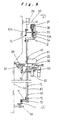
- FIG. 1 shows a digester 1 (tower structure), which is the pressure vessel of a blast furnace structure used in a paper production plant, with an overlay welding operations apparatus (inner wall surface operations apparatus) for conducting overlay welding on required areas of the inner wall surface of the digester 1 disposed therein.
- a digester 1 tower structure
- an overlay welding operations apparatus inner wall surface operations apparatus
- the digester 1 is, for example, a large scale, tall, closed vessel with an internal diameter of 4 to 5 meters and a height of 40 to 50 meters, and is classified as a type 1 pressure vessel in the safety standards. Accordingly, the thickness of the walls must be maintained above a defined constant thickness, and if the wall thickness is exposed to higher than expected abrasion, then in order to extend the life of the structure, a repair operation must be conducted to return the thickness to its original value, as described above.
- an "overlay method" is adopted as the method of repairing the wall surfaces of the digester 1, which involves extra thickness being attached to the inner wall surface using overlay welding, and the overlay welding operations apparatus described above is used for executing this overlay welding.
- the aforementioned digester 1 is formed as a sealed vessel, comprising a main body section 2 with a large diameter cylindrical structure, with a digester bottom structure 3 joined at one end and a digester top structure 4 joined at the other end, and is fixed in a vertical position with a bottom section 1a of the digester bottom structure 3 supported on a base 5.
- the main body section 2 is constructed so that the diameter dimension reduces in a stepwise manner from the bottom section 1a of the digester 1 through to a top section 1b, and a device such as a strainer (not shown in the drawing) is disposed in those regions where the diameter dimension reduces.
- an exhaust system 32 is attached to a bottom manhole 31 provided in a central position within the digester bottom structure 3, a large diameter manhole 35 provided substantially halfway up the digester is used as a natural air inlet, and additional exhaust systems 33, 34 are disposed at a pair of upper and lower manholes provided toward the top section 1b.
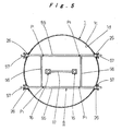
- a manhole 36 provided near the bottom section 1a of the digester 1 is used for introducing materials or allowing people to enter or exit from the digester 1, while a suspension support base 8, which is described below, is attached using four scaffold nozzles 26, 26, .. (see FIG. 5) provided directly below the manhole equipped with the exhaust system 34.
- the aforementioned overlay welding operations apparatus comprises a left and right pair of posts 16, 16 (described below) disposed in a parallel upright manner with a predetermined spacing therebetween, which extend between a lower fixed operations floor 6 (described below) that is disposed near the bottom section 1a of the digester 1, and an upper fixed operations floor 7 (described below) that is disposed toward the top section 1b, and a height adjustable operations platform 14 (described below) that can be raised and lowered under its own power, and a fixed operations platform 13 (described below) are attached to each of the posts 16, 16, a suspended beam structure 9 (described below) is suspended from the aforementioned suspension support base 8 (described below) in a manner that enables movement up and down, and a plurality of welding units 20 (which correspond with the "operations unit” disclosed in the claims) are attached to the suspended beam structure 9 via a guide mechanism Z (described below) in a manner that enables free movement up and down, and/or left and right (in a circumferential direction
- the posts 16 are formed from truss structured post pieces 16a, 16a,.. with a rectangular cross-section and a predetermined axial length, a predetermined number of which are joined together sequentially in an axial direction to form a column type structure.
- the posts 16, 16 are integrated together into an approximately ladder type structure by joint members 17, 17,.. that are attached to the posts at predetermined intervals along the axial direction, and by fixing the bottom end of the ladder structure to the lower fixed operations floor 6 that is described below (see FIG. 2) and fixing the top end to the upper fixed operations floor 7 that is described below (see FIG. 4), the posts 16, 16 are secured in a vertical direction inside the digester 1.
- the aforementioned posts 16 utilized two parallel columns separated by a predetermined spacing, and as described below, a guiding action and a support function for the fixed operations platform 13 and the height adjustable operations platform 14 is achieved through interaction with these two posts 16, 16, but the actual number of posts 16 installed in the present invention can be suitably increased or decreased as required, and in other embodiments, either a single post, or three or more parallel posts can be provided.
- the operational procedure used to set up a post 16 using the aforementioned post pieces 16a, 16a,.. is as follows. Namely, first the bottommost pair of posts 16, 16 are secured in an upright orientation at predetermined positions on top of the aforementioned lower fixed operations floor 6. Subsequently, the height adjustable operations platform 14 that is described below is assembled to correspond with each of these bottommost posts 16, 16, and is produced so as to be able to be raised and lowered under its own power. An operator and the aforementioned post pieces 16a, 16a,..
- the operation of setting up the posts 16 does not require the conventional type of prefabricated steel scaffold, and consequently, the operations associated with altering the height of the scaffold are unnecessary, which enables the operation of setting up the posts 16 to be completed safely and quickly.
- a rack 15 that functions as one portion of the height adjustment mechanism of the height adjustable operations platform 14 is provided on one side of each the posts 16, 16, and runs along the lengthwise direction of each post 16, 16.
- the post pieces 16a are carried into the digester 1 through the manhole 36, the post pieces must be set to a size and shape that enables passage through the manhole 36.
- the lower fixed operations floor 6 described above is secured in an intermediate position between the position immediately above the digester bottom structure 3 of the digester 1, and the position immediately below the manhole 36, and is used as an "operations platform" as per its original function, but also performs the important function of acting as a support base for the posts 16, 16.
- the lower fixed operations floor 6 is constructed by attaching four support girders 43, 43,.. in a cross girder arrangement, and then installing and fixing a flooring material 44 in a circular shape, the periphery of which extends out to a position close to, and facing the inner wall surface 1d of the side wall 1c, on top of these support girders 43, 43,... Then, the posts 16, 16 are secured by mounting the bottom ends of the posts 16, 16 (that is, the bottom end of the post piece 16a positioned at the bottommost end of each post 16) onto a left and right pair of support bases 41, 41 provided toward the center of the lower fixed operations floor 6, restricting the movement of the posts via positioning stoppers 42, 42,.. positioned at the outer periphery of the posts, and bolting the posts to the support bases via securing bolts (not shown in the drawing).
- the most characteristic feature of the lower fixed operations floor 6 is the construction used to secure each of the support girders 43, 43,.. to the digester 1. Namely, in this embodiment, as shown in FIG. 2 and FIG. 3, protruding securing pieces 45 are welded to the inner wall surface 1d of the side wall 1c at a position directly above the aforementioned digester bottom structure 3 of the digester 1, and each securing piece 45 and the end of a support girder 43 are secured together in a detachable manner via a connecting member 46. These securing pieces 45 are fixed around the periphery of the inner wall surface 1d with a predetermined spacing, so as to be positioned at each end of each of the four support girders 43, 43,.. respectively.
- the lower fixed operations floor 6 is attached to the bottom section 1a of the digester 1 via the securing pieces 45, 45,.., and by securing and supporting the posts 16, 16 on this lower fixed operations floor 6, the dead load of the posts 16, 16, the dead load of the fixed operations platform 13 and the height adjustable operations platform 14 described below, which are attached to the posts 16, 16, and the weight of the materials loaded onto each of these operations platforms 13, 14 are all transferred from the lower fixed operations floor 6, through the securing pieces 45, 45,.. and onto the side walls 1c of the digester 1, where they are safely supported.
- the aforementioned lower fixed operations floor 6 is the first structure set up when overlay welding operations are to be undertaken, and subsequent operations such as the transporting of various materials, and the assembling of the aforementioned posts 16, 16 or the height adjustable operations platform 14 are performed using this erected lower fixed operations floor 6 (in other words, it performs its primary function as an operations platform). Furthermore, because the lower fixed operations floor 6 is carried into and out of the digester 1 through the aforementioned manhole 36, each of the structural elements must be able to be disassembled down to a size capable of passing through the manhole 36 (not shown in the drawings).
- the upper fixed operations floor 7 described above is disposed at a position immediately below the digester top structure 4 of the digester 1 (see FIG. 1), has a circular, flat shape, and is positioned inside the side walls 1c of the digester 1 with a predetermined space retained between the floor and the side walls 1c.
- This upper fixed operations floor 7 is connected and secured to the top ends of the posts 16, 16 via a left and right pair of post securing members 50, 50 that are provided toward the center of the floor, while movement in the horizontal direction is regulated by bracing the tips of jacks 51, 51,.. provided at four locations around the outer periphery of the floor against the inner wall surface 1d of the side walls 1c.
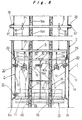
- the suspension support base 8 described above is disposed horizontally at a position toward the top section 1b of the digester 1, and supports the suspended guide mechanism Z described below, and as shown in FIG. 5 and FIG. 8, is constructed by inserting and engaging a girder member 55, via bearings 57, through a pair of scaffold nozzles 26, 26 formed in the side walls 1c of the digester 1 in opposing positions along an identical axis sitting to one side of the centerline of the digester, and through another pair of scaffold nozzles 26, 26 formed in opposing positions along an identical axis sitting to the other side of the centerline respectively, and then connecting this pair of girder members 55, 55 with joining members 56.
- the aforementioned posts 16, 16 pass vertically through the central section of this suspension support base 8, which is disposed horizontally across the inside of the digester 1.
- suspension positions P 1 , P 1 , .. are set at four positions near the connection points between each of the girder members 55, 55 and each of the joining members 56, 56 of the suspension support base 8. Then, as shown in FIG. 8, a chain block 18 is attached at each of these suspension positions P 1 , P 1 ,...
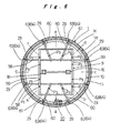
- the suspended beam structure 9 described above is suspended from and supported by the aforementioned suspension support base 8, via each of the aforementioned chain blocks 18, 18,.., and supports the suspended guide mechanism Z described below, and as shown in FIG. 6 and FIG. 8, is constructed by attaching to the top of a pair of girder members 58, 58 disposed in parallel with a predetermined spacing therebetween, a pair of girder members 59, 59 that sit orthogonally relative to the girder members 58, 58, thereby forming a cross girder arrangement, and then attaching a pair of girder members 61, 61 that extend between the end sections at both ends of the pair of girder members 59, 59, and attaching pairs of girder members 60, 60 that extend from the girder member 58 across the corresponding girder member 61 in a radial direction.
- suspension positions P 2 , P 2 ,.., each of which corresponds with one of the suspension positions P 1 , P 1 ,.. on the suspension support base 8, are set on top of the aforementioned pairs of girder members 59, 59, and the chains 19, 19,.. hanging down from each of the chain blocks 18 positioned at the suspension support base 8 are connected to each of these suspension positions P 2 , P 2 ,.., so that the suspended beam structure 9 is suspended from, and supported by the suspension support base 8 via these chains 19, 19,.., and can be raised or lowered vertically by winding each of the chains 19, 19, .. in, or back out.
- suspension positions P 3 , P 3 ,.. are set on the girder members 59, 59 containing the aforementioned suspension positions P 2 and on each of the girder members 60, 60, so as to be positioned on an identical circumference, with an identical pitch around the circumferential direction.
- Chain blocks 27, 27 are attached to each of these suspension positions P 3 , P 3 ,.., and a wire supply device 21 of a welding unit 20 described below is suspended via a chain 28 hanging down from each chain block 27, 27,...
- end sections of the aforementioned pair of girder members 58, 58 of the suspended beam structure 9, and the end sections of each of the girder members 60, 60 are positioned on an identical circumference, with a predetermined pitch around the circumferential direction. These end sections function as the suspension and support points for the guide mechanism Z described below, and a suspension link 29 is attached to each end section.
- the guide mechanism Z described above guides the movement of the welding units 20 described below, enabling good overlay welding to be conducted by the welding units 20, and comprises an upper guide structure 10, a lower guide structure 11, and a vertical guide structure 12, each of which is described below.
- the aforementioned upper guide structure 10 is constructed from an annular body (see FIG. 6) formed by curved molding of H-shaped steel (see FIG. 9), with the pair of flanges in a vertical arrangement, to enable the body to be positioned inside the inner wall surface 1d of the digester 1.
- This upper guide structure 10 is suspended from the suspended beam structure 9 via the aforementioned suspension links 29, 29,.., moves up and down in concert with the raising and lowering of the suspended beam structure 9, and as shown in FIG. 9, is supported against the inner wall surface 1d by bracing the tips of jacks 63, 63,.. that are attached to each of the suspension links 29, 29,.. against the inner wall surface 1d of the digester 1.
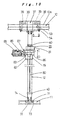
- the upper guide structure 10 guides the movements of the vertical guide structure 12 described below in the left and right directions (that is, the circumferential direction of the inner wall surface 1d) , and of the pair of flanges, the flange that is positioned on the inside in a radial direction is designed to function as a guide rail for the vertical guide structure 12, and consequently a saddle 37 for the vertical guide structure 12 is latched onto this inside flange (see FIG. 9 and FIG. 10).
- each of the structural elements must be able to be disassembled down to a size capable of passing through the manhole 36 (not shown in the drawings).
- the lower guide structure 11 described above is constructed from an annular body (see FIG. 6) formed by curved molding of L-shaped steel (see FIG. 9), with one of the flanges directed along the radial direction and the other flange directed upward, to enable the body to be positioned inside the inner wall surface 1d of the digester 1.
- This lower guide structure 11 is supported by the upper guide structure 10 via the vertical guide structure 12 that is described below, moves up and down when the upper guide structure 10 moves up and down in concert with the raising and lowering of the suspended beam structure 9, and as shown in FIG. 9, is supported against the inner wall surface 1d by bracing the tips of jacks 64, which are disposed with a predetermined spacing around the periphery of the lower guide structure 11, against the inner wall surface 1d of the digester 1.
- connection between the aforementioned lower guide structure 11 and the vertical guide structure 12 described below is achieved by sandwiching one flange section of the lower guide structure 11 between a fixed bracket 71, which is supported by a check bolt 72 that is inserted through a slotted hole 74 formed in a vertical direction in the bottom end section of the vertical guide structure 12, and a push bolt 73 that is attached to the vertical guide structure 12. Furthermore, by loosening the push bolt 73, loosening the check bolt 72 and moving the fixed bracket 71 upward, the connection between the lower guide structure 11 and the vertical guide structure 12 are released.
- the vertical guide structure 12 is constructed from a batten plate structure of a predetermined length, one end (the top end) of which is attached to the saddle 37 described below.
- the vertical guide structure 12 guides the up and down movements of the welding units 20 described below, and by moving the vertical guide structure 12 in the left and right directions under the guidance of the upper guide structure 10 and the lower guide structure 11, the welding units 20 are also movable in the left and right direction.
- the saddle 37 supports and suspends the vertical guide structure 12 from the upper guide structure 10, and enables the vertical guide structure 12 to be moved in the left and right directions along the upper guide structure 10, and as shown in FIG. 9 and FIG. 10, comprises a front and rear pair of slotted wheels 38, 38 that run along the top of the flange of the upper guide structure 10, and a front and rear pair of unslotted wheels 39, 39.
- the saddle 37 is also provided with a front and rear pair of check bolts 53, 53, which regulate the relative movement between the saddle 37 and the upper guide structure 10 by being screwed in until the tips of the bolts contact the upper guide structure 10, and a front and rear pair of lift prevention structures 54, 54, which are disposed so as to enable engagement against the bottom surface of the flange of the upper guide structure 10, and prevent the saddle 37 from lifting.
- the aforementioned vertical guide structure 12 is then secured so as to hang down from the saddle 37.
- the aforementioned check bolt 72 and the push bolt 73 are provided at the bottom end of the vertical guide structure 12, and by operating this check bolt 72 and push bolt 73, the bottom end section of the vertical guide structure 12 is connectable to, and releasable from, the lower guide structure 11, as described above.
- stoppers 40, 40 are provided at two vertical positions on the vertical guide structure 12, and a rack 80 is attached that extends between these two stoppers 40, 40. Then, a welding unit 20 that is described below is attached to the vertical guide structure 12, and can be raised and lowered along this rack 80.
- a plurality of vertical guide structures 12 constructed in the manner described above are disposed at predetermined intervals around the circumference of the upper guide structure 10.
- vertical guide structures 12 are disposed at eight positions, as shown by position a through position h in FIG. 6.
- the welding unit 20 described above comprises a carriage 79 that straddles the vertical guide structure 12 and is driven up and down along the rack 80 by the driving force from a motor 86, on which is mounted a welder main body 81, an oscillating device 82, a profiling device 83, a pair of welding torches 85, 85, and a profile detector 87.
- the welder main body 81 is a device that automatically performs arc shielded welding in a carbon dioxide gas atmosphere ("MAG welding"), and the two welding torches 85, 85 are connected in parallel to the welder main body 81 with a predetermined spacing therebetween.
- MAG welding carbon dioxide gas atmosphere
- eight sets of vertical guide structures 12 are provided, and two welding torches 85, 85 are mounted onto each of these vertical guide structures 12, and consequently overlay welding is performed with a total of 16 welding torches 85 being used concurrently.
- Each of the welding units 20 is also equipped with the aforementioned wire supply device 21 that supplies wire to the two welding torches 85 belonging to that particular unit, and as described above, this wire supply device 21 is suspended from the suspended beam structure 9 via the aforementioned chain block 27 in a manner that enables the supply device to be raised and lowered. Furthermore, a hose 57 (see FIG. 8) for supplying the shield gas to the welding torches 85 is also connected to the welding torches 85 via the wire supply device 21.
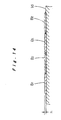
- the aforementioned welding units 20 are used to perform overlay welding on the inner wall surface 1d of the digester 1 by "vertical downward welding, " and the state of the weld beads in this type of overlay welding is shown in FIG. 13.
- overlay welding is conducted by “vertical downward welding,” and consequently as shown by the solid lines in FIG. 13, weld beads B 1 , B 1 from each of the welding torches 85, 85 are formed with a spacing that corresponds with the spacing between the welding torches. Then, after the welding units 20 have been moved from top to bottom, the arc is stopped temporarily.
- the welding units 20 are then raised once again, moved either left or right by an amount corresponding with the space between the welding torches 85, 85 (in other words, the aforementioned vertical guide structure 12 is moved left or right), and the next welding run is conducted in a downward direction, with the weld beads B 2 , B 2 of this next run positioned between the weld beads B 1 , B 1 from the previous run.
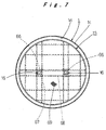
- the fixed operations platform 13 described above is disposed in the vicinity of the guide mechanism Z (see the chain line in FIG. 8) and is used by an operator to control the state of the welding, and as shown in FIG. 7, is constructed by attaching a flooring material 69 to the top of a lattice of cleats 67, 68, thereby forming a circular shaped flat structure that follows the side wall 1c of the digester 1.
- a left and right pair of post retaining members 66, 66 are provided toward the center of the fixed operations platform 13, and the posts 16, 16 are positioned so as to pass through each of these post retaining members 66, 66.
- This fixed operations platform 13 is movable in up and down direction along the posts 16, 16, and can be secured to, and supported by, the posts 16, 16 at any arbitrary height by selectively mounting securing pins (not shown in the drawing) between the post retaining members 66, 66 and the corresponding posts 16, 16. During the operation for altering the installation height of this fixed operations platform 13, the height adjustable operations platform 14 described next is used.
- each of the structural elements must be able to be disassembled down to a size capable of passing through the manhole 36 (not shown in the drawings).
- the height adjustable operations platform 14 described above is used for normal inspections, as well as for transporting materials to the fixed operations platform 13 or moving operators during the operations for conducting overlay welding on the inner wall surface 1d of the digester 1 with the aforementioned welding units 20, and as shown in FIG. 1 and FIG. 11, is formed as a circular shaped flat structure by attaching a flooring material 49 to the top of girder members 47, 48 that are assembled in a cross girder arrangement, with a predetermined spacing maintained between the periphery of the platform and the inner wall surface 1d of the digester 1.
- This height adjustable operations platform 14 is equipped with a left and right pair of post guides 62, 62 provided in the central region of the platform, and the aforementioned posts 16, 16 pass through each of these post guides 62, 62.
- Travel drive motors 30, 30 are attached to one side of each of the post guides 62, 62, namely, on the side of the posts 16 to which the racks 15 are attached, and the pinion gears (not shown in the drawings) provided on the motors 30 engage with, and travel along the racks 15 on the side of the posts 16, enabling the height adjustable operations platform 14 to move up and down along the posts 16, 16 under its own power.
- guide wheel units 25 are provided at four locations around the circumferential direction of the outer periphery of the height adjustable operations platform 14. These guide wheel units 25 run along the inner wall surface 1d of the digester 1 when the height adjustable operations platform 14 is raised or lowered, restricting sideways deviation of the height adjustable operations platform 14 and ensuring stable movement up and down.
- the guide wheel units 25 are constructed by attaching a wheel 76 to the tip of a pivoted arm 77, which is provided on the height adjustable operations platform 14 and is free to swing in the radial direction of the digester 1, and then using a damper 78 to energize the arm 77 to apply pressure continually in the outward direction.
- the wheels 76 run along the inner wall surface 1d while being pressed against the inner wall surface with a constant, predetermined pressure, stability during the raising and lowering of the height adjustable operations platform 14 is ensured at all times, and because the wheels 76 are free to deviate along the radial direction of the digester 1, the wheels 76 accommodate steps in the inner wall surface 1d, and easily ride over such steps, meaning the reliability of the movement of the height adjustable operations platform 14 is ensured.
- each of the structural elements must be able to be disassembled down to a size capable of passing through the manhole 36 (not shown in the drawings).
- the height adjustable operations platform 14 is moved up and down, while the aforementioned post pieces 16a, 16a,.. are joined together sequentially in a stacked arrangement on top of the lower fixed operations floor 6, forming the posts 16, 16, and then the upper fixed operations floor 7 that is erected at the top section 1b of the digester 1 is secured to the top ends of the posts 16, 16. This completes the installation of the posts 16, 16.
- the height adjustable operations platform 14 which moves up and down along the posts 16, 16.
- the aforementioned suspension support base 8 is assembled and secured to the digester 1, and then the suspended beam structure 9 is assembled and suspended from the suspension support base 8 via the aforementioned chain blocks 18.
- the upper guide structure 10 is suspended from the suspended beam structure 9, each of the vertical guide structures 12, 12,.. is attached to the upper guide structure 10, and the lower guide structure 11 is supported at the bottom end of each of these vertical guide structures 12, 12, .. In this state, both the upper guide structure 10 and the lower guide structure 11 are not secured to the inner wall surface 1d of the digester 1, and are movable freely in up and down direction.
- the aforementioned fixed operations platform 13 is then assembled, mounted onto the height adjustable operations platform 14, raised to a predetermined height position by raising or lowering the height adjustable operations platform 14, and then secured to the posts 16, 16.
- cables 24 extending from a welding base unit 22 disposed outside the digester 1 are passed into the digester 1 through the bottom manhole 31 of the digester 1, and are fed through to the fixed operations platform 13, and of these cables 24, the power supply cable is connected to a welding controller 23 mounted on top of the fixed operations platform 13, and the carbon dioxide gas supply hose is connected to the welding units 20, 20,.. attached to each of the vertical guide structures 12, 12,...
- each of the chain blocks 18, 18,.. are moved in synchronization with each other, and the suspended beam structure 9 is moved to a position immediately above the area targeted for welding.
- the upper guide structure 10 and the lower guide structure 11 are then secured to the inner wall surface 1d of the digester 1.
- the vertical guide structures 12, 12,.. in a state that enables relative movement with respect to the upper guide structure 10 and the lower guide structure 11 (in other words, a state in which both the check bolt 53 on the saddle 37, and the push bolt 73 on the vertical guide structure 12 are loosened)
- the position of each of the vertical guide structures 12, 12,.. relative to the inner wall surface 1d, and the mutual spacing between each vertical guide structure 12, 12,.. are adjusted.
- each of the vertical guide structures 12, 12,.. is secured to the upper guide structure 10 and the lower guide structure 11.
- the relative spacing in the left and right directions that is, the circumferential direction of the vertical guide structures 12, 12,..
- the movement direction of each of the welding units 20, 20,.. that is, the direction of weld progression
- each of the welding units 20, 20,.. is positioned at the top end of its corresponding vertical guide structure 12, 12,... Subsequently, power is supplied to each of the welding torches 85, 85 on each of the welding units 20, 20,.., and with the shield gas (carbon dioxide gas) also being supplied, each of the welding units 20, 20,.. is moved concurrently downward at a predetermined speed, and overlay welding is conducted by the welding torches 85, 85 (see the solid line sections in FIG. 13).
- the shield gas carbon dioxide gas
- each of which is equipped with two welding torches 85, and consequently pairs of parallel weld beads B 1 , B 1 that are produced with a spacing that corresponds with the spacing between the pair of welding torches 85, 85, are formed in eight locations around the inner wall surface 1d with a predetermined spacing therebetween, forming a total of 16 weld beads.
- each of the vertical guide structures 12, 12,.. and the upper guide structure 10 and the lower guide structure 11 is released, each of the vertical guide structures 12, 12,.. is moved in the left or right direction by a predetermined distance (that is, by a dimensional distance equivalent to the spacing of an aforementioned pair of welding torches 85, 85), and at this point the vertical guide structures 12, 12,.. are once again secured to the upper guide structure 10 and the lower guide structure 11.
- each torch 85 of the welding units 20, 20.. is positioned between a pair of weld beads B 1 , B 1 formed during the previous welding run.
- each of the welding units 20, 20.. is reset to a welding capable state, and each of the welding units 20, 20,.. is then moved downward at a predetermined speed, and a second overlay welding run is conducted by the welding torches 85, 85 (see the chain line sections in FIG. 13).
- the level is adjusted to the next level requiring overlay welding.
- the securing arrangement of the upper guide structure 10 and the lower guide structure 11 relative to the inner wall surface 1d of the digester 1 is released, placing the guide structures in a free state.
- each of the chain blocks 18, 18,.. is operated, and the suspended beam structure 9 is either raised or lowered by a predetermined distance (specifically, the distance in the height direction of the previous weld region) .
- the upper guide structure 10, the lower guide structure 11, and the vertical guide structures 12, 12,.. namely, the aforementioned guide mechanism Z
- the welding units 20, 20.. are positioned at the initial height for the next overlay welding operation.
- the next overlay welding operation is conducted either above or below the previous overlay welded region.
- the required thickness repair operations is performed for all the sections of reduced thickness on the inner wall surface 1d.
- the entire operation is completed by disassembling and carrying out each of the components, in the reverse order to that used during assembly.
- each of the exhaust systems 32 to 34 described above is operated continuously through the entire period from the commencement of preparatory operations through to the completion of welding operations, and this ensures good ventilation within the digester 1, and guarantees a safe operation performed in a good operating environment.
- the level adjustment accompanying the change of the welding position in the height direction is achieved solely by a suitable movement of the suspended beam structure 9 in either an up or down direction using the chain blocks 18, 18,.., and consequently compared with a conventional case in which a steel scaffold is put up inside the digester 1, and an operation for extending this scaffold must be conducted every time the welding height is altered, the operation for adjusting levels is markedly easier, the safety and operability of all operations throughout the entire welding operation, including the level adjustment operations, are improved, meaning the downtime for the digester 1 during the thickness repair operations is shortened.
- the welding units 20 are attached to the suspended beam structure 9 via the guide mechanism Z and are able to be moved up and down as well as left and right, and consequently the control of the operational status of the overlay welding conducted by the welding units 20, namely, control of factors such as the width of the weld bead, the weld direction, or the spacing between adjacent weld beads, is far simpler and more reliable than a case in which the above factors are entrusted entirely to the actions and judgment of an operator.
- overlay welding with as uniform a cladding as possible is formed over the entire region requiring overlay welding with a high level of reliability, resulting in an efficient extension of the life of the digester 1 by repairing the thickness of the wall.
- the aforementioned posts 16, 16 are put up in a vertical direction inside the digester 1, the height adjustable operations platform 14 is attached to each of these posts 16, 16 and is movable in up and down direction under its own power, and consequently by using this height adjustable operations platform 14, operating materials and operators are moved safely and rapidly to the position of the welding units 20, without requiring any scaffold height adjustments, even if the digester 1 is a blast furnace type structure of considerable height, meaning both operational speed and safety are achieved.
- the fixed operations platform 13 is attached to the posts 16 in a manner that enables the attachment height to be altered, during the welding operations an operator easily and accurately performs quality control checks of the welding produced by the welding units 20 from the fixed operations platform 13, meaning the reliability of the overlay welding is further improved.
- the digester 1 was described as one example of the "tower structure” that is the target of the present invention, but the “tower structure” is not restricted to structures such as the digester 1 with a blast furnace type construction, and for example, also includes comparatively low structures such as oil storage tanks and the like. In such cases, the posts 16 and the height adjustable operations platform 14 may not necessarily be required.
- the aforementioned “tower structure” is not restricted to pressure vessels such as the aforementioned digester 1, and also includes structures used at comparatively low pressures.
- the height position within the aforementioned tower structure of an operations unit attached to the suspended beam structure in other words, the height setting within the tower structure of the operational target region for the operations unit, is easily altered, and consequently compared with a conventional case where a scaffold is put up inside the tower structure, the height of the scaffold need not be changed every time the operating height is altered, and the operation for adjusting levels during operations is markedly easier, or even unnecessary, making the structure ideal for improving the safety and operability associated with all manner of operations.
Landscapes
- Engineering & Computer Science (AREA)
- Architecture (AREA)
- Mechanical Engineering (AREA)
- Civil Engineering (AREA)
- Structural Engineering (AREA)
- Paper (AREA)
- Movable Scaffolding (AREA)
- Butt Welding And Welding Of Specific Article (AREA)
- Conveying And Assembling Of Building Elements In Situ (AREA)
Applications Claiming Priority (3)
| Application Number | Priority Date | Filing Date | Title |
|---|---|---|---|
| JP2002136312A JP3592313B2 (ja) | 2002-05-10 | 2002-05-10 | 塔槽体の内壁面作業装置 |
| JP2002136312 | 2002-05-10 | ||
| PCT/JP2003/005793 WO2003095142A1 (fr) | 2002-05-10 | 2003-05-08 | Dispositif de travail pour surface de paroi interieure de tour reservoir et procede utilisant ce dispositif |
Publications (1)
| Publication Number | Publication Date |
|---|---|
| EP1514636A1 true EP1514636A1 (de) | 2005-03-16 |
Family
ID=29416786
Family Applications (1)
| Application Number | Title | Priority Date | Filing Date |
|---|---|---|---|
| EP03721082A Withdrawn EP1514636A1 (de) | 2002-05-10 | 2003-05-08 | Vorrichtung zur bearbeitung einer innenwandfläche eines tankturms und diese verwendendes verfahren zur bearbeitung einer innenwandfläche |
Country Status (7)
| Country | Link |
|---|---|
| US (1) | US20050150721A1 (de) |
| EP (1) | EP1514636A1 (de) |
| JP (1) | JP3592313B2 (de) |
| CN (1) | CN1638915A (de) |
| BR (1) | BR0307560A (de) |
| CA (1) | CA2473926A1 (de) |
| WO (1) | WO2003095142A1 (de) |
Cited By (3)
| Publication number | Priority date | Publication date | Assignee | Title |
|---|---|---|---|---|
| WO2015164166A1 (en) * | 2014-04-22 | 2015-10-29 | Fusion Tower Llc | A temperature-controlled liquid infusing device |
| EP2060706B1 (de) * | 2007-11-15 | 2019-07-10 | General Electric Company | Turm mit einer Plattform |
| EP3690242A1 (de) * | 2019-01-31 | 2020-08-05 | Siemens Gamesa Renewable Energy A/S | Windturbine und verfahren zur montage eines windturbinenturms |
Families Citing this family (14)
| Publication number | Priority date | Publication date | Assignee | Title |
|---|---|---|---|---|
| DK200200178A (da) | 2002-02-06 | 2003-08-07 | Vestas Wind Sys As | Ophængningsmidler til vindturbinetårne |
| CN101737273A (zh) * | 2008-11-17 | 2010-06-16 | 维斯塔斯风力系统集团公司 | 塔架、风力发电机组以及在塔架内设置平台的方法 |
| US20110005161A1 (en) * | 2009-07-09 | 2011-01-13 | Myron Noble | Leg for a self-supporting tower |
| US8919074B2 (en) * | 2009-07-13 | 2014-12-30 | Vsl International Ag | Telescopic tower assembly and method |
| ES2407756B1 (es) * | 2011-12-09 | 2014-06-10 | Esteyco Energía S.L. | Procedimiento de montaje de una torre telescópica |
| US9487960B2 (en) | 2014-06-17 | 2016-11-08 | One Energy Enterprises Llc | Suspended deck systems, kits, and methods of installing, inspecting, and repairing a suspended deck system |
| US20150376906A1 (en) * | 2014-06-30 | 2015-12-31 | Aluma Systems Inc. | Collapsible structure for vessel having interior sloping wall |
| KR102017503B1 (ko) * | 2017-06-26 | 2019-09-04 | 한국남부발전 주식회사 | 보일러용 이동식 비계장치 |
| US11571764B2 (en) | 2018-11-25 | 2023-02-07 | Turn2 Specialty Companies Llc | Weld overlay machine assembly |
| JP6994065B2 (ja) * | 2020-03-06 | 2022-01-14 | 東芝プラントシステム株式会社 | 足場、および、足場の組立方法 |
| CN112538962B (zh) * | 2020-12-28 | 2025-12-19 | 大连福佳大化石油化工股份有限公司 | 立式储罐外壁施工吊架及其安装方法 |
| CN113199116A (zh) * | 2021-04-21 | 2021-08-03 | 中国化学工程第三建设有限公司 | 一种冷箱内铝制分馏塔组对焊接方法 |
| CN115614238B (zh) * | 2021-07-16 | 2026-01-30 | 上海市机电设计研究院有限公司 | 风电机组混凝土塔筒用多功能施工平台 |
| CN120119829B (zh) * | 2025-05-13 | 2025-07-04 | 上海建工一建集团有限公司 | 一种储罐施工系统及方法 |
Family Cites Families (20)
| Publication number | Priority date | Publication date | Assignee | Title |
|---|---|---|---|---|
| US1631848A (en) * | 1925-08-01 | 1927-06-07 | Harvey J Yager | Portable scaffold |
| US2710418A (en) * | 1952-06-04 | 1955-06-14 | Ayers B Putnam | Power scaffolds |
| US3241634A (en) * | 1965-02-01 | 1966-03-22 | Clyde W Prosser | Portable scaffolds |
| US3420332A (en) * | 1967-07-14 | 1969-01-07 | Richard A Textor | Elevator for quick assemblage and use in limited access enclosures |
| US3853204A (en) * | 1972-05-15 | 1974-12-10 | Steel Corp | Apparatus for and methods of lining a furnace |
| US3866382A (en) * | 1974-02-20 | 1975-02-18 | United States Steel Corp | Apparatus for supporting workmen within an open-ended vessel and carrying materials into and out of the vessel, and method of installing such apparatus in a vessel |
| JPS5110633A (ja) * | 1974-07-17 | 1976-01-28 | Kawasaki Steel Co | Takedakachukukochikukenzobutsuno naihekisagyoyotsuriashiba |
| US4058184A (en) * | 1976-04-15 | 1977-11-15 | Hugh J. Baker & Company | Scaffold |
| JPS5355228U (de) * | 1976-10-13 | 1978-05-11 | ||
| JPS61261569A (ja) * | 1985-05-14 | 1986-11-19 | 三菱重工業株式会社 | センタポスト型ゴンドラ |
| LU86382A1 (fr) * | 1986-04-01 | 1987-12-07 | Wurth Paul Sa | Installation pour briqueter la paroi interieure d'une enceinte |
| LU87381A1 (fr) * | 1988-11-09 | 1990-06-12 | Wurth Paul Sa | Installation automatisee pour la pose d'une maconnerie sur une paroi |
| DE3839677A1 (de) * | 1988-11-24 | 1990-05-31 | Robota Gmbh | Vorrichtung zum abbrechen von schornsteinen |
| FR2660478B1 (fr) * | 1990-04-02 | 1992-07-24 | Framatome Sa | Plancher amovible pour intervention a l'interieur d'une enveloppe telle qu'un pressuriseur de reacteur nucleaire a eau sous pression. |
| JPH08145331A (ja) * | 1994-11-22 | 1996-06-07 | Mitsubishi Heavy Ind Ltd | 煙突内部作業用ゴンドラ |
| JPH08246662A (ja) * | 1995-03-14 | 1996-09-24 | Ishikawajima Harima Heavy Ind Co Ltd | ユニット足場 |
| JPH0932350A (ja) * | 1995-07-19 | 1997-02-04 | Mitsubishi Heavy Ind Ltd | 煙突等のライニング自動はつり装置 |
| NL1002196C2 (nl) * | 1996-01-29 | 1997-07-30 | Safety Floor Bvio | Verstelbare werkvloerconstructie. |
| JPH11131789A (ja) * | 1997-10-30 | 1999-05-18 | Shimizu Corp | 作業用ゴンドラ |
| US6557817B2 (en) * | 2000-01-18 | 2003-05-06 | Wilian Holding Company | Wall climbing form hoist |
-
2002
- 2002-05-10 JP JP2002136312A patent/JP3592313B2/ja not_active Expired - Fee Related
-
2003
- 2003-05-08 CA CA002473926A patent/CA2473926A1/en not_active Abandoned
- 2003-05-08 CN CNA038051168A patent/CN1638915A/zh active Pending
- 2003-05-08 US US10/502,719 patent/US20050150721A1/en not_active Abandoned
- 2003-05-08 WO PCT/JP2003/005793 patent/WO2003095142A1/ja not_active Ceased
- 2003-05-08 BR BR0307560-5A patent/BR0307560A/pt not_active Application Discontinuation
- 2003-05-08 EP EP03721082A patent/EP1514636A1/de not_active Withdrawn
Non-Patent Citations (1)
| Title |
|---|
| See references of WO03095142A1 * |
Cited By (4)
| Publication number | Priority date | Publication date | Assignee | Title |
|---|---|---|---|---|
| EP2060706B1 (de) * | 2007-11-15 | 2019-07-10 | General Electric Company | Turm mit einer Plattform |
| WO2015164166A1 (en) * | 2014-04-22 | 2015-10-29 | Fusion Tower Llc | A temperature-controlled liquid infusing device |
| EP3690242A1 (de) * | 2019-01-31 | 2020-08-05 | Siemens Gamesa Renewable Energy A/S | Windturbine und verfahren zur montage eines windturbinenturms |
| WO2020156792A1 (en) * | 2019-01-31 | 2020-08-06 | Siemens Gamesa Renewable Energy A/S | Wind turbine and method for assembling a wind turbine tower |
Also Published As
| Publication number | Publication date |
|---|---|
| US20050150721A1 (en) | 2005-07-14 |
| JP3592313B2 (ja) | 2004-11-24 |
| BR0307560A (pt) | 2005-04-26 |
| WO2003095142A1 (fr) | 2003-11-20 |
| JP2003326390A (ja) | 2003-11-18 |
| CN1638915A (zh) | 2005-07-13 |
| CA2473926A1 (en) | 2003-11-20 |
Similar Documents
| Publication | Publication Date | Title |
|---|---|---|
| US20050150721A1 (en) | Working device for inner wall surface of tower tank, and inner wall surface working method using the same | |
| JP2003326390A5 (de) | ||
| CN1023848C (zh) | 加压水核反应堆堆芯检测装置及其装卸方法和装置 | |
| EP1553244A1 (de) | Gerüstvorrichtung zur arbeit an einer innenwandfläche eines kesselturmkörpers und verfahren zur arbeit an einer innenwandfläche unter verwendung der gerüstvorrichtung | |
| CN113814676A (zh) | 一种大直径塔设备制造工法 | |
| CN112374343A (zh) | 半门式刮板取料机门架箱体梁组装及吊装方法 | |
| CN118848376A (zh) | 辅助机器人进行管道内环缝焊接的升降平台 | |
| CN110077963B (zh) | 一种大型罐体的安装方法 | |
| JPH09268778A (ja) | 有水式ガスホルダーの解体工法とその工法に使用する部材 | |
| CN116189943B (zh) | 一种闸门安装方法 | |
| JPWO2002011151A1 (ja) | 原子炉炉内構造物の保全方法 | |
| KR100951891B1 (ko) | 저장탱크용 작업대차 | |
| CN213832009U (zh) | 机舱棚预舾装单元 | |
| AU705217B2 (en) | Method and apparatus for forming cages | |
| JPH08105990A (ja) | 原子炉内構造物の据付け方法及びその方法に用いる原子炉シュラウド溶接機並びにその方法に用いる原子炉シュラウド吊具兼芯測定装置 | |
| CN116293429B (zh) | 低温乙烯大型储罐安全维修工艺 | |
| CN115743463B (zh) | 一种船舶洗涤塔安装方法 | |
| CN222154521U (zh) | 一种可升降大直径烟气管道组对焊接辅助平台 | |
| KR102903608B1 (ko) | 케이블 트레이 자동용접 시스템 | |
| CN103510712A (zh) | 多层h钢柱“┕┑”形空中对接施工工法 | |
| JP2005186158A (ja) | 容器設置現場における肉盛溶接による大型の縦形円筒形容器内面の腐食減肉溶接補修方法 | |
| CN205077876U (zh) | 一种预应力钢绞线穿束机及张拉千斤顶悬挂装置 | |
| CN218521286U (zh) | 一种烟道维护平台 | |
| KR20110035073A (ko) | 버켓 탑재장치 | |
| CN113798742B (zh) | 一种预埋支腿用自动焊接工作设备及工作方法 |
Legal Events
| Date | Code | Title | Description |
|---|---|---|---|
| PUAI | Public reference made under article 153(3) epc to a published international application that has entered the european phase |
Free format text: ORIGINAL CODE: 0009012 |
|
| 17P | Request for examination filed |
Effective date: 20041130 |
|
| AK | Designated contracting states |
Kind code of ref document: A1 Designated state(s): AT BE BG CH CY CZ DE DK EE ES FI FR GB GR HU IE IT LI LU MC NL PT RO SE SI SK TR |
|
| AX | Request for extension of the european patent |
Extension state: AL LT LV MK |
|
| DAX | Request for extension of the european patent (deleted) | ||
| RBV | Designated contracting states (corrected) |
Designated state(s): ES FI SE |
|
| REG | Reference to a national code |
Ref country code: DE Ref legal event code: 8566 |
|
| STAA | Information on the status of an ep patent application or granted ep patent |
Free format text: STATUS: THE APPLICATION IS DEEMED TO BE WITHDRAWN |
|
| 18D | Application deemed to be withdrawn |
Effective date: 20061201 |