EP1514279B1 - Dispositif optique pour applications rayons x - Google Patents
Dispositif optique pour applications rayons x Download PDFInfo
- Publication number
- EP1514279B1 EP1514279B1 EP03760747A EP03760747A EP1514279B1 EP 1514279 B1 EP1514279 B1 EP 1514279B1 EP 03760747 A EP03760747 A EP 03760747A EP 03760747 A EP03760747 A EP 03760747A EP 1514279 B1 EP1514279 B1 EP 1514279B1
- Authority
- EP
- European Patent Office
- Prior art keywords
- reflective surface
- optical
- monochromator
- rays
- incident
- Prior art date
- Legal status (The legal status is an assumption and is not a legal conclusion. Google has not performed a legal analysis and makes no representation as to the accuracy of the status listed.)
- Expired - Lifetime
Links
Images
Classifications
-
- B—PERFORMING OPERATIONS; TRANSPORTING
- B82—NANOTECHNOLOGY
- B82Y—SPECIFIC USES OR APPLICATIONS OF NANOSTRUCTURES; MEASUREMENT OR ANALYSIS OF NANOSTRUCTURES; MANUFACTURE OR TREATMENT OF NANOSTRUCTURES
- B82Y10/00—Nanotechnology for information processing, storage or transmission, e.g. quantum computing or single electron logic
-
- G—PHYSICS
- G21—NUCLEAR PHYSICS; NUCLEAR ENGINEERING
- G21K—TECHNIQUES FOR HANDLING PARTICLES OR IONISING RADIATION NOT OTHERWISE PROVIDED FOR; IRRADIATION DEVICES; GAMMA RAY OR X-RAY MICROSCOPES
- G21K1/00—Arrangements for handling particles or ionising radiation, e.g. focusing or moderating
- G21K1/06—Arrangements for handling particles or ionising radiation, e.g. focusing or moderating using diffraction, refraction or reflection, e.g. monochromators
-
- G—PHYSICS
- G21—NUCLEAR PHYSICS; NUCLEAR ENGINEERING
- G21K—TECHNIQUES FOR HANDLING PARTICLES OR IONISING RADIATION NOT OTHERWISE PROVIDED FOR; IRRADIATION DEVICES; GAMMA RAY OR X-RAY MICROSCOPES
- G21K2201/00—Arrangements for handling radiation or particles
- G21K2201/06—Arrangements for handling radiation or particles using diffractive, refractive or reflecting elements
- G21K2201/061—Arrangements for handling radiation or particles using diffractive, refractive or reflecting elements characterised by a multilayer structure
-
- G—PHYSICS
- G21—NUCLEAR PHYSICS; NUCLEAR ENGINEERING
- G21K—TECHNIQUES FOR HANDLING PARTICLES OR IONISING RADIATION NOT OTHERWISE PROVIDED FOR; IRRADIATION DEVICES; GAMMA RAY OR X-RAY MICROSCOPES
- G21K2201/00—Arrangements for handling radiation or particles
- G21K2201/06—Arrangements for handling radiation or particles using diffractive, refractive or reflecting elements
- G21K2201/062—Arrangements for handling radiation or particles using diffractive, refractive or reflecting elements the element being a crystal
-
- G—PHYSICS
- G21—NUCLEAR PHYSICS; NUCLEAR ENGINEERING
- G21K—TECHNIQUES FOR HANDLING PARTICLES OR IONISING RADIATION NOT OTHERWISE PROVIDED FOR; IRRADIATION DEVICES; GAMMA RAY OR X-RAY MICROSCOPES
- G21K2201/00—Arrangements for handling radiation or particles
- G21K2201/06—Arrangements for handling radiation or particles using diffractive, refractive or reflecting elements
- G21K2201/064—Arrangements for handling radiation or particles using diffractive, refractive or reflecting elements having a curved surface
Definitions
- the present invention relates to an optical device for X-ray instrumentation applications of high wavelength resolutions.
- the reflective surface (s) used may be in particular of multilayer type with lateral gradient.
- the invention thus applies in all areas of X-ray instrumentation using monochromators.
- the invention applies to X-ray instrumentation domains requiring excellent spectral purity and therefore the use of a monochromator.
- the basic building block of the monochromator is a crystal that achieves very high resolutions, angular and wavelength.
- the monochromator may consist of a crystal or several aligned crystals.
- n ⁇ 2d sin ⁇ ⁇
- ⁇ the wavelength of the incident radiation for which diffraction occurs
- d the spacing period between the atomic planes of the crystal involved in the diffraction
- ⁇ ⁇ the angle of incidence on those same atomic planes that is necessary for the diffraction phenomenon to occur .
- the wavelength rays ⁇ striking the crystal with a precise angle of incidence ⁇ ⁇ with respect to a certain family of atomic planes of the crystal will be diffracted by these same atomic planes if the condition of Bragg indicated above is verified.
- This phenomenon of diffraction of a monochromatic beam occurs with a certain angular acceptance ⁇ around the reference angle ⁇ ⁇ .
- the monochromators used in the devices of the type mentioned above have a very small angular acceptance.
- the angular acceptance is 0.00336 ° ( around a reference angle of incidence of approximately 20 °).
- this source may be for example of the rotating anode type, X-ray or micro-source tubes
- this source may be for example of the rotating anode type, X-ray or micro-source tubes
- Such conditioning means have the main function of orienting the largest possible part of the incident X-rays, according to an incidence (with respect to the surface of the monochromator) which is included in the range of incidence defined by the angular acceptance of the monochromator around a reference angle of incidence ⁇
- this kind of optical component can reflect X-rays only at very low angles of incidence (typically below 0.1 °).
- the flux delivered by the optics is generally small.
- the packaging means in the form of a multilayer optical element producing a one-dimensional optical effect.
- These optical elements have a parabolic shape that makes it possible to collimate the divergent incident beam, and a multilayer coating that makes it possible to diffract the incident X-rays according to the Bragg law.
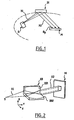
- FIG. 1 represents an X-ray source S producing an initial beam X1 having a certain divergence, destined for conditioning 31 (the parabola in which the surface of these conditioning means is shown in dotted lines).
- the conditioning means reflect the initial beam X1 in a beam X2 directed towards a monochromator M.
- Such a one-dimensional optical element is known as the Göbel mirror.
- the multilayer has a layer structure (by that is the period d of the multilayer) which varies along the mirror in order to maintain the Bragg conditions on a large surface of the mirror .
- Such a multilayer mirror with lateral gradient thus allows the reflection of X-rays whose wavelength belongs to a predetermined domain, by different regions of the mirror on which the incident rays have variable local incidence angles.
- Such conditioning means make it possible to collimate the incident beam into a beam X2 in which the directions of propagation of the X-rays are made substantially parallel to a direction incident on the monochromator which corresponds to the value ⁇ ⁇ of this monochromator, and this in the angular acceptance range of the monochromator.
- a limitation of these known one-dimensional packaging means is that for a given initial beam X1, the X-ray flux collimated in a direction compatible with the angular acceptance of the monochromator remains limited.
- the beam from the monochromator generates indeed an "image spot" whose dimensions must be of this order of magnitude.
- image plan The image spot is included in a plan called "image plan"
- the initial beam conditioning means in the form of two-dimensional optics whose reflective surface has a lateral gradient.
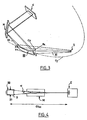
- Such optics are made in the form of a device "Kirkpatrick-Baez facing", as illustrated on the figure 2 .
- This figure thus illustrates an element 33 comprising two mirrors 331 and 332 contiguous with respect to each other (axis parallel to the direction Z for the mirror 331, the direction X for the mirror 332).
- the surfaces of these two mirrors have curvatures centered on two axes perpendicular to each other.
- each mirror 331, 332 producing a one-dimensional optical effect along an axis.
- Each of the two mirrors can thus produce a collimation, or a focus.
- a monochromator M receives the flux X2 reflected by the element 33.
- packaging means can also be made in the form of a device "KB" whose two mirrors are not arranged opposite one another.
- such two-dimensional effect conditioning means allow to recover in a range of incidences compatible with the angular acceptance of a monochromator a greater proportion of rays from a divergent initial beam X1.
- An object of the invention is to further improve the performance of these devices.
- the invention aims to collect a maximum of flux from a divergent initial beam and to output a higher monochromatic flux than can produce a device comprising conditioning means as described above.
- the invention thus aims, in particular, to increase the output flow of these devices, to allow exploiting X-ray sources of increased size.
- the invention also aims to improve the compactness of these devices.
- a device according to the invention is shown placed upstream of a sample E.
- the conditioning means are in the form of an optical element intended to reflect the rays of the initial beam X1 originating from an X-ray source S.
- the optical element 20 provides collimation in a first dimension and focus in a second, different dimension.
- the source S may be in particular of the X-ray tube type, rotating anode or source of X-ray microfocus.
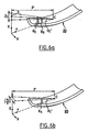
- the optical element 20 comprises a multilayer structure formed on a substrate (for example glass), which defines a reflecting surface for X-ray beam X1.
- the unique reflective surface of this optical element has a particular geometry.
- this reflective surface is shaped according to two curvatures corresponding to two different directions.
- the reflecting surface of the optical element according to the invention has a curvature Cx in the sagittal X direction, and a curvature Cy in the southern Y direction.
- Each of the curves Cx, Cy can be a circle, but also an ellipse, a parabola, or another curve (open or closed).
- the reflecting surface of the optical conditioning element does not have a simple spherical shape.
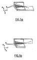
- the figure 3 represents an embodiment of the invention.
- the curve Cx produces a one-dimensional focusing
- the curve Cy produces a one-dimensional collimation
- the reflective surface of the multilayer of the optical element 20 of the figure 3 is for this purpose shaped in the respective directions X and Y according to two circular and parabolic curves Cx and Cy respectively, each of these curves producing a one-dimensional effect in a given plane, respectively in the XY plane and in the YZ plane.
- the means for conditioning the incident beam on the monochromator may be an optical element providing collimation in two dimensions.
- the monochromator M is positioned in such a way that the mean direction of the beam X2 corresponds to the angle of incidence ⁇ ⁇ of the monochromator, or to an angle compatible with the angular acceptance of this monochromator.
- conditioning means with optical elements composed of a multilayer mirror (with a lateral gradient, and possibly also with a gradient in depth, as will be seen later in this document. text), whose reflective surface can have one of several complex shapes aspherical to fulfill the function necessary to redirect the reflected beam X2 to the monochromator.
- the lateral gradient may in particular extend along the southern direction of the incident X-rays.
- the period of the multilayer may be adapted to reflect in particular the rays of Cu-K ⁇ or Mo-K ⁇ lines.
- the radius of curvature Rx may have a value of less than 20 mm, necessary for focusing over short distances, less than 90 cm (source-focusing point distance) according to a preferred application of the invention .
- the reflecting surface of the optical element 20 is defined by a multilayer.
- This multilayer (like all multilayers that will be discussed in this text) includes in almost all cases at least a "lateral gradient”.
- This characteristic makes it possible to effectively reflect X-rays having different local incidences with respect to the reflecting surface of the element 20.
- Lateral gradient multilayer means here a multilayer whose layer structure is adapted so that the Bragg condition is respected at all points of the useful surface of the mirror.
- the multilayer mirror with lateral gradient makes it possible to maintain the Bragg conditions over the entire useful surface of the mirror.
- the gradient is obtained by varying the period of the multilayer according to the position on the mirror.
- This type of multilayer structure with lateral gradient thus makes it possible to increase the solid angle of collection of the optical assembly, which leads to a higher reflected flux with respect to monolayer mirrors operating in total reflection, for a geometry of identical optics.
- the multilayer may not have a lateral gradient especially if the curvature of the optical element is low and does not require this type of gradients.
- the multilayer of the various embodiments of the invention may also have a gradient in depth.
- Such a depth gradient makes it possible to fulfill the Bragg conditions for fixed angles of incidence and variable wavelengths, or vice versa.
- the wavelength tolerance of the optical assembly (tolerant in ⁇ ) is used.
- a tolerance on the wavelength corresponding indeed - in the context of the Bragg condition - to a tolerance on the angle of incidence it is possible at constant wavelength of the incident beam to collect and to reflect a incident light flux whose rays of the same wavelength have different local incidences.
- the use of two-dimensional optics for conditioning the incident radiation on a monochromator can in particular make it possible to carry out a collimation in a first dimension in order to maintain a fixed angle of incidence on the reference plane of the monochromator, while realizing a second one-dimensional effect in a second dimension (defined by the sagittal XY plane) in order to collect a maximum of incident flux.
- the conditioning in the second dimension may be a focus or a collimation.
- such a function is represented on the figure 3 : divergent rays in the YZ plane are collimated in the YZ plane to maintain for the X2 beam (which is reflected by the conditioning element 20) an angle of incidence of the order of ⁇ ⁇ in the angular acceptance of the monochromator.
- the collimation function according to the first dimension, provided by the optical element 20, makes it possible to limit the angular divergence of the beams in the diffraction plane (for each reflected X-ray, the diffraction plane is defined as the plane perpendicular to the surface reflective material containing incident beams and reflected beams).
- conditioning in the second dimension is performed while ensuring the operating conditions of the monochromator (limit the angular divergence in the diffraction plane).
- conditioning in the second dimension can be focus or collimation.
- a divergence ⁇ on the second dimension has little influence on the incidence angle of incident X-rays on the monochromator in the case of the field of application of the invention (for the focusing conditions encountered and the types of monochromators considered).
- the divergence ⁇ in the sagittal plane is given by the useful width of the conditioning optics X I in this same plane (determined for example in the center of the optics), and the focusing distances of Foc (optical distance-spot picture).
- Limit divergences (angular tolerance on the divergence of the beam X2) of the order of 1 ° are thus calculated, which is well above the convergences required for the field of application of the invention.
- the monochromator can accept more divergence of the incident X2 beam in the second direction considered (the X direction on the figure 3 ).
- This general objective concerns both the device according to the invention and the devices using in known manner as conditioning means a KB type optical assembly.
- the invention makes it possible to collect more fluxes from the source with respect to a device implementing an initial beam conditioning by a two-dimensional optical assembly of "KB" type (facing or not) with multilayer coatings .
- the length of the component (along the southern direction) thus influences both the transverse components and the longitudinal components of the solid collection angle for the KB type optical assembly.
- the sources used are X-ray micro-sources having sizes of a few tens of microns to a few tens of microns (for example 40 microns per 40 microns) and the sample spot analyzed is of the order of one hundred microns per hundred microns (for example 300 microns per 300 microns).
- the optical combination implemented in the invention is particularly advantageous and maximizes the flux reflected by the monochromator while minimizing the size of the device.
- an elongation of the conditioning mirror in a southern direction (which is the mean direction of X-ray propagation on the optics) has the effect of increasing the multilayer surface on which a lateral gradient is applied.
- This type of gradient is applied to compensate for the curvature of the surface of the optical component.
- the gradient of the multilayers is applied along the Y axis for the two mirrors of the optical assembly.
- the increase in the solid angle of The sagittal directional collection can be done by way of example simply by increasing the size of removable slots that can be positioned at the entrance and exit of the optics.
- Another advantage of the invention is the possibility of capturing a larger source area at a given point of the optical conditioning assembly, and thus being able to maximize the flux at the image spot.
- FIGS. 6a and 6b illustrate an optical conditioning element 20 as implemented in the invention.
- the angular divergence of the incident X-rays tolerated in a sagittal direction at any point of the optics is relatively high compared to the angular divergence tolerated for the optics of the lens.
- the angular divergences tolerated at any point of the two types of two-dimensional effect optics are very close and limited by the angular acceptance of the multilayer.
- an emission beam aperture in the X direction (which corresponds to the sagittal direction) with respect to a direct beam from the center of the source causes only very small variations in the angle of incidence at any point in the optic.
- X 1 2 ⁇ p sin ⁇ s / tan ⁇ r 2 - p cos ⁇ s 2 1 ⁇ 2 .
- the values X 1 and Z 1 given above are source sizes determined within the limit of the angular acceptance of the multilayer.
- the angular acceptance of the multilayer (of the optical conditioning element 20) is 0.052 ° around an angle of 1.26 °.
- the optics and the source are aligned such that the angle of incidence ⁇ s on the optics of a beam from the center of the source is given by the Bragg angle of the multilayer.
- the source size that can be collected in a sagittal direction at the center of the optics as considered in the invention could thus be of the order of 5 cm, and about 110 microns for the Z direction.
- the source size that can be efficiently collected at a given point is limited to about 110 microns for both directions. concerned (X and Z with reference to figure 2 ). We will return to the reasons for this in the following description.
- the potential flux gain captured from the source for optical conditioning elements as considered in the invention is significant.
- the source microns 300 microns in the sagittal direction at any point of the optics and this may represent a definite advantage in the case where the desired image task is relatively wide following the sagittal direction for example for image spots 1 mm wide positioned at 40 cm from the optics.
- the device according to the invention tolerates a relatively large divergence of the beam X1 from the source, following a particular direction. This is not the case for known devices using KB type conditioning elements.
- the direction which provides a certain degree of freedom over the divergence of the incident beam effectively reflected at a given point of the optics for the first horizontal mirror 332 is the direction perpendicular to the center of the second optic which is the mirror vertical 331.
- the direction perpendicular or approximately perpendicular to the surface of a mirror corresponds to the direction in which the divergence of an incident beam causes significant variations in the angle of incidence.
- the size of the source that can be collected at a given point of the KB type sets is therefore, given the phenomenon of double reflection, limited by angular acceptance of the multilayer for the two dimensions of the source.
- the invention also makes it possible to overcome this limitation.
Landscapes
- Engineering & Computer Science (AREA)
- Physics & Mathematics (AREA)
- Chemical & Material Sciences (AREA)
- Nanotechnology (AREA)
- General Engineering & Computer Science (AREA)
- Crystallography & Structural Chemistry (AREA)
- Theoretical Computer Science (AREA)
- Spectroscopy & Molecular Physics (AREA)
- Mathematical Physics (AREA)
- High Energy & Nuclear Physics (AREA)
- Analysing Materials By The Use Of Radiation (AREA)
- Lenses (AREA)
- Optical Elements Other Than Lenses (AREA)
- Glass Compositions (AREA)
- Prostheses (AREA)
- Investigating Or Analyzing Materials By The Use Of Ultrasonic Waves (AREA)
- Optical Couplings Of Light Guides (AREA)
- Light Guides In General And Applications Therefor (AREA)
Applications Claiming Priority (5)
| Application Number | Priority Date | Filing Date | Title |
|---|---|---|---|
| FR0207546A FR2841371B1 (fr) | 2002-06-19 | 2002-06-19 | Ensemble optique et procede associe |
| FR0207546 | 2002-06-19 | ||
| FR0300623A FR2850171B1 (fr) | 2003-01-21 | 2003-01-21 | Dispositif optique pour applications rayons x |
| FR0300623 | 2003-01-21 | ||
| PCT/FR2003/001879 WO2004001769A1 (fr) | 2002-06-19 | 2003-06-19 | Dispositif optique pour applications rayons x |
Publications (2)
| Publication Number | Publication Date |
|---|---|
| EP1514279A1 EP1514279A1 (fr) | 2005-03-16 |
| EP1514279B1 true EP1514279B1 (fr) | 2009-01-14 |
Family
ID=30001927
Family Applications (3)
| Application Number | Title | Priority Date | Filing Date |
|---|---|---|---|
| EP03760747A Expired - Lifetime EP1514279B1 (fr) | 2002-06-19 | 2003-06-19 | Dispositif optique pour applications rayons x |
| EP03760756A Expired - Lifetime EP1468428B1 (fr) | 2002-06-19 | 2003-06-19 | Ensemble optique et procede associe |
| EP06120020A Ceased EP1732087A3 (fr) | 2002-06-19 | 2003-06-19 | Ensemble optique et dispositif associé |
Family Applications After (2)
| Application Number | Title | Priority Date | Filing Date |
|---|---|---|---|
| EP03760756A Expired - Lifetime EP1468428B1 (fr) | 2002-06-19 | 2003-06-19 | Ensemble optique et procede associe |
| EP06120020A Ceased EP1732087A3 (fr) | 2002-06-19 | 2003-06-19 | Ensemble optique et dispositif associé |
Country Status (8)
| Country | Link |
|---|---|
| US (2) | US7430277B2 (enExample) |
| EP (3) | EP1514279B1 (enExample) |
| JP (2) | JP2005530170A (enExample) |
| CN (2) | CN1324613C (enExample) |
| AT (2) | ATE421152T1 (enExample) |
| AU (2) | AU2003264670A1 (enExample) |
| DE (3) | DE60308645T2 (enExample) |
| WO (2) | WO2004001770A1 (enExample) |
Families Citing this family (37)
| Publication number | Priority date | Publication date | Assignee | Title |
|---|---|---|---|---|
| US20030199425A1 (en) * | 1997-06-27 | 2003-10-23 | Desai Neil P. | Compositions and methods for treatment of hyperplasia |
| DE10254026C5 (de) * | 2002-11-20 | 2009-01-29 | Incoatec Gmbh | Reflektor für Röntgenstrahlung |
| US20060040091A1 (en) | 2004-08-23 | 2006-02-23 | Bletsos Ioannis V | Breathable low-emissivity metalized sheets |
| DE102005057700A1 (de) * | 2005-11-25 | 2007-06-06 | Axo Dresden Gmbh | Röntgen-Optisches-Element |
| JP4278108B2 (ja) * | 2006-07-07 | 2009-06-10 | 株式会社リガク | 超小角x線散乱測定装置 |
| FR2918501B1 (fr) | 2007-07-02 | 2009-11-06 | Xenocs Soc Par Actions Simplif | Dispositif de delivrance d'un faisceau de rayons x a haute energie |
| US7706503B2 (en) * | 2007-11-20 | 2010-04-27 | Rigaku Innovative Technologies, Inc. | X-ray optic with varying focal points |
| EP2075569B1 (en) * | 2007-12-31 | 2012-02-15 | Xenocs S.A. | X-ray beam device |
| JP2010014418A (ja) * | 2008-07-01 | 2010-01-21 | Japan Atomic Energy Agency | 多層膜回折格子分光装置 |
| US7741626B2 (en) * | 2008-09-12 | 2010-06-22 | Cymer, Inc. | Spectral purity filters and methods therefor |
| US8050380B2 (en) * | 2009-05-05 | 2011-11-01 | Media Lario, S.R.L. | Zone-optimized mirrors and optical systems using same |
| US8249220B2 (en) * | 2009-10-14 | 2012-08-21 | Rigaku Innovative Technologies, Inc. | Multiconfiguration X-ray optical system |
| US8208602B2 (en) * | 2010-02-22 | 2012-06-26 | General Electric Company | High flux photon beams using optic devices |
| US8311184B2 (en) | 2010-08-30 | 2012-11-13 | General Electric Company | Fan-shaped X-ray beam imaging systems employing graded multilayer optic devices |
| US8488740B2 (en) * | 2010-11-18 | 2013-07-16 | Panalytical B.V. | Diffractometer |
| FR2967887B1 (fr) | 2010-11-26 | 2018-01-19 | General Electric Company | Mammographe compact, et procede de mammographie associe |
| US8744048B2 (en) | 2010-12-28 | 2014-06-03 | General Electric Company | Integrated X-ray source having a multilayer total internal reflection optic device |
| KR101332502B1 (ko) * | 2011-06-14 | 2013-11-26 | 전남대학교산학협력단 | 국부적 방사선 치료용 x―선 바늘 모듈 |
| US8761346B2 (en) | 2011-07-29 | 2014-06-24 | General Electric Company | Multilayer total internal reflection optic devices and methods of making and using the same |
| CN102903413B (zh) * | 2012-10-30 | 2015-06-03 | 同济大学 | 一种在小尺寸背光下工作的四通道kb显微成像系统 |
| US20140161233A1 (en) | 2012-12-06 | 2014-06-12 | Bruker Axs Gmbh | X-ray apparatus with deflectable electron beam |
| EP2762862B1 (en) * | 2013-01-30 | 2017-03-08 | Bruker AXS GmbH | XRF measurement apparatus for detecting contaminations on the bevel of a wafer |
| EP3066727A4 (en) * | 2013-11-07 | 2017-05-17 | MACOM Technology Solutions Holdings, Inc. | Lasers with beam shape and beam direction modification |
| EP2896960B1 (en) * | 2014-01-15 | 2017-07-26 | PANalytical B.V. | X-ray apparatus for SAXS and Bragg-Brentano measurements |
| JP6202684B2 (ja) * | 2014-06-05 | 2017-09-27 | 株式会社リガク | X線回折装置 |
| JP6069609B2 (ja) * | 2015-03-26 | 2017-02-01 | 株式会社リガク | 二重湾曲x線集光素子およびその構成体、二重湾曲x線分光素子およびその構成体の製造方法 |
| CN105092618A (zh) * | 2015-09-18 | 2015-11-25 | 北京师范大学 | 一种微束能量色散的x射线衍射仪及其使用方法 |
| CN105873344A (zh) * | 2016-03-22 | 2016-08-17 | 中国工程物理研究院流体物理研究所 | 一种基于横向梯度多层膜反射元件的x射线单能成像方法 |
| US10677744B1 (en) * | 2016-06-03 | 2020-06-09 | U.S. Department Of Energy | Multi-cone x-ray imaging Bragg crystal spectrometer |
| FR3059434B1 (fr) * | 2016-11-29 | 2019-05-17 | Centre National De La Recherche Scientifique - Cnrs | Composant de selection spectrale pour radiations xuv |
| CN106706157B (zh) * | 2017-01-11 | 2023-06-13 | 中国工程物理研究院激光聚变研究中心 | 一种基于准同视轴的icf热斑电子温度探测设备 |
| WO2020260336A1 (de) * | 2019-06-24 | 2020-12-30 | Sms Group Gmbh | Regelung der prozessparameter mittels röntgenografischer online-bestimmung von werkstoffeigenschaften bei der erzeugung metallischer bänder und bleche |
| JP7637879B2 (ja) * | 2021-01-12 | 2025-03-03 | 国立大学法人 東京大学 | ミラーの設計方法、および該設計方法における設計式が成り立つ反射面を備えた非点収差制御ミラー |
| JP7637878B2 (ja) * | 2021-01-12 | 2025-03-03 | 国立大学法人 東京大学 | ミラーの設計方法、および該設計方法における設計式が成り立つ反射面を備えた非点収差制御ミラー |
| JP7564522B2 (ja) | 2021-01-12 | 2024-10-09 | 国立大学法人 東京大学 | ミラーの設計方法、および該設計方法における設計式が成り立つ反射面を備えた非点収差制御ミラー |
| CN115389537A (zh) * | 2022-08-26 | 2022-11-25 | 同济大学 | 一种具有高通量的小焦斑中子聚焦系统 |
| CN119688594B (zh) * | 2025-02-24 | 2025-06-20 | 泸州市镀膜科技有限公司 | 一种用于电容器金属化薄膜加工的缺陷检测系统 |
Family Cites Families (18)
| Publication number | Priority date | Publication date | Assignee | Title |
|---|---|---|---|---|
| NL8300421A (nl) | 1983-02-04 | 1984-09-03 | Philips Nv | Roentgen onderzoek apparaat met dubbel focusserend kristal. |
| US4599741A (en) * | 1983-11-04 | 1986-07-08 | USC--Dept. of Materials Science | System for local X-ray excitation by monochromatic X-rays |
| US4562583A (en) * | 1984-01-17 | 1985-12-31 | The United States Of America As Represented By The Administrator Of The National Aeronautics And Space Administration | Spectral slicing X-ray telescope with variable magnification |
| DE68922306T2 (de) | 1988-03-11 | 1995-11-02 | British Tech Group | Optische vorrichtungen und methoden für ihre herstellung. |
| US5127028A (en) | 1990-08-01 | 1992-06-30 | Wittry David B | Diffractord with doubly curved surface steps |
| US5142561A (en) * | 1991-05-28 | 1992-08-25 | Grumman Aerospace Corporation | X-ray lithography scanning mirror |
| US5373544A (en) * | 1992-08-12 | 1994-12-13 | Siemens Aktiengesellschaft | X-ray diffractometer |
| US5646976A (en) * | 1994-08-01 | 1997-07-08 | Osmic, Inc. | Optical element of multilayered thin film for X-rays and neutrons |
| US5619548A (en) * | 1995-08-11 | 1997-04-08 | Oryx Instruments And Materials Corp. | X-ray thickness gauge |
| DE19615366B4 (de) * | 1996-04-19 | 2006-02-09 | Carl Zeiss Jena Gmbh | Verfahren und Einrichtung zum Nachweis physikalischer, chemischer, biologischer oder biochemischer Reaktionen und Wechselwirkungen |
| US6041099A (en) * | 1998-02-19 | 2000-03-21 | Osmic, Inc. | Single corner kirkpatrick-baez beam conditioning optic assembly |
| DE19833524B4 (de) | 1998-07-25 | 2004-09-23 | Bruker Axs Gmbh | Röntgen-Analysegerät mit Gradienten-Vielfachschicht-Spiegel |
| US6285506B1 (en) * | 1999-01-21 | 2001-09-04 | X-Ray Optical Systems, Inc. | Curved optical device and method of fabrication |
| US6278764B1 (en) * | 1999-07-22 | 2001-08-21 | The Regents Of The Unviersity Of California | High efficiency replicated x-ray optics and fabrication method |
| US6317483B1 (en) * | 1999-11-29 | 2001-11-13 | X-Ray Optical Systems, Inc. | Doubly curved optical device with graded atomic planes |
| US6829327B1 (en) * | 2000-09-22 | 2004-12-07 | X-Ray Optical Systems, Inc. | Total-reflection x-ray fluorescence apparatus and method using a doubly-curved optic |
| CN1246858C (zh) | 2001-06-19 | 2006-03-22 | X射线光学系统公司 | X射线荧光(xrf)光谱测定系统和方法 |
| DE10254026C5 (de) * | 2002-11-20 | 2009-01-29 | Incoatec Gmbh | Reflektor für Röntgenstrahlung |
-
2003
- 2003-06-19 US US10/518,284 patent/US7430277B2/en not_active Expired - Fee Related
- 2003-06-19 EP EP03760747A patent/EP1514279B1/fr not_active Expired - Lifetime
- 2003-06-19 WO PCT/FR2003/001896 patent/WO2004001770A1/fr not_active Ceased
- 2003-06-19 DE DE60308645T patent/DE60308645T2/de not_active Expired - Lifetime
- 2003-06-19 AT AT03760747T patent/ATE421152T1/de not_active IP Right Cessation
- 2003-06-19 EP EP03760756A patent/EP1468428B1/fr not_active Expired - Lifetime
- 2003-06-19 CN CNB038195275A patent/CN1324613C/zh not_active Expired - Lifetime
- 2003-06-19 AU AU2003264670A patent/AU2003264670A1/en not_active Abandoned
- 2003-06-19 US US10/506,716 patent/US7248670B2/en not_active Expired - Lifetime
- 2003-06-19 AT AT03760756T patent/ATE341083T1/de active
- 2003-06-19 JP JP2004514960A patent/JP2005530170A/ja active Pending
- 2003-06-19 EP EP06120020A patent/EP1732087A3/fr not_active Ceased
- 2003-06-19 DE DE60325853T patent/DE60325853D1/de not_active Expired - Lifetime
- 2003-06-19 AU AU2003260613A patent/AU2003260613A1/en not_active Abandoned
- 2003-06-19 CN CNB038145081A patent/CN1332399C/zh not_active Expired - Fee Related
- 2003-06-19 DE DE20320792U patent/DE20320792U1/de not_active Expired - Lifetime
- 2003-06-19 WO PCT/FR2003/001879 patent/WO2004001769A1/fr not_active Ceased
- 2003-06-19 JP JP2004514950A patent/JP2005530168A/ja active Pending
Non-Patent Citations (1)
| Title |
|---|
| SCHUSTER M.; GÖBEL H.: "parallel beam coupling into channel cut monochromators using curev graded multilayers", J PHYS D: APPL PHYS, vol. 28, 1995, pages A270 - A275, XP000538736, DOI: doi:10.1088/0022-3727/28/4A/053 * |
Also Published As
| Publication number | Publication date |
|---|---|
| EP1732087A3 (fr) | 2007-03-28 |
| CN1324613C (zh) | 2007-07-04 |
| DE60308645D1 (de) | 2006-11-09 |
| AU2003264670A1 (en) | 2004-01-06 |
| WO2004001769A1 (fr) | 2003-12-31 |
| CN1675720A (zh) | 2005-09-28 |
| CN1662999A (zh) | 2005-08-31 |
| ATE341083T1 (de) | 2006-10-15 |
| US20050117239A1 (en) | 2005-06-02 |
| CN1332399C (zh) | 2007-08-15 |
| EP1468428B1 (fr) | 2006-09-27 |
| JP2005530170A (ja) | 2005-10-06 |
| WO2004001770A1 (fr) | 2003-12-31 |
| US7430277B2 (en) | 2008-09-30 |
| AU2003260613A1 (en) | 2004-01-06 |
| ATE421152T1 (de) | 2009-01-15 |
| DE60325853D1 (de) | 2009-03-05 |
| US20060018429A1 (en) | 2006-01-26 |
| DE20320792U1 (de) | 2005-05-04 |
| DE60308645T2 (de) | 2007-10-18 |
| EP1468428A1 (fr) | 2004-10-20 |
| EP1732087A2 (fr) | 2006-12-13 |
| EP1514279A1 (fr) | 2005-03-16 |
| US7248670B2 (en) | 2007-07-24 |
| JP2005530168A (ja) | 2005-10-06 |
| WO2004001769A8 (fr) | 2005-01-06 |
Similar Documents
| Publication | Publication Date | Title |
|---|---|---|
| EP1514279B1 (fr) | Dispositif optique pour applications rayons x | |
| JP2007011403A (ja) | 徐々に変化する原子面を有する二重に湾曲した光学素子 | |
| FR2493998A1 (fr) | Dispositif de transfert d'energie optique ne formant pas d'image | |
| EP2368098A1 (fr) | Spectrometre imageur de type dyson de qualite image amelioree et a faible distorsion | |
| EP0007268B1 (fr) | Source de rayonnement optique destinée à fournir un faisceau divergent d'ouverture angulaire uniformisée | |
| EP0353138B1 (fr) | Dispositif optique multispectral à miroirs | |
| EP0702246B1 (fr) | Dispositif embarquable de mesure de rétrodiffusion de lumière | |
| FR2883384A1 (fr) | Dispositif optique de multiplexage en longueur d'onde | |
| EP0191530B1 (fr) | Chambre de Laüe | |
| FR2850171A1 (fr) | Dispositif optique pour applications rayons x | |
| FR2504308A1 (fr) | Instrument et procede pour focaliser des rayons x, des rayons gamma et des neutrons | |
| EP1920234B1 (fr) | Système optique à réflexion multiple | |
| FR2656430A1 (fr) | Dispositif de balayage et son application aux dispositifsd'analyse. | |
| EP2473824B1 (fr) | Interféromètre à compensation de champ | |
| EP4130823A1 (fr) | Dispositif pour combiner plusieurs faisceaux lumineux | |
| FR2756449A1 (fr) | Procede de generation d'un microfaisceau de rayons x et dispositif pour celui-ci | |
| WO2019137918A1 (fr) | Dispositif optique pour rayons x | |
| EP0534535A1 (fr) | Dispositif incluant un miroir fonctionnant dans le domaine des rayons X ou des neutrons | |
| FR2811148A1 (fr) | Laser pompe et milieu laser optimise | |
| FR2585468A1 (fr) | Monochromateurs a reseaux plans depourvus d'aberrations | |
| FR2858104A1 (fr) | Ensemble optique et procede associe | |
| EP0104115A2 (fr) | Dispositif viseur à champ instantané agrandi comportant un miroir, et procédé de fabrication de ce miroir | |
| FR3137767A1 (fr) | Imageur plénoptique pour rayons X à cristaux de diffraction | |
| FR2477349A1 (fr) | Dispositif optomecanique de formation d'images video, notamment pour systeme de detection d'images infrarouge | |
| WO2010086324A1 (fr) | Spectrographe a miroir elliptique |
Legal Events
| Date | Code | Title | Description |
|---|---|---|---|
| PUAI | Public reference made under article 153(3) epc to a published international application that has entered the european phase |
Free format text: ORIGINAL CODE: 0009012 |
|
| 17P | Request for examination filed |
Effective date: 20041213 |
|
| AK | Designated contracting states |
Kind code of ref document: A1 Designated state(s): AT BE BG CH CY CZ DE DK EE ES FI FR GB GR HU IE IT LI LU MC NL PT RO SE SI SK TR |
|
| AX | Request for extension of the european patent |
Extension state: AL LT LV MK |
|
| 17Q | First examination report despatched |
Effective date: 20050425 |
|
| DAX | Request for extension of the european patent (deleted) | ||
| APBN | Date of receipt of notice of appeal recorded |
Free format text: ORIGINAL CODE: EPIDOSNNOA2E |
|
| APBR | Date of receipt of statement of grounds of appeal recorded |
Free format text: ORIGINAL CODE: EPIDOSNNOA3E |
|
| APBV | Interlocutory revision of appeal recorded |
Free format text: ORIGINAL CODE: EPIDOSNIRAPE |
|
| GRAP | Despatch of communication of intention to grant a patent |
Free format text: ORIGINAL CODE: EPIDOSNIGR1 |
|
| RIC1 | Information provided on ipc code assigned before grant |
Ipc: G21K 1/06 20060101AFI20061023BHEP Ipc: G01N 23/20 20060101ALI20061023BHEP |
|
| GRAS | Grant fee paid |
Free format text: ORIGINAL CODE: EPIDOSNIGR3 |
|
| GRAA | (expected) grant |
Free format text: ORIGINAL CODE: 0009210 |
|
| AK | Designated contracting states |
Kind code of ref document: B1 Designated state(s): AT BE BG CH CY CZ DE DK EE ES FI FR GB GR HU IE IT LI LU MC NL PT RO SE SI SK TR |
|
| REG | Reference to a national code |
Ref country code: GB Ref legal event code: FG4D Free format text: NOT ENGLISH |
|
| REG | Reference to a national code |
Ref country code: CH Ref legal event code: EP |
|
| REG | Reference to a national code |
Ref country code: IE Ref legal event code: FG4D Free format text: LANGUAGE OF EP DOCUMENT: FRENCH |
|
| REF | Corresponds to: |
Ref document number: 60325853 Country of ref document: DE Date of ref document: 20090305 Kind code of ref document: P |
|
| PG25 | Lapsed in a contracting state [announced via postgrant information from national office to epo] |
Ref country code: NL Free format text: LAPSE BECAUSE OF FAILURE TO SUBMIT A TRANSLATION OF THE DESCRIPTION OR TO PAY THE FEE WITHIN THE PRESCRIBED TIME-LIMIT Effective date: 20090114 |
|
| NLV1 | Nl: lapsed or annulled due to failure to fulfill the requirements of art. 29p and 29m of the patents act | ||
| PG25 | Lapsed in a contracting state [announced via postgrant information from national office to epo] |
Ref country code: ES Free format text: LAPSE BECAUSE OF FAILURE TO SUBMIT A TRANSLATION OF THE DESCRIPTION OR TO PAY THE FEE WITHIN THE PRESCRIBED TIME-LIMIT Effective date: 20090425 Ref country code: FI Free format text: LAPSE BECAUSE OF FAILURE TO SUBMIT A TRANSLATION OF THE DESCRIPTION OR TO PAY THE FEE WITHIN THE PRESCRIBED TIME-LIMIT Effective date: 20090114 Ref country code: SI Free format text: LAPSE BECAUSE OF FAILURE TO SUBMIT A TRANSLATION OF THE DESCRIPTION OR TO PAY THE FEE WITHIN THE PRESCRIBED TIME-LIMIT Effective date: 20090114 |
|
| REG | Reference to a national code |
Ref country code: IE Ref legal event code: FD4D |
|
| PG25 | Lapsed in a contracting state [announced via postgrant information from national office to epo] |
Ref country code: AT Free format text: LAPSE BECAUSE OF FAILURE TO SUBMIT A TRANSLATION OF THE DESCRIPTION OR TO PAY THE FEE WITHIN THE PRESCRIBED TIME-LIMIT Effective date: 20090114 Ref country code: SE Free format text: LAPSE BECAUSE OF FAILURE TO SUBMIT A TRANSLATION OF THE DESCRIPTION OR TO PAY THE FEE WITHIN THE PRESCRIBED TIME-LIMIT Effective date: 20090414 Ref country code: PT Free format text: LAPSE BECAUSE OF FAILURE TO SUBMIT A TRANSLATION OF THE DESCRIPTION OR TO PAY THE FEE WITHIN THE PRESCRIBED TIME-LIMIT Effective date: 20090615 |
|
| PG25 | Lapsed in a contracting state [announced via postgrant information from national office to epo] |
Ref country code: DK Free format text: LAPSE BECAUSE OF FAILURE TO SUBMIT A TRANSLATION OF THE DESCRIPTION OR TO PAY THE FEE WITHIN THE PRESCRIBED TIME-LIMIT Effective date: 20090114 Ref country code: CZ Free format text: LAPSE BECAUSE OF FAILURE TO SUBMIT A TRANSLATION OF THE DESCRIPTION OR TO PAY THE FEE WITHIN THE PRESCRIBED TIME-LIMIT Effective date: 20090114 Ref country code: IE Free format text: LAPSE BECAUSE OF FAILURE TO SUBMIT A TRANSLATION OF THE DESCRIPTION OR TO PAY THE FEE WITHIN THE PRESCRIBED TIME-LIMIT Effective date: 20090114 Ref country code: EE Free format text: LAPSE BECAUSE OF FAILURE TO SUBMIT A TRANSLATION OF THE DESCRIPTION OR TO PAY THE FEE WITHIN THE PRESCRIBED TIME-LIMIT Effective date: 20090114 |
|
| PLBE | No opposition filed within time limit |
Free format text: ORIGINAL CODE: 0009261 |
|
| STAA | Information on the status of an ep patent application or granted ep patent |
Free format text: STATUS: NO OPPOSITION FILED WITHIN TIME LIMIT |
|
| PG25 | Lapsed in a contracting state [announced via postgrant information from national office to epo] |
Ref country code: SK Free format text: LAPSE BECAUSE OF FAILURE TO SUBMIT A TRANSLATION OF THE DESCRIPTION OR TO PAY THE FEE WITHIN THE PRESCRIBED TIME-LIMIT Effective date: 20090114 Ref country code: RO Free format text: LAPSE BECAUSE OF FAILURE TO SUBMIT A TRANSLATION OF THE DESCRIPTION OR TO PAY THE FEE WITHIN THE PRESCRIBED TIME-LIMIT Effective date: 20090114 |
|
| 26N | No opposition filed |
Effective date: 20091015 |
|
| BERE | Be: lapsed |
Owner name: XENOCS Effective date: 20090630 |
|
| PG25 | Lapsed in a contracting state [announced via postgrant information from national office to epo] |
Ref country code: BG Free format text: LAPSE BECAUSE OF FAILURE TO SUBMIT A TRANSLATION OF THE DESCRIPTION OR TO PAY THE FEE WITHIN THE PRESCRIBED TIME-LIMIT Effective date: 20090414 Ref country code: MC Free format text: LAPSE BECAUSE OF NON-PAYMENT OF DUE FEES Effective date: 20090630 |
|
| REG | Reference to a national code |
Ref country code: CH Ref legal event code: PL |
|
| PG25 | Lapsed in a contracting state [announced via postgrant information from national office to epo] |
Ref country code: CH Free format text: LAPSE BECAUSE OF NON-PAYMENT OF DUE FEES Effective date: 20090630 Ref country code: LI Free format text: LAPSE BECAUSE OF NON-PAYMENT OF DUE FEES Effective date: 20090630 |
|
| PG25 | Lapsed in a contracting state [announced via postgrant information from national office to epo] |
Ref country code: BE Free format text: LAPSE BECAUSE OF NON-PAYMENT OF DUE FEES Effective date: 20090630 |
|
| PG25 | Lapsed in a contracting state [announced via postgrant information from national office to epo] |
Ref country code: GR Free format text: LAPSE BECAUSE OF FAILURE TO SUBMIT A TRANSLATION OF THE DESCRIPTION OR TO PAY THE FEE WITHIN THE PRESCRIBED TIME-LIMIT Effective date: 20090415 |
|
| PG25 | Lapsed in a contracting state [announced via postgrant information from national office to epo] |
Ref country code: IT Free format text: LAPSE BECAUSE OF FAILURE TO SUBMIT A TRANSLATION OF THE DESCRIPTION OR TO PAY THE FEE WITHIN THE PRESCRIBED TIME-LIMIT Effective date: 20090114 |
|
| PG25 | Lapsed in a contracting state [announced via postgrant information from national office to epo] |
Ref country code: LU Free format text: LAPSE BECAUSE OF NON-PAYMENT OF DUE FEES Effective date: 20090619 |
|
| PG25 | Lapsed in a contracting state [announced via postgrant information from national office to epo] |
Ref country code: HU Free format text: LAPSE BECAUSE OF FAILURE TO SUBMIT A TRANSLATION OF THE DESCRIPTION OR TO PAY THE FEE WITHIN THE PRESCRIBED TIME-LIMIT Effective date: 20090715 |
|
| PG25 | Lapsed in a contracting state [announced via postgrant information from national office to epo] |
Ref country code: TR Free format text: LAPSE BECAUSE OF FAILURE TO SUBMIT A TRANSLATION OF THE DESCRIPTION OR TO PAY THE FEE WITHIN THE PRESCRIBED TIME-LIMIT Effective date: 20090114 |
|
| PG25 | Lapsed in a contracting state [announced via postgrant information from national office to epo] |
Ref country code: CY Free format text: LAPSE BECAUSE OF FAILURE TO SUBMIT A TRANSLATION OF THE DESCRIPTION OR TO PAY THE FEE WITHIN THE PRESCRIBED TIME-LIMIT Effective date: 20090114 |
|
| REG | Reference to a national code |
Ref country code: FR Ref legal event code: PLFP Year of fee payment: 14 |
|
| REG | Reference to a national code |
Ref country code: FR Ref legal event code: PLFP Year of fee payment: 15 |
|
| REG | Reference to a national code |
Ref country code: FR Ref legal event code: PLFP Year of fee payment: 16 |
|
| PGFP | Annual fee paid to national office [announced via postgrant information from national office to epo] |
Ref country code: FR Payment date: 20180627 Year of fee payment: 16 |
|
| PGFP | Annual fee paid to national office [announced via postgrant information from national office to epo] |
Ref country code: DE Payment date: 20180702 Year of fee payment: 16 |
|
| PGFP | Annual fee paid to national office [announced via postgrant information from national office to epo] |
Ref country code: GB Payment date: 20180718 Year of fee payment: 16 |
|
| REG | Reference to a national code |
Ref country code: DE Ref legal event code: R119 Ref document number: 60325853 Country of ref document: DE |
|
| GBPC | Gb: european patent ceased through non-payment of renewal fee |
Effective date: 20190619 |
|
| PG25 | Lapsed in a contracting state [announced via postgrant information from national office to epo] |
Ref country code: DE Free format text: LAPSE BECAUSE OF NON-PAYMENT OF DUE FEES Effective date: 20200101 Ref country code: GB Free format text: LAPSE BECAUSE OF NON-PAYMENT OF DUE FEES Effective date: 20190619 |
|
| PG25 | Lapsed in a contracting state [announced via postgrant information from national office to epo] |
Ref country code: FR Free format text: LAPSE BECAUSE OF NON-PAYMENT OF DUE FEES Effective date: 20190630 |