EP1514279B1 - Optical device for x-ray applications - Google Patents
Optical device for x-ray applications Download PDFInfo
- Publication number
- EP1514279B1 EP1514279B1 EP03760747A EP03760747A EP1514279B1 EP 1514279 B1 EP1514279 B1 EP 1514279B1 EP 03760747 A EP03760747 A EP 03760747A EP 03760747 A EP03760747 A EP 03760747A EP 1514279 B1 EP1514279 B1 EP 1514279B1
- Authority
- EP
- European Patent Office
- Prior art keywords
- reflective surface
- optical
- monochromator
- rays
- incident
- Prior art date
- Legal status (The legal status is an assumption and is not a legal conclusion. Google has not performed a legal analysis and makes no representation as to the accuracy of the status listed.)
- Expired - Lifetime
Links
- 230000003287 optical effect Effects 0.000 title claims abstract description 98
- 230000003750 conditioning effect Effects 0.000 claims description 51
- 230000000694 effects Effects 0.000 claims description 13
- 239000013078 crystal Substances 0.000 claims description 12
- 238000000576 coating method Methods 0.000 claims description 5
- 229910052732 germanium Inorganic materials 0.000 claims description 5
- GNPVGFCGXDBREM-UHFFFAOYSA-N germanium atom Chemical group [Ge] GNPVGFCGXDBREM-UHFFFAOYSA-N 0.000 claims description 5
- 239000011248 coating agent Substances 0.000 claims description 3
- 230000001151 other effect Effects 0.000 claims description 2
- 235000010627 Phaseolus vulgaris Nutrition 0.000 claims 1
- 244000046052 Phaseolus vulgaris Species 0.000 claims 1
- 239000000758 substrate Substances 0.000 abstract description 3
- 238000004519 manufacturing process Methods 0.000 abstract description 2
- 238000002310 reflectometry Methods 0.000 abstract description 2
- 230000001154 acute effect Effects 0.000 abstract 1
- 238000000034 method Methods 0.000 abstract 1
- 230000004907 flux Effects 0.000 description 17
- 229920000297 Rayon Polymers 0.000 description 11
- 239000002964 rayon Substances 0.000 description 11
- 238000004806 packaging method and process Methods 0.000 description 10
- 230000000712 assembly Effects 0.000 description 6
- 238000000429 assembly Methods 0.000 description 6
- 239000007787 solid Substances 0.000 description 6
- RYGMFSIKBFXOCR-UHFFFAOYSA-N Copper Chemical compound [Cu] RYGMFSIKBFXOCR-UHFFFAOYSA-N 0.000 description 4
- PEDCQBHIVMGVHV-UHFFFAOYSA-N Glycerine Chemical compound OCC(O)CO PEDCQBHIVMGVHV-UHFFFAOYSA-N 0.000 description 4
- 229910052802 copper Inorganic materials 0.000 description 4
- 239000010949 copper Substances 0.000 description 4
- 238000013507 mapping Methods 0.000 description 3
- 230000005855 radiation Effects 0.000 description 3
- 238000002441 X-ray diffraction Methods 0.000 description 2
- 230000006978 adaptation Effects 0.000 description 2
- 239000011521 glass Substances 0.000 description 2
- 239000010410 layer Substances 0.000 description 2
- 238000004377 microelectronic Methods 0.000 description 2
- 238000011144 upstream manufacturing Methods 0.000 description 2
- 235000014698 Brassica juncea var multisecta Nutrition 0.000 description 1
- 241000251184 Rajiformes Species 0.000 description 1
- 241000897276 Termes Species 0.000 description 1
- 230000002457 bidirectional effect Effects 0.000 description 1
- 230000001609 comparable effect Effects 0.000 description 1
- 230000008878 coupling Effects 0.000 description 1
- 238000010168 coupling process Methods 0.000 description 1
- 238000005859 coupling reaction Methods 0.000 description 1
- 238000010586 diagram Methods 0.000 description 1
- 238000006073 displacement reaction Methods 0.000 description 1
- 239000000463 material Substances 0.000 description 1
- 239000002356 single layer Substances 0.000 description 1
- 230000003595 spectral effect Effects 0.000 description 1
- 238000004846 x-ray emission Methods 0.000 description 1
Images
Classifications
-
- B—PERFORMING OPERATIONS; TRANSPORTING
- B82—NANOTECHNOLOGY
- B82Y—SPECIFIC USES OR APPLICATIONS OF NANOSTRUCTURES; MEASUREMENT OR ANALYSIS OF NANOSTRUCTURES; MANUFACTURE OR TREATMENT OF NANOSTRUCTURES
- B82Y10/00—Nanotechnology for information processing, storage or transmission, e.g. quantum computing or single electron logic
-
- G—PHYSICS
- G21—NUCLEAR PHYSICS; NUCLEAR ENGINEERING
- G21K—TECHNIQUES FOR HANDLING PARTICLES OR IONISING RADIATION NOT OTHERWISE PROVIDED FOR; IRRADIATION DEVICES; GAMMA RAY OR X-RAY MICROSCOPES
- G21K1/00—Arrangements for handling particles or ionising radiation, e.g. focusing or moderating
- G21K1/06—Arrangements for handling particles or ionising radiation, e.g. focusing or moderating using diffraction, refraction or reflection, e.g. monochromators
-
- G—PHYSICS
- G21—NUCLEAR PHYSICS; NUCLEAR ENGINEERING
- G21K—TECHNIQUES FOR HANDLING PARTICLES OR IONISING RADIATION NOT OTHERWISE PROVIDED FOR; IRRADIATION DEVICES; GAMMA RAY OR X-RAY MICROSCOPES
- G21K2201/00—Arrangements for handling radiation or particles
- G21K2201/06—Arrangements for handling radiation or particles using diffractive, refractive or reflecting elements
- G21K2201/061—Arrangements for handling radiation or particles using diffractive, refractive or reflecting elements characterised by a multilayer structure
-
- G—PHYSICS
- G21—NUCLEAR PHYSICS; NUCLEAR ENGINEERING
- G21K—TECHNIQUES FOR HANDLING PARTICLES OR IONISING RADIATION NOT OTHERWISE PROVIDED FOR; IRRADIATION DEVICES; GAMMA RAY OR X-RAY MICROSCOPES
- G21K2201/00—Arrangements for handling radiation or particles
- G21K2201/06—Arrangements for handling radiation or particles using diffractive, refractive or reflecting elements
- G21K2201/062—Arrangements for handling radiation or particles using diffractive, refractive or reflecting elements the element being a crystal
-
- G—PHYSICS
- G21—NUCLEAR PHYSICS; NUCLEAR ENGINEERING
- G21K—TECHNIQUES FOR HANDLING PARTICLES OR IONISING RADIATION NOT OTHERWISE PROVIDED FOR; IRRADIATION DEVICES; GAMMA RAY OR X-RAY MICROSCOPES
- G21K2201/00—Arrangements for handling radiation or particles
- G21K2201/06—Arrangements for handling radiation or particles using diffractive, refractive or reflecting elements
- G21K2201/064—Arrangements for handling radiation or particles using diffractive, refractive or reflecting elements having a curved surface
Definitions
- the present invention relates to an optical device for X-ray instrumentation applications of high wavelength resolutions.
- the reflective surface (s) used may be in particular of multilayer type with lateral gradient.
- the invention thus applies in all areas of X-ray instrumentation using monochromators.
- the invention applies to X-ray instrumentation domains requiring excellent spectral purity and therefore the use of a monochromator.
- the basic building block of the monochromator is a crystal that achieves very high resolutions, angular and wavelength.
- the monochromator may consist of a crystal or several aligned crystals.
- n ⁇ 2d sin ⁇ ⁇
- ⁇ the wavelength of the incident radiation for which diffraction occurs
- d the spacing period between the atomic planes of the crystal involved in the diffraction
- ⁇ ⁇ the angle of incidence on those same atomic planes that is necessary for the diffraction phenomenon to occur .
- the wavelength rays ⁇ striking the crystal with a precise angle of incidence ⁇ ⁇ with respect to a certain family of atomic planes of the crystal will be diffracted by these same atomic planes if the condition of Bragg indicated above is verified.
- This phenomenon of diffraction of a monochromatic beam occurs with a certain angular acceptance ⁇ around the reference angle ⁇ ⁇ .
- the monochromators used in the devices of the type mentioned above have a very small angular acceptance.
- the angular acceptance is 0.00336 ° ( around a reference angle of incidence of approximately 20 °).
- this source may be for example of the rotating anode type, X-ray or micro-source tubes
- this source may be for example of the rotating anode type, X-ray or micro-source tubes
- Such conditioning means have the main function of orienting the largest possible part of the incident X-rays, according to an incidence (with respect to the surface of the monochromator) which is included in the range of incidence defined by the angular acceptance of the monochromator around a reference angle of incidence ⁇
- this kind of optical component can reflect X-rays only at very low angles of incidence (typically below 0.1 °).
- the flux delivered by the optics is generally small.
- the packaging means in the form of a multilayer optical element producing a one-dimensional optical effect.
- These optical elements have a parabolic shape that makes it possible to collimate the divergent incident beam, and a multilayer coating that makes it possible to diffract the incident X-rays according to the Bragg law.
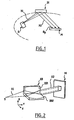
- FIG. 1 represents an X-ray source S producing an initial beam X1 having a certain divergence, destined for conditioning 31 (the parabola in which the surface of these conditioning means is shown in dotted lines).
- the conditioning means reflect the initial beam X1 in a beam X2 directed towards a monochromator M.
- Such a one-dimensional optical element is known as the Göbel mirror.
- the multilayer has a layer structure (by that is the period d of the multilayer) which varies along the mirror in order to maintain the Bragg conditions on a large surface of the mirror .
- Such a multilayer mirror with lateral gradient thus allows the reflection of X-rays whose wavelength belongs to a predetermined domain, by different regions of the mirror on which the incident rays have variable local incidence angles.
- Such conditioning means make it possible to collimate the incident beam into a beam X2 in which the directions of propagation of the X-rays are made substantially parallel to a direction incident on the monochromator which corresponds to the value ⁇ ⁇ of this monochromator, and this in the angular acceptance range of the monochromator.
- a limitation of these known one-dimensional packaging means is that for a given initial beam X1, the X-ray flux collimated in a direction compatible with the angular acceptance of the monochromator remains limited.
- the beam from the monochromator generates indeed an "image spot" whose dimensions must be of this order of magnitude.
- image plan The image spot is included in a plan called "image plan"
- the initial beam conditioning means in the form of two-dimensional optics whose reflective surface has a lateral gradient.
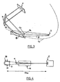
- Such optics are made in the form of a device "Kirkpatrick-Baez facing", as illustrated on the figure 2 .
- This figure thus illustrates an element 33 comprising two mirrors 331 and 332 contiguous with respect to each other (axis parallel to the direction Z for the mirror 331, the direction X for the mirror 332).
- the surfaces of these two mirrors have curvatures centered on two axes perpendicular to each other.
- each mirror 331, 332 producing a one-dimensional optical effect along an axis.
- Each of the two mirrors can thus produce a collimation, or a focus.
- a monochromator M receives the flux X2 reflected by the element 33.
- packaging means can also be made in the form of a device "KB" whose two mirrors are not arranged opposite one another.
- such two-dimensional effect conditioning means allow to recover in a range of incidences compatible with the angular acceptance of a monochromator a greater proportion of rays from a divergent initial beam X1.
- An object of the invention is to further improve the performance of these devices.
- the invention aims to collect a maximum of flux from a divergent initial beam and to output a higher monochromatic flux than can produce a device comprising conditioning means as described above.
- the invention thus aims, in particular, to increase the output flow of these devices, to allow exploiting X-ray sources of increased size.
- the invention also aims to improve the compactness of these devices.
- a device according to the invention is shown placed upstream of a sample E.
- the conditioning means are in the form of an optical element intended to reflect the rays of the initial beam X1 originating from an X-ray source S.
- the optical element 20 provides collimation in a first dimension and focus in a second, different dimension.
- the source S may be in particular of the X-ray tube type, rotating anode or source of X-ray microfocus.
- the optical element 20 comprises a multilayer structure formed on a substrate (for example glass), which defines a reflecting surface for X-ray beam X1.
- the unique reflective surface of this optical element has a particular geometry.
- this reflective surface is shaped according to two curvatures corresponding to two different directions.
- the reflecting surface of the optical element according to the invention has a curvature Cx in the sagittal X direction, and a curvature Cy in the southern Y direction.
- Each of the curves Cx, Cy can be a circle, but also an ellipse, a parabola, or another curve (open or closed).
- the reflecting surface of the optical conditioning element does not have a simple spherical shape.
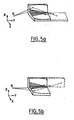
- the figure 3 represents an embodiment of the invention.
- the curve Cx produces a one-dimensional focusing
- the curve Cy produces a one-dimensional collimation
- the reflective surface of the multilayer of the optical element 20 of the figure 3 is for this purpose shaped in the respective directions X and Y according to two circular and parabolic curves Cx and Cy respectively, each of these curves producing a one-dimensional effect in a given plane, respectively in the XY plane and in the YZ plane.
- the means for conditioning the incident beam on the monochromator may be an optical element providing collimation in two dimensions.
- the monochromator M is positioned in such a way that the mean direction of the beam X2 corresponds to the angle of incidence ⁇ ⁇ of the monochromator, or to an angle compatible with the angular acceptance of this monochromator.
- conditioning means with optical elements composed of a multilayer mirror (with a lateral gradient, and possibly also with a gradient in depth, as will be seen later in this document. text), whose reflective surface can have one of several complex shapes aspherical to fulfill the function necessary to redirect the reflected beam X2 to the monochromator.
- the lateral gradient may in particular extend along the southern direction of the incident X-rays.
- the period of the multilayer may be adapted to reflect in particular the rays of Cu-K ⁇ or Mo-K ⁇ lines.
- the radius of curvature Rx may have a value of less than 20 mm, necessary for focusing over short distances, less than 90 cm (source-focusing point distance) according to a preferred application of the invention .
- the reflecting surface of the optical element 20 is defined by a multilayer.
- This multilayer (like all multilayers that will be discussed in this text) includes in almost all cases at least a "lateral gradient”.
- This characteristic makes it possible to effectively reflect X-rays having different local incidences with respect to the reflecting surface of the element 20.
- Lateral gradient multilayer means here a multilayer whose layer structure is adapted so that the Bragg condition is respected at all points of the useful surface of the mirror.
- the multilayer mirror with lateral gradient makes it possible to maintain the Bragg conditions over the entire useful surface of the mirror.
- the gradient is obtained by varying the period of the multilayer according to the position on the mirror.
- This type of multilayer structure with lateral gradient thus makes it possible to increase the solid angle of collection of the optical assembly, which leads to a higher reflected flux with respect to monolayer mirrors operating in total reflection, for a geometry of identical optics.
- the multilayer may not have a lateral gradient especially if the curvature of the optical element is low and does not require this type of gradients.
- the multilayer of the various embodiments of the invention may also have a gradient in depth.
- Such a depth gradient makes it possible to fulfill the Bragg conditions for fixed angles of incidence and variable wavelengths, or vice versa.
- the wavelength tolerance of the optical assembly (tolerant in ⁇ ) is used.
- a tolerance on the wavelength corresponding indeed - in the context of the Bragg condition - to a tolerance on the angle of incidence it is possible at constant wavelength of the incident beam to collect and to reflect a incident light flux whose rays of the same wavelength have different local incidences.
- the use of two-dimensional optics for conditioning the incident radiation on a monochromator can in particular make it possible to carry out a collimation in a first dimension in order to maintain a fixed angle of incidence on the reference plane of the monochromator, while realizing a second one-dimensional effect in a second dimension (defined by the sagittal XY plane) in order to collect a maximum of incident flux.
- the conditioning in the second dimension may be a focus or a collimation.
- such a function is represented on the figure 3 : divergent rays in the YZ plane are collimated in the YZ plane to maintain for the X2 beam (which is reflected by the conditioning element 20) an angle of incidence of the order of ⁇ ⁇ in the angular acceptance of the monochromator.
- the collimation function according to the first dimension, provided by the optical element 20, makes it possible to limit the angular divergence of the beams in the diffraction plane (for each reflected X-ray, the diffraction plane is defined as the plane perpendicular to the surface reflective material containing incident beams and reflected beams).
- conditioning in the second dimension is performed while ensuring the operating conditions of the monochromator (limit the angular divergence in the diffraction plane).
- conditioning in the second dimension can be focus or collimation.
- a divergence ⁇ on the second dimension has little influence on the incidence angle of incident X-rays on the monochromator in the case of the field of application of the invention (for the focusing conditions encountered and the types of monochromators considered).
- the divergence ⁇ in the sagittal plane is given by the useful width of the conditioning optics X I in this same plane (determined for example in the center of the optics), and the focusing distances of Foc (optical distance-spot picture).
- Limit divergences (angular tolerance on the divergence of the beam X2) of the order of 1 ° are thus calculated, which is well above the convergences required for the field of application of the invention.
- the monochromator can accept more divergence of the incident X2 beam in the second direction considered (the X direction on the figure 3 ).
- This general objective concerns both the device according to the invention and the devices using in known manner as conditioning means a KB type optical assembly.
- the invention makes it possible to collect more fluxes from the source with respect to a device implementing an initial beam conditioning by a two-dimensional optical assembly of "KB" type (facing or not) with multilayer coatings .
- the length of the component (along the southern direction) thus influences both the transverse components and the longitudinal components of the solid collection angle for the KB type optical assembly.
- the sources used are X-ray micro-sources having sizes of a few tens of microns to a few tens of microns (for example 40 microns per 40 microns) and the sample spot analyzed is of the order of one hundred microns per hundred microns (for example 300 microns per 300 microns).
- the optical combination implemented in the invention is particularly advantageous and maximizes the flux reflected by the monochromator while minimizing the size of the device.
- an elongation of the conditioning mirror in a southern direction (which is the mean direction of X-ray propagation on the optics) has the effect of increasing the multilayer surface on which a lateral gradient is applied.
- This type of gradient is applied to compensate for the curvature of the surface of the optical component.
- the gradient of the multilayers is applied along the Y axis for the two mirrors of the optical assembly.
- the increase in the solid angle of The sagittal directional collection can be done by way of example simply by increasing the size of removable slots that can be positioned at the entrance and exit of the optics.
- Another advantage of the invention is the possibility of capturing a larger source area at a given point of the optical conditioning assembly, and thus being able to maximize the flux at the image spot.
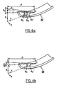
- FIGS. 6a and 6b illustrate an optical conditioning element 20 as implemented in the invention.
- the angular divergence of the incident X-rays tolerated in a sagittal direction at any point of the optics is relatively high compared to the angular divergence tolerated for the optics of the lens.
- the angular divergences tolerated at any point of the two types of two-dimensional effect optics are very close and limited by the angular acceptance of the multilayer.
- an emission beam aperture in the X direction (which corresponds to the sagittal direction) with respect to a direct beam from the center of the source causes only very small variations in the angle of incidence at any point in the optic.
- X 1 2 ⁇ p sin ⁇ s / tan ⁇ r 2 - p cos ⁇ s 2 1 ⁇ 2 .
- the values X 1 and Z 1 given above are source sizes determined within the limit of the angular acceptance of the multilayer.
- the angular acceptance of the multilayer (of the optical conditioning element 20) is 0.052 ° around an angle of 1.26 °.
- the optics and the source are aligned such that the angle of incidence ⁇ s on the optics of a beam from the center of the source is given by the Bragg angle of the multilayer.
- the source size that can be collected in a sagittal direction at the center of the optics as considered in the invention could thus be of the order of 5 cm, and about 110 microns for the Z direction.
- the source size that can be efficiently collected at a given point is limited to about 110 microns for both directions. concerned (X and Z with reference to figure 2 ). We will return to the reasons for this in the following description.
- the potential flux gain captured from the source for optical conditioning elements as considered in the invention is significant.
- the source microns 300 microns in the sagittal direction at any point of the optics and this may represent a definite advantage in the case where the desired image task is relatively wide following the sagittal direction for example for image spots 1 mm wide positioned at 40 cm from the optics.
- the device according to the invention tolerates a relatively large divergence of the beam X1 from the source, following a particular direction. This is not the case for known devices using KB type conditioning elements.
- the direction which provides a certain degree of freedom over the divergence of the incident beam effectively reflected at a given point of the optics for the first horizontal mirror 332 is the direction perpendicular to the center of the second optic which is the mirror vertical 331.
- the direction perpendicular or approximately perpendicular to the surface of a mirror corresponds to the direction in which the divergence of an incident beam causes significant variations in the angle of incidence.
- the size of the source that can be collected at a given point of the KB type sets is therefore, given the phenomenon of double reflection, limited by angular acceptance of the multilayer for the two dimensions of the source.
- the invention also makes it possible to overcome this limitation.
Abstract
Description
La présente invention concerne un dispositif optique pour des applications d'instrumentation Rayons X de hautes résolutions en longueur d'onde.The present invention relates to an optical device for X-ray instrumentation applications of high wavelength resolutions.
Plus précisément, l'invention concerne un dispositif optique destiné à traiter un faisceau incident de rayons X, ledit dispositif comprenant :
- ● un monochromateur et
- ● un élément optique de conditionnement du faisceau incident dont la surface réfléchissante est apte à produire un effet optique bidimensionnel pour adapter un faisceau à destination du monochromateur, ledit élément optique comprenant une surface réfléchissante aux rayons X de type structure multicouche.
- ● a monochromator and
- An optical element for conditioning the incident beam whose reflective surface is capable of producing a two-dimensional optical effect for adapting a beam intended for the monochromator, said optical element comprising a multilayer structure X-ray reflective surface.
On précise que la ou les surface(s) réfléchissante(s) mise(s) en oeuvre peuvent être en particulier de type multicouche à gradient latéral.It is specified that the reflective surface (s) used may be in particular of multilayer type with lateral gradient.
L'invention s'applique ainsi dans l'ensemble des domaines d'instrumentation Rayons X utilisant des monochromateurs.The invention thus applies in all areas of X-ray instrumentation using monochromators.
A titre d'exemple, on peut citer de manière non limitative les applications suivantes :
- ● Diffractométrie Rayons X de haute résolution,
- ● Fluorescente Rayons X,
- ● Applications de micro mapping (ou micro cartographie) Rayons-X pour la microélectronique.
- ● High-resolution X-ray diffractometry,
- ● Fluorescent X-Ray,
- ● Micro-mapping applications X-rays for microelectronics.
L'invention s'applique à des domaines d'instrumentation Rayons X nécessitant une excellente pureté spectrale et donc l'utilisation d'un monochromateur.The invention applies to X-ray instrumentation domains requiring excellent spectral purity and therefore the use of a monochromator.
L'élément constitutif de base du monochromateur est un cristal qui permet d'atteindre de très hautes résolutions, angulaires et en longueur d'onde. Le monochromateur peut être constitué d'un cristal ou de plusieurs cristaux alignés.The basic building block of the monochromator is a crystal that achieves very high resolutions, angular and wavelength. The monochromator may consist of a crystal or several aligned crystals.
Pour les monochromateurs du type mentionné ci-dessus, la diffraction des rayons X incidents s'effectue selon la loi de Bragg.For monochromators of the type mentioned above, incident X-ray diffraction is performed according to Bragg's law.
On rappelle que la condition de Bragg pour un cristal est de la forme nλ=2d sinθβ où n est l'ordre de réflexion, λ la longueur d'onde de la radiation incidente pour laquelle la diffraction se produit, d la période d'espacement entre les plans atomiques du cristal impliqués dans la diffraction et θβ l'angle d'incidence sur ces mêmes plans atomiques qui est nécessaire pour que le phénomène de diffraction se produise.It is recalled that the Bragg condition for a crystal is of the form nλ = 2d sinθ β where n is the order of reflection, λ the wavelength of the incident radiation for which diffraction occurs, d the spacing period between the atomic planes of the crystal involved in the diffraction and θ β the angle of incidence on those same atomic planes that is necessary for the diffraction phenomenon to occur .
Si on considère un faisceau incident de rayons X, les rayons de longueurs d'onde λ frappant le cristal avec un angle d'incidence θβ bien précis par rapport à une certaine famille de plans atomiques du cristal seront diffractés par ces mêmes plans atomiques si la condition de Bragg indiquée ci-dessus est vérifiée.If we consider an incident beam of X-rays, the wavelength rays λ striking the crystal with a precise angle of incidence θ β with respect to a certain family of atomic planes of the crystal will be diffracted by these same atomic planes if the condition of Bragg indicated above is verified.
Ce phénomène de diffraction d'un faisceau monochromatique se produit avec une certaine acceptance angulaire Δθ autour de l'angle de référence θβ.This phenomenon of diffraction of a monochromatic beam occurs with a certain angular acceptance Δθ around the reference angle θ β .
Cette acceptance angulaire peut donc être définie par :
- ● Un angle θβ correspondant à l'angle d'incidence de référence des rayons diffractés sur le monochromateur (θβ est connu sous le nom d'angle de Bragg), θβ étant fonction du cristal et de la longueur d'onde et correspondant au maximum du pic de réflectivité R=f(θ) pour une longueur d'onde donnée, et
- ● Une tolérance de Δθ autour de cet angle d'incidence de référence. La tolérance définit la largeur de l'intervalle d'incidences qui correspond à l'acceptance angulaire.
- An angle θ β corresponding to the reference angle of incidence of the diffracted rays on the monochromator (θ β is known as the Bragg angle), θ β being a function of the crystal and the wavelength and corresponding to the maximum of the reflectivity peak R = f (θ) for a given wavelength, and
- ● A tolerance of Δθ around this reference angle of incidence. The tolerance defines the width of the incidence interval that corresponds to the angular acceptance.
Les monochromateurs mis en oeuvre dans les dispositifs du type mentionné ci-dessus présentent une acceptance angulaire très réduite. A titre d'exemple, pour un monochromateur en cristal de Germanium, utilisé par exemple pour des applications où la source rayons X est une source Cuivre Ka (λ=1,54 Angströms), l'acceptance angulaire est de 0,00336° (autour d'un angle d'incidence de référence de 20° environ).The monochromators used in the devices of the type mentioned above have a very small angular acceptance. By way of example, for a Germanium crystal monochromator, used for example for applications where the X-ray source is a copper Ka source (λ = 1.54 Angstroms), the angular acceptance is 0.00336 ° ( around a reference angle of incidence of approximately 20 °).
On comprend donc qu'à partir d'une source rayons X donnée (cette source pouvant être par exemple de type anode tournante, tubes rayons X ou micro source), en l'absence d'un conditionnement approprié des rayons-X émis par la source, un grand nombre de ces rayons qui sont émis dans toutes les directions parviennent sur le monochromateur avec un angle d'incidence bien en dehors de acceptance angulaire du monochromateur.It is therefore understood that from a given X-ray source (this source may be for example of the rotating anode type, X-ray or micro-source tubes), in the absence of an appropriate packaging of the X-rays emitted by the source, a lot of these rays that are emitted in all directions reach the monochromator with an angle of incidence well outside the angular acceptance of the monochromator.
Ces photons ne pourront être réfléchis par le monochromateur et occasionnent ainsi des pertes de flux très importantes.These photons can not be reflected by the monochromator and thus cause very significant flux losses.
Pour tenter de pallier cet inconvénient, il est connu de disposer en amont du monochromateur des moyens de conditionnement du faisceau incident.In an attempt to overcome this drawback, it is known to have upstream of the monochromator means for conditioning the incident beam.
De tels moyens de conditionnement ont pour fonction principale d'orienter la plus grande partie possible des rayons X incidents, selon une incidence (par rapport à la surface du monochromateur) qui soit comprise dans la plage d'incidence définie par l'acceptance angulaire du monochromateur autour d'un angle d'incidence de référence θßSuch conditioning means have the main function of orienting the largest possible part of the incident X-rays, according to an incidence (with respect to the surface of the monochromator) which is included in the range of incidence defined by the angular acceptance of the monochromator around a reference angle of incidence θβ
Il est ainsi connu de réaliser ces moyens de conditionnement sous la forme d'un capillaire en verre permettant de collecter par réflexion totale un faisceau initial divergent issu d'une source et de le collimater en un faisceau dirigé vers un monochromateur.It is thus known to produce these conditioning means in the form of a glass capillary for collecting by total reflection a divergent initial beam from a source and to collimate it in a beam directed towards a monochromator.
Mais une limitation associée à de tels moyens de conditionnement est que ce genre de composant optique ne peut réfléchir les rayons X que sous de très faibles angles d'incidence (inférieurs à 0,1° typiquement).But a limitation associated with such conditioning means is that this kind of optical component can reflect X-rays only at very low angles of incidence (typically below 0.1 °).
En conséquence, le flux délivré par l'optique est généralement faible.As a result, the flux delivered by the optics is generally small.
Il est également connu de réaliser les moyens de conditionnement sous la forme d'un élément optique multicouche produisant un effet optique monodimensionnel. Ces éléments optiques ont une forme parabolique qui permet de collimater le faisceau incident divergent, et un revêtement multicouche qui permet de diffracter les rayons X incidents selon la loi de Bragg.It is also known to produce the packaging means in the form of a multilayer optical element producing a one-dimensional optical effect. These optical elements have a parabolic shape that makes it possible to collimate the divergent incident beam, and a multilayer coating that makes it possible to diffract the incident X-rays according to the Bragg law.
On trouvera une illustration de cette configuration connue sur la
Ici encore, les moyens de conditionnement réfléchissent le faisceau initial X1 en un faisceau X2 dirigé vers un monochromateur M.Here again, the conditioning means reflect the initial beam X1 in a beam X2 directed towards a monochromator M.
Un tel élément optique monodimensionnel est connu sous le nom de miroir de Göbel.Such a one-dimensional optical element is known as the Göbel mirror.
Dans le cas de substrats courbés tels que les miroirs de Göbel, le multicouche a une structure de couche (on entend par là la période d du multicouche) qui varie le long du miroir afin de maintenir les conditions de Bragg sur une surface importante du miroir.In the case of curved substrates such as Göbel mirrors, the multilayer has a layer structure (by that is the period d of the multilayer) which varies along the mirror in order to maintain the Bragg conditions on a large surface of the mirror .
Un tel miroir multicouche à gradient latéral permet ainsi la réflexion des rayons X dont la longueur d'onde appartient à un domaine prédéterminé, par différentes régions du miroir sur lesquelles les rayons incidents présentent des angles d'incidence locaux variables.Such a multilayer mirror with lateral gradient thus allows the reflection of X-rays whose wavelength belongs to a predetermined domain, by different regions of the mirror on which the incident rays have variable local incidence angles.
De tels moyens de conditionnement permettent de collimater le faisceau incident en un faisceau X2 dans lequel les directions de propagation des rayons X sont rendues sensiblement parallèles à une direction incidente par rapport au monochromateur qui correspond à la valeur θß de ce monochromateur, et ce dans la plage d'acceptance angulaire du monochromateur.Such conditioning means make it possible to collimate the incident beam into a beam X2 in which the directions of propagation of the X-rays are made substantially parallel to a direction incident on the monochromator which corresponds to the value θ β of this monochromator, and this in the angular acceptance range of the monochromator.
Mais de tels moyens de conditionnement ne permettent la collimation d'un faisceau initial X1 que selon un seul plan (le plan de la
Les divergences dans les plans perpendiculaires à ce plan ne sont ainsi pas traitées : il en résulte que de nombreux rayons X ne sont pas exploitables.The divergences in the planes perpendicular to this plane are thus not treated: it follows that many X-rays are not exploitable.
Une limitation de ces moyens de conditionnement connus à effet monodimensionnel est ainsi que pour un faisceau initial X1 donné, le flux de rayons X collimatés selon une direction compatible avec l'acceptance angulaire du monochromateur demeure limité.A limitation of these known one-dimensional packaging means is that for a given initial beam X1, the X-ray flux collimated in a direction compatible with the angular acceptance of the monochromator remains limited.
Et on rappelle en outre à cet égard qu'il est nécessaire d'avoir en sortie du monochromateur un faisceau de petite dimension dans les domaines d'application de l'invention (typiquement inférieur à 2mm).And it is further recalled in this regard that it is necessary to have at the output of the monochromator a small beam in the fields of application of the invention (typically less than 2mm).
Le faisceau issu du monochromateur génère en effet une « tache image » dont les dimensions doivent être de cet ordre de grandeur.The beam from the monochromator generates indeed an "image spot" whose dimensions must be of this order of magnitude.
La tache image est comprise dans un plan dit « plan image »The image spot is included in a plan called "image plan"
Pour augmenter le flux « utile » arrivant sur le monochromateur, il est connu de réaliser les moyens de conditionnement du faisceau initial sous la forme d'optiques bidimensionnels dont la surface réfléchissante présente un gradient latéral.To increase the "useful" flow arriving on the monochromator, it is known to produce the initial beam conditioning means in the form of two-dimensional optics whose reflective surface has a lateral gradient.
De tels optiques sont réalisés sous la forme d'un dispositif "Kirkpatrick-Baez en regard", comme cela est illustré sur la
Dans la suite de ce texte, on désignera par « KB » la configuration « Kirkpatrick-Baez ».In the remainder of this text, the term "KB" will be referred to as the "Kirkpatrick-Baez" configuration.
Cette figure illustre ainsi un élément 33 comportant deux miroirs 331 et 332 accolés en regard l'un de l'autre (axe parallèle à la direction Z pour le miroir 331, à la direction X pour le miroir 332).This figure thus illustrates an
Les surfaces de ces deux miroirs présentent des courbures centrées sur deux axes perpendiculaires l'un à l'autre.The surfaces of these two mirrors have curvatures centered on two axes perpendicular to each other.
Pour ce type d'optique, le conditionnement désiré est assuré par une double réflexion, chaque miroir 331, 332 produisant un effet optique monodimensionnel selon un axe.For this type of optics, the desired conditioning is provided by a double reflection, each
Chacun des deux miroirs peut ainsi produire une collimation, ou une focalisation.Each of the two mirrors can thus produce a collimation, or a focus.
Un monochromateur M reçoit le flux X2 réfléchi par l'élément 33.A monochromator M receives the flux X2 reflected by the
On trouvera une description de ce type d'élément optique 33 dans le brevet
On précise que les moyens de conditionnement peuvent également être réalisés sous la forme d'un dispositif «KB» dont les deux miroirs ne sont pas disposés en regard l'un de l'autre.It is specified that the packaging means can also be made in the form of a device "KB" whose two mirrors are not arranged opposite one another.
Par rapport à des moyens de conditionnement de type miroirs de Göbel, de tels moyens de conditionnement à effet bidimensionnel permettent de récupérer dans une plage d'incidences compatibles avec l'acceptance angulaire d'un monochromateur une plus grande proportion de rayons issus d'un faisceau initial X1 divergent.With respect to Göbel mirror-type conditioning means, such two-dimensional effect conditioning means allow to recover in a range of incidences compatible with the angular acceptance of a monochromator a greater proportion of rays from a divergent initial beam X1.
Un but de l'invention est d'améliorer encore les performances de ces dispositifs.An object of the invention is to further improve the performance of these devices.
En particulier, l'invention vise à collecter un maximum de flux à partir d'un faisceau initial divergent et produire en sortie un flux monochromatique supérieur par rapport à ce que peut produire un dispositif comprenant des moyens de conditionnement tels que décrits ci-dessus.In particular, the invention aims to collect a maximum of flux from a divergent initial beam and to output a higher monochromatic flux than can produce a device comprising conditioning means as described above.
L'invention vise ainsi notamment, pour augmenter le flux en sortie de ces dispositifs, à permettre d'exploiter des sources de rayons X de taille augmentée.The invention thus aims, in particular, to increase the output flow of these devices, to allow exploiting X-ray sources of increased size.
L'invention vise également à permettre d'améliorer la compacité de ces dispositifs.The invention also aims to improve the compactness of these devices.
Afin d'atteindre ces buts, l'invention proprose un dispositif optique destiné à traiter un faisceau incident de rayons X, ledit dispositif comprenant :
- ● un monochromateur (M) et
- ● un élément optique (20) de conditionnement du faisceau incident dont la surface réfléchissante est apte à produire un effet optique bidimensionnel pour adapter un faisceau à destination du monochromateur, ledit élément optique comprenant une surface réfléchissante aux rayons X de type structure multicouche,
- ● a monochromator (M) and
- An optical element (20) for conditioning the incident beam whose reflective surface is capable of producing a two-dimensional optical effect for adapting a beam to the monochromator, said optical element comprising a multilayer structure X-ray reflecting surface,
Des aspects préférés, mais non limitatifs, de ce dispositif sont les suivants :
- ● ladite surface réfléchissante unique est du type multicouche à gradient latéral,
- ● ladite surface réfléchissante unique comporte un gradient en profondeur,
- ● ladite surface réfléchissante a une géométrie sensiblement circulaire selon une première direction, et sensiblement parabolique selon une deuxième direction,
- ● ladite première direction est la direction sagittale de l'élément optique, et la deuxième direction est la direction méridionale de l'élément optique,
- ● ladite surface réfléchissante a une géométrie sensiblement toroïdale,
- ● ladite surface réfléchissante a une géométrie sensiblement paraboïdale,
- ● ladite surface réfléchissante a une géométrie sensiblement ellipsoïdale,
- ● ladite surface réfléchissante est apte à réfléchir des rayons des raies Cu-Kα ou Mo-Kα,
- ● le monochromateur est un cristal de germanium et l'élément optique de conditionnement est constitué d'un revêtement multicouche W/Si à gradient latéral,
- ● l'élément optique dudit dispositif a une longueur de l'ordre de 2 cm, ledit dispositif pouvant être mis en oeuvre avec une source de rayons X dont la taille est de l'ordre de quelques dizaines de microns par quelques dizaines de microns, pour produire une tache échantillon de l'ordre de 300*300 microns.
- Said single reflecting surface is of the multilayer type with lateral gradient,
- Said single reflecting surface comprises a gradient in depth,
- Said reflective surface has a substantially circular geometry in a first direction, and substantially parabolic in a second direction,
- Said first direction is the sagittal direction of the optical element, and the second direction is the southern direction of the optical element,
- Said reflective surface has a substantially toroidal geometry,
- Said reflective surface has a substantially paraboidal geometry,
- Said reflecting surface has a substantially ellipsoidal geometry,
- Said reflecting surface is capable of reflecting Cu-Kα or Mo-Kα ray rays,
- The monochromator is a germanium crystal and the optical conditioning element consists of a multilayer W / Si coating with a lateral gradient,
- The optical element of said device has a length of the order of 2 cm, said device being able to be implemented with an X-ray source whose size is of the order of a few tens of microns by a few tens of microns, to produce a sample spot of the order of 300 * 300 microns.
D'autres aspects, buts et avantages de l'invention apparaîtront mieux à la lecture de la description suivante de l'invention, faite en référence aux dessins annexés sur lesquels, outre les
- ● la
figure 3 représente une vue d'ensemble d'un dispositif optique selon un mode de mise en oeuvre de l'invention, - ● la
figure 4 est une vue de dessus du même dispositif, - ● les
figures 5a et 5b illustrent l'allongement qui serait requis dans le cas de l'adaptation de dispositifs de type connu, pour atteindre des performances comparables à un dispositif selon l'invention, qui est plus compact. - ● Les
figures 6a et 6b sont des schémas d'illustration permettant de déterminer la divergence angulaire tolérée en un point donné d'un élément optique de conditionnement à effet bidimensionnel tel que considéré dans l'invention.
- ● the
figure 3 represents an overview of an optical device according to an embodiment of the invention, - ● the
figure 4 is a top view of the same device, - ● the
Figures 5a and 5b illustrate the elongation that would be required in the case of the adaptation of devices of known type, to achieve comparable performance to a device according to the invention, which is more compact. - ● The
Figures 6a and 6b are illustrative diagrams for determining the angular divergence tolerated at a given point of a two-dimensional effect optical conditioning element as considered in the invention.
On précise en préambule à cette description que les figures sont destinées à illustrer le principe de l'invention, et ne représentent pas nécessairement les dimensions et échelles de manière réalistes.It is stated in the preamble to this description that the figures are intended to illustrate the principle of the invention, and do not necessarily represent dimensions and scales in a realistic manner.
Ceci est vrai en particulier pour les angles d'incidence (voire de réflexion) des rayons X.This is true in particular for the angles of incidence (or even reflection) of X-rays.
Ces rayons X arrivent en réalité sur les surfaces réfléchissantes selon l'invention avec une incidence inférieure à 10°.These X-rays actually arrive on the reflective surfaces according to the invention with an incidence of less than 10 °.
On définit également les directions méridionale et sagittales par rapport à la direction générale de propagation du faisceau de rayons X :
- ● La direction méridionale correspond à la direction moyenne de propagation de ce faisceau (et plus précisément à la direction moyenne entre les directions moyennes de propagation du faisceau avant et après sa réflexion sur les ensembles optiques dont il va être question),
- ● La direction sagittale correspond à une direction transversale horizontale de cette direction méridionale (la verticale étant ici définie par la normale moyenne à la partie de la surface réfléchissante des ensembles optiques qui vont être décrits et qui est effectivement utilisée pour réfléchir le faisceau de rayons X incident).
- ● The southern direction corresponds to the mean direction of propagation of this beam (and more precisely to the average direction between the mean directions of propagation of the beam before and after its reflection on the optical assemblies which will be discussed),
- ● The sagittal direction corresponds to a horizontal transverse direction of this southern direction (the vertical being here defined by the average normal to the part of the reflecting surface of the optical assemblies which will be described and which is actually used to reflect the X-ray beam incident).
En référence à la
Ce dispositif comprend :
- ● des moyens de conditionnement d'un faisceau initial de rayons X, noté X1 et présentant une certaine divergence,
- ● un monochromateur M associé à une acceptance angulaire donnée.
- ● means of conditioning an initial X-ray beam, noted X1 and having a certain divergence,
- ● a monochromator M associated with a given angular acceptance.
Les moyens de conditionnement sont dans ce mode de mise en oeuvre de l'invention réalisés sous la forme d'un élément optique 20 destiné à réfléchir les rayons du faisceau initial X1 issu d'une source S de rayons X.In this embodiment of the invention, the conditioning means are in the form of an optical element intended to reflect the rays of the initial beam X1 originating from an X-ray source S.
Dans le cas de la
La source S peut être en particulier du type tube à rayons X, anode tournant, ou encore source de rayons X à microfoyer.The source S may be in particular of the X-ray tube type, rotating anode or source of X-ray microfocus.
L'élément optique 20 comprend une structure multicouche formée sur un substrat (par exemple en verre), qui définit une surface réfléchissante pour les rayons X du faisceau X1.The
La surface réfléchissante unique de cet élément optique a une géométrie particulière.The unique reflective surface of this optical element has a particular geometry.
Plus précisément, cette surfaces réfléchissante est conformée selon deux courbures correspondant à deux directions différentes.More precisely, this reflective surface is shaped according to two curvatures corresponding to two different directions.
Et cette surface réfléchissante présente ainsi des différences importantes par rapport à des surfaces réfléchissantes du type de celles mises en oeuvre dans des ensembles optiques tels que ceux enseignés par le document
- ● La surface réfléchissante est une surface réfléchissante unique, au contraire de ce qui est le cas pour des ensembles optiques dans lesquels on a assemblé deux miroirs élémentaires différents,
- ● Cette surface réfléchissante est régulière (ce terme signifiant dans le présent texte que la surface réfléchissante ne présente pas de discontinuité de deuxième ordre : points anguleux ou arêtes - saillantes ou creuses - etc..),
- ● Par ailleurs, une différence qui est également importante est que dans le cas de l'invention, les rayons incidents ne subissent qu'une réflexion unique pour produire l'effet optique bidimensionnel désiré, alors que deux réflexions sont nécessaires dans le cas d'un ensemble optique mettant en oeuvre des moyens de conditionnement reproduisant par exemple les enseignements du document
US 6 041 099
- ● The reflective surface is a unique reflective surface, unlike for optical assemblies in which two different elementary mirrors have been assembled,
- ● This reflective surface is regular (this term means in this text that the reflecting surface does not have a discontinuity of second order: angular points or edges - protruding or hollow - etc. ..),
- ● On the other hand, a difference which is also important is that in the case of the invention, the incident rays undergo only a single reflection to produce the desired two-dimensional optical effect, whereas two reflections are necessary in the case of an optical assembly using conditioning means reproducing, for example, the teachings of the document
US 6,041,099
Avant de décrire en détail le mode de réalisation illustré sur la
La surface réfléchissante de l'élément optique selon l'invention présente une courbure Cx dans la direction X sagittale, et une courbure Cy dans la direction Y méridionale.The reflecting surface of the optical element according to the invention has a curvature Cx in the sagittal X direction, and a curvature Cy in the southern Y direction.
La
Chacune des courbes Cx, Cy peut être un cercle, mais également une ellipse, une parabole, ou une autre courbe (ouverte ou fermée).Each of the curves Cx, Cy can be a circle, but also an ellipse, a parabola, or another curve (open or closed).
En tout état de cause, la surface réfléchissante de l'élément optique de conditionnement n'a pas une forme simple sphérique.In any case, the reflecting surface of the optical conditioning element does not have a simple spherical shape.
Chacune des courbes Cx, Cy est ainsi associée à une direction différente de l'espace (deux directions perpendiculaires sur l'exemple commenté ici).Each of the curves Cx, Cy is thus associated with a different direction of space (two perpendicular directions on the example discussed here).
Et chacune de ces courbes produit sur les rayons X qui viennent être réfléchis sur la surface réfléchissante un effet optique monodimensionnel :
- ● La courbe Cx produit un effet optique monodimensionnel selon la direction X,
- ● La courbe Cy produit un effet optique monodimensionnel selon la direction Y.
- ● The Cx curve produces a one-dimensional optical effect in the X direction,
- ● The Cy curve produces a one-dimensional optical effect in the Y direction.
Et chacun de ces effets dimensionnels dépend de la courbure associée à la courbe, et de sa loi d'évolution le long de cette courbe.And each of these dimensional effects depends on the curvature associated with the curve, and its law of evolution along this curve.
On pourra ainsi paramétrer les courbes Cx et Cy pour obtenir sélectivement des effets monodimensionnels associés tels qu'une focalisation ou une collimation monodimensionnelle.It will thus be possible to parameterize the curves Cx and Cy to selectively obtain associated one-dimensional effects such as one-dimensional focusing or collimation.
La
Dans ce mode de réalisation, la courbe Cx produit une focalisation monodimensionnelle, et la courbe Cy produit une collimation monodimensionnelle.In this embodiment, the curve Cx produces a one-dimensional focusing, and the curve Cy produces a one-dimensional collimation.
La surface réfléchissante du multicouche de l'élément optique 20 de la
On génère ainsi à partir du faisceau X1 divergent une collimation dans une dimension de l'espace et une focalisation dans une autre dimension.Thus, from the diverging X1 beam, a collimation in one dimension of the space and a focus in another dimension are generated.
Selon une variante les moyens de conditionnement du faisceau incident sur le monochromateur peuvent être un élément optique assurant une collimation en deux dimensions.According to one variant, the means for conditioning the incident beam on the monochromator may be an optical element providing collimation in two dimensions.
Dans ce cas, les courbes Cx et Cy sont toutes deux conformées en paraboles.In this case, the curves Cx and Cy are both shaped into parabolas.
Revenant au mode de réalisation de l'invention de la
On maximise de la sorte dans la direction verticale (direction Z) mais également dans la direction sagittale le flux de rayons X qui arrive sur le monochromateur à l'intérieur des tolérances définies par l'acceptance angulaire de ce monochromateur.This maximizes in the vertical direction (Z direction) but also in the sagittal direction the X-ray flux that arrives on the monochromator within the tolerances defined by the angular acceptance of this monochromator.
On précise qu'il est ainsi possible de réaliser selon l'invention des moyens de conditionnement avec des éléments optiques composés d'un miroir multicouche (à gradient latéral, et éventuellement en outre à gradient en profondeur comme on va le voir plus loin dans ce texte), dont la surface réfléchissante peut avoir une parmi différentes formes complexes asphériques permettant de remplir la fonction nécessaire pour rediriger le faisceau réfléchi X2 vers le monochromateur.It is specified that it is thus possible to produce, according to the invention, conditioning means with optical elements composed of a multilayer mirror (with a lateral gradient, and possibly also with a gradient in depth, as will be seen later in this document. text), whose reflective surface can have one of several complex shapes aspherical to fulfill the function necessary to redirect the reflected beam X2 to the monochromator.
Il est ainsi possible en particulier de donner à cette surface réfléchissante une des géométries suivantes :
- ● géométrie de forme sensiblement toroïdale,
- ● géométrie de forme sensiblement paraboloïdale,
- ● géométrie de forme sensiblement ellipsoïdale,
- ● géométrie de forme sensiblement circulaire selon une première direction (en particulier la direction sagittale), et sensiblement parabolique selon une deuxième direction (en particulier la direction méridionale).
- ● geometry of substantially toroidal shape,
- ● geometry of substantially paraboloidal shape,
- Geometry of substantially ellipsoidal shape,
- ● Geometry of substantially circular shape in a first direction (in particular the sagittal direction), and substantially parabolic in a second direction (particularly the southern direction).
Le gradient latéral, pourra en particulier s'étendre selon la direction méridionale des rayons X incidents.The lateral gradient may in particular extend along the southern direction of the incident X-rays.
Et la période du multicouche pourra être adaptée pour réfléchir en particulier des rayons des raies Cu-Kα ou Mo-Kα.And the period of the multilayer may be adapted to reflect in particular the rays of Cu-Kα or Mo-Kα lines.
Dans le cas d'un mode de réalisation de l'invention avec une focalisation dans le plan sagittal, (c'est-à-dire dans le plan X Y dans la
On remarquera que l'élément optique utilisé comme moyen de conditionnement de faisceau dans le dispositif selon l'invention permet de s'affranchir des inconvénients et limitations des ensembles optiques de type KB. En particulier :
- ● cet ensemble optique est monopièce (ne nécessitant pas d'assemblage délicat).
- ● les rayons X incidents ne subissent qu'une réflexion unique sur sa surface réfléchissante.
- ● this optical assembly is one-piece (does not require delicate assembly).
- ● the incident X-rays undergo only a single reflection on its reflective surface.
On a dit que la surface réfléchissante de l'élément optique 20 était définie par un multicouche.It has been said that the reflecting surface of the
Ce multicouche (comme tous les multicouches dont il sera question dans ce texte) comporte dans pratiquement tous les cas au minimum un « gradient latéral ».This multilayer (like all multilayers that will be discussed in this text) includes in almost all cases at least a "lateral gradient".
Cette caractéristique permet de réfléchir efficacement des rayons X présentant des incidences locales différentes par rapport à la surface réfléchissante de l'élément 20.This characteristic makes it possible to effectively reflect X-rays having different local incidences with respect to the reflecting surface of the
On comprend en effet que les différents endroits de cette surface réfléchissante ne reçoivent pas les rayons X incidents avec la même incidence locale (du fait de la divergence du faisceau incident, et de la géométrie de cette surface réfléchissante).It is clear that the different places of this reflecting surface do not receive the incident X-rays with the same local incidence (because of the divergence of the incident beam, and the geometry of this reflecting surface).
Par multicouche à gradient latéral, on entend ici un multicouche dont la structure de couche est adaptée pour que la condition de Bragg soit respectée en tout point de la surface utile du miroir.Lateral gradient multilayer means here a multilayer whose layer structure is adapted so that the Bragg condition is respected at all points of the useful surface of the mirror.
Ainsi, pour un rayonnement de rayons X incidents selon une bande étroite de longueur d'onde contenant par exemple les raies Kα du cuivre (raies Cu-Kα de longueurs d'onde voisines de 0.154 nm), le miroir multicouche à gradient latéral permet de maintenir les conditions de Bragg sur l'ensemble de la surface utile du miroir.Thus, for an incident X-ray radiation in a narrow wavelength band containing, for example, Kα lines of copper (Cu-Kα lines of wavelengths close to 0.154 nm), the multilayer mirror with lateral gradient makes it possible to maintain the Bragg conditions over the entire useful surface of the mirror.
Ceci conduit à la réflexion de la bande de longueur d'onde prédéterminée (dans l'exemple ci-dessus contenant les raies Cuivre Kα), par différentes régions du miroir sur lesquelles les rayons incidents présentant des angles d'incidence locaux variables.This leads to the reflection of the predetermined wavelength band (in the above example containing Kα copper lines), by different regions of the mirror on which incident rays with varying local incidence angles.
On peut ainsi augmenter la surface du miroir qui est effectivement utilisée.It is thus possible to increase the surface area of the mirror that is actually used.
Le gradient est obtenu en faisant varier la période du multicouche en fonction de la position sur le miroir.The gradient is obtained by varying the period of the multilayer according to the position on the mirror.
Ce type de structure multicouche à gradient latéral permet ainsi d'augmenter l'angle solide de collection de l'ensemble optique, ce qui conduit à un flux réfléchi plus élevé par rapport à des miroirs monocouches fonctionnant en réflexion totale, pour une géométrie d'optique identique.This type of multilayer structure with lateral gradient thus makes it possible to increase the solid angle of collection of the optical assembly, which leads to a higher reflected flux with respect to monolayer mirrors operating in total reflection, for a geometry of identical optics.
On notera toutefois que dans des cas extrêmes, le multicouche pourra ne pas posséder de gradient latéral notamment si la courbure de l'élément optique est faible et ne nécessite pas ce type de gradients.Note however that in extreme cases, the multilayer may not have a lateral gradient especially if the curvature of the optical element is low and does not require this type of gradients.
On précise que le multicouche des différents modes de réalisation de l'invention peut également présenter un gradient en profondeur.It is specified that the multilayer of the various embodiments of the invention may also have a gradient in depth.
Un tel gradient en profondeur permet de remplir les conditions de Bragg pour des angles d'incidences fixes et des longueurs d'ondes variables, ou vice-versa.Such a depth gradient makes it possible to fulfill the Bragg conditions for fixed angles of incidence and variable wavelengths, or vice versa.
Il est ainsi possible par exemple d'augmenter la bande passante en longueur d'onde du multicouche de l'ensemble optique, et de focaliser ou collimater des rayons X de longueurs d'ondes différentes, au niveau d'un même plan image donné (cas d'une géométrie fixe - c'est à dire d'une configuration dans laquelle les positions relatives de la source de rayons incidents, de l'ensemble optique et du plan image sont fixes).It is thus possible, for example, to increase the wavelength bandwidth of the multilayer of the optical assembly, and to focus or collimate X-rays of different wavelengths, at the same given image plane ( case of a fixed geometry - that is to say of a configuration in which the relative positions of the source of incident rays, the optical assembly and the image plane are fixed).
On peut de la sorte utiliser des sources de rayons X de longueurs d'ondes différentes pour réfléchir les rayons X issus des différentes sources avec le même ensemble optique, sans que cela nécessite un nouveau positionnement de la source et/ou du ou des plan(s) image par rapport à l'ensemble optique.In this way it is possible to use X-ray sources of different wavelengths to reflect the X-rays coming from the different sources with the same optical assembly, without this necessitating a new positioning of the source and / or of the plane or planes ( s) image with respect to the optical assembly.
On utilise dans ce cas la tolérance en longueur d'onde de J'ensemble optique (tolérante en Δλ).In this case, the wavelength tolerance of the optical assembly (tolerant in Δλ) is used.
De la même façon, il est également possible de traduire cette tolérance en Δλ en une tolérance en Δθ, θ étant l'angle d'incidence sur l'élément 20.In the same way, it is also possible to translate this tolerance in Δλ into a tolerance in Δθ, θ being the angle of incidence on the
Une tolérance sur la longueur d'onde correspondant en effet - dans le cadre de la condition de Bragg - à une tolérance sur l'angle d'incidence, il est possible à longueur d'onde constante du faisceau incident de collecter et de réfléchir un flux lumineux incident dont les rayons de même longueur d'onde ont des incidences locales différentes.A tolerance on the wavelength corresponding indeed - in the context of the Bragg condition - to a tolerance on the angle of incidence, it is possible at constant wavelength of the incident beam to collect and to reflect a incident light flux whose rays of the same wavelength have different local incidences.
On peut en particulier de la sorte utiliser des sources de rayons X de plus grande dimension (augmentation de l'acceptance angulaire du composant optique).In particular, it is possible to use X-ray sources of larger size (increasing the angular acceptance of the optical component).
Le fait de réaliser les moyens de conditionnement avec un gradient en profondeur sur le multicouche constitue ainsi une option de mise en oeuvre de l'invention.The fact of making the conditioning means with a gradient in depth on the multilayer is thus an option for implementing the invention.
L'utilisation d'une optique bidimensionnelle pour le conditionnement du rayonnement incident sur un monochromateur peut en particulier permettre de réaliser une collimation dans une première dimension afin de maintenir un angle d'incidence fixe sur le plan de référence du monochromateur, tout en réalisant un deuxième effet monodimensionel dans une deuxième dimension (défnie par le plan X Y sagittal) afin de collecter un maximum de flux incident.The use of two-dimensional optics for conditioning the incident radiation on a monochromator can in particular make it possible to carry out a collimation in a first dimension in order to maintain a fixed angle of incidence on the reference plane of the monochromator, while realizing a second one-dimensional effect in a second dimension (defined by the sagittal XY plane) in order to collect a maximum of incident flux.
Le conditionnement dans la deuxième dimension peut être une focalisation ou une collimation.The conditioning in the second dimension may be a focus or a collimation.
A titre d'illustration, une telle fonction est représentée sur la
La fonction de collimation selon la première dimension, assurée par l'élément optique 20, permet de limiter la divergence angulaire des faisceaux dans le plan de diffraction (pour chaque rayon X réfléchi, le plan de diffraction est défini comme le plan perpendiculaire à la surface réfléchissante contenant les faisceaux incidents et les faisceaux réfléchis).The collimation function according to the first dimension, provided by the
Dans le but d'augmenter le flux de rayons X capté au niveau de l'échantillon, il est intéressant d'effectuer un conditionnement suivant une deuxième dimension, par exemple dans le cas de la
Ceci permet de limiter la divergence dans ce plan et de maximiser ainsi le flux de rayons X capté à partir de la source et projeté au niveau de l'échantillon après réflexion sur le monochromateur.This makes it possible to limit the divergence in this plane and thus maximize the flow of X-rays picked up from the source and projected at the level of the sample after reflection on the monochromator.
Ce conditionnement dans la deuxième dimension (toujours en référence à la
La possibilité d'augmenter le flux suivant la deuxième direction (sagittale) en effectuant une focalisation est d'autant plus intéressante que la divergence angulaire α tolérée dans le plan sagittal au niveau du monochromateur est importante dans le cas des applications considérées.The possibility of increasing the flow along the second (sagittal) direction by focusing is all the more interesting since the α-angle divergence tolerated in the sagittal plane at the level of the monochromator is important in the case of the applications considered.
En effet, une divergence α sur la deuxième dimension (dimension sagittale) influence peu l'angle d'incidence des rayons X incidents sur le monochromateur dans le cas du domaine d'application de l'invention (pour les conditions de focalisations rencontrées et les types de monochromateurs considérées).Indeed, a divergence α on the second dimension (sagittal dimension) has little influence on the incidence angle of incident X-rays on the monochromator in the case of the field of application of the invention (for the focusing conditions encountered and the types of monochromators considered).
En référence à la ![]()
![]()
Il est connu que la tolérance angulaire d'un monochromateur sur une divergence α dans le plan sagittal (que l'on nommera Δα) est fonction de l'angle de Bragg θβ et de acceptance angulaire Δθ de ce monochromateur. En référence au document de ![]()
![]()
La tolérance sur la divergence angulaire dans le plan sagittal peut ainsi être déterminée à titre d'exemple pour un cristal de germanium pour des applications Cu-Kα (θβ=22,65°, Δθ=0,00336°).The tolerance on the angular divergence in the sagittal plane can thus be determined by way of example for a germanium crystal for Cu-Kα applications (θ β = 22.65 °, Δθ = 0.00336 °).
On calcule ainsi des divergences limites (tolérance angulaire sur la divergence du faisceau X2) de l'ordre de 1°, ce qui est bien au dessus des convergences requises pour le domaine d'application de l'invention.Limit divergences (angular tolerance on the divergence of the beam X2) of the order of 1 ° are thus calculated, which is well above the convergences required for the field of application of the invention.
En conséquence, le monochromateur peut accepter plus de divergence du faisceau X2 incident suivant la deuxième direction considérée (la direction X sur la
Il est donc intéressant de collecter un maximum de flux à partir de la source pour la deuxième direction considérée (direction sagittale).It is therefore interesting to collect a maximum of flux from the source for the second direction considered (sagittal direction).
Cet objectif général concerne aussi bien le dispositif selon l'invention que les dispositifs utilisant de manière connue comme moyens de conditionnement un ensembles optique de type KB.This general objective concerns both the device according to the invention and the devices using in known manner as conditioning means a KB type optical assembly.
Suivant la deuxième directions considérée, c'est à dire la direction pour laquelle le monochromateur peut tolérer plus de divergence (dans le cas de la
Deux phénomènes sont à l'origine de ce gain de flux et nous allons les expliquer ci-dessous.
- ● Premièrement, dans le cas de l'invention avec un élément optique tel que l'élément 20, ayant une longueur donnée (selon la direction méridionale), on obtient un angle de capture dans la direction sagittale qui est plus important que ce que l'on obtient avec une configuration classique mettant en oeuvre un conditionnement par optique KB,
- ● Deuxièmement, l'élément optique bidimensionnel 20 tel que mis en oeuvre dans l'invention peut accepter plus de divergence du faisceau initial X1 dans une direction sagittale, et capte donc une surface de la source plus grande en un point quelconque de cet élément 20.
- ● First, in the case of the invention with an optical element such as the
element 20, having a given length (in the southern direction), a capture angle is obtained in the sagittal direction which is more important than what is obtained with a conventional configuration implementing an optical packaging KB, - Secondly, the two-dimensional optical element as implemented in the invention can accept more divergence of the initial beam X1 in a sagittal direction, and thus captures a larger source area at any point of this element. .
En effet, et en référence au premier type d'avantage mentionné ci-dessus, dans le cas du conditionnement réalisé par un ensemble optique de type KB, pour augmenter l'angle solide de collection suivant une direction transverse à la direction moyenne de propagation du faisceau sur J'ensemble optique, il est nécessaire d'augmenter la longueur de cet ensemble optique.Indeed, and with reference to the first type of advantage mentioned above, in the case of packaging made by a KB-type optical assembly, to increase the solid angle of collection along a direction transverse to the mean direction of propagation of the beam on optical assembly, it is necessary to increase the length of this optical assembly.
En effet, l'obtention d'un effet bidimensionnel selon une configuration KB est lié à une double réflexion.Indeed, obtaining a two-dimensional effect according to a KB configuration is linked to a double reflection.
A titre d'illustration et en considérant la
Ce phénomène est illustré sur les
Il est en effet connu que pour les éléments optiques de type KB tout rayon incident doit frapper l'optique dans une zone particulière (correspondant aux zones hachurées sur les
Il en résulte donc que pour un tel type connu d'élément optique de conditionnement (que les miroirs soient accolés ou non) l'angle solide pouvant être collecté est limité par la longueur du composant aussi bien pour les directions transverses horizontales que pour les directions transverses verticales (direction Z ou direction X).It follows therefore that for such a known type of optical conditioning element (whether the mirrors are contiguous or not) the solid angle that can be collected is limited by the length of the component both for horizontal transverse directions and directions vertical transverse (Z direction or X direction).
La longueur du composant (suivant la direction méridionale) influe donc à la fois sur les composantes transverses et les composantes longitudinales de l'angle solide de collection pour l'ensemble optique de type KB.The length of the component (along the southern direction) thus influences both the transverse components and the longitudinal components of the solid collection angle for the KB type optical assembly.
Dans le cas de l'invention, il est possible d'augmenter l'angle solide de collection suivant une direction sagittale, sans augmenter la longueur du dispositif.In the case of the invention, it is possible to increase the solid collection angle in a sagittal direction, without increasing the length of the device.
Ceci est important notamment dans le cas où l'on souhaite limiter l'encombrement et donc la taille de l'optique.This is important especially in the case where it is desired to limit the size and therefore the size of the optics.
Cela est notamment le cas à titre d'exemple pour des applications de micro-cartographie rayons X pour la microélectronique où les sources utilisées sont des micro-sources rayons X ayant des tailles de quelques dizaines de microns par quelques dizaines de microns (par exemple 40 microns par 40 microns) et la tache échantillon analysée est de l'ordre d'une centaine de microns par une centaine de microns (par exemple 300 microns par 300 microns).This is particularly the case, for example, for X-ray micro-mapping applications for microelectronics where the sources used are X-ray micro-sources having sizes of a few tens of microns to a few tens of microns (for example 40 microns per 40 microns) and the sample spot analyzed is of the order of one hundred microns per hundred microns (for example 300 microns per 300 microns).
On désire dans ce cas limiter Ja longueur de l'élément optique de conditionnement à environ 2cm.In this case it is desired to limit the length of the optical conditioning element to approximately 2 cm.
Et de manière générale, pour les applications où on cherche à limiter la longueur du dispositif, la combinaison optique mise en oeuvre dans l'invention se révèle particulièrement avantageuse et permet de maximiser le flux réfléchit par le monochromateur tout en minimisant la taille du dispositif.And in general, for applications where it is sought to limit the length of the device, the optical combination implemented in the invention is particularly advantageous and maximizes the flux reflected by the monochromator while minimizing the size of the device.
En outre, un allongement du miroir de conditionnement suivant une direction méridionale (qui est la direction moyenne de propagation des rayons X sur l'optique) a pour effet d'augmenter la surface de multicouche sur laquelle un gradient latéral est appliqué.In addition, an elongation of the conditioning mirror in a southern direction (which is the mean direction of X-ray propagation on the optics) has the effect of increasing the multilayer surface on which a lateral gradient is applied.
Ce type de gradient est appliqué pour compenser la courbure de la surface du composant optique.This type of gradient is applied to compensate for the curvature of the surface of the optical component.
Sur les
En conséquence augmenter la longueur du composant revient à augmenter la surface sur laquelle un gradient est appliqué - ce qui revient à complexifier la fabrication du dispositif.Consequently increasing the length of the component amounts to increasing the surface on which a gradient is applied - which amounts to complicating the manufacture of the device.
Pour des optiques de conditionnement à une seule réflexion telles que celles considérées dans l'invention, l'augmentation de l'angle solide de collection suivant une direction sagittale peut se faire à titre d'exemple en augmentant simplement la taille de fentes amovibles pouvant être positionnées en entrée et sortie de l'optique.For single-reflection conditioning optics such as those considered in the invention, the increase in the solid angle of The sagittal directional collection can be done by way of example simply by increasing the size of removable slots that can be positioned at the entrance and exit of the optics.
Un autre avantage de l'invention est la possibilité de capter une surface de source plus grande en un point donné de l'ensemble optique de conditionnement, et pouvoir ainsi maximiser le flux au niveau de la tache image.Another advantage of the invention is the possibility of capturing a larger source area at a given point of the optical conditioning assembly, and thus being able to maximize the flux at the image spot.
Ce phénomène peut être illustré à l'aide des
Les
Si on considère un alignement des différentes optiques conforme aux
Suivant l'autre dimension de la source (c'est à dire la direction Z), les divergences angulaires tolérées en un point quelconque des deux types d'optiques à effets bidimensionnels sont très voisines et limitées par l'acceptance angulaire du multicouche.According to the other dimension of the source (ie the Z direction), the angular divergences tolerated at any point of the two types of two-dimensional effect optics are very close and limited by the angular acceptance of the multilayer.
Un déplacement du point source d'émission des rayons X incidents à partir du centre S de la source suivant la direction Z influe directement et significativement l'angle d'incidence de ces rayons X sur un point donné de l'élément optique bidimensionnel quel que soit le type d'optique considéré (de type KB ou optique à une seule réflexion telle que considérée dans l'invention).A displacement of the source point of the incident X-ray emission from the center S of the source in the Z direction directly and significantly affects the angle of incidence of these X-rays on a given point of the two-dimensional optical element whatever the type of optical considered (type KB or optical single reflection as considered in the invention).
Dans le cas de l'élément optique de conditionnement tel que considéré dans l'invention, et en référence aux
En référence à ces
La taille selon la direction Z de source pouvant être réfléchie efficacement au niveau du centre de l'optique est donnée par la relation suivante :![]()
où p est la distance entre le centre de la source et le centre de l'optique. θs est l'angle d'incidence sur l'optique pour un rayon issu du centre S de la source, et θ1 et θ1. les angles d'incidence limites donnés par l'acceptance angulaire du multicouche (Δθ=θ1-θ1,).The size in the direction Z of source that can be effectively reflected at the center of the optics is given by the following relation: ![]()
where p is the distance between the center of the source and the center of the optics. θ s is the angle of incidence on the optics for a radius coming from the center S of the source, and θ 1 and θ 1 . the limiting angles of incidence given by the angular acceptance of the multilayer (Δθ = θ 1 -θ 1 ,).
Toujours en référence aux ![]()
Les valeurs X1 et Z1 données ci-dessus sont des tailles de sources déterminées dans la limite de l'acceptance angulaire du multicouche.Always referring to ![]()
The values X 1 and Z 1 given above are source sizes determined within the limit of the angular acceptance of the multilayer.
A titre d'exemple pour des revêtements W/Si utilisés pour des applications Cuivre Kα, J'acceptance angulaire du multicouche (de l'élément optique de conditionnement 20) est de 0,052° autour d'un angle de 1,26°.As an example for W / Si coatings used for copper Kα applications, the angular acceptance of the multilayer (of the optical conditioning element 20) is 0.052 ° around an angle of 1.26 °.
On peut également considérer que l'optique et la source sont alignées tel que l'angle d'incidence θs sur l'optique d'un faisceau issu du centre de la source est donné par l'angle de Bragg du multicouche.It can also be considered that the optics and the source are aligned such that the angle of incidence θ s on the optics of a beam from the center of the source is given by the Bragg angle of the multilayer.
Pour des distances standards sources-optiques de 12 cm, la taille de source pouvant être collectée suivant une direction sagittale au centre de l'optique telle que considérée dans l'invention pourrait ainsi être de l'ordre de 5 cm, et d'environ 110 microns pour la direction Z.For standard 12 cm source-optical distances, the source size that can be collected in a sagittal direction at the center of the optics as considered in the invention could thus be of the order of 5 cm, and about 110 microns for the Z direction.
Toujours à titre d'exemple, dans le cas d'ensembles optiques KB pour un même type de multicouche et de distance source-optique, la taille de source pouvant être collectée efficacement en un point donné est limitée à environ 110 microns pour les deux directions concernées (X et Z en référence à la
Les valeurs mentionnées ci-dessus constituent des limites théoriques (dans les cas ci-dessus pour un multicouche W/Si) de la divergence angulaire du faisceau incident pouvant être tolérée par les éléments optiques de conditionnement comparés ci-dessus.The values mentioned above constitute theoretical limits (in the cases above for a W / Si multilayer) of the angular divergence of the incident beam that can be tolerated by the optical conditioning elements compared above.
Or il est également nécessaire dans le cas d'un dispositif selon l'invention, de considérer la divergence tolérée par le monochromateur dans la direction sagittale ainsi que les spécifications liées à l'image que l'on souhaite obtenir (taille, distance), afin de maximiser au final le flux collecté au niveau de la tache image.Or it is also necessary in the case of a device according to the invention, to consider the divergence tolerated by the monochromator in the sagittal direction and the specifications related to the image that is desired (size, distance), to ultimately maximize the flow collected at the image spot.
En prenant en compte ces considérations, le gain de flux potentiel capté à partir de la source pour des éléments optiques de conditionnement tels que considérés dans l'invention est significatif.Taking these considerations into account, the potential flux gain captured from the source for optical conditioning elements as considered in the invention is significant.
En effet, si on considère à titre d'exemple une source standard rayons-X de taille 300 microns par 300 microns avec une distance de 12 cm entre la source de rayons X et l'ensemble optique de conditionnement, en un point donné de cet ensemble optique il est possible de voir une plus grande surface de la source suivant la direction sagittale que dans le cas des dispositifs connus, à conditionnement par ensemble optique KB.Indeed, if we consider as an example a standard source X-rays of size 300 microns per 300 microns with a distance of 12 cm between the X-ray source and the optical assembly of conditioning, at a given point of this optical assembly it is possible to see a larger area of the source in the sagittal direction than in the case of known devices packaged by optical assembly KB.
Dans le cas de l'invention, il est ainsi possible de collecter les 300 microns de source suivant la direction sagittale en un point quelconque de l'optique et cela peut représenter un avantage certain dans le cas où la tâche image souhaitée est relativement large suivant la direction sagittale par exemple pour des taches images de 1 mm de large positionnée à 40 cm de l'optique.In the case of the invention, it is thus possible to collect the source microns 300 microns in the sagittal direction at any point of the optics and this may represent a definite advantage in the case where the desired image task is relatively wide following the sagittal direction for example for image spots 1 mm wide positioned at 40 cm from the optics.
On comprend donc que le dispositif selon l'invention tolère une divergence relativement importante du faisceau X1 issu de la source, suivant une direction particulière. Cela n'est pas le cas pour les dispositifs connus mettant en oeuvre des éléments de conditionnement de type KB.It is therefore understood that the device according to the invention tolerates a relatively large divergence of the beam X1 from the source, following a particular direction. This is not the case for known devices using KB type conditioning elements.
En référence à la
Or, dans le cas de cette configuration connue à deux miroirs, la direction perpendiculaire ou approximativement perpendiculaire à la surface d'un miroir correspond à la direction suivant laquelle la divergence d'un faisceau incident entraîne des variations significatives sur l'angle d'incidence.However, in the case of this known configuration with two mirrors, the direction perpendicular or approximately perpendicular to the surface of a mirror corresponds to the direction in which the divergence of an incident beam causes significant variations in the angle of incidence. .
La taille de source pouvant être collectée en un point donné des ensembles de type KB est donc, compte tenu du phénomène de double réflexion, limité par acceptance angulaire du multicouche pour les deux dimensions de la source. L'invention permet également de s'affranchir de cette limitation.The size of the source that can be collected at a given point of the KB type sets is therefore, given the phenomenon of double reflection, limited by angular acceptance of the multilayer for the two dimensions of the source. The invention also makes it possible to overcome this limitation.
Claims (15)
- An optical device intended to treat an incident X-ray beam, said device comprising:• a monochromator (M) and• an optical element (20) for conditioning the incident beam whose reflective surface is able to produce a two-dimensional optical effect in order to adapt a beam in destination of the monochromator, the incident bean having an incident angle of less than 10° relative to the reflecting surface, said optical element comprising a surface reflective to X-rays of the multilayer structure type,characterised by the fact that said reflective surface consists of a single surface, said reflective surface being shaped according to two curvatures corresponding to two different directions in order to produce two respective one-dimensional effects, one of the effects being a collimation to limit the angular divergence in the diffraction plane of the monochromator, and the other effect being a focusing.
- A device according to the preceding claim, characterised in that said single reflective surface is of the multilayer type with lateral gradient.
- A device according to one of the preceding claims, characterised in that the single reflective surface comprises a depth gradient.
- A device according to one of the preceding claims, characterised in that said reflective surface is shaped for producing a focusing in the saggital plane of the optical element.
- A device according to one of the preceding claims, characterised in that said reflective surface has a geometry which is substantially circular in a first direction and substantially parabolic in a second direction.
- A device according to one of claims 1 to 4, characterised in that said reflective surface has a geometry defined by an opened or closed curve different from a circle in a first direction and substantially parabolic in a second direction.
- A device according to one of claims 1 to 4, characterised in that said reflective surface has a geometry substantially elliptical in a first direction and substantially parabolic in a second direction.
- A device according to one of claims 5 to 7, characterised in that said first direction is the saggital direction of the optical element and the second direction is the meridional direction of the optical element.
- A device according to one of Claims 1 to 4, characterised in that said reflective surface has a substantially toroidal geometry.
- A device according to one of Claims 1 to 4, characterised in that said reflective surface has a substantially paraboloidal geometry.
- A device according to one of Claims 1 to 4, characterised in that said reflective surface has a substantially ellipsoidal geometry.
- A device according to one of the preceding claims, characterised in that said reflective surface is able to reflect rays of the lines Cu-Kα or Mo-Kα.
- A device according to one of the preceding claims, characterised in that the monochromator is a germanium crystal and the optical conditioning element comprises a W/Si multilayer coating with lateral gradient.
- A device according to one of the preceding claims, characterised in that the reflective surface has a radius of curvature along the saggital direction of the optical element of less than 20 mm.
- A device according to one of the preceding claims, characterised in that the optical element of the device has a length of around 2 cm, said device being able to be used with a source of X-rays whose size is around a few tens of microns by a few tens of microns, in order to produce a sample spot of around 300*300 microns.
Applications Claiming Priority (5)
| Application Number | Priority Date | Filing Date | Title |
|---|---|---|---|
| FR0207546A FR2841371B1 (en) | 2002-06-19 | 2002-06-19 | OPTICAL ASSEMBLY AND ASSOCIATED METHOD |
| FR0207546 | 2002-06-19 | ||
| FR0300623A FR2850171B1 (en) | 2003-01-21 | 2003-01-21 | OPTICAL DEVICE FOR X-RAY APPLICATIONS |
| FR0300623 | 2003-01-21 | ||
| PCT/FR2003/001879 WO2004001769A1 (en) | 2002-06-19 | 2003-06-19 | Optical device for x-ray applications |
Publications (2)
| Publication Number | Publication Date |
|---|---|
| EP1514279A1 EP1514279A1 (en) | 2005-03-16 |
| EP1514279B1 true EP1514279B1 (en) | 2009-01-14 |
Family
ID=30001927
Family Applications (3)
| Application Number | Title | Priority Date | Filing Date |
|---|---|---|---|
| EP03760747A Expired - Lifetime EP1514279B1 (en) | 2002-06-19 | 2003-06-19 | Optical device for x-ray applications |
| EP03760756A Expired - Lifetime EP1468428B1 (en) | 2002-06-19 | 2003-06-19 | Optical unit and associated method |
| EP06120020A Ceased EP1732087A3 (en) | 2002-06-19 | 2003-06-19 | Optical assemblage and associated device |
Family Applications After (2)
| Application Number | Title | Priority Date | Filing Date |
|---|---|---|---|
| EP03760756A Expired - Lifetime EP1468428B1 (en) | 2002-06-19 | 2003-06-19 | Optical unit and associated method |
| EP06120020A Ceased EP1732087A3 (en) | 2002-06-19 | 2003-06-19 | Optical assemblage and associated device |
Country Status (8)
| Country | Link |
|---|---|
| US (2) | US7248670B2 (en) |
| EP (3) | EP1514279B1 (en) |
| JP (2) | JP2005530168A (en) |
| CN (2) | CN1332399C (en) |
| AT (2) | ATE341083T1 (en) |
| AU (2) | AU2003260613A1 (en) |
| DE (3) | DE60308645T2 (en) |
| WO (2) | WO2004001769A1 (en) |
Families Citing this family (33)
| Publication number | Priority date | Publication date | Assignee | Title |
|---|---|---|---|---|
| US20030199425A1 (en) * | 1997-06-27 | 2003-10-23 | Desai Neil P. | Compositions and methods for treatment of hyperplasia |
| DE10254026C5 (en) * | 2002-11-20 | 2009-01-29 | Incoatec Gmbh | Reflector for X-radiation |
| US20060040091A1 (en) | 2004-08-23 | 2006-02-23 | Bletsos Ioannis V | Breathable low-emissivity metalized sheets |
| DE102005057700A1 (en) * | 2005-11-25 | 2007-06-06 | Axo Dresden Gmbh | X-ray optical element |
| JP4278108B2 (en) * | 2006-07-07 | 2009-06-10 | 株式会社リガク | Ultra-small angle X-ray scattering measurement device |
| FR2918501B1 (en) * | 2007-07-02 | 2009-11-06 | Xenocs Soc Par Actions Simplif | DEVICE FOR DELIVERING A HIGH ENERGY X-RAY BEAM |
| US7706503B2 (en) * | 2007-11-20 | 2010-04-27 | Rigaku Innovative Technologies, Inc. | X-ray optic with varying focal points |
| ATE545858T1 (en) * | 2007-12-31 | 2012-03-15 | Xenocs S A | X-RAY APPARATUS |
| JP2010014418A (en) * | 2008-07-01 | 2010-01-21 | Japan Atomic Energy Agency | Multilayer film grating spectroscope |
| US7741626B2 (en) * | 2008-09-12 | 2010-06-22 | Cymer, Inc. | Spectral purity filters and methods therefor |
| US8050380B2 (en) * | 2009-05-05 | 2011-11-01 | Media Lario, S.R.L. | Zone-optimized mirrors and optical systems using same |
| US8249220B2 (en) * | 2009-10-14 | 2012-08-21 | Rigaku Innovative Technologies, Inc. | Multiconfiguration X-ray optical system |
| US8208602B2 (en) * | 2010-02-22 | 2012-06-26 | General Electric Company | High flux photon beams using optic devices |
| US8311184B2 (en) | 2010-08-30 | 2012-11-13 | General Electric Company | Fan-shaped X-ray beam imaging systems employing graded multilayer optic devices |
| US8488740B2 (en) * | 2010-11-18 | 2013-07-16 | Panalytical B.V. | Diffractometer |
| FR2967887B1 (en) | 2010-11-26 | 2018-01-19 | General Electric Company | COMPACT MAMMOGRAPH, AND ASSOCIATED MAMMOGRAPHING METHOD |
| US8744048B2 (en) | 2010-12-28 | 2014-06-03 | General Electric Company | Integrated X-ray source having a multilayer total internal reflection optic device |
| KR101332502B1 (en) * | 2011-06-14 | 2013-11-26 | 전남대학교산학협력단 | An X-ray Needle Module for Local Radiation Therapy |
| US8761346B2 (en) | 2011-07-29 | 2014-06-24 | General Electric Company | Multilayer total internal reflection optic devices and methods of making and using the same |
| CN102903413B (en) * | 2012-10-30 | 2015-06-03 | 同济大学 | Four-channel KB microimaging system working under small-size backlight |
| US20140161233A1 (en) * | 2012-12-06 | 2014-06-12 | Bruker Axs Gmbh | X-ray apparatus with deflectable electron beam |
| EP2762862B1 (en) | 2013-01-30 | 2017-03-08 | Bruker AXS GmbH | XRF measurement apparatus for detecting contaminations on the bevel of a wafer |
| EP2896960B1 (en) * | 2014-01-15 | 2017-07-26 | PANalytical B.V. | X-ray apparatus for SAXS and Bragg-Brentano measurements |
| JP6202684B2 (en) * | 2014-06-05 | 2017-09-27 | 株式会社リガク | X-ray diffractometer |
| JP6069609B2 (en) * | 2015-03-26 | 2017-02-01 | 株式会社リガク | Double-curved X-ray condensing element and its constituent, double-curved X-ray spectroscopic element and method for producing the constituent |
| CN105092618A (en) * | 2015-09-18 | 2015-11-25 | 北京师范大学 | X-ray diffractometer achieving microbeam energy dispersion and use method thereof |
| CN105873344A (en) * | 2016-03-22 | 2016-08-17 | 中国工程物理研究院流体物理研究所 | Transverse gradient multi-layer film reflective element based X-ray monoenergetic imaging method |
| US10677744B1 (en) * | 2016-06-03 | 2020-06-09 | U.S. Department Of Energy | Multi-cone x-ray imaging Bragg crystal spectrometer |
| FR3059434B1 (en) * | 2016-11-29 | 2019-05-17 | Centre National De La Recherche Scientifique - Cnrs | SPECTRAL SELECTION COMPONENT FOR XUV RADIATIONS |
| CN106706157B (en) * | 2017-01-11 | 2023-06-13 | 中国工程物理研究院激光聚变研究中心 | ICF hot spot electronic temperature detection equipment based on quasi-synoptic axis |
| JP7237210B2 (en) * | 2019-06-24 | 2023-03-10 | エス・エム・エス・グループ・ゲゼルシャフト・ミト・ベシュレンクテル・ハフツング | Method and Apparatus for Determining Material Properties of Polycrystalline Products |
| JP2022108209A (en) * | 2021-01-12 | 2022-07-25 | 国立大学法人 東京大学 | Mirror design method and astigmatism control mirror including reflection surface in which design formula in the design method is established |
| JP2022108210A (en) * | 2021-01-12 | 2022-07-25 | 国立大学法人 東京大学 | Mirror design method and astigmatism control mirror including reflection surface in which design formula in the design method is established |
Family Cites Families (18)
| Publication number | Priority date | Publication date | Assignee | Title |
|---|---|---|---|---|
| NL8300421A (en) | 1983-02-04 | 1984-09-03 | Philips Nv | ROENTGEN RESEARCH DEVICE WITH DOUBLE FOCUSING CRYSTAL. |
| US4599741A (en) * | 1983-11-04 | 1986-07-08 | USC--Dept. of Materials Science | System for local X-ray excitation by monochromatic X-rays |
| US4562583A (en) | 1984-01-17 | 1985-12-31 | The United States Of America As Represented By The Administrator Of The National Aeronautics And Space Administration | Spectral slicing X-ray telescope with variable magnification |
| ATE121555T1 (en) | 1988-03-11 | 1995-05-15 | Rosser Roy J | OPTICAL DEVICES AND METHODS FOR THEIR PRODUCTION. |
| US5127028A (en) * | 1990-08-01 | 1992-06-30 | Wittry David B | Diffractord with doubly curved surface steps |
| US5142561A (en) * | 1991-05-28 | 1992-08-25 | Grumman Aerospace Corporation | X-ray lithography scanning mirror |
| US5373544A (en) * | 1992-08-12 | 1994-12-13 | Siemens Aktiengesellschaft | X-ray diffractometer |
| US5646976A (en) * | 1994-08-01 | 1997-07-08 | Osmic, Inc. | Optical element of multilayered thin film for X-rays and neutrons |
| US5619548A (en) * | 1995-08-11 | 1997-04-08 | Oryx Instruments And Materials Corp. | X-ray thickness gauge |
| DE19615366B4 (en) * | 1996-04-19 | 2006-02-09 | Carl Zeiss Jena Gmbh | Method and device for detecting physical, chemical, biological or biochemical reactions and interactions |
| US6041099A (en) | 1998-02-19 | 2000-03-21 | Osmic, Inc. | Single corner kirkpatrick-baez beam conditioning optic assembly |
| DE19833524B4 (en) | 1998-07-25 | 2004-09-23 | Bruker Axs Gmbh | X-ray analyzer with gradient multilayer mirror |
| US6285506B1 (en) | 1999-01-21 | 2001-09-04 | X-Ray Optical Systems, Inc. | Curved optical device and method of fabrication |
| US6278764B1 (en) | 1999-07-22 | 2001-08-21 | The Regents Of The Unviersity Of California | High efficiency replicated x-ray optics and fabrication method |
| US6317483B1 (en) | 1999-11-29 | 2001-11-13 | X-Ray Optical Systems, Inc. | Doubly curved optical device with graded atomic planes |
| US6829327B1 (en) * | 2000-09-22 | 2004-12-07 | X-Ray Optical Systems, Inc. | Total-reflection x-ray fluorescence apparatus and method using a doubly-curved optic |
| AU2002315331A1 (en) | 2001-06-19 | 2003-01-02 | X-Ray Optical Systems, Inc. | Wavelength dispersive xrf system using focusing optic for excitation and a focusing monochromator for collection |
| DE10254026C5 (en) * | 2002-11-20 | 2009-01-29 | Incoatec Gmbh | Reflector for X-radiation |
-
2003
- 2003-06-19 WO PCT/FR2003/001879 patent/WO2004001769A1/en active Application Filing
- 2003-06-19 AT AT03760756T patent/ATE341083T1/en active
- 2003-06-19 US US10/506,716 patent/US7248670B2/en not_active Expired - Lifetime
- 2003-06-19 EP EP03760747A patent/EP1514279B1/en not_active Expired - Lifetime
- 2003-06-19 DE DE60308645T patent/DE60308645T2/en not_active Expired - Lifetime
- 2003-06-19 AT AT03760747T patent/ATE421152T1/en not_active IP Right Cessation
- 2003-06-19 CN CNB038145081A patent/CN1332399C/en not_active Expired - Fee Related
- 2003-06-19 AU AU2003260613A patent/AU2003260613A1/en not_active Abandoned
- 2003-06-19 EP EP03760756A patent/EP1468428B1/en not_active Expired - Lifetime
- 2003-06-19 AU AU2003264670A patent/AU2003264670A1/en not_active Abandoned
- 2003-06-19 WO PCT/FR2003/001896 patent/WO2004001770A1/en active IP Right Grant
- 2003-06-19 DE DE20320792U patent/DE20320792U1/en not_active Expired - Lifetime
- 2003-06-19 JP JP2004514950A patent/JP2005530168A/en active Pending
- 2003-06-19 DE DE60325853T patent/DE60325853D1/en not_active Expired - Lifetime
- 2003-06-19 EP EP06120020A patent/EP1732087A3/en not_active Ceased
- 2003-06-19 JP JP2004514960A patent/JP2005530170A/en active Pending
- 2003-06-19 CN CNB038195275A patent/CN1324613C/en not_active Expired - Lifetime
- 2003-06-19 US US10/518,284 patent/US7430277B2/en not_active Expired - Fee Related
Non-Patent Citations (1)
| Title |
|---|
| SCHUSTER M.; GÖBEL H.: "parallel beam coupling into channel cut monochromators using curev graded multilayers", J PHYS D: APPL PHYS, vol. 28, 1995, pages A270 - A275, XP000538736, DOI: doi:10.1088/0022-3727/28/4A/053 * |
Also Published As
| Publication number | Publication date |
|---|---|
| CN1675720A (en) | 2005-09-28 |
| CN1662999A (en) | 2005-08-31 |
| EP1732087A2 (en) | 2006-12-13 |
| US7248670B2 (en) | 2007-07-24 |
| DE60325853D1 (en) | 2009-03-05 |
| ATE421152T1 (en) | 2009-01-15 |
| WO2004001769A8 (en) | 2005-01-06 |
| CN1324613C (en) | 2007-07-04 |
| ATE341083T1 (en) | 2006-10-15 |
| WO2004001770A1 (en) | 2003-12-31 |
| AU2003264670A1 (en) | 2004-01-06 |
| EP1514279A1 (en) | 2005-03-16 |
| US7430277B2 (en) | 2008-09-30 |
| JP2005530170A (en) | 2005-10-06 |
| EP1732087A3 (en) | 2007-03-28 |
| DE20320792U1 (en) | 2005-05-04 |
| US20060018429A1 (en) | 2006-01-26 |
| DE60308645T2 (en) | 2007-10-18 |
| AU2003260613A1 (en) | 2004-01-06 |
| EP1468428A1 (en) | 2004-10-20 |
| CN1332399C (en) | 2007-08-15 |
| DE60308645D1 (en) | 2006-11-09 |
| US20050117239A1 (en) | 2005-06-02 |
| WO2004001769A1 (en) | 2003-12-31 |
| JP2005530168A (en) | 2005-10-06 |
| EP1468428B1 (en) | 2006-09-27 |
Similar Documents
| Publication | Publication Date | Title |
|---|---|---|
| EP1514279B1 (en) | Optical device for x-ray applications | |
| JP5531009B2 (en) | X-ray generator having polycapillary optical system | |
| JP2007011403A (en) | Doubly curved optical device with graded atomic plane | |
| FR2948775A1 (en) | PLANAR OPTICAL POLYCHROMATIC IMAGING SYSTEM WITH BROAD FIELD OF VISION | |
| FR2493998A1 (en) | OPTICAL ENERGY TRANSFER DEVICE THAT DOES NOT FORM IMAGE | |
| EP2368098A1 (en) | Dyson-type imaging spectrometer having improved image quality and low distortion | |
| EP0007268B1 (en) | Optical radiation source for producing a divergent radiation beam with a uniform angular aperture | |
| FR2883384A1 (en) | OPTICAL DEVICE FOR WAVELENGTH MULTIPLEXING | |
| EP0353138B1 (en) | Multispectral mirror device | |
| EP0702246B1 (en) | Portable device for measuring the backscattering of light | |
| EP0191530B1 (en) | Laue chamber | |
| FR2504308A1 (en) | INSTRUMENT AND METHOD FOR FOCUSING X-RAYS, GAMMA RAYS AND NEUTRONS | |
| FR2850171A1 (en) | X-ray beam conditioning optical device for applications requiring use of a monochromator, comprises a reflective, multi-layer element with a curved surface that produces a 2-dimensional optical effect to modify an incident beam | |
| FR2849930A1 (en) | DEVICE FOR PRODUCING A PARALLEL BEAM HAVING AN INTENSE FLOW | |
| FR3064123A1 (en) | LUMINOUS DEVICE WITH MOBILE SCANNING MEDIUM AND OPTICAL FIBER | |
| EP4130823A1 (en) | Device for combining a plurality of light beams | |
| WO2019137918A1 (en) | Optical device for x-rays | |
| FR2756449A1 (en) | Production of X-ray micro-beam by asymmetric reflective diffraction | |
| EP2473824B1 (en) | Field-compensated interferometer | |
| EP0534535A1 (en) | Device including a mirror operating in the field of X-rays or neutrons | |
| FR3069380B1 (en) | LENS FOR ANTENNA SYSTEM | |
| FR2811148A1 (en) | LASER PUMP AND OPTIMIZED LASER MEDIUM | |
| FR2585468A1 (en) | Monochromators with aberration-free flat gratings | |
| FR2858104A1 (en) | X-ray beam conditioning optical device for applications requiring use of a monochromator, comprises a reflective, multi-layer element with a curved surface that produces a 2-dimensional optical effect to modify an incident beam | |
| EP0104115A2 (en) | Viewer with instantaneous enlarged field comprising a mirror and method of manufacturing said mirror |
Legal Events
| Date | Code | Title | Description |
|---|---|---|---|
| PUAI | Public reference made under article 153(3) epc to a published international application that has entered the european phase |
Free format text: ORIGINAL CODE: 0009012 |
|
| 17P | Request for examination filed |
Effective date: 20041213 |
|
| AK | Designated contracting states |
Kind code of ref document: A1 Designated state(s): AT BE BG CH CY CZ DE DK EE ES FI FR GB GR HU IE IT LI LU MC NL PT RO SE SI SK TR |
|
| AX | Request for extension of the european patent |
Extension state: AL LT LV MK |
|
| 17Q | First examination report despatched |
Effective date: 20050425 |
|
| DAX | Request for extension of the european patent (deleted) | ||
| APBN | Date of receipt of notice of appeal recorded |
Free format text: ORIGINAL CODE: EPIDOSNNOA2E |
|
| APBR | Date of receipt of statement of grounds of appeal recorded |
Free format text: ORIGINAL CODE: EPIDOSNNOA3E |
|
| APBV | Interlocutory revision of appeal recorded |
Free format text: ORIGINAL CODE: EPIDOSNIRAPE |
|
| GRAP | Despatch of communication of intention to grant a patent |
Free format text: ORIGINAL CODE: EPIDOSNIGR1 |
|
| RIC1 | Information provided on ipc code assigned before grant |
Ipc: G21K 1/06 20060101AFI20061023BHEP Ipc: G01N 23/20 20060101ALI20061023BHEP |
|
| GRAS | Grant fee paid |
Free format text: ORIGINAL CODE: EPIDOSNIGR3 |
|
| GRAA | (expected) grant |
Free format text: ORIGINAL CODE: 0009210 |
|
| AK | Designated contracting states |
Kind code of ref document: B1 Designated state(s): AT BE BG CH CY CZ DE DK EE ES FI FR GB GR HU IE IT LI LU MC NL PT RO SE SI SK TR |
|
| REG | Reference to a national code |
Ref country code: GB Ref legal event code: FG4D Free format text: NOT ENGLISH |
|
| REG | Reference to a national code |
Ref country code: CH Ref legal event code: EP |
|
| REG | Reference to a national code |
Ref country code: IE Ref legal event code: FG4D Free format text: LANGUAGE OF EP DOCUMENT: FRENCH |
|
| REF | Corresponds to: |
Ref document number: 60325853 Country of ref document: DE Date of ref document: 20090305 Kind code of ref document: P |
|
| PG25 | Lapsed in a contracting state [announced via postgrant information from national office to epo] |
Ref country code: NL Free format text: LAPSE BECAUSE OF FAILURE TO SUBMIT A TRANSLATION OF THE DESCRIPTION OR TO PAY THE FEE WITHIN THE PRESCRIBED TIME-LIMIT Effective date: 20090114 |
|
| NLV1 | Nl: lapsed or annulled due to failure to fulfill the requirements of art. 29p and 29m of the patents act | ||
| PG25 | Lapsed in a contracting state [announced via postgrant information from national office to epo] |
Ref country code: ES Free format text: LAPSE BECAUSE OF FAILURE TO SUBMIT A TRANSLATION OF THE DESCRIPTION OR TO PAY THE FEE WITHIN THE PRESCRIBED TIME-LIMIT Effective date: 20090425 Ref country code: FI Free format text: LAPSE BECAUSE OF FAILURE TO SUBMIT A TRANSLATION OF THE DESCRIPTION OR TO PAY THE FEE WITHIN THE PRESCRIBED TIME-LIMIT Effective date: 20090114 Ref country code: SI Free format text: LAPSE BECAUSE OF FAILURE TO SUBMIT A TRANSLATION OF THE DESCRIPTION OR TO PAY THE FEE WITHIN THE PRESCRIBED TIME-LIMIT Effective date: 20090114 |
|
| REG | Reference to a national code |
Ref country code: IE Ref legal event code: FD4D |
|
| PG25 | Lapsed in a contracting state [announced via postgrant information from national office to epo] |
Ref country code: AT Free format text: LAPSE BECAUSE OF FAILURE TO SUBMIT A TRANSLATION OF THE DESCRIPTION OR TO PAY THE FEE WITHIN THE PRESCRIBED TIME-LIMIT Effective date: 20090114 Ref country code: SE Free format text: LAPSE BECAUSE OF FAILURE TO SUBMIT A TRANSLATION OF THE DESCRIPTION OR TO PAY THE FEE WITHIN THE PRESCRIBED TIME-LIMIT Effective date: 20090414 Ref country code: PT Free format text: LAPSE BECAUSE OF FAILURE TO SUBMIT A TRANSLATION OF THE DESCRIPTION OR TO PAY THE FEE WITHIN THE PRESCRIBED TIME-LIMIT Effective date: 20090615 |
|
| PG25 | Lapsed in a contracting state [announced via postgrant information from national office to epo] |
Ref country code: DK Free format text: LAPSE BECAUSE OF FAILURE TO SUBMIT A TRANSLATION OF THE DESCRIPTION OR TO PAY THE FEE WITHIN THE PRESCRIBED TIME-LIMIT Effective date: 20090114 Ref country code: CZ Free format text: LAPSE BECAUSE OF FAILURE TO SUBMIT A TRANSLATION OF THE DESCRIPTION OR TO PAY THE FEE WITHIN THE PRESCRIBED TIME-LIMIT Effective date: 20090114 Ref country code: IE Free format text: LAPSE BECAUSE OF FAILURE TO SUBMIT A TRANSLATION OF THE DESCRIPTION OR TO PAY THE FEE WITHIN THE PRESCRIBED TIME-LIMIT Effective date: 20090114 Ref country code: EE Free format text: LAPSE BECAUSE OF FAILURE TO SUBMIT A TRANSLATION OF THE DESCRIPTION OR TO PAY THE FEE WITHIN THE PRESCRIBED TIME-LIMIT Effective date: 20090114 |
|
| PLBE | No opposition filed within time limit |
Free format text: ORIGINAL CODE: 0009261 |
|
| STAA | Information on the status of an ep patent application or granted ep patent |
Free format text: STATUS: NO OPPOSITION FILED WITHIN TIME LIMIT |
|
| PG25 | Lapsed in a contracting state [announced via postgrant information from national office to epo] |
Ref country code: SK Free format text: LAPSE BECAUSE OF FAILURE TO SUBMIT A TRANSLATION OF THE DESCRIPTION OR TO PAY THE FEE WITHIN THE PRESCRIBED TIME-LIMIT Effective date: 20090114 Ref country code: RO Free format text: LAPSE BECAUSE OF FAILURE TO SUBMIT A TRANSLATION OF THE DESCRIPTION OR TO PAY THE FEE WITHIN THE PRESCRIBED TIME-LIMIT Effective date: 20090114 |
|
| 26N | No opposition filed |
Effective date: 20091015 |
|
| BERE | Be: lapsed |
Owner name: XENOCS Effective date: 20090630 |
|
| PG25 | Lapsed in a contracting state [announced via postgrant information from national office to epo] |
Ref country code: BG Free format text: LAPSE BECAUSE OF FAILURE TO SUBMIT A TRANSLATION OF THE DESCRIPTION OR TO PAY THE FEE WITHIN THE PRESCRIBED TIME-LIMIT Effective date: 20090414 Ref country code: MC Free format text: LAPSE BECAUSE OF NON-PAYMENT OF DUE FEES Effective date: 20090630 |
|
| REG | Reference to a national code |
Ref country code: CH Ref legal event code: PL |
|
| PG25 | Lapsed in a contracting state [announced via postgrant information from national office to epo] |
Ref country code: CH Free format text: LAPSE BECAUSE OF NON-PAYMENT OF DUE FEES Effective date: 20090630 Ref country code: LI Free format text: LAPSE BECAUSE OF NON-PAYMENT OF DUE FEES Effective date: 20090630 |
|
| PG25 | Lapsed in a contracting state [announced via postgrant information from national office to epo] |
Ref country code: BE Free format text: LAPSE BECAUSE OF NON-PAYMENT OF DUE FEES Effective date: 20090630 |
|
| PG25 | Lapsed in a contracting state [announced via postgrant information from national office to epo] |
Ref country code: GR Free format text: LAPSE BECAUSE OF FAILURE TO SUBMIT A TRANSLATION OF THE DESCRIPTION OR TO PAY THE FEE WITHIN THE PRESCRIBED TIME-LIMIT Effective date: 20090415 |
|
| PG25 | Lapsed in a contracting state [announced via postgrant information from national office to epo] |
Ref country code: IT Free format text: LAPSE BECAUSE OF FAILURE TO SUBMIT A TRANSLATION OF THE DESCRIPTION OR TO PAY THE FEE WITHIN THE PRESCRIBED TIME-LIMIT Effective date: 20090114 |
|
| PG25 | Lapsed in a contracting state [announced via postgrant information from national office to epo] |
Ref country code: LU Free format text: LAPSE BECAUSE OF NON-PAYMENT OF DUE FEES Effective date: 20090619 |
|
| PG25 | Lapsed in a contracting state [announced via postgrant information from national office to epo] |
Ref country code: HU Free format text: LAPSE BECAUSE OF FAILURE TO SUBMIT A TRANSLATION OF THE DESCRIPTION OR TO PAY THE FEE WITHIN THE PRESCRIBED TIME-LIMIT Effective date: 20090715 |
|
| PG25 | Lapsed in a contracting state [announced via postgrant information from national office to epo] |
Ref country code: TR Free format text: LAPSE BECAUSE OF FAILURE TO SUBMIT A TRANSLATION OF THE DESCRIPTION OR TO PAY THE FEE WITHIN THE PRESCRIBED TIME-LIMIT Effective date: 20090114 |
|
| PG25 | Lapsed in a contracting state [announced via postgrant information from national office to epo] |
Ref country code: CY Free format text: LAPSE BECAUSE OF FAILURE TO SUBMIT A TRANSLATION OF THE DESCRIPTION OR TO PAY THE FEE WITHIN THE PRESCRIBED TIME-LIMIT Effective date: 20090114 |
|
| REG | Reference to a national code |
Ref country code: FR Ref legal event code: PLFP Year of fee payment: 14 |
|
| REG | Reference to a national code |
Ref country code: FR Ref legal event code: PLFP Year of fee payment: 15 |
|
| REG | Reference to a national code |
Ref country code: FR Ref legal event code: PLFP Year of fee payment: 16 |
|
| PGFP | Annual fee paid to national office [announced via postgrant information from national office to epo] |
Ref country code: FR Payment date: 20180627 Year of fee payment: 16 |
|
| PGFP | Annual fee paid to national office [announced via postgrant information from national office to epo] |
Ref country code: DE Payment date: 20180702 Year of fee payment: 16 |
|
| PGFP | Annual fee paid to national office [announced via postgrant information from national office to epo] |
Ref country code: GB Payment date: 20180718 Year of fee payment: 16 |
|
| REG | Reference to a national code |
Ref country code: DE Ref legal event code: R119 Ref document number: 60325853 Country of ref document: DE |
|
| GBPC | Gb: european patent ceased through non-payment of renewal fee |
Effective date: 20190619 |
|
| PG25 | Lapsed in a contracting state [announced via postgrant information from national office to epo] |
Ref country code: DE Free format text: LAPSE BECAUSE OF NON-PAYMENT OF DUE FEES Effective date: 20200101 Ref country code: GB Free format text: LAPSE BECAUSE OF NON-PAYMENT OF DUE FEES Effective date: 20190619 |
|
| PG25 | Lapsed in a contracting state [announced via postgrant information from national office to epo] |
Ref country code: FR Free format text: LAPSE BECAUSE OF NON-PAYMENT OF DUE FEES Effective date: 20190630 |