JP2005530168A - X-ray optical device - Google Patents
X-ray optical device Download PDFInfo
- Publication number
- JP2005530168A JP2005530168A JP2004514950A JP2004514950A JP2005530168A JP 2005530168 A JP2005530168 A JP 2005530168A JP 2004514950 A JP2004514950 A JP 2004514950A JP 2004514950 A JP2004514950 A JP 2004514950A JP 2005530168 A JP2005530168 A JP 2005530168A
- Authority
- JP
- Japan
- Prior art keywords
- optical
- monochromator
- incident
- ray
- reflective surface
- Prior art date
- Legal status (The legal status is an assumption and is not a legal conclusion. Google has not performed a legal analysis and makes no representation as to the accuracy of the status listed.)
- Pending
Links
Images


Classifications
-
- G—PHYSICS
- G21—NUCLEAR PHYSICS; NUCLEAR ENGINEERING
- G21K—TECHNIQUES FOR HANDLING PARTICLES OR IONISING RADIATION NOT OTHERWISE PROVIDED FOR; IRRADIATION DEVICES; GAMMA RAY OR X-RAY MICROSCOPES
- G21K1/00—Arrangements for handling particles or ionising radiation, e.g. focusing or moderating
- G21K1/06—Arrangements for handling particles or ionising radiation, e.g. focusing or moderating using diffraction, refraction or reflection, e.g. monochromators
-
- B—PERFORMING OPERATIONS; TRANSPORTING
- B82—NANOTECHNOLOGY
- B82Y—SPECIFIC USES OR APPLICATIONS OF NANOSTRUCTURES; MEASUREMENT OR ANALYSIS OF NANOSTRUCTURES; MANUFACTURE OR TREATMENT OF NANOSTRUCTURES
- B82Y10/00—Nanotechnology for information processing, storage or transmission, e.g. quantum computing or single electron logic
-
- G—PHYSICS
- G21—NUCLEAR PHYSICS; NUCLEAR ENGINEERING
- G21K—TECHNIQUES FOR HANDLING PARTICLES OR IONISING RADIATION NOT OTHERWISE PROVIDED FOR; IRRADIATION DEVICES; GAMMA RAY OR X-RAY MICROSCOPES
- G21K2201/00—Arrangements for handling radiation or particles
- G21K2201/06—Arrangements for handling radiation or particles using diffractive, refractive or reflecting elements
- G21K2201/061—Arrangements for handling radiation or particles using diffractive, refractive or reflecting elements characterised by a multilayer structure
-
- G—PHYSICS
- G21—NUCLEAR PHYSICS; NUCLEAR ENGINEERING
- G21K—TECHNIQUES FOR HANDLING PARTICLES OR IONISING RADIATION NOT OTHERWISE PROVIDED FOR; IRRADIATION DEVICES; GAMMA RAY OR X-RAY MICROSCOPES
- G21K2201/00—Arrangements for handling radiation or particles
- G21K2201/06—Arrangements for handling radiation or particles using diffractive, refractive or reflecting elements
- G21K2201/062—Arrangements for handling radiation or particles using diffractive, refractive or reflecting elements the element being a crystal
-
- G—PHYSICS
- G21—NUCLEAR PHYSICS; NUCLEAR ENGINEERING
- G21K—TECHNIQUES FOR HANDLING PARTICLES OR IONISING RADIATION NOT OTHERWISE PROVIDED FOR; IRRADIATION DEVICES; GAMMA RAY OR X-RAY MICROSCOPES
- G21K2201/00—Arrangements for handling radiation or particles
- G21K2201/06—Arrangements for handling radiation or particles using diffractive, refractive or reflecting elements
- G21K2201/064—Arrangements for handling radiation or particles using diffractive, refractive or reflecting elements having a curved surface
Abstract
Description
本発明は、波長の分解能が高いX線計測用光学装置に関する。 The present invention relates to an optical apparatus for X-ray measurement having a high wavelength resolution.
より正確には、本発明は、入射X線ビームを扱うことを意図された光学装置であって、
・モノクロメータ[monochromator―単色光分光器―]と、
・前記モノクロメータの目標にビームを適合させるために、反射面が2次元光学効果を生み出すことの可能な入射ビームを処理する光学要素と、
を具備してなり、前記光学要素が多層構造タイプのX線を反射する面を含んでいる光学装置に関する。
More precisely, the present invention is an optical device intended to handle incident X-ray beams,
・ Monochromator [monochromator-monochromator-],
An optical element that processes an incident beam, the reflective surface of which can produce a two-dimensional optical effect to adapt the beam to the target of the monochromator;
And the optical element includes a surface that reflects a multilayer structure type X-ray.
使用される単一または複数の反射面は、特に横方向の勾配を有する多層タイプとすることができる。
従って、本発明は、モノクロメータを使用する全てのX線計測分野に適用される。
The single or multiple reflecting surfaces used can be of a multilayer type, in particular with a lateral gradient.
Therefore, the present invention is applicable to all X-ray measurement fields using a monochromator.
一例として、以下の用途を限定することなく挙げることができる。
・高分解能X線回折計測、
・X線蛍光、
・マイクロエレクトロニクス用のX線マイクロマッピング(またはマイクロ地図作成)応用。
本発明は、優れたスペクトル純度を必要とするため、モノクロメータを使用しなければならないX線計測分野に適用される。
As an example, the following uses can be mentioned without limitation.
・ High-resolution X-ray diffraction measurement,
・ X-ray fluorescence,
-Application of X-ray micro mapping (or micro mapping) for microelectronics.
Since the present invention requires excellent spectral purity, it is applied to the field of X-ray measurement in which a monochromator must be used.
モノクロメータの基本的構成要素は、波長の面から見て、非常に高い分解能を達成でき、角度のある結晶である。モノクロメータは、結晶または幾つかの配列結晶から形成できる。 The basic component of a monochromator is an angled crystal that can achieve very high resolution in terms of wavelength. The monochromator can be formed from crystals or several aligned crystals.
上記タイプのモノクロメータの場合、入射X線の回折はブラッグの法則に従って行われる。 In the case of the above type of monochromator, incident X-ray diffraction is performed according to Bragg's law.
結晶に対するブラッグの条件は、nλ=2d sinθβの形式であり、ここでnは反射順序(order)、λは回折が生じる入射放射線の波長、dは回折に関連する結晶の原子面間の間隔周期、またθβは回折現象が生じるのに必要なこれらの同じ原子面上の入射角である。 The Bragg condition for a crystal is of the form nλ = 2d sin θ β , where n is the order of reflection, λ is the wavelength of incident radiation at which diffraction occurs, and d is the distance between the atomic planes of the crystal related to diffraction. period, also theta beta is an incident angle on the same atomic plane thereof required to diffraction phenomenon.
X線の入射ビームを考慮する場合、結晶の特定の原子面群に対して非常に正確な入射角θβで結晶に入射する波長λの光線は、上述したブラッグの条件が満たされるのであれば、これらの同じ原子面によって回折される。 When considering an X-ray incident beam, a light beam having a wavelength λ incident on the crystal at a very accurate incident angle θ β with respect to a specific group of atomic planes of the crystal, if the Bragg condition described above is satisfied. Diffracted by these same atomic planes.
単色ビームのこの回折現象は、基準角θβに関する特定の角度容認Δθで生じる。 This diffraction phenomenon of the monochromatic beam occurs with a specific angular acceptance Δθ with respect to the reference angle θ β .
従って、この角度容認は以下によって定義される。 This angular acceptance is therefore defined by:
・モノクロメータの回折光線の基準入射角に対応する角度θβ(θβはブラッグ角という用語により既知である)であって、θβは結晶および波長の関数であり、特定の波長に対する反射率ピークR=f(θ)の最大値に相当する。
・この基準入射角に関するΔθ許容値。許容値は、角度容認に相当する入射角の範囲幅を規定する。
An angle θ β (θ β is known by the term Bragg angle) corresponding to the reference angle of incidence of the diffracted ray of the monochromator, where θ β is a function of the crystal and wavelength, and reflectivity for a particular wavelength This corresponds to the maximum value of the peak R = f (θ).
• Δθ tolerance for this reference angle of incidence. The tolerance value defines a range of incident angles corresponding to angle acceptance.
上記タイプの装置で使用されるモノクロメータの角度容認は、非常に小さい。一例として、X線源がKα銅源(λ=1.54オングストローム)である用途で使用されるゲルマニウム結晶モノクロメータの場合、角度容認は(約20°の基準入射角に関して)0.00336°である。 The angular tolerance of the monochromator used in the above type of device is very small. As an example, for a germanium crystal monochromator used in applications where the X-ray source is a Kα copper source (λ = 1.54 Å), the angular acceptance is 0.00336 ° (for a reference incident angle of about 20 °). is there.
従って、特定のX線源(この光源は例えば回転陽極、X線管またはマイクロソースタイプであってよい)から、光源から発せられるX線を適切に調整することなく、放射状に発せられる多数の光線が、モノクロメータの角度容認からかなり離れた入射角でモノクロメータに達することが理解されるであろう。 Thus, a number of rays emitted from a particular X-ray source (this light source may be, for example, a rotating anode, X-ray tube or microsource type) without properly adjusting the X-rays emitted from the light source. It will be understood that the monochromator is reached at an angle of incidence that is far from the angular acceptance of the monochromator.
これらの光子はモノクロメータによって反射されることはないので、光束の損失が大きくなってしまう。 Since these photons are not reflected by the monochromator, the loss of light flux is increased.
この欠点を緩和させるために、モノクロメータの上流に、入射ビームを調整する手段を設けることが知られている。 In order to alleviate this drawback, it is known to provide means for adjusting the incident beam upstream of the monochromator.
このような調整手段の主要な機能は、基準入射角θβについてのあるモノクロメータの角度容認によって定義される入射範囲に含まれる(モノクロメータの面に対する)入射角で、入射X線の可能な最大部分の方向合わせを行うことである。 Primary function of such adjustment means, at an angle of incidence (the plane for the monochromator) which contained as the incident range defined by the angle acceptance of a monochromator for the reference incident angle theta beta, possible of the incident X-ray It is to align the direction of the maximum part.
従って、光源から発せられる発散初期ビームを全反射で集光するガラス毛管の形でこれら調整手段を生成し、またモノクロメータに向かうビームに平行化することが知られている。 Therefore, it is known that these adjusting means are generated in the form of a glass capillary that collects the divergent initial beam emitted from the light source by total reflection, and is made parallel to the beam directed to the monochromator.
しかし、このような調整手段に関する1つの制限は、このタイプの光学構成要素が、非常に小さな入射角(一般に0.1°未満)でX線を反射できることである。 However, one limitation with such adjustment means is that this type of optical component can reflect X-rays with a very small angle of incidence (typically less than 0.1 °).
従って、光学系で実現される光束は、一般に小さい。 Therefore, the light flux realized by the optical system is generally small.
また、一次元の光学的効果を生じさせる多層光学要素の形で調整手段を生成することも知られている。これらの光学要素は発散入射ビームを平行化することの可能な放物線形状と、入射X線をブラッグの法則に従って回折する多層被覆とを有している。 It is also known to produce the adjusting means in the form of a multilayer optical element that produces a one-dimensional optical effect. These optical elements have a parabolic shape capable of collimating a diverging incident beam and a multilayer coating that diffracts incident X-rays according to Bragg's law.
この既知の構成図を図1に示すが、同図は調整手段31の目標に特定の発散(これら調整手段の面が適合する放物線を破線で示す)を有する初期ビームX1を生成するX線源Sを示している。 This known block diagram is shown in FIG. 1, which shows an X-ray source that generates an initial beam X1 having a specific divergence (the parabola that the plane of these adjustment means fits) is aligned with the target of the adjustment means 31. S is shown.
ここでまた、調整手段は、モノクロメータMに向かうビームX2として初期ビームX1を反射する。
このタイプの一次元光学要素は、Goubelミラーという用語で知られている。
Goubelミラーのような曲線状基板の場合、多層は、ミラーの大きな面でブラッグの条件を維持するためにミラーに沿って変化する層構造(従って多層の周期dを意味する)を有している。
従って、横方向の勾配を有する多層ミラーは、入射光線が可変局所入射角を有するミラーの異なる領域によって、波長が所定の範囲に属するX線の反射を可能にする。
Here again, the adjusting means reflects the initial beam X1 as the beam X2 toward the monochromator M.
One type of one-dimensional optical element of this type is known by the term “Gobel mirror”.
In the case of a curved substrate such as a Goubel mirror, the multilayer has a layer structure that varies along the mirror to maintain Bragg conditions on the large face of the mirror (thus implying a multilayer period d). .
Thus, a multi-layer mirror with a lateral gradient allows reflection of X-rays whose wavelengths fall within a predetermined range by different regions of the mirror where the incident light has a variable local incidence angle.
このような調整手段は、入射ビームを、X線の伝播方向が、モノクロメータの角度容認範囲内にあるモノクロメータの値θβに相当するモノクロメータに対する入射方向にほぼ平行になっているビームX2に平行化することが可能である。 Such an adjusting means is such that the incident beam is a beam X2 in which the X-ray propagation direction is substantially parallel to the incident direction with respect to the monochromator corresponding to the monochromator value θ β within the acceptable range of the monochromator angle. Can be parallelized.
しかし、このような調整手段は、単一面(上述した例における図1の面)においてのみ初期ビームX1を平行化させることができる。 However, such adjustment means can collimate the initial beam X1 only on a single plane (the plane of FIG. 1 in the above example).
従って、この面に鉛直な面の発散は処理されないため、その結果、多くのX線を使用することができない。 Accordingly, the divergence of a plane perpendicular to this plane is not processed, and as a result, many X-rays cannot be used.
従って、一次元の効果を有するこれら既知の調整手段の1つの制限は、ある初期ビームX1に対して、モノクロメータの角度容認に適合する方向における平行X線の光束が制限されたままになっていることである。 Thus, one limitation of these known adjustment means with a one-dimensional effect is that for some initial beam X1, the parallel X-ray flux in a direction that conforms to the angular acceptance of the monochromator remains limited. It is that you are.
なお、この点に関して、モノクロメータからの出力で、本発明の応用分野における小さなサイズのビーム(一般に2mm未満)を得る必要がある。 In this regard, it is necessary to obtain a small-sized beam (generally less than 2 mm) in the field of application of the present invention with the output from the monochromator.
実際、モノクロメータから発するビームは、その寸法がこのオーダーでなければならない「像点」を生成する。 In fact, the beam emanating from the monochromator produces an “image point” whose dimensions must be of this order.
像点は、「像平面」として知られる面に含まれる。 The image point is contained in a plane known as the “image plane”.
マイクロメータに達する「有益な」光束を増加させるために、反射面が横方向の勾配を示す2次元光学系の形で、初期ビームを調整する手段を生成する方法が知られている。 In order to increase the “beneficial” luminous flux reaching the micrometer, methods are known for generating means for adjusting the initial beam in the form of a two-dimensional optical system whose reflecting surface exhibits a lateral gradient.
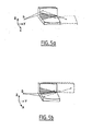
このような光学系は、図2に示すように、「隣接カークパトリック−バエズ」装置の形で製造される。
本文の残り部分において、「カークパトリック−バエズ」構造を「KB」と称する。
従って、この図は、平行して対応する2つのミラー331および332を含む要素33(ミラー331の方向Zと、ミラー332の方向Xとに平行な軸)。
Such an optical system is manufactured in the form of an “adjacent Kirkpatrick-Baez” device, as shown in FIG.
In the remainder of the text, the “Kirk Patrick-Baez” structure is referred to as “KB”.
Thus, this figure shows an element 33 (two axes parallel to the direction Z of the
これら2つのミラーの面は、互いに鉛直な2つの軸上に中心を置く曲率を有している。 The surfaces of these two mirrors have curvatures centered on two axes that are perpendicular to each other.
このタイプの光学系の場合、所望の調整は二重反射によって行われ、各ミラー331、332は1つの軸に沿って一次元の光学効果を生み出す。
For this type of optical system, the desired adjustment is made by double reflection, and each
従って、2つのミラーのそれぞれは、平行化または集束化を行うことができる。 Thus, each of the two mirrors can be collimated or focused.
モノクロメータMは、要素33で反射された光束X2を受ける。 The monochromator M receives the light beam X <b> 2 reflected by the element 33.
このタイプの光学要素33の説明は、米国特許US第6,041,099号公報に記載されている。 A description of this type of optical element 33 is given in US Pat. No. 6,041,099.
なお、調整手段は、2つのミラーが平行に設けられていない「KB」装置の形でも製造されうる。 The adjusting means can also be produced in the form of a “KB” device in which the two mirrors are not provided in parallel.
Goubelミラータイプの調整手段と比較してみると、このような二次元効果を有する調整手段は、モノクロメータの角度容認に対応する入射角の範囲内で、発散初期ビームX1から発する光線の大部分を回収することができる。 Compared with the Goubel mirror type adjusting means, the adjusting means having such a two-dimensional effect is that most of the rays emitted from the divergent initial beam X1 within the range of the incident angle corresponding to the angle acceptance of the monochromator. Can be recovered.
本発明の1つの目的は、このような装置の性能を更に改善することにある。 One object of the present invention is to further improve the performance of such devices.
特に、本発明は、発散初期ビームから最大光束量を集め、また上記のように調整手段を含む装置によって生成されるものよりも優れた単色光束を出力で生成することを目的としている。 In particular, it is an object of the present invention to collect the maximum luminous flux from the divergent initial beam and to produce a monochromatic luminous flux at the output that is superior to that produced by the apparatus including the adjusting means as described above.
従って、特定の目的における本発明は、このような装置の出力での光束を増加させるために、サイズの大きいX線源を活用可能にすることを目的としている。 Accordingly, the present invention for a particular purpose is aimed at making it possible to utilize a large X-ray source in order to increase the luminous flux at the output of such a device.
本発明はまた、このような装置のコンパクト性を改善可能にすることを目的としている。 The present invention also aims to improve the compactness of such devices.
これらの目的を達成するために、本発明は、入射X線ビームを扱うことを意図した光学装置であって、
・モノクロメータ(M)と、
・モノクロメータの目標にビームを適合させるために、反射面が2次元光学効果を生み出すことの可能な入射ビームを調整する光学要素(20)とを具備してなり、前記光学要素が多層構造タイプのX線を反射する面を含んでおり、
前記反射面が単一面で構成され、前記反射面が2つの異なる方向に対応する2つの曲率に従って形成されていることを特徴とする光学装置を提案している。
In order to achieve these objectives, the present invention is an optical device intended to handle an incident X-ray beam comprising:
-Monochromator (M),
An optical element (20) for adjusting the incident beam whose reflecting surface can produce a two-dimensional optical effect in order to adapt the beam to the target of the monochromator, said optical element having a multilayer structure type Including a surface that reflects X-rays of
An optical device is proposed in which the reflecting surface is a single surface, and the reflecting surface is formed according to two curvatures corresponding to two different directions.
この装置の好適ではあるが、限定されない側面は以下の通りである。 The preferred but non-limiting aspects of this device are as follows.
・ 前記単一の反射面が、横方向の勾配を有する多層タイプである。
・ 前記単一の反射面が深さ勾配を含んでいる。
・ 前記反射面が、2つのそれぞれの一次元効果を生み出すために、前記2つの異なる方向のそれぞれにおいて形成される。
・ 前記反射面が、第1の方向においてほぼ円形であり、かつ第2の方向においてほぼ放物線形である幾何学形状を有している。
・ 前記第1の方向が前記光学要素のサジタル[sagittal―矢状方向・球欠]方向であり、また前記第2の方向が前記光学要素のメリジオナル[meridional―子午線・経線]方向である。
・ 前記反射面は、ほぼドーナツ型の幾何学形状[トロイダル形状(troidal geometry)]を有している。
・ 前記反射面は、ほぼ放物面状の幾何学形状[パラボラ形状(paraboloidal geometry)]を有している。
・ 前記反射面は、ほぼ楕円形状(ellipsoidal geometry)の幾何学形状を有している。
・ 前記反射面は、線Cu−Kα(銅カリウム)またはMo−Kα(モリブデンカリウム)の光線を反射することが可能である。
・ 前記モノクロメータがゲルマニウム結晶であり、また前記光学調整要素が横方向の勾配を有するW/Si(タングステン/シリコン)多層被覆から構成される。
・ 前記装置の前記光学要素が約2cmの長さを有しており、約300*300ミクロンのサンプル点を生成するために、前記装置が約数十ミクロン×数十ミクロンの大きさのX線源で使用可能である。
The single reflecting surface is a multilayer type having a lateral gradient.
The single reflecting surface includes a depth gradient;
The reflective surface is formed in each of the two different directions to produce two respective one-dimensional effects.
The reflective surface has a geometric shape that is substantially circular in the first direction and substantially parabolic in the second direction;
The first direction is the sagittal direction of the optical element, and the second direction is the meridional direction of the optical element.
The reflective surface has a generally donut-shaped geometry [troidal geometry];
The reflective surface has a substantially parabolic geometry [paraboloidal geometry];
The reflective surface has a substantially ellipsoidal geometry;
-The said reflective surface can reflect the light ray of line | wire Cu-K (alpha) (copper potassium) or Mo-K (alpha) (molybdenum potassium).
The monochromator is a germanium crystal and the optical tuning element is composed of a W / Si (tungsten / silicon) multilayer coating with a lateral gradient;
The optical element of the device has a length of about 2 cm and the device produces X-rays of about several tens of microns by several tens of microns to produce a sample point of about 300 * 300 microns Available at source.
本発明の他の態様、目的、および効果は、従来技術を参照して述べた図1および2を除く添付図面を参照して、本発明の以下の説明を読むことにより、更に明瞭に明らかとなるであろう。 Other aspects, objects, and advantages of the present invention will become more clearly apparent when the following description of the invention is read with reference to the accompanying drawings, with the exception of FIGS. 1 and 2, described with reference to the prior art. It will be.
なお、この説明の序文として、図面は本発明の原理を図解することを目的としており、必ずしも寸法および尺度を写実的にあらわしていない。 As an introduction to this description, the drawings are intended to illustrate the principles of the present invention and do not necessarily represent dimensions and scales realistically.
このことは、特にX線の入射(あるいは反射でさえも)の角度に対しても真実である。 This is especially true for the angle of incidence (or even reflection) of X-rays.
実際に、これらX線は10°未満の入射角で本発明による反射面に到達する。
メリジオナルおよびサジタル方向も、X線ビームの一般的な伝播方向に対して規定される。
・メリジオナル方向は、このビームの平均伝播方向(更に正確には、関連する光学アセンブリ上の反射の前後におけるビームの平均伝播方向間の平均方向)に相当する。
・サジタル方向は、このメリジオナル方向の水平横方向(ここで、垂直は、後に説明されかつ入射X線ビームを反射させるのに実際に使用される光学アセンブリの反射面の一部に対する平均法線によって定義される)に相当する。
In practice, these X-rays reach the reflecting surface according to the present invention at an incident angle of less than 10 °.
The meridional and sagittal directions are also defined relative to the general propagation direction of the x-ray beam.
The meridional direction corresponds to the average propagation direction of this beam (more precisely, the average direction between the average propagation directions of the beam before and after reflection on the associated optical assembly).
The sagittal direction is the horizontal transverse direction of this meridional direction (where vertical is the average normal to the part of the reflective surface of the optical assembly that will be explained later and actually used to reflect the incident x-ray beam) Defined).
図3を参照すると、本発明による装置が、サンプルEの上流に配置されているのが示されている。
この装置は、
・ある発散を有するX1で示す初期X線ビームを調整する手段と、
・ある角度容認に関連するモノクロメータMとを含んでいる。
Referring to FIG. 3, it can be seen that the device according to the invention is arranged upstream of the sample E.
This device
Means for adjusting the initial X-ray beam denoted X1 having a divergence;
Includes a monochromator M associated with certain angular acceptance.
調整手段は、本発明のこの実施例においては、X線源Sから発せられる初期ビームX1の光線を反射することを目的とする光学要素20の形で製造される。
The adjusting means is manufactured in the form of an
図3の場合、光学要素30は、第1の次元において平行化を行い、かつ第2の異なる次元において焦束を行う。
光源Sは特に、X線管、回転陽極、またはマイクロフォーカスタイプのX線源であってよい。
光学要素20は、(例えばガラス製の)基板上に形成された多層構造体を含んでおり、これはビームX1のX線に対する反射面を規定する。
この光学要素の単一の反射面は、特殊な幾何学形状を有している。
更に正確には、この反射面は、2つの異なる方向に相当する2つの曲率に従って形成されている。
In the case of FIG. 3, the optical element 30 performs collimation in a first dimension and performs focusing in a second different dimension.
The light source S may in particular be an X-ray tube, a rotating anode or a microfocus type X-ray source.
The
The single reflective surface of this optical element has a special geometric shape.
More precisely, the reflecting surface is formed according to two curvatures corresponding to two different directions.
従って、この反射面は、米国特許US第6,041,099号公報に開示されているような光学アセンブリで使用されている種類の反射面に対して著しい違いを有している。
・2つの異なる基本ミラーが取り付けられている光学アセンブリの場合とは異なり、反射面が単一の反射面になっている。
・この反射面は一定である(この用語は、本文では、反射面がいずれの二次不連続部、すなわち角度点または縁部−凸部または凹部−などを示していないことを意味する)。
・更に、重要である違いは、本発明の場合、必要な二次元光学効果を生成するために、入射光線が単一の反射を受けるのみである一方、例えば米国特許US6,041,099号公報の教示を再現する調整手段を使用する光学アセンブリの場合、2回の反射が必要である。
Thus, this reflective surface has a significant difference from the type of reflective surface used in optical assemblies such as that disclosed in US Pat. No. 6,041,099.
Unlike the optical assembly where two different basic mirrors are mounted, the reflective surface is a single reflective surface.
This reflective surface is constant (this term means in the text that the reflective surface does not show any secondary discontinuities, i.e. angular points or edges-projections or recesses-).
-Furthermore, an important difference is that in the case of the present invention, the incident light only undergoes a single reflection to produce the necessary two-dimensional optical effect, while for example US Pat. No. 6,041,099. In the case of an optical assembly that uses adjustment means to reproduce the teachings of, two reflections are required.
本発明において考慮される光学調整要素の説明
図3に示す実施例を詳細に述べる前に、本発明の一般的な特徴を開示する。
DESCRIPTION OF OPTICAL ADJUSTMENT ELEMENTS CONSIDERED IN THE INVENTION Before describing the embodiment shown in FIG. 3 in detail, general features of the invention will be disclosed.
本発明による光学要素の反射面は、サジタル方向Xにおいて曲率Cxを有し、またメリジオナル方向Yにおいて曲率Cyを有している。 The reflective surface of the optical element according to the invention has a curvature Cx in the sagittal direction X and a curvature Cy in the meridional direction Y.
図3はこれらの曲率を示しており、2つの曲率CxおよびCyを破線で示している。 FIG. 3 shows these curvatures, and the two curvatures Cx and Cy are indicated by broken lines.
曲線Cx、Cyのそれぞれは円であってよいが、楕円、放物線、または他の曲線(開または閉)であってもよい。 Each of the curves Cx, Cy may be a circle, but may be an ellipse, a parabola, or another curve (open or closed).
いずれの場合も、光学調整要素の反射面は、単純な球状を有していない。 In any case, the reflecting surface of the optical adjustment element does not have a simple spherical shape.
従って、曲線Cx、Cyのそれぞれは、空間における異なる方向(ここで述べる例では、2つの鉛直方向)に関連している。
また、これら曲線のそれぞれは、反射面で反射されたX線の一次元光学効果を生み出す。
・曲線Cxは、方向Xにおいて一次元光学効果を生み出す。
・曲線Cyは、方向Yにおいて一次元光学効果を生み出す。
また、これら次元効果のそれぞれは、曲線に関連する曲率と、この曲線に沿った変化の法則とに依存している。
従って、集束や一次元平行化などの関連する一次元効果を選択的に得るために、曲線CxおよびCyをパラメータ化することが可能となる。
Accordingly, each of the curves Cx and Cy is related to a different direction in space (in the example described here, two vertical directions).
Each of these curves also produces a one-dimensional optical effect of X-rays reflected by the reflecting surface.
The curve Cx produces a one-dimensional optical effect in the direction X.
The curve Cy produces a one-dimensional optical effect in the direction Y.
Also, each of these dimensional effects depends on the curvature associated with the curve and the law of change along the curve.
Therefore, the curves Cx and Cy can be parameterized to selectively obtain related one-dimensional effects such as focusing and one-dimensional collimation.
図3は、本発明の一実施例を示している。
本実施例において、曲線Cxにより一次元集束が行われ、また曲線Cyによって一次元平行化が行われる。
図3の光学要素20の多層の反射面は、この目的のために、それぞれ円形および放物線形である2つの曲線CxおよびCyにおける各方向XおよびYにおいて形成されており、これら曲線のそれぞれは、面XYおよび面YZにおいてそれぞれ特定の面内で一次元効果を生み出している。
従って、発散ビームX1からは、空間における一次元において平行化がおこなわれ、別の次元では集束が行われる。
FIG. 3 shows an embodiment of the present invention.
In this embodiment, one-dimensional focusing is performed by the curve Cx, and one-dimensional collimation is performed by the curve Cy.
The multilayer reflective surface of the
Accordingly, the diverging beam X1 is collimated in one dimension in space and focused in another dimension.
本発明の変形例によれば、モノクロメータ上で入射ビームを調整する手段は、2つの次元において平行化を行う光学要素でありうる。
この場合、曲線CxおよびCyは共に、放物線として形成される。
図3における本発明の実施例に戻ると、モノクロメータMは、ビームX2の平均方向がモノクロメータの入射角θβに相当するか、あるいはこのモノクロメータの角度容認に対応可能な角度に相当するよう位置している。
このように、このモノクロの角度容認によって規定される許容範囲内でモノクロメータに到達するX線光束は、垂直方向(方向Z)において最大化されるが、サジタル方向においても最大化される。
According to a variant of the invention, the means for adjusting the incident beam on the monochromator can be an optical element that collimates in two dimensions.
In this case, the curves Cx and Cy are both formed as parabolas.
Returning to the embodiment of the present invention in FIG. 3, the monochromator M corresponds to the average direction of the beam X2 corresponding to the incident angle θ β of the monochromator, or to an angle that can correspond to the angle acceptance of the monochromator. Is located so.
As described above, the X-ray beam reaching the monochromator within the allowable range defined by the monochrome angle acceptance is maximized in the vertical direction (direction Z), but is also maximized in the sagittal direction.
ここで述べるべきことは、本発明によれば、(本明細書の後で説明するように、横方向の勾配、また可能であれば深さ勾配も有している)多層ミラーから構成される光学要素を備える調整手段を生成することが可能であり、この多層ミラーの反射面は、反射ビームX2をモノクロメータに再び方向付けるのに必要な機能を満たすことのできる様々な非球面の複雑な形状の中の1つを保有することができる、ということである。
従って、特に、この反射面に以下の幾何学形状のいずれかを与えることができる。
What has to be stated here is that according to the invention it is composed of multilayer mirrors (with lateral gradients and possibly also depth gradients, as explained later in this document). It is possible to produce adjusting means with optical elements, the reflecting surface of this multilayer mirror is a complex of various aspheric surfaces that can fulfill the functions necessary to redirect the reflected beam X2 to the monochromator. It can hold one of the shapes.
Thus, in particular, this reflective surface can be given any of the following geometric shapes:
・ほぼドーナツ型の幾何学形状。
・ほぼ放物面状の幾何学形状。
・ほぼ楕円面状の幾何学形状。
・第1の方向(特にサジタル方向において)においてほぼ円形でありかつ第2の方向(特にメリジオナル方向において)ほぼ放物線形である幾何学形状。
横方向の勾配は、特に入射X線のメリジオナル方向に拡張可能である。
-Almost donut-shaped geometric shape.
-Almost parabolic geometric shape.
-Almost elliptical geometric shape.
A geometric shape that is substantially circular in the first direction (especially in the sagittal direction) and substantially parabolic in the second direction (especially in the meridional direction).
The lateral gradient can be extended especially in the meridional direction of incident X-rays.
また、多層の周期を適合させて、特に線Cu−KαまたはMo−Kαの光線を反射することができる。
サジタル面(すなわち、図3における面XY)において集束を行う本発明の実施例の場合、曲率半径Rx(サジタル曲率半径)は、本発明の好適な一応用例による90cm未満の短い距離(光源−点集束距離)で集束を行うのに必要な20mm未満の値を有することができる。
It is also possible to adapt the multilayer period to reflect in particular the rays Cu-Kα or Mo-Kα.
For embodiments of the present invention that focus on the sagittal plane (ie, plane XY in FIG. 3), the radius of curvature Rx (sagittal radius of curvature) is a short distance (light source-point) less than 90 cm according to one preferred application of the present invention. It can have a value less than 20 mm required for focusing at a focusing distance.
なお、本発明による装置におけるビーム調整手段として使用される光学要素は、KPタイプの光学アセンブリの欠点と制限を無くすものである。特に、
・この光学アセンブリは(扱いにくいアセンブリを必要としない)単一部に存在する。
・入射X線は、その反射面上で単一の反射を受けるのみである。
光学要素20の反射面が多層によって規定されることは上述した。
実際に全ての場合における(本文で扱う全ての多層のように)この多層は、最小の1つの「横方向の勾配」で成り立っている。
この特徴により、要素20の反射面に対して異なる局所入射角を有するX連を効果的に反射することができる。
It should be noted that the optical element used as the beam adjusting means in the apparatus according to the present invention eliminates the disadvantages and limitations of the KP type optical assembly. In particular,
This optical assembly exists in a single part (no need for cumbersome assemblies).
Incident X-rays only receive a single reflection on their reflecting surface.
It has been mentioned above that the reflective surface of the
In fact, in all cases (like all multilayers covered in the text) this multilayer consists of a minimum of one “lateral gradient”.
With this feature, X-series having different local incident angles with respect to the reflecting surface of the
実際に、この反射面上の様々な点が、(入射ビームの発散と、この反射面の幾何学形状のために)同一の局所入射角を有する入射X線を受けることはない。
横方向の勾配を有する多層は、ここでは、ブラッグの条件がミラーの通常の面上のあらゆる点で満たされるように層構造が適合された多層を意味している。
従って、例えば銅のKα線(0.154nmに近い波長を有するCu−Kα線)を含む狭波長帯域における入射X線の放射の場合、横方向に勾配を有する多層ミラーにより、ミラーの通常の面全体でブラッグの条件を維持することが可能である。
これにより、入射光線が可変局所入射角を有するミラーの異なる領域によって、所定の波長(上記例では、銅Kα線を含む)を有する帯域の反射が行われる。
従って、実際に使用されるミラーの面領域を大きくすることができる。
In fact, various points on the reflecting surface will not receive incident x-rays with the same local angle of incidence (due to the divergence of the incident beam and the geometry of the reflecting surface).
Multi-layer with a lateral gradient means here a multi-layer whose layer structure is adapted such that the Bragg condition is fulfilled at every point on the normal face of the mirror.
Thus, in the case of incident X-ray radiation in a narrow wavelength band including, for example, copper Kα radiation (Cu-Kα radiation having a wavelength close to 0.154 nm), a normal surface of the mirror is obtained by a multilayer mirror having a lateral gradient. It is possible to maintain the Bragg condition as a whole.
Thereby, reflection of a band having a predetermined wavelength (including copper Kα rays in the above example) is performed by different regions of the mirror in which the incident light beam has a variable local incident angle.
Accordingly, the surface area of the mirror that is actually used can be increased.
勾配は、ミラー上の位置に応じて多層の周期を変化させることにより得られる。
従って、このタイプの横方向勾配多層構造により、光学アセンブリの立体集光角を大きくすることができるので、全反射において機能する単層ミラーと比較して、同一の幾何学形状に対してより高い反射光束を得ることができる。
しかし、ちなみに、極端な場合、特に光学要素の曲率が小さく、このタイプの勾配を必要としない場合、多層は横方向の勾配を有していなくてもよい。
The gradient is obtained by changing the period of the multilayer depending on the position on the mirror.
Therefore, this type of laterally gradient multi-layer structure allows the stereo collection angle of the optical assembly to be increased, which is higher for the same geometry compared to a single layer mirror that functions in total reflection. A reflected light beam can be obtained.
However, in extreme cases, especially if the curvature of the optical element is small and this type of gradient is not required, the multilayer may not have a lateral gradient.
本発明の様々な実施例の多層は、深さ勾配も有していてよい。
このような深さ勾配により、固定入射角および可変波長、あるいは可変入射角および固定波長に対してブラッグの条件を満たすことが可能である。
従って、1つの同一の特定の像平面(固定幾何学形状の場合−つまり、入射光線源と、光学アセンブリと、像平面との相対位置が一定である構造)で、例えば、光学アセンブリの多層の波長帯域幅を広げ、また異なる波長を有するX線を集束あるいは平行化することが可能である。
The multilayers of the various embodiments of the present invention may also have a depth gradient.
With such a depth gradient, it is possible to satisfy the Bragg condition for a fixed incident angle and a variable wavelength, or for a variable incident angle and a fixed wavelength.
Thus, in one identical specific image plane (in the case of a fixed geometry—that is, a structure where the relative positions of the incident light source, the optical assembly, and the image plane are constant), for example, multiple layers of the optical assembly It is possible to broaden the wavelength bandwidth and to focus or collimate X-rays with different wavelengths.
このように、光学アセンブリに対して光源および/または単一あるいは複数の像平面を新たに位置合わせする必要なく、異なる波長を有するX線源を使用して、同一の光学アセンブリで様々な光源から発せられるX線を反射させることができる。
この場合、光学アセンブリの波長における許容範囲(Δλにおける許容範囲)が使用される。
同様に、このΔλにおける許容範囲をΔθにおける許容範囲に変換することも可能であり、θは要素20の入射角である。
実際、波長の許容範囲は、ブラッグの条件に照らして、入射角の許容範囲に対応するので、入射ビームの一定波長の場合、同一波長の光線が異なる局所入射角を有する入射光束を集光および反射することが可能である。
特に、このように、大きなサイズ(光学構成要素の角度容認の増大)のX線源を使用することができる。
従って、多層において深さ勾配を有する調整手段を生成することにより、本発明を実施する1つの選択が得られる。
In this way, X-ray sources having different wavelengths can be used from the various optical sources in the same optical assembly without the need to re-align the light source and / or single or multiple image planes with respect to the optical assembly. X-rays emitted can be reflected.
In this case, the tolerance in the wavelength of the optical assembly (tolerance in Δλ) is used.
Similarly, the allowable range at Δλ can be converted into an allowable range at Δθ, where θ is the incident angle of the
In fact, the acceptable range of wavelengths corresponds to the acceptable range of incident angles in light of Bragg's conditions, so that, for a given wavelength of the incident beam, rays of the same wavelength collect incident beams with different local angles of incidence and It is possible to reflect.
In particular, X-ray sources of large size (increased angular tolerance of optical components) can thus be used.
Thus, by generating an adjustment means having a depth gradient in the multilayer, one choice of implementing the invention is obtained.
二次元調整手段の情報
モノクロメータ上の入射放射を調整する二次元光学系を使用することにより、モノクロメータの基準面上で固定入射角を維持するために第1の次元で平行化を行い、また一方で最大入射光束を集めるために(サジタル面XYで規定される)第2の次元で第2の一次元効果を生み出すことが可能である。
Information on the two-dimensional adjustment means By using a two-dimensional optical system that adjusts the incident radiation on the monochromator, parallelization is performed in the first dimension to maintain a fixed incident angle on the reference plane of the monochromator, On the other hand, it is possible to produce a second one-dimensional effect in the second dimension (as defined by the sagittal plane XY) in order to collect the maximum incident luminous flux.
第2の次元における調整は、集束または平行化である。
例として、このような機能を図3に示す。(調整手段20によって反射される)ビームX2に対して、モノクロメータの角度容認における約θβの入射角を維持するために、面YZにおいて面YZの発散光線が平行化される。
光学要素20によって行われる第1の次元による平行化機能により、回折面におけるビームの角発散を制限することができる(各反射X線の場合、回折面は、入射ビームと反射ビームとを含む反射面に垂直な面として定義される)。
サンプルで集められるX線光束を増加させる目的で、例えば、図3の場合のXY面(サジタル面)上において、第2の次元の調整を行うことは効果的である。
The adjustment in the second dimension is focusing or collimation.
As an example, such a function is shown in FIG. Against (as reflected by the adjustment means 20) beam X2, in order to maintain the angle of incidence of about theta beta in the angular acceptance of the monochromator, divergence beam plane YZ is collimated in the plane YZ.
The collimating function by the first dimension performed by the
For the purpose of increasing the X-ray beam collected by the sample, for example, it is effective to perform the second dimension adjustment on the XY plane (sagittal plane) in the case of FIG.
これにより、この面における発散を制限することができるので、光源から集められ、モノクロメータでの反射後にサンプルで投射されるX線光束を最大化することが可能になる。 This can limit the divergence on this surface, thereby maximizing the X-ray flux collected from the light source and projected on the sample after reflection by the monochromator.
(やはり図3を参照して)第2の次元におけるこの調整が行われる一方で、モノクロメータの動作状態を確実にする(回折面における角発散を制限する)。上述したように、第2の次元における調整は集束または平行化であってよい。 While this adjustment in the second dimension is made (again referring to FIG. 3), it ensures the operating state of the monochromator (limits the angular divergence at the diffractive surface). As mentioned above, the adjustment in the second dimension may be focusing or collimation.
集束を行うことによる第2の方向(サジタル)における光束の増加が可能となることは、当該応用例の場合にモノクロメータでのサジタル面において容認された角発散αが大きくなるので、とりわけ有利である。
これは、(直面する集束条件および当該モノクロメータの種類に対して)本発明の応用分野の場合、モノクロメータ上の入射X線の入射角に対して、第2の次元(サジタル次元)における発散αはあまり影響を持たないためである。
The ability to increase the luminous flux in the second direction (sagittal) by performing focusing is particularly advantageous because the angular divergence α accepted in the sagittal plane of the monochromator increases in the case of the application. is there.
For the field of application of the present invention (for the focusing conditions encountered and the type of monochromator concerned), this is the divergence in the second dimension (sagittal dimension) relative to the angle of incidence of the incident X-rays on the monochromator. This is because α has little influence.
図4を参照すると、サジタル面における発散αは、(例えば光学系の中心で決まる)同一面における調整光学系XIの有用幅と、集束距離dFOC(光学系−像点距離)とによって与えられる。従って、方向Xにおける発散αは以下の式によって近似させることが可能である。
Tan(α)=((XI/2−L/2)/(dFOC))、ここでLはサジタル面における像点の幅である。
サジタル面における発散α(Δαと呼ぶ)のモノクロメータの角度許容範囲が、ブラッグ角θβとこのモノクロメータの角度容認Δθとの関数であることが知られている。M.SchusterおよびH.Goubelによる文書、J.Phys.D:応用物理28(1995)A270〜A275「テーラード多層を使用したチャネルカットモノクロメータに結合される平行ビーム」を参照すると、この角度許容範囲Δαは以下のように表される。
Referring to FIG. 4, the divergence α in the sagittal plane, (e.g., determined by the center of the optical system) and useful width of the adjustment optical system X I in the same plane, the focusing distance d FOC - given by the (optical image point distance) It is done. Accordingly, the divergence α in the direction X can be approximated by the following equation.
Tan (α) = ((X I / 2−L / 2) / (d FOC )), where L is the width of the image point on the sagittal plane.
It is known that the angle tolerance range of the monochromator for the divergence α (referred to as Δα) on the sagittal plane is a function of the Bragg angle θ β and the angle tolerance Δθ of the monochromator. M.M. Schuster and H.C. A document by Goubel, J.M. Phys. D: Applied Physics 28 (1995) A270-A275 “Parallel beam coupled to channel cut monochromator using tailored multilayers”, this angular tolerance Δα is expressed as follows:
((Δθ/tanθβ)*2)1/2=Δα、この式において、ΔαおよびΔθはラジアンで表される。 ((Δθ / tan θ β ) * 2) 1/2 = Δα, where Δα and Δθ are expressed in radians.
従って、サジタル面における角発散の許容範囲は、例えばCu−Kα応用例のゲルマニウム結晶に対して決定される(θβ=22.65°、Δθ=0.00336°)。
従って、1°オーダーの制限発散(ビームX2の発散の角度許容範囲)が計算され、これは本発明の応用分野に必要な収束よりもかなり上である。
その結果、モノクロメータは、当該第2の方向(図3における方向X)における入射ビームX2の更に多くの発散を受けることができる。
そのため、当該第2の方向(サジタル方向)に対して、光源からの最大光束量を集めることは有利である。
この一般的な目的は、本発明による装置と、調整手段、KBタイプの光学アセンブリを機知の方法で使用する装置とに関連している。
KBタイプの調整手段を含む装置と比較したときの特定の利点についての別の主要部分
当該第2の方向において、つまり、モノクロメータが更に多くの発散を許容する方向(図3の場合、方向X)において、多層被覆を有する「KBタイプ」(隣接している、あるいはしていない)の二次元光学アセンブリによって、初期ビーム調整を実施する装置と比較すると、本発明は光源から更に多くの光束を集めることができる。
Therefore, the allowable range of angular divergence in the sagittal plane is determined, for example, for the germanium crystal of the Cu-Kα application example (θ β = 22.65 °, Δθ = 0.00336 °).
Therefore, a limit divergence on the order of 1 ° (angle tolerance of the divergence of beam X2) is calculated, which is well above the convergence required for the application field of the invention.
As a result, the monochromator can receive more divergence of the incident beam X2 in the second direction (direction X in FIG. 3).
Therefore, it is advantageous to collect the maximum light flux from the light source in the second direction (sagittal direction).
This general object relates to the device according to the invention and to the adjustment means, the device using the KB type optical assembly in a known manner.
Another major part of the particular advantage when compared with a device comprising a KB type adjustment means In this second direction, ie the direction in which the monochromator allows more divergence (in the case of FIG. 3, direction X ) With a “KB type” (adjacent or not) two-dimensional optical assembly with a multi-layer coating, the present invention allows more light flux from the light source compared to a device that performs initial beam conditioning. Can be collected.
2つの現象によりこのゲインを光束に生じさせるが、これら現象について以下に説明する。
・まず、(メリジオナル方向における)特定の長さを有する要素20などの光学要素を有する本発明の場合、サジタル方向において捕獲角度が得られるが、これはKB光学系によって調整を実施する従来の構造で得られる角度よりも大きい。
・第二に、本発明で使用されているような二次元光学要素20はサジタル方向において初期ビームX1のより多くの発散を受けることができるので、この要素20上の何れの点においても大きな光源面を得ることができる。
これは、上述した第1のタイプも参照すると、KBタイプの光学アセンブリで行われる調整の場合、光学アセンブリ上のビームの平均伝播方向を横切る方向において立体集光角を大きくするために、この光学アセンブリの長さを大きくする必要があるからである。
これは、KB構造による二次元効果を得ることは、二重反射と密接な関係にあるためである。
実例として、また図2を考察すると、装置をXまたはZ方向に拡張する場合、ミラーをY方向に拡張する必要がある。
This gain is caused in the light flux by two phenomena, which will be described below.
First, in the case of the present invention with an optical element such as
Second, the two-dimensional
This also refers to the first type described above, in the case of adjustments made with a KB type optical assembly, this optical to increase the solid collection angle in the direction transverse to the average propagation direction of the beam on the optical assembly. This is because it is necessary to increase the length of the assembly.
This is because obtaining a two-dimensional effect by the KB structure is closely related to double reflection.
Illustratively and considering FIG. 2, if the device is expanded in the X or Z direction, the mirror needs to be expanded in the Y direction.
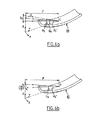
この現象を、図5aおよび5bに示す。
実際、KBタイプの光学要素の場合、二重反射されるためには、何れの入射光線も(図5aおよび5bにおけるハッチングを施した領域に相当する)特定の領域の光学系に入射しなければならない。
従って、その結果として、このような既知のタイプの光学調整要素の場合(ミラーは連続または不連続である)、集められる立体角は、水平横断方向と垂直横断方向(方向Zまたは方向X)の両者に対する構成要素の長さによって制限される。
This phenomenon is illustrated in FIGS. 5a and 5b.
In fact, in the case of a KB type optical element, in order to be double-reflected, any incident light beam must enter the optical system in a specific area (corresponding to the hatched area in FIGS. 5a and 5b). Don't be.
Consequently, as a result, for such known types of optical adjustment elements (mirrors are continuous or discontinuous), the collected solid angles are in the horizontal and vertical transverse directions (direction Z or X). Limited by the length of the component for both.
KBタイプの光学アセンブリの場合、従って、(メリジオナル方向における)構成要素の長さは、立体集光角の横方向の構成要素と縦方向の構成要素の両方に影響を及ぼす。
本発明の場合、装置の長さを大きくすることなく、サジタル方向における立体集光角を大きくすることができる。
これは特に、光学系の体積と寸法を制限したい場合に重要である。
使用する光源が数十ミクロン×数十ミクロン(例えば40ミクロン×40ミクロン)のサイズを有するX線マイクロ光源であり、また分析するサンプル点が100ミクロン×100ミクロンオーダー(例えば300ミクロン×300ミクロン)であるマイクロエレクトロニクスのX線マイクロマッピングの応用例としては、これは特に当てはまる。
In the case of a KB type optical assembly, the length of the component (in the meridional direction) therefore affects both the lateral and longitudinal components of the solid collection angle.
In the case of the present invention, the three-dimensional condensing angle in the sagittal direction can be increased without increasing the length of the apparatus.
This is particularly important when it is desired to limit the volume and dimensions of the optical system.
The light source used is an X-ray micro light source having a size of several tens of microns × several tens of microns (for example, 40 microns × 40 microns), and the sample point to be analyzed is on the order of 100 microns × 100 microns (for example, 300 microns × 300 microns). This is especially true for applications of X-ray micromapping in microelectronics.
この場合、光学調整要素の長さを約2cmに制限することが望ましい。
また、大まかに言えば、装置の長さを制限することが求められる応用例の場合、本発明で使用する光学系の組み合わせは特に有利となり、またモノクロメータによって反射される光束を最大化する一方で、装置のサイズを最小に抑えることができる。
また、(光学系上のX線の平均伝播方向である)メリジオナル方向における調整ミラーの拡張は、横方向の勾配が与えられる多層面を広げるという効果を有する。
このタイプの勾配は、光学構成要素の面の曲率を補償するために与えられる。
In this case, it is desirable to limit the length of the optical adjustment element to about 2 cm.
Roughly speaking, in the case of an application in which it is required to limit the length of the apparatus, the combination of optical systems used in the present invention is particularly advantageous, while maximizing the luminous flux reflected by the monochromator. Thus, the size of the apparatus can be minimized.
Also, the extension of the adjustment mirror in the meridional direction (which is the average propagation direction of X-rays on the optical system) has the effect of widening the multilayer surface to which a lateral gradient is applied.
This type of gradient is provided to compensate for the curvature of the surface of the optical component.
図5aおよび5bにおいて、多層の勾配は、光学アセンブリの2つのミラーに対するY軸に沿って与えられる。
その結果、構成要素の長さを大きくすると、勾配が与えられる面が大きくなり、これにより、装置の製造が更に複雑になる。
本発明で考察されているような単一の反射を行う調整光学系の場合、例えば光学系の入口と出口に位置される取外し可能スロットのサイズを単に大きくすることによって、立体集光角をサジタル方向において大きくすることができる。
In FIGS. 5a and 5b, a multilayer gradient is provided along the Y axis for the two mirrors of the optical assembly.
As a result, increasing the length of the component increases the surface on which the gradient is applied, which further complicates the manufacture of the device.
In the case of an adjusting optical system with a single reflection as discussed in the present invention, the solid collection angle is sagittal, for example by simply increasing the size of the removable slots located at the entrance and exit of the optical system. Can be larger in the direction.
本発明の別の利点は、光学調整アセンブリ上の何れの点においてもより大きな光源面を得ることができ、そのため像点における光束を最大化できることにある。
図6aおよび6b、および図2は、これらの図において規定される面XZに面が平行であるX線源を考察する場合のこの現象を示している。
図6aおよび6bは、本発明で使用されているような光学調整要素20を示している。
Another advantage of the present invention is that a larger light source surface can be obtained at any point on the optical adjustment assembly, thus maximizing the luminous flux at the image point.
FIGS. 6a and 6b and FIG. 2 illustrate this phenomenon when considering an X-ray source whose plane is parallel to the plane XZ defined in these figures.
Figures 6a and 6b show an
図6aおよび6b、および図2による様々な光学系の配置を考慮すると、本発明で考察するような光学調整要素の場合、光学系上の何れかの点でサジタル方向において許容されている入射X線の角発散は、同一方向(すなわち方向X)におけるKBタイプの調整光学要素の許容されている角発散と比べると、比較的大きい。
光源の別の次元(すなわち方向Z)に沿って、2種類の二次元効果光学系上の何れかの点で許容される角発散は非常に近接しており、多層の角度容認によって制限される。
光源の中心SからのX線放射源点のZ方向への移動は、当該光学系の種類が何れであっても(KBタイプまたは本発明で考察されているような単一反射の光学系)、二次元光学要素上の何れの点でのこれらX線の入射角に直接的かつ著しく影響を及ぼす。
本発明で考察されているような光学調整要素の場合、図6aおよび6bを参照すると、光源の中心からの直接ビームと比較される(サジタル方向に相当する)方向Xにおける放射ビームの開きにより、光学系上の何れの点においても入射角がわずかに変化するのみである。
これら図6aおよび6bを参照すると、調整光学要素の中心Cでの入射X線の許容角発散を決定することができる。
Considering the arrangement of the various optical systems according to FIGS. 6a and 6b and FIG. 2, in the case of an optical adjusting element as considered in the present invention, the incident X allowed in the sagittal direction at any point on the optical system. The angular divergence of the line is relatively large compared to the allowed angular divergence of the KB type adjusting optical element in the same direction (ie direction X).
Along the other dimension of the light source (ie, direction Z), the angular divergence allowed at any point on the two types of two-dimensional effect optics is very close and limited by multilayer angular acceptance. .
The movement of the X-ray radiation source point from the center S of the light source in the Z direction is any type of optical system (KB type or single reflection optical system as discussed in the present invention). , Which directly and significantly affects the angle of incidence of these X-rays at any point on the two-dimensional optical element.
In the case of an optical adjustment element as discussed in the present invention, with reference to FIGS. 6a and 6b, the opening of the radiation beam in direction X (corresponding to the sagittal direction) compared to the direct beam from the center of the light source The incident angle only slightly changes at any point on the optical system.
With reference to these FIGS. 6a and 6b, the allowable angular divergence of the incident X-ray at the center C of the adjusting optical element can be determined.
光学系の中心で効果的に反射可能な方向Zにおける光源サイズは、以下の式によって与えられる。
ZI=(cosθS*p)(tanθI−tanθI,)、ここでpは光源の中心と光学系の中心との間の距離、θSは光源の中心Sから発せられる光線の光学系上の入射角、またθIおよびθI,は多層の角度容認によって与えられる限界入射角である(Δθ=θI−θI,)。
The light source size in the direction Z that can be effectively reflected at the center of the optical system is given by the following equation.
ZI = (cosθ S * p) (tanθ I -tanθ I,), where p is the distance between the centers of the optical system of the light source, theta S on the optical system of the light beam emitted from the center S of the light source , And θ I and θ I , are the limit incident angles given by the multilayer angle acceptance (Δθ = θ I −θ I ).
図6aおよび6bを参照すると、方向Xの場合、光学系の中心Cで反射可能な光源サイズは、以下の式で与えられる。
XI=2((p sin θS/tan θI,)2−(p cos θS)2)1/2
上記で与えられている数値XIおよびZIは、多層の角度容認の制限内で決定される光源サイズである。
例として、銅Kα応用例で使用されているW/Si被覆の場合、(光学調整要素20の)多層の角度容認は、1.26°の角度に関しては0.052°である。
また、光源の中心から発せられるビームの光学系上での入射角θSが多層のブラッグ角で与えられるよう、光学系と光源を配置することも考えられる。
12cmの標準光源−光学系距離の場合、本発明で考慮されているように光学系の中心でサジタル方向において集光可能な光源サイズは5cmオーダーであり、また方向Zに対しては約110ミクロンである。
Referring to FIGS. 6a and 6b, for the direction X, the light source size that can be reflected by the center C of the optical system is given by the following equation.
X I = 2 ((p sin θ S / tan θ I ,) 2 − (p cos θ S ) 2 ) 1/2
The numerical values X I and Z I given above are light source sizes determined within the limits of multilayer angular acceptance.
As an example, for the W / Si coating used in copper Kα applications, the multilayer angular acceptance (of the optical tuning element 20) is 0.052 ° for an angle of 1.26 °.
It is also conceivable to arrange the optical system and the light source so that the incident angle θ S on the optical system of the beam emitted from the center of the light source is given by a multilayer Bragg angle.
For a standard light source-optical system distance of 12 cm, the light source size that can be collected in the sagittal direction at the center of the optical system is on the order of 5 cm as considered in the present invention, and about 110 microns for the direction Z. It is.
また、例として、多層のタイプと光源−光学系距離が同一のKB光学アセンブリの場合、特定の点において効果的に集光可能な光源サイズは、考慮する2つの方向(図2を参照してXおよびZ)に対して約110ミクロンに制限される。これを説明する理由については後に述べる。
上記の数値は、比較した光学調整要素によって許容されうる入射ビームの角発散の(W/S多層の上記場合における)理論上の制限を構成している。
しかし、本発明による装置の場合、像点で集められる光束を最終的に最大化するために、サジタル方向におけるモノクロメータによって許容される発散の他に、得ようとする像に関連する仕様(サイズ、距離)も考慮しなければならない。
これらを考慮すると、本発明で考察される光学調整要素の光源から獲得される光束の潜在的ゲインは重要である。
As an example, in the case of a KB optical assembly having the same multilayer type and the same light source-optical system distance, the size of the light source that can be effectively collected at a specific point is determined in two directions (see FIG. 2). Limited to about 110 microns for X and Z). The reason for explaining this will be described later.
The above figures constitute the theoretical limit (in the above case of the W / S multilayer) of the angular divergence of the incident beam that can be tolerated by the compared optical tuning element.
However, in the case of the device according to the invention, in addition to the divergence allowed by the monochromator in the sagittal direction in order to ultimately maximize the light flux collected at the image point, the specification (size) associated with the image to be obtained. , Distance) must also be considered.
In view of these, the potential gain of the luminous flux obtained from the light source of the optical adjustment element considered in the present invention is important.
実際、光学調整アセンブリ上のある点において、例えばX線源とこの光学調整アセンブリとの間の距離が12cmで、300ミクロン×300ミクロンのサイズの標準X線源について考慮してみると、KB光学アセンブリの調整による既知の装置の場合よりも、サジタル方向における光源の面積が大きくなっているのが分かる。
従って、本発明の場合、光学系上の何れの点においてもサジタル方向において300ミクロンの光源を集めることができ、これは、例えば光学系から40cmの所に位置する1mm幅の像点など、必要な像点がサジタル方向において比較的幅広い場合に確かな利点であることを表している。
従って、本発明による装置が、特定の方向において、光源から発せられるビームX1の比較的大きな発散を許容していることが理解されよう。これは、KBタイプの調整要素を使用する既知の装置には当てはまらない。
In fact, at some point on the optical conditioning assembly, considering for example a standard X-ray source of size 300 microns x 300 microns with a distance of 12 cm between the X-ray source and the optical conditioning assembly, KB optics It can be seen that the area of the light source in the sagittal direction is larger than in the case of known devices by adjusting the assembly.
Therefore, in the case of the present invention, it is possible to collect a light source of 300 microns in the sagittal direction at any point on the optical system, such as a 1 mm wide image point located 40 cm from the optical system. This represents a certain advantage when the image point is relatively wide in the sagittal direction.
It will therefore be appreciated that the device according to the invention allows a relatively large divergence of the beam X1 emitted from the light source in a particular direction. This is not the case with known devices using KB type adjustment elements.
図2およびKB光学系を参照すると、第1の水平ミラー332の光学系上のある点で効果的に反射される入射ビームの発散に特定の自由度を与える方向は、垂直ミラー331である第2の光学系の中心に鉛直な方向である。
しかし、2つのミラーを有するこの既知の構成の場合、ミラーの面に垂直またはほぼ垂直な方向は、入射ビームの発散によって入射角が著しく変化する方向に相当する。
従って、KBタイプのアセンブリ上のある点で制御可能な光源サイズは、二重反射現象により、光源の2つの次元に対する多層の角度容認によって制限される。本発明はまた、この制限も無くすものである。
Referring to FIG. 2 and the KB optical system, the direction that gives a certain degree of freedom to the divergence of the incident beam that is effectively reflected at a point on the optical system of the first
However, in this known configuration with two mirrors, the direction perpendicular or nearly perpendicular to the plane of the mirror corresponds to the direction in which the incident angle changes significantly due to the divergence of the incident beam.
Thus, the light source size that can be controlled at a certain point on the KB type assembly is limited by the multilayer angle tolerance for the two dimensions of the light source due to the double reflection phenomenon. The present invention also eliminates this limitation.
Claims (12)
モノクロメータ(M)と、
前記モノクロメータの目標にビームを適合させるために、反射面が2次元光学効果を生み出すことの可能な入射ビームを調整する光学要素(20)と、
を具備し、前記光学要素が多層構造タイプのX線に対する反射型の面を含んでおり、
前記反射面が単一面で構成され、前記反射面が2つの異なる方向に対応する2つの曲率に従って形成されていることを特徴とする光学装置。 An optical device intended to handle an incident X-ray beam,
Monochromator (M),
An optical element (20) for adjusting the incident beam whose reflective surface can produce a two-dimensional optical effect to adapt the beam to the target of the monochromator;
Wherein the optical element includes a reflective surface for multilayer structure type X-rays,
The optical apparatus is characterized in that the reflective surface is a single surface, and the reflective surface is formed according to two curvatures corresponding to two different directions.
Applications Claiming Priority (3)
| Application Number | Priority Date | Filing Date | Title |
|---|---|---|---|
| FR0207546A FR2841371B1 (en) | 2002-06-19 | 2002-06-19 | OPTICAL ASSEMBLY AND ASSOCIATED METHOD |
| FR0300623A FR2850171B1 (en) | 2003-01-21 | 2003-01-21 | OPTICAL DEVICE FOR X-RAY APPLICATIONS |
| PCT/FR2003/001879 WO2004001769A1 (en) | 2002-06-19 | 2003-06-19 | Optical device for x-ray applications |
Publications (2)
| Publication Number | Publication Date |
|---|---|
| JP2005530168A true JP2005530168A (en) | 2005-10-06 |
| JP2005530168A5 JP2005530168A5 (en) | 2006-08-03 |
Family
ID=30001927
Family Applications (2)
| Application Number | Title | Priority Date | Filing Date |
|---|---|---|---|
| JP2004514950A Pending JP2005530168A (en) | 2002-06-19 | 2003-06-19 | X-ray optical device |
| JP2004514960A Pending JP2005530170A (en) | 2002-06-19 | 2003-06-19 | Optical assembly and manufacturing method thereof |
Family Applications After (1)
| Application Number | Title | Priority Date | Filing Date |
|---|---|---|---|
| JP2004514960A Pending JP2005530170A (en) | 2002-06-19 | 2003-06-19 | Optical assembly and manufacturing method thereof |
Country Status (8)
| Country | Link |
|---|---|
| US (2) | US7430277B2 (en) |
| EP (3) | EP1732087A3 (en) |
| JP (2) | JP2005530168A (en) |
| CN (2) | CN1324613C (en) |
| AT (2) | ATE341083T1 (en) |
| AU (2) | AU2003260613A1 (en) |
| DE (3) | DE20320792U1 (en) |
| WO (2) | WO2004001770A1 (en) |
Cited By (5)
| Publication number | Priority date | Publication date | Assignee | Title |
|---|---|---|---|---|
| US7646849B2 (en) | 2006-07-07 | 2010-01-12 | Rigaku Corporation | Ultra-small angle x-ray scattering measuring apparatus |
| JP2010014418A (en) * | 2008-07-01 | 2010-01-21 | Japan Atomic Energy Agency | Multilayer film grating spectroscope |
| JP2014149293A (en) * | 2013-01-30 | 2014-08-21 | Bruker Axs Gmbh | Xrf measuring apparatus for detecting contaminant on bevel of wafer |
| WO2022153979A1 (en) * | 2021-01-12 | 2022-07-21 | 国立大学法人東京大学 | Design method for mirror and astigmatism-control mirror having reflective surface that satisfies design formula in design method |
| WO2022153978A1 (en) * | 2021-01-12 | 2022-07-21 | 国立大学法人東京大学 | Mirror design method, and astigmatism control mirror having reflection surface on which design equation in said method is established |
Families Citing this family (28)
| Publication number | Priority date | Publication date | Assignee | Title |
|---|---|---|---|---|
| US20030199425A1 (en) * | 1997-06-27 | 2003-10-23 | Desai Neil P. | Compositions and methods for treatment of hyperplasia |
| DE10254026C5 (en) * | 2002-11-20 | 2009-01-29 | Incoatec Gmbh | Reflector for X-radiation |
| US20060040091A1 (en) | 2004-08-23 | 2006-02-23 | Bletsos Ioannis V | Breathable low-emissivity metalized sheets |
| DE102005057700A1 (en) * | 2005-11-25 | 2007-06-06 | Axo Dresden Gmbh | X-ray optical element |
| FR2918501B1 (en) | 2007-07-02 | 2009-11-06 | Xenocs Soc Par Actions Simplif | DEVICE FOR DELIVERING A HIGH ENERGY X-RAY BEAM |
| US7706503B2 (en) * | 2007-11-20 | 2010-04-27 | Rigaku Innovative Technologies, Inc. | X-ray optic with varying focal points |
| ATE545858T1 (en) * | 2007-12-31 | 2012-03-15 | Xenocs S A | X-RAY APPARATUS |
| US7741626B2 (en) * | 2008-09-12 | 2010-06-22 | Cymer, Inc. | Spectral purity filters and methods therefor |
| US8050380B2 (en) * | 2009-05-05 | 2011-11-01 | Media Lario, S.R.L. | Zone-optimized mirrors and optical systems using same |
| US8249220B2 (en) * | 2009-10-14 | 2012-08-21 | Rigaku Innovative Technologies, Inc. | Multiconfiguration X-ray optical system |
| US8208602B2 (en) * | 2010-02-22 | 2012-06-26 | General Electric Company | High flux photon beams using optic devices |
| US8311184B2 (en) | 2010-08-30 | 2012-11-13 | General Electric Company | Fan-shaped X-ray beam imaging systems employing graded multilayer optic devices |
| US8488740B2 (en) * | 2010-11-18 | 2013-07-16 | Panalytical B.V. | Diffractometer |
| FR2967887B1 (en) | 2010-11-26 | 2018-01-19 | General Electric Company | COMPACT MAMMOGRAPH, AND ASSOCIATED MAMMOGRAPHING METHOD |
| US8744048B2 (en) | 2010-12-28 | 2014-06-03 | General Electric Company | Integrated X-ray source having a multilayer total internal reflection optic device |
| KR101332502B1 (en) * | 2011-06-14 | 2013-11-26 | 전남대학교산학협력단 | An X-ray Needle Module for Local Radiation Therapy |
| US8761346B2 (en) | 2011-07-29 | 2014-06-24 | General Electric Company | Multilayer total internal reflection optic devices and methods of making and using the same |
| CN102903413B (en) * | 2012-10-30 | 2015-06-03 | 同济大学 | Four-channel KB microimaging system working under small-size backlight |
| US20140161233A1 (en) | 2012-12-06 | 2014-06-12 | Bruker Axs Gmbh | X-ray apparatus with deflectable electron beam |
| EP2896960B1 (en) * | 2014-01-15 | 2017-07-26 | PANalytical B.V. | X-ray apparatus for SAXS and Bragg-Brentano measurements |
| JP6202684B2 (en) * | 2014-06-05 | 2017-09-27 | 株式会社リガク | X-ray diffractometer |
| JP6069609B2 (en) * | 2015-03-26 | 2017-02-01 | 株式会社リガク | Double-curved X-ray condensing element and its constituent, double-curved X-ray spectroscopic element and method for producing the constituent |
| CN105092618A (en) * | 2015-09-18 | 2015-11-25 | 北京师范大学 | X-ray diffractometer achieving microbeam energy dispersion and use method thereof |
| CN105873344A (en) * | 2016-03-22 | 2016-08-17 | 中国工程物理研究院流体物理研究所 | Transverse gradient multi-layer film reflective element based X-ray monoenergetic imaging method |
| US10677744B1 (en) * | 2016-06-03 | 2020-06-09 | U.S. Department Of Energy | Multi-cone x-ray imaging Bragg crystal spectrometer |
| FR3059434B1 (en) * | 2016-11-29 | 2019-05-17 | Centre National De La Recherche Scientifique - Cnrs | SPECTRAL SELECTION COMPONENT FOR XUV RADIATIONS |
| CN106706157B (en) * | 2017-01-11 | 2023-06-13 | 中国工程物理研究院激光聚变研究中心 | ICF hot spot electronic temperature detection equipment based on quasi-synoptic axis |
| WO2020260336A1 (en) * | 2019-06-24 | 2020-12-30 | Sms Group Gmbh | Controlling the process parameters by means of radiographic online determination of material properties when producing metallic strips and sheets |
Family Cites Families (18)
| Publication number | Priority date | Publication date | Assignee | Title |
|---|---|---|---|---|
| NL8300421A (en) | 1983-02-04 | 1984-09-03 | Philips Nv | ROENTGEN RESEARCH DEVICE WITH DOUBLE FOCUSING CRYSTAL. |
| US4599741A (en) * | 1983-11-04 | 1986-07-08 | USC--Dept. of Materials Science | System for local X-ray excitation by monochromatic X-rays |
| US4562583A (en) | 1984-01-17 | 1985-12-31 | The United States Of America As Represented By The Administrator Of The National Aeronautics And Space Administration | Spectral slicing X-ray telescope with variable magnification |
| GB2217036B (en) * | 1988-03-11 | 1992-08-12 | Rosser Roy J | Saddle toroid mirrors |
| US5127028A (en) | 1990-08-01 | 1992-06-30 | Wittry David B | Diffractord with doubly curved surface steps |
| US5142561A (en) * | 1991-05-28 | 1992-08-25 | Grumman Aerospace Corporation | X-ray lithography scanning mirror |
| US5373544A (en) * | 1992-08-12 | 1994-12-13 | Siemens Aktiengesellschaft | X-ray diffractometer |
| US5646976A (en) * | 1994-08-01 | 1997-07-08 | Osmic, Inc. | Optical element of multilayered thin film for X-rays and neutrons |
| US5619548A (en) | 1995-08-11 | 1997-04-08 | Oryx Instruments And Materials Corp. | X-ray thickness gauge |
| DE19615366B4 (en) * | 1996-04-19 | 2006-02-09 | Carl Zeiss Jena Gmbh | Method and device for detecting physical, chemical, biological or biochemical reactions and interactions |
| US6041099A (en) | 1998-02-19 | 2000-03-21 | Osmic, Inc. | Single corner kirkpatrick-baez beam conditioning optic assembly |
| DE19833524B4 (en) | 1998-07-25 | 2004-09-23 | Bruker Axs Gmbh | X-ray analyzer with gradient multilayer mirror |
| US6285506B1 (en) | 1999-01-21 | 2001-09-04 | X-Ray Optical Systems, Inc. | Curved optical device and method of fabrication |
| US6278764B1 (en) | 1999-07-22 | 2001-08-21 | The Regents Of The Unviersity Of California | High efficiency replicated x-ray optics and fabrication method |
| US6317483B1 (en) * | 1999-11-29 | 2001-11-13 | X-Ray Optical Systems, Inc. | Doubly curved optical device with graded atomic planes |
| US6829327B1 (en) * | 2000-09-22 | 2004-12-07 | X-Ray Optical Systems, Inc. | Total-reflection x-ray fluorescence apparatus and method using a doubly-curved optic |
| EP1402541B1 (en) | 2001-06-19 | 2006-08-16 | X-Ray Optical Systems, Inc. | Wavelength dispersive xrf system using focusing optic for excitation and a focusing monochromator for collection |
| DE10254026C5 (en) | 2002-11-20 | 2009-01-29 | Incoatec Gmbh | Reflector for X-radiation |
-
2003
- 2003-06-19 US US10/518,284 patent/US7430277B2/en not_active Expired - Fee Related
- 2003-06-19 AU AU2003260613A patent/AU2003260613A1/en not_active Abandoned
- 2003-06-19 CN CNB038195275A patent/CN1324613C/en not_active Expired - Lifetime
- 2003-06-19 AU AU2003264670A patent/AU2003264670A1/en not_active Abandoned
- 2003-06-19 AT AT03760756T patent/ATE341083T1/en active
- 2003-06-19 WO PCT/FR2003/001896 patent/WO2004001770A1/en active IP Right Grant
- 2003-06-19 WO PCT/FR2003/001879 patent/WO2004001769A1/en active Application Filing
- 2003-06-19 JP JP2004514950A patent/JP2005530168A/en active Pending
- 2003-06-19 US US10/506,716 patent/US7248670B2/en not_active Expired - Lifetime
- 2003-06-19 EP EP06120020A patent/EP1732087A3/en not_active Ceased
- 2003-06-19 EP EP03760756A patent/EP1468428B1/en not_active Expired - Lifetime
- 2003-06-19 DE DE20320792U patent/DE20320792U1/en not_active Expired - Lifetime
- 2003-06-19 EP EP03760747A patent/EP1514279B1/en not_active Expired - Lifetime
- 2003-06-19 CN CNB038145081A patent/CN1332399C/en not_active Expired - Fee Related
- 2003-06-19 JP JP2004514960A patent/JP2005530170A/en active Pending
- 2003-06-19 AT AT03760747T patent/ATE421152T1/en not_active IP Right Cessation
- 2003-06-19 DE DE60308645T patent/DE60308645T2/en not_active Expired - Lifetime
- 2003-06-19 DE DE60325853T patent/DE60325853D1/en not_active Expired - Lifetime
Cited By (5)
| Publication number | Priority date | Publication date | Assignee | Title |
|---|---|---|---|---|
| US7646849B2 (en) | 2006-07-07 | 2010-01-12 | Rigaku Corporation | Ultra-small angle x-ray scattering measuring apparatus |
| JP2010014418A (en) * | 2008-07-01 | 2010-01-21 | Japan Atomic Energy Agency | Multilayer film grating spectroscope |
| JP2014149293A (en) * | 2013-01-30 | 2014-08-21 | Bruker Axs Gmbh | Xrf measuring apparatus for detecting contaminant on bevel of wafer |
| WO2022153979A1 (en) * | 2021-01-12 | 2022-07-21 | 国立大学法人東京大学 | Design method for mirror and astigmatism-control mirror having reflective surface that satisfies design formula in design method |
| WO2022153978A1 (en) * | 2021-01-12 | 2022-07-21 | 国立大学法人東京大学 | Mirror design method, and astigmatism control mirror having reflection surface on which design equation in said method is established |
Also Published As
| Publication number | Publication date |
|---|---|
| EP1468428B1 (en) | 2006-09-27 |
| DE60308645T2 (en) | 2007-10-18 |
| DE20320792U1 (en) | 2005-05-04 |
| US7248670B2 (en) | 2007-07-24 |
| WO2004001769A1 (en) | 2003-12-31 |
| EP1468428A1 (en) | 2004-10-20 |
| EP1514279B1 (en) | 2009-01-14 |
| AU2003264670A1 (en) | 2004-01-06 |
| US7430277B2 (en) | 2008-09-30 |
| EP1732087A2 (en) | 2006-12-13 |
| EP1514279A1 (en) | 2005-03-16 |
| JP2005530170A (en) | 2005-10-06 |
| WO2004001769A8 (en) | 2005-01-06 |
| US20060018429A1 (en) | 2006-01-26 |
| WO2004001770A1 (en) | 2003-12-31 |
| ATE421152T1 (en) | 2009-01-15 |
| CN1324613C (en) | 2007-07-04 |
| DE60308645D1 (en) | 2006-11-09 |
| EP1732087A3 (en) | 2007-03-28 |
| ATE341083T1 (en) | 2006-10-15 |
| CN1675720A (en) | 2005-09-28 |
| DE60325853D1 (en) | 2009-03-05 |
| US20050117239A1 (en) | 2005-06-02 |
| AU2003260613A1 (en) | 2004-01-06 |
| CN1662999A (en) | 2005-08-31 |
| CN1332399C (en) | 2007-08-15 |
Similar Documents
| Publication | Publication Date | Title |
|---|---|---|
| JP2005530168A (en) | X-ray optical device | |
| JP3721305B2 (en) | Single-corner Kirkpatrick Baez beam conditioning optics assembly | |
| EP2263238B1 (en) | X-ray generator with polycapillary optic | |
| US8422633B2 (en) | X-ray beam device | |
| JP5858922B2 (en) | Multiple arrangement X-ray optical device | |
| US4798446A (en) | Aplanatic and quasi-aplanatic diffraction gratings | |
| JP2007011403A (en) | Doubly curved optical device with graded atomic plane | |
| JP2003506732A (en) | Multilayer optical element with tunable working wavelength | |
| JP2013210377A (en) | Beam adjustment system | |
| Tondello | The use of a toroidal mirror as a focusing element for a stigmatic grazing incidence spectrometer | |
| Arndt et al. | Focusing mirrors for use with microfocus X-ray tubes | |
| US11217357B2 (en) | X-ray mirror optics with multiple hyperboloidal/hyperbolic surface profiles | |
| JP3830908B2 (en) | High intensity parallel beam generator | |
| US8575577B1 (en) | Grazing incidence neutron optics | |
| US7298822B2 (en) | X-ray optical element | |
| US6282259B1 (en) | X-ray mirror system providing enhanced signal concentration | |
| Allured et al. | Alignment tolerances for off-plane reflection grating spectroscopy: theoretical calculations and laboratory techniques | |
| JP2003536081A (en) | X-ray optical system | |
| OHara et al. | High Gain, Fast Scan, Broad Spectrum, Parallel Beam Wavelength Dispersive X-ray Spectrometer for SEM | |
| JPH03282410A (en) | X-ray optical device |
Legal Events
| Date | Code | Title | Description |
|---|---|---|---|
| A521 | Request for written amendment filed |
Free format text: JAPANESE INTERMEDIATE CODE: A523 Effective date: 20060615 |
|
| A621 | Written request for application examination |
Free format text: JAPANESE INTERMEDIATE CODE: A621 Effective date: 20060615 |
|
| A131 | Notification of reasons for refusal |
Free format text: JAPANESE INTERMEDIATE CODE: A131 Effective date: 20090331 |
|
| A02 | Decision of refusal |
Free format text: JAPANESE INTERMEDIATE CODE: A02 Effective date: 20090904 |