US11217357B2 - X-ray mirror optics with multiple hyperboloidal/hyperbolic surface profiles - Google Patents
X-ray mirror optics with multiple hyperboloidal/hyperbolic surface profiles Download PDFInfo
- Publication number
- US11217357B2 US11217357B2 US17/169,159 US202117169159A US11217357B2 US 11217357 B2 US11217357 B2 US 11217357B2 US 202117169159 A US202117169159 A US 202117169159A US 11217357 B2 US11217357 B2 US 11217357B2
- Authority
- US
- United States
- Prior art keywords
- mirror
- ray
- focus
- optic
- sections
- Prior art date
- Legal status (The legal status is an assumption and is not a legal conclusion. Google has not performed a legal analysis and makes no representation as to the accuracy of the status listed.)
- Active
Links
Images


Classifications
-
- G—PHYSICS
- G21—NUCLEAR PHYSICS; NUCLEAR ENGINEERING
- G21K—TECHNIQUES FOR HANDLING PARTICLES OR IONISING RADIATION NOT OTHERWISE PROVIDED FOR; IRRADIATION DEVICES; GAMMA RAY OR X-RAY MICROSCOPES
- G21K1/00—Arrangements for handling particles or ionising radiation, e.g. focusing or moderating
- G21K1/06—Arrangements for handling particles or ionising radiation, e.g. focusing or moderating using diffraction, refraction or reflection, e.g. monochromators
-
- G—PHYSICS
- G01—MEASURING; TESTING
- G01N—INVESTIGATING OR ANALYSING MATERIALS BY DETERMINING THEIR CHEMICAL OR PHYSICAL PROPERTIES
- G01N23/00—Investigating or analysing materials by the use of wave or particle radiation, e.g. X-rays or neutrons, not covered by groups G01N3/00 – G01N17/00, G01N21/00 or G01N22/00
- G01N23/02—Investigating or analysing materials by the use of wave or particle radiation, e.g. X-rays or neutrons, not covered by groups G01N3/00 – G01N17/00, G01N21/00 or G01N22/00 by transmitting the radiation through the material
- G01N23/06—Investigating or analysing materials by the use of wave or particle radiation, e.g. X-rays or neutrons, not covered by groups G01N3/00 – G01N17/00, G01N21/00 or G01N22/00 by transmitting the radiation through the material and measuring the absorption
- G01N23/083—Investigating or analysing materials by the use of wave or particle radiation, e.g. X-rays or neutrons, not covered by groups G01N3/00 – G01N17/00, G01N21/00 or G01N22/00 by transmitting the radiation through the material and measuring the absorption the radiation being X-rays
-
- G—PHYSICS
- G01—MEASURING; TESTING
- G01N—INVESTIGATING OR ANALYSING MATERIALS BY DETERMINING THEIR CHEMICAL OR PHYSICAL PROPERTIES
- G01N23/00—Investigating or analysing materials by the use of wave or particle radiation, e.g. X-rays or neutrons, not covered by groups G01N3/00 – G01N17/00, G01N21/00 or G01N22/00
- G01N23/20—Investigating or analysing materials by the use of wave or particle radiation, e.g. X-rays or neutrons, not covered by groups G01N3/00 – G01N17/00, G01N21/00 or G01N22/00 by using diffraction of the radiation by the materials, e.g. for investigating crystal structure; by using scattering of the radiation by the materials, e.g. for investigating non-crystalline materials; by using reflection of the radiation by the materials
- G01N23/20008—Constructional details of analysers, e.g. characterised by X-ray source, detector or optical system; Accessories therefor; Preparing specimens therefor
-
- G—PHYSICS
- G01—MEASURING; TESTING
- G01N—INVESTIGATING OR ANALYSING MATERIALS BY DETERMINING THEIR CHEMICAL OR PHYSICAL PROPERTIES
- G01N23/00—Investigating or analysing materials by the use of wave or particle radiation, e.g. X-rays or neutrons, not covered by groups G01N3/00 – G01N17/00, G01N21/00 or G01N22/00
- G01N23/20—Investigating or analysing materials by the use of wave or particle radiation, e.g. X-rays or neutrons, not covered by groups G01N3/00 – G01N17/00, G01N21/00 or G01N22/00 by using diffraction of the radiation by the materials, e.g. for investigating crystal structure; by using scattering of the radiation by the materials, e.g. for investigating non-crystalline materials; by using reflection of the radiation by the materials
- G01N23/205—Investigating or analysing materials by the use of wave or particle radiation, e.g. X-rays or neutrons, not covered by groups G01N3/00 – G01N17/00, G01N21/00 or G01N22/00 by using diffraction of the radiation by the materials, e.g. for investigating crystal structure; by using scattering of the radiation by the materials, e.g. for investigating non-crystalline materials; by using reflection of the radiation by the materials using diffraction cameras
-
- G—PHYSICS
- G21—NUCLEAR PHYSICS; NUCLEAR ENGINEERING
- G21K—TECHNIQUES FOR HANDLING PARTICLES OR IONISING RADIATION NOT OTHERWISE PROVIDED FOR; IRRADIATION DEVICES; GAMMA RAY OR X-RAY MICROSCOPES
- G21K1/00—Arrangements for handling particles or ionising radiation, e.g. focusing or moderating
- G21K1/06—Arrangements for handling particles or ionising radiation, e.g. focusing or moderating using diffraction, refraction or reflection, e.g. monochromators
- G21K1/062—Devices having a multilayer structure
-
- G—PHYSICS
- G21—NUCLEAR PHYSICS; NUCLEAR ENGINEERING
- G21K—TECHNIQUES FOR HANDLING PARTICLES OR IONISING RADIATION NOT OTHERWISE PROVIDED FOR; IRRADIATION DEVICES; GAMMA RAY OR X-RAY MICROSCOPES
- G21K1/00—Arrangements for handling particles or ionising radiation, e.g. focusing or moderating
- G21K1/06—Arrangements for handling particles or ionising radiation, e.g. focusing or moderating using diffraction, refraction or reflection, e.g. monochromators
- G21K1/067—Arrangements for handling particles or ionising radiation, e.g. focusing or moderating using diffraction, refraction or reflection, e.g. monochromators using surface reflection, e.g. grazing incidence mirrors, gratings
-
- G—PHYSICS
- G21—NUCLEAR PHYSICS; NUCLEAR ENGINEERING
- G21K—TECHNIQUES FOR HANDLING PARTICLES OR IONISING RADIATION NOT OTHERWISE PROVIDED FOR; IRRADIATION DEVICES; GAMMA RAY OR X-RAY MICROSCOPES
- G21K2201/00—Arrangements for handling radiation or particles
- G21K2201/06—Arrangements for handling radiation or particles using diffractive, refractive or reflecting elements
- G21K2201/064—Arrangements for handling radiation or particles using diffractive, refractive or reflecting elements having a curved surface
Definitions
- the present application relates generally to x-ray mirror optics.
- x-ray sources generate x-ray beams that originate and diverge from in a target region that is bombarded by energetic electron beams.
- the x-rays from the x-ray source are collected and directed (e.g., in an extended, focused x-ray beam or in a collimated x-ray beam) to irradiate a sample for analysis, sometimes with additional x-ray optical components, such as a crystal or multilayer monochromator.
- the x-rays can be directed to irradiate a sample (e.g., the whole sample or a small portion of the sample) to perform one or more forms of x-ray analysis (e.g., imaging; crystallography; absorption spectroscopy; emission spectroscopy; elemental or chemical analysis).
- a sample e.g., the whole sample or a small portion of the sample
- one or more forms of x-ray analysis e.g., imaging; crystallography; absorption spectroscopy; emission spectroscopy; elemental or chemical analysis.
- x-rays e.g., fluorescence x-rays, elastically or inelastically scattered x-rays
- ionizing radiation e.g., x-rays, energetic electrons, or ions
- x-ray optic elements/systems are used to collect and condition (e.g., focus; collimate) the x-rays.
- Grazing incidence x-ray mirrors are achromatic and can provide an advantage over diffractive and refractive optics for many applications.
- the grazing incidence angles for desired reflectivities are equal to or less than the critical angle.
- the angle between the reflected x-ray and the incident x-ray is equal to two times the incidence angle, as measured from the tangent to the surface.
- an x-ray mirror optic comprises a plurality of surface segments with quadric cross-sections having differing quadric parameters.
- the quadric cross-sections of the surface segments share a common axis and are configured to reflect x-rays in a plurality of reflections along a single optical axis or in a scattering plane defined as containing an incident x-ray and a corresponding reflected x-ray.
- an x-ray mirror optic comprises a first plurality of non-axially symmetric mirror sections and a second plurality of non-axially symmetric mirror sections.
- the first plurality of non-axially symmetric mirror sections and/or the second plurality of non-axially symmetric mirror sections comprises pairs of mirror sections, each pair comprising two mirror sections that have substantially the same quadric surface shape and quadric surface parameters as one another and are on opposite sides of an optical axis of the x-ray optic.
- a method of fabricating an x-ray mirror optic comprises a first plurality of non-axially symmetric mirror sections and a second plurality of non-axially symmetric mirror sections.
- the first plurality of non-axially symmetric mirror sections and/or the second plurality of non-axially symmetric mirror sections comprises pairs of mirror sections, each pair comprising two mirror sections that have substantially the same quadric surface shape and quadric surface parameters as one another and are on opposite sides of an optical axis of the x-ray optic.
- the method comprises etching the first plurality of non-axially symmetric mirror sections and/or the second plurality of non-axially symmetric mirror sections into a substrate.
- an x-ray mirror optic system comprises a first substrate comprising a first plurality of reflective surfaces that are curved in a first cross-sectional plane and that are substantially not curved along a direction substantially perpendicular to the first cross-sectional plane.
- the x-ray mirror optic system further comprises a second substrate comprising a second plurality of reflective surfaces that are curved in a second cross-sectional plane and that are substantially not curved along a direction substantially perpendicular to the second cross-sectional plane.
- the second substrate is positioned relative to the first substrate such that the second cross-sectional plane is substantially perpendicular to the first cross-sectional plane.
- an x-ray mirror optic system comprises a pair of first substrates, one substrate of the pair of first substrates comprising a first plurality of reflective surfaces that are curved in a first cross-sectional plane and that are substantially not curved along a direction substantially perpendicular to the first cross-sectional plane.
- the other substrate of the pair of first substrates comprises a second plurality of reflective surfaces that are curved in a second cross-sectional plane and that are substantially not curved along a direction substantially perpendicular to the second cross-sectional plane.
- the x-ray mirror optic system further comprises a pair of second substrates, one substrate of the pair of second substrates comprising a third plurality of reflective surfaces that are curved in a third cross-sectional plane and that are substantially not curved along a direction substantially perpendicular to the third cross-sectional plane.
- the other substrate of the pair of second substrates comprises a fourth plurality of reflective surfaces that are curved in a fourth cross-sectional plane and that are substantially not curved along a direction substantially perpendicular to the fourth cross-sectional plane.
- the pair of first substrates are positioned such that the second cross-sectional plane is substantially parallel to the first cross-sectional plane, and the pair of second substrates are positioned such that the fourth cross-sectional plane is substantially parallel to the third cross-sectional plane, and the third cross-sectional plane is substantially perpendicular to the first cross-sectional plane.
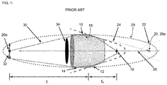
- FIG. 1 schematically illustrates an axially symmetric Wolter Type I optic configured for two-dimensional (2D) imaging and comprising a confocal hyperboloidal mirror section followed by an ellipsoidal mirror section.
- FIG. 2 schematically illustrates an example polycapillary x-ray optic.
- FIG. 3A includes various equations relevant to a hyperbolic surface portion (e.g., in 2D) and a hyperboloidal surface portion (e.g., in 3D) in accordance with certain implementations described herein.
- a hyperbolic surface portion e.g., in 2D
- a hyperboloidal surface portion e.g., in 3D
- FIG. 3B schematically illustrates an example x-ray optic having hyperbolic/hyperboloidal surface portions in the x-y plane in accordance with certain implementations described herein.
- FIG. 4 schematically illustrates a cross-sectional view of an example x-ray optic comprising at least one first mirror section having a hyperboloidal surface shape and at least one second mirror section having a paraboloidal surface shape in accordance with certain implementations described herein.
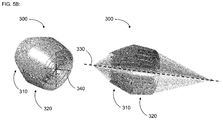
- FIG. 5A schematically illustrates a perspective view and a one-half cut-away view of an example cylindrical x-ray optic in accordance with certain implementations described herein.
- FIG. 5B schematically illustrates a perspective view and a one-quarter cut-away view of an example rotational symmetric x-ray optic in accordance with certain implementations described herein.
- FIG. 6A schematically illustrates first and second substrates in accordance with certain implementations described herein.
- FIG. 6B schematically illustrates a pair of first substrates and a pair of second substrates in accordance with certain implementations described herein.
- X-ray mirrors can be used to focus or collimate x-rays from an x-ray source or from a sample irradiated by ionizing radiation (e.g., x-rays; electrons; ions), and to produce an image of an object irradiated by an x-ray beam (e.g., in an x-ray microscope).
- ionizing radiation e.g., x-rays; electrons; ions
- Conventional x-ray mirror optics are limited in numerical aperture, optical aperture, and/or focal length, and these limitations can be problematic for various applications.
- Examples of conventional x-ray mirror optics to be used with an x-ray source include x-ray mirror lenses having a Wolter-type x-ray optic configuration.
- a Wolter-type x-ray optic configuration is a compound optic configuration comprising two mirrors of different reflecting surface profiles, and such configurations have been used previously for x-ray telescopes.
- FIG. 1 schematically illustrates an axially symmetric Wolter Type I optic 10 configured for two-dimensional (2D) imaging and comprising a confocal hyperboloidal mirror section 12 followed by (e.g., upstream from) an ellipsoidal mirror section 14 .
- At least some of the radiation (e.g., neutrons; x-rays) emitted from a source positioned substantially at a focus 16 of the hyperboloidal mirror section 12 is reflected by the hyperboloidal mirror section 12 and is subsequently reflected by the ellipsoidal mirror section 14 .
- the radiation 18 reflected from the hyperboloidal mirror section 12 appears to come from a conjugate focus 20 of a virtual hyperbola 22 corresponding to the hyperboloidal mirror section 12 (denoted in FIG.
- M magnification
- Other configurations in which the positions of the object and the image are switched with one another (e.g., resulting in a demagnification of the object) are also possible.
- other configurations which utilize a confocal hyperbolic mirror section followed by (e.g., upstream from) an elliptic mirror section can be used for one-dimensional (1D) imaging.
- an aperture stop 34 can be configured (e.g., positioned along the optical axis 36 of the Wolter optic 10 ) to absorb x-rays that are not reflected by the Wolter optic 10 . While FIG. 1 shows a single Wolter optic 10 , nesting of many mirrors can increase flux collection.
- FIG. 2 schematically illustrates an example polycapillary x-ray optic 50 , which is considered to be a non-imaging optic.
- Each capillary of the polycapillary x-ray optic 50 serves as a light-guide, with the x-rays 52 from an x-ray source 54 received by a first end 56 a of the polycapillary x-ray optic 50 being reflected many times on the inside surface of the hollow capillaries.
- the points on the capillary surfaces where an incident x-ray is reflected are not deterministic. As seen in FIG.
- x-rays 58 emerging from the second end 56 b of the polycapillary x-ray optic 50 diverge, with an angular extent that is determined by the critical angle of the capillary surfaces (e.g., in a x-ray spot having a micron-scale width). Since the critical angle is proportional to the wavelength, soft x-rays spread rapidly beyond the second end 56 b of the polycapillary x-ray optic 50 , while hard x-rays generally retain their directionality. However, the critical angle also determines the acceptance at the first end 56 a of the polycapillary x-ray optic, 50 with the acceptance much higher for soft x-rays than for hard x-rays.
- NA numerical apertures
- an axially symmetric single-reflection x-ray optic (e.g., ellipsoidal x-ray optic) has an NA that is generally limited to about the critical angle.
- Axially symmetric Wolter optics which provide two reflections for collimating optics (see, e.g., FIG. 1 ) and four reflections for a focusing double Wolter optic can be configured to improve the radiation collection greatly (e.g., four times the critical angle for a focusing Wolter optic, in which two mirrored Wolter optics are used).
- the NA is increased further by increasing the number of reflections from the x-ray optic.
- a beam stop e.g., aperture stop 34
- These unreflected x-rays propagating through the central region can be a substantial fraction of the emitted x-rays and these x-rays are lost (e.g., not used in the focusing, collimating, and/or imaging by the x-ray optic), even for x-ray optics having a large diameter.
- nested x-ray optics e.g., multiple x-ray optic components arranged concentrically about a common optical axis
- axially symmetric nested x-ray optics can be very difficult to make using conventional technology (e.g., glass capillary shaping through mandrels or by glass blowing)
- certain implementations described herein can utilize KB-type arrangements of sets of one-dimensional x-ray optic elements (e.g., sets of x-ray mirrors that are substantially curved in one plane along the optical axis and substantially flat in another plane substantially perpendicular to the optical axis).
- the limited NA can be problematic in applications in which these conventional x-ray mirror optics are used.
- the x-ray mirror optic can limit the x-rays collected from a laboratory x-ray source (e.g., which can have a brightness that is orders of magnitude lower than that of a synchrotron x-ray source) and directed to illuminate a sample.
- the x-ray mirror optic can limit the x-rays collected for analysis (e.g., by an energy dispersive detector, wavelength spectrometer, and/or confocal XRF analyzer) from a sample irradiated by ionizing radiation (e.g., x-rays; electrons; protons), the x-rays generated in response to (e.g., induced by) the ionizing radiation.
- ionizing radiation e.g., x-rays; electrons; protons
- the x-ray mirror optic can limit the spatial resolution and/or the x-ray collection efficiency when used as either a condenser or an objective lens in a full-field x-ray imaging microscope.
- the focal length of conventional x-ray mirror optics can also be limited.
- the focal length can be constrained to be longer than either the length of the x-ray mirror optic (e.g., for a single x-ray mirror optic) or the length of the downstream x-ray mirror optic (e.g., for two or more x-ray mirror optics, such as Wolter type I x-ray mirror optics, twin paraboloidal mirror lenses, and/or KB mirror pairs).
- the long focal length can lead directly to long distances between the sample and the detector (e.g., camera) (e.g., when used as an objective in a full-field x-ray transmission microscope or as an focusing optic in a confocal x-ray fluorescence system). These long distances, resulting from the long focal lengths, can become problematic for practical reasons when fabricating x-ray analysis systems (e.g., less stable performance in response to thermal fluctuations and/or utilizing excessive laboratory space).
- an x-ray mirror optic having a plurality of surface segments with quadric (e.g., hyperbolic or hyperboloidal) cross-sections having differing quadric (e.g., hyperbolic or hyperboloidal) parameters.
- the quadric (e.g., hyperbolic or hyperboloidal) cross-sections of the surface segments share a common axis, and are configured to reflect x-rays in a plurality of reflections along a single direction or in a scattering plane (e.g., defined as containing the incident x-ray on the surface and the reflected x-ray from the surface).
- Certain such implementations advantageously provide larger numerical apertures, larger optical apertures, and/or shorter focal lengths than do conventional x-ray mirror optics. Certain implementations can be used in place of conventional x-ray optics (e.g., condensers; KB mirror pairs) and/or can be used in place of a zone plate x-ray optic.
- conventional x-ray optics e.g., condensers; KB mirror pairs
- While various implementations are described herein as comprising reflective surface portions that are curved in two dimensions (e.g., paraboloidal; ellipsoidal; hyperboloidal)(e.g., having a first curved cross-section in a first plane and having a second curved cross-section in a second plane perpendicular to the first plane), other implementations can comprise reflective surface portions that are curved in only one direction (e.g., parabolic; elliptic; hyperbolic) (e.g., having a first curved cross-section in a first plane and having a second substantially flat cross-section in a second plane perpendicular to the first plane).
- Certain implementations described herein provide axially symmetric “Super Wolter” x-ray optics comprising three or more x-ray mirror sections having quadric surface profiles (e.g., parabolic; elliptic; hyperbolic; paraboloidal; ellipsoidal; hyperboloidal).
- these three or more x-ray mirror sections are produced from replicas of one or more mandrels.
- the surfaces of multiple mandrels can be individually shaped to have the quadric surface profiles of the axially symmetric mirror sections and aligned with one another.
- mandrels can be used to fabricate the sets of x-ray mirror sections (e.g., x-ray mirror sections substantially curved in one dimension or two dimensions) in multiple parts (e.g., two halves; two or more parts) and the sets of x-ray mirror sections can be assembled together to cover a predetermined range of angles around the optical axis (e.g., at least 60 degrees; at least 90 degrees; at least 180 degrees; at least 270 degrees; up to 360 degrees; less than 360 degrees).
- a predetermined range of angles around the optical axis e.g., at least 60 degrees; at least 90 degrees; at least 180 degrees; at least 270 degrees; up to 360 degrees; less than 360 degrees.
- portions of an inner surface of a continuous glass tube can be directly shaped to form the quadric surface profiles of the axially symmetric mirror sections.
- portions of the shaped axially symmetric capillaries are cut and aligned (e.g., by a holder or by adhering the portions together) to form the x-ray optic.
- the inner surfaces of the glass capillary portions can comprise at least one layer (e.g., at least one coating; a plurality of layers; multilayers) comprising at least one high atomic number element (e.g., platinum; iridium), the at least one layer configured to improve the x-ray reflectivity of the inner surfaces of the glass capillary portions (e.g., in a predetermined range of x-ray energies).
- at least one layer e.g., at least one coating; a plurality of layers; multilayers
- at least one high atomic number element e.g., platinum; iridium
- FIG. 3A includes various equations relevant to a hyperbolic surface portion (e.g., in 2D) and a hyperboloidal surface portion (e.g., in 3D) in accordance with certain implementations described herein.
- FIG. 3B schematically illustrates an example x-ray optic 100 having hyperbolic/hyperboloidal surface portions 110 , 120 in the x-y plane in accordance with certain implementations described herein.
- a first hyperbolic/hyperboloidal surface portion 110 has one of its foci 112 a aligned with a small target region 130 of an x-ray source which generates x-rays, the first hyperbolic/hyperboloidal surface portion 110 configured to create a reflected x-ray beam that appears to originate from, and to be diverging from, the conjugate focus 112 b of the first hyperbolic/hyperboloidal surface portion 110 . While the discussion herein is valid for both hyperbolic mirrors in 2D and hyperboloidal mirrors in 3D, only hyperboloidal mirror optics are referred to explicitly for simplicity sake.
- an x-ray source 130 is positioned at a first focus (C, 0) (e.g., a primary focus 112 a ) of a first hyperboloidal surface portion 110 of a first hyperboloidal x-ray mirror 114 , the first hyperboloidal surface portion 110 having a first hyperboloidal shape that is symmetric about the y-axis.
- At least some of the x-rays 140 emitted from the x-ray source are reflected by the first hyperboloidal surface portion 110 (e.g., at a position (x, y)), and the reflected x-rays 142 appear to originate from a second focus ( ⁇ C, 0) (e.g., the conjugate focus 112 b ) of the first hyperboloidal surface portion 110 .
- a second focus ⁇ C, 0
- the grazing angle ⁇ grazing (e.g., the angle between the emitted x-ray 140 and the tangent of the first hyperboloidal surface portion 110 at the reflection point (x, y)) increases.
- the first hyperboloidal surface portion 110 no longer reflects the x-rays 140 from the x-ray source 130 .
- the angle between the reflected x-ray 142 and the first axis is equal to ( ⁇ 2 ⁇ grazing ).
- FIG. 4 schematically illustrates a cross-sectional view of an example x-ray optic 200 comprising at least one first mirror section 210 having a hyperboloidal surface shape and at least one second mirror section 220 having a paraboloidal surface shape in accordance with certain implementations described herein.
- the at least one first mirror section 210 can comprise a unitary axially symmetric mirror section and the at least one second mirror section 220 can comprise a unitary axially symmetric mirror section.
- these unitary axially symmetric mirror sections are portions of a single monolithic reflecting element (e.g., surface of an axially symmetric substrate or tube).
- the focus 222 of the paraboloidal surface shape is at (e.g., substantially coincident with) the conjugate focus 212 b of the hyperboloidal surface shape.
- the at least one second mirror section 220 can collimate the x-rays that are emitted by the x-ray source and that are reflected by the at least one first mirror section 210 , which appear to be emitted from a virtual x-ray source positioned at the conjugate focus 212 b of the hyperboloidal surface shape.
- the incident x-rays are collimated and incident from the right-side of FIG.
- the example x-ray optic 200 focuses the x-rays reflected by the at least one first mirror section 210 and the at least one second mirror section 220 to the primary focus of the hyperboloidal surface shape (e.g., acts as a telescope).
- the focus of the paraboloidal surface shape can be at (e.g., substantially coincident with) the conjugate focus 212 b of the last hyperboloidal surface shape of the plurality of hyperboloidal surface shapes. While not shown in FIG.
- certain implementations comprise one or more beam stops configured to intercept (e.g., block) unreflected x-rays emitted from the x-ray source from propagating downstream through the central region of the axially symmetric x-ray optic.
- FIG. 5A schematically illustrates a perspective view and a one-half cut-away view of an example cylindrical Wolter x-ray optic 300 in accordance with certain implementations described herein.
- FIG. 5B schematically illustrates a perspective view and a one-quarter cut-away view of an example rotational symmetric Wolter x-ray optic 300 in accordance with certain implementations described herein.
- 5A and 5B comprises a first plurality of non-axially symmetric mirror sections 310 (e.g., two, three, four, five or more) each having a quadric (e.g., hyperbolic) surface shape and a second plurality of non-axially symmetric mirror sections 320 (e.g., two, three, four, five or more) each having a quadric (e.g., hyperbolic) surface shape.
- a first plurality of non-axially symmetric mirror sections 310 e.g., two, three, four, five or more
- a quadric e.g., hyperbolic
- the mirror sections 310 are curved in only one first plane (e.g., along an optical axis 330 of the x-ray optic 300 ) and the mirror sections 320 are curved in only one second plane (e.g., along the optical axis 330 of the x-ray optic 300 and substantially perpendicular to the first plane) in accordance with certain implementations described herein.
- the mirror sections 310 are axially symmetric (e.g., curved around the optical axis 330 of the x-ray optic 300 ) and the mirror sections 320 are axially symmetric (e.g., curved around the optical axis 330 of the x-ray optic 300 ) in accordance with certain implementations described herein.
- the first plurality of mirror sections 310 and/or the second plurality of mirror sections 320 can comprise pairs of mirror sections, each pair comprising two mirror sections that have substantially the same quadric (e.g., hyperbolic) surface shape and substantially the same quadric surface parameters as one another and are on opposite sides of the optical axis 330 of the x-ray optic 300 .
- the first plurality of mirror sections 310 and/or the second plurality of mirror sections 320 can comprise multiple mirror sections that have substantially the same quadric (e.g., hyperbolic) surface shape and substantially the same quadric surface parameters as one another and are positioned around the optical axis 330 of the x-ray optic 300 .
- the first plurality of mirror sections 310 can provide focusing (e.g., one-dimensional) along a first direction (e.g., line), and the second plurality of mirror sections 320 can provide focusing (e.g., one-dimensional) along a second direction (e.g., line) substantially perpendicular to the first direction, resulting in two-dimensional focusing (e.g., point focusing), in a manner similar to that of Kirkpatrick-Baez (KB) x-ray optics.
- a first direction e.g., line
- a second direction e.g., line
- the first plurality of mirror sections 310 can be nested (e.g., spaced apart from and extending generally along one another; arranged concentrically about a common optical axis; substantially parallel with one another) and/or the second plurality of mirror sections 320 can be nested (e.g., spaced apart from and extending generally along one another; arranged concentrically about a common optical axis; substantially parallel with one another) and can be oriented substantially perpendicularly to the first plurality of mirror sections (e.g., similar to a KB mirror configuration).
- adjacent mirror sections of the first plurality of mirror sections are spaced from one another by a distance in a range 1 micron to 10 microns.
- adjacent mirror sections of the second plurality are spaced from one another by a distance in a range of 1 micron to 10 microns.
- the first plurality of mirror sections 310 and the second plurality of mirror sections 320 are interweaved with one another (e.g., the mirrors sections 310 , 320 of the first plurality and the second plurality alternate with one another along an optical axis 330 of the x-ray optic 300 .
- the x-ray optic 300 comprises a plurality of nested mirror portions 310 , 320 and a support structure 340 (e.g., spacers; struts; braces) configured to support and align the mirror portions 310 , 320 relative to one another.
- a support structure 340 e.g., spacers; struts; braces
- the mirror sections 310 , 320 of the first plurality and/or the second plurality can be etched into a substrate (e.g., silicon) (e.g., using metal assisted etching or LIGA).
- FIG. 6A schematically illustrates first and second substrates 410 , 420 in accordance with certain implementations described herein.
- the first substrate 410 comprises a first plurality of reflective surfaces 412 (e.g., etched into the first substrate 410 ) that are curved in a first cross-sectional plane 414 (schematically illustrated by a dotted line) and that are substantially not curved (e.g., straight) along a direction substantially perpendicular to the first cross-sectional plane 414 .
- the second substrate 420 comprises a second plurality of reflective surfaces 422 (e.g., etched into the second substrate 420 ) that are curved in a second cross-sectional plane 424 (schematically illustrated by a dotted line) and that are substantially not curved (e.g., straight) along a direction substantially perpendicular to the second cross-sectional plane 424 .
- the second substrate 420 is positioned relative to the first substrate 410 such that the second cross-sectional plane 424 is substantially perpendicular to the first cross-sectional plane 414 .
- the first plurality of reflective surfaces 412 and the second plurality of reflective surfaces 422 are configured to focus incident x-rays to a focal point (e.g., in a KB mirror configuration).
- the first plurality of reflective surfaces 412 and the second plurality of reflective surfaces 422 are configured to collimate incident x-rays (e.g., collimate in two dimensions). In certain implementations, the first plurality of reflective surfaces 412 and the second plurality of reflective surfaces 422 are separated from one another by a distance in a range of less than one micron, a range of 1 micron to 5 microns, a range of 5 microns to 20 microns, or a range of 20 microns to 100 microns.
- the reflective surfaces 412 , 422 are KB-mirror-like to focus in a point-like manner, while in certain other implementations, the reflective surfaces 412 , 422 both have a collimating shape to collimate in two dimensions.
- FIG. 6B schematically illustrates a pair of first substrates 410 and a pair of second substrates 420 in accordance with certain implementations described herein.
- One substrate of the pair of first substrates 410 comprises a first plurality of reflective surfaces 412 a (e.g., etched into the substrate) that are curved in a first cross-sectional plane 414 a and that are substantially not curved (e.g., straight) along a direction substantially perpendicular to the first cross-sectional plane 414 a and the other substrate of the pair of first substrates 410 comprises a second plurality of reflective surfaces 412 b (e.g., etched into the substrate) that are curved in a second cross-sectional plane 414 b and that are substantially not curved (e.g., straight) along a direction substantially perpendicular to the second cross-sectional plane 414 b .
- first plurality of reflective surfaces 412 a e.g., etched into the substrate
- One substrate of the pair of second substrates 420 comprises a third plurality of reflective surfaces (not shown)(e.g., etched into the substrate) that are curved in a third cross-sectional plane 424 a and that are substantially not curved (e.g., straight) along a direction substantially perpendicular to the third cross-sectional plane 424 a and the other substrate of the pair of second substrates 420 comprises a fourth plurality of reflective surfaces (not shown)(e.g., etched into the substrate) that are curved in a fourth cross-sectional plane 424 b and that are substantially not curved (e.g., straight) along a direction substantially perpendicular to the fourth cross-sectional plane 424 b .
- the pair of first substrates 410 can be positioned such that the second cross-sectional plane 414 b is substantially parallel to the first cross-sectional plane 414 a
- the pair of second substrates 420 can be positioned such that the fourth cross-sectional plane 424 b is substantially parallel to the third cross-sectional plane 424 a
- the third cross-sectional plane 424 a is substantially perpendicular to the first cross-sectional plane 414 a
- the pair of first substrates 410 can form a Wolter x-ray optic and the pair of second substrates 420 can form a Wolter x-ray optic in an orthogonal direction to that of the pair of first substrates 410 .
- the separation between adjacent and substantially parallel reflective surfaces of a plurality of reflective surfaces can be on the order of microns (e.g., in a range of 1 micron to 10 microns), and the surface roughness can be less than 2 nanometers (e.g., by using thermal annealing or another process to reduce surface roughness of the etched surfaces).
- the example x-ray optic can be used in place of a zone plate x-ray optic downstream from a sample under analysis.
- the example x-ray optic can provide achromatic focusing, so that multiple zone plates for different x-ray wavelengths are not needed.
- a single x-ray optic in accordance with certain implementations described herein can be used if the x-ray wavelengths are sufficiently close together such that the critical angles for reflection are not substantially different from one another.
- the x-ray optic can be used as a zone plate replacement for hard x-ray energy imaging (e.g., 17 keV with molybdenum x-rays or 11 keV with Au x-rays).
- zone plates exhibit substantial chromatic aberration, so that laboratory x-ray systems are limited to x-ray sources that produce a characteristic x-ray line that can be separated from other characteristic x-ray lines (e.g., the K ⁇ x-ray line can be filtered from the K ⁇ x-ray line).
- other laboratory x-ray sources e.g., molybdenum; silver; rhodium K-line
- one or more x-ray mirrors having a plurality of hyperbolic/hyperboloidal surface portions can be used to collect x-rays from an x-ray source with a large emission angle.
- the one or more x-ray mirrors comprises a first hyperboloidal surface portion 110 , as described above, and a second hyperboloidal surface portion 120 that has a second axis common (e.g., shared; substantially coaxial) with the first axis (e.g., the x-axis) but having a smaller value of the asymptote slope b/a, and with a first focus (e.g., a primary focus 122 a ) substantially coincident with the conjugate focus 112 b at ( ⁇ c, 0) of the first hyperboloidal surface portion 110 .
- a first focus e.g., a primary focus 122 a
- the first hyperboloidal surface portion 110 is configured to intercept (e.g., reflect) x-rays 140 emitted from the x-ray source 130 at the primary focus 112 a at (c, 0) of the first hyperboloidal surface portion 110 . These singly-reflected x-rays 142 appear to originate from the conjugate focus 112 b at ( ⁇ c, 0) of the first hyperboloidal surface portion 110 (e.g., a virtual x-ray source).
- the second hyperboloidal surface portion 120 is configured to intercept (e.g., reflect) x-rays 142 reflected by the first hyperboloidal surface portion 110 , resulting in an additional reduction of the angle between the twice-reflected x-rays 144 with the shared hyperboloidal mirror axis (e.g., the x-axis).
- the twice-reflected x-rays 144 appear to originate from a second focus 122 b at ( ⁇ Cl, 0) (e.g., the conjugate focus 122 b ) of the second hyperboloidal surface portion 120 .
- additional hyperboloidal surface portions can be used (e.g., 3, 4, 5, or more hyperboloidal surface portions), with each hyperboloidal surface portion serving as a virtual x-ray source for the subsequent hyperboloidal surface portion.
- the sequential hyperboloidal surface portions have successively smaller asymptote slope values b/a, to multiply reflect and to obtain larger reductions of the angle between the initial x-ray emitted from the x-ray source with the hyperboloidal mirror axis common to (e.g., shared by; substantially coaxial with) all the hyperboloidal mirror portions (e.g., the x-axis). For example, the angle between the last reflected x-ray and the shared hyperboloidal mirror axis can be reduced to be close to zero.
- an x-ray optic comprises a plurality of hyperboloidal mirror surface portions that are configured to collect x-rays from an x-ray source with large angles with respect to the shared hyperboloidal axis (e.g., up to 2 ⁇ N ⁇ critical , where N is the number of successive hyperboloidal surface portions.
- the x-rays emitted from the x-ray source at (C, 0) that impinge and are not reflected by the first hyperboloidal surface are intercepted by a central beam stop and/or the nested set of additional hyperboloidal surfaces.
- incident x-rays are reflected by and focused by the hyperbolic/hyperboloidal surface portions disclosed in the example implementation #1 to converge at the point (C, 0).
- Certain such implementations utilize a carefully tailored converging beam of x-rays to match the reversed output from example implementations #1.
- one or more x-ray mirrors having a plurality of nested hyperbolic/hyperboloidal surface portions can be used to collect x-rays in a large collection angle from the x-ray source.
- a nested array of hyperboloidal mirrors having a common (e.g., shared; substantially coincident) primary focus and a common (e.g., shared; substantially coaxial) hyperboloidal axis each hyperboloidal mirror of the nested array having a different value of the hyperbolic parameter b (or a different value of the ratio b/a, since the nested set shares the same value of c, so if b changes, b/a also changes).
- the thickness of the hyperboloidal mirror is less than the gap distance between two neighboring hyperboloidal mirrors.
- one or more x-ray mirrors having a plurality of nested hyperbolic/hyperboloidal surface portions can be used in combination with a nested set of parabolic/paraboloidal mirror surfaces to produce a collimated x-ray beam.
- the nested set of parabolic/paraboloidal mirror surfaces can be substantially coaxial with the common (e.g., shared) hyperbolic/hyperboloidal axis and the foci of the parabolic/paraboloidal mirror surfaces can be at the conjugate foci of the last hyperbolic/hyperboloidal mirror surfaces of the nested hyperbolic/hyperboloidal mirror surfaces (e.g., provided that the angle of the x-rays reflected by the last hyperbolic/hyperboloidal mirror surface and the shared axis is less than the critical angle of the parabolic/paraboloidal mirror surface).
- the common e.g., shared
- the foci of the parabolic/paraboloidal mirror surfaces can be at the conjugate foci of the last hyperbolic/hyperboloidal mirror surfaces of the nested hyperbolic/hyperboloidal mirror surfaces (e.g., provided that the angle of the x-rays reflected by the last hyperbolic/hyperboloidal mirror surface and the shared axis is less than the
- one or more x-ray mirrors having a plurality of hyperbolic/hyperboloidal surface portions can be used in combination with an optic train following the plurality of hyperbolic/hyperboloidal surface portions, to produce a focused x-ray beam.
- the optic train can comprise at least one of the following:
- the x-ray optic is a compound optic and comprises a first plurality of orthogonal 1D focusing optics comprising hyperbolic surface portions and corresponding elliptical surface portions following the hyperbolic surface portions and a second plurality of orthogonal 1D focusing optics comprising hyperbolic surface portions and corresponding elliptical surface portions following the hyperbolic surface portions, configured to provide point focusing.
- the first plurality can be nested with one another and/or the second plurality can be nested with one another.
- the x-ray optic can be a compound optic configured to collect x-rays from a point source over a large acceptance angle.
- the x-ray optic is a compound optic and comprises a first plurality of orthogonal 1D focusing optics comprising hyperbolic surface portions and corresponding parabolic surface portions following the hyperbolic surface portions (e.g., configured to provide 1D collimation) and a second plurality of orthogonal 1D focusing optics comprising hyperbolic surface portions and corresponding parabolic surface portions following the hyperbolic surface portions (e.g., configured to provide 1D collimation), all configured to provide 2D collimation.
- the first plurality can be nested with one another and/or the second plurality can be nested with one another.
- the x-ray optic can be a compound optic configured to focus a collimated x-ray beam to a point focus.
- the x-ray optic of example implementation #6 can be followed by another x-ray optic of example implementation #6 in reverse order, so as to collect x-rays from an x-ray source and to focus the x-rays to a point focus.
- the x-ray optic of example implementation #7 can be followed by another x-ray optic of example implementation #7 in reverse order, so as to collect collimated x-rays and to focus the x-rays to a point focus.
- the terms “generally parallel” and “substantially parallel” refer to a value, amount, or characteristic that departs from exactly parallel by ⁇ 10 degrees, by ⁇ 5 degrees, by ⁇ 2 degrees, by ⁇ 1 degree, or by ⁇ 0.1 degree
- the terms “generally perpendicular” and “substantially perpendicular” refer to a value, amount, or characteristic that departs from exactly perpendicular by ⁇ 10 degrees, by ⁇ 5 degrees, by ⁇ 2 degrees, by ⁇ 1 degree, or by ⁇ 0.1 degree.
- the ranges disclosed herein also encompass any and all overlap, sub-ranges, and combinations thereof. Language such as “up to,” “at least,” “greater than,” less than,” “between,” and the like includes the number recited.
Landscapes
- Physics & Mathematics (AREA)
- Chemical & Material Sciences (AREA)
- Health & Medical Sciences (AREA)
- High Energy & Nuclear Physics (AREA)
- Spectroscopy & Molecular Physics (AREA)
- Engineering & Computer Science (AREA)
- General Engineering & Computer Science (AREA)
- Biochemistry (AREA)
- Life Sciences & Earth Sciences (AREA)
- Analytical Chemistry (AREA)
- General Health & Medical Sciences (AREA)
- General Physics & Mathematics (AREA)
- Immunology (AREA)
- Pathology (AREA)
- Crystallography & Structural Chemistry (AREA)
- Toxicology (AREA)
- Lenses (AREA)
- Analysing Materials By The Use Of Radiation (AREA)
- Optical Elements Other Than Lenses (AREA)
Abstract
Description
-
- Type I: Comprising an ellipsoidal mirror section and a hyperboloidal mirror section with x-rays reflected in the same direction (e.g., for demagnifying use);
- Type II: Comprising a hyperboloidal mirror section and an ellipsoidal mirror section, with x-rays reflected in opposite directions; and
- Type III: Comprising an ellipsoidal mirror section and a paraboloidal mirror section, with x-rays reflected in opposite directions.
-
- An elliptical/ellipsoidal mirror surface (elliptical if following a hyperbolic mirror surface, ellipsoidal if following a hyperboloidal mirror surface), when the x-ray beam divergence angle is less than the critical angle of the reflection surface of the elliptical/ellipsoidal mirror surface;
- A first parabolic/paraboloidal mirror surface (parabolic if following a hyperbolic mirror surface, paraboloidal if following a hyperboloidal mirror surface) configured to collect and collimate the x-rays followed by a second parabolic/paraboloidal mirror surface configured to focus the collimated beam;
- An elliptical/ellipsoidal mirror surface (elliptical if following a hyperbolic mirror surface, ellipsoidal if following a hyperboloidal mirror surface) followed by a second set of hyperbolic/hyperboloidal surface portions having a reversed orientation relative to the first set of hyperbolic/hyperboloidal surface portions; and
- A cylindrical mirror, when the x-ray beam divergence angle, after the plurality of hyperbolic/hyperboloidal surface portions, is smaller than the critical angle of the cylindrical mirror. Certain such implementations provide a symmetric focusing system with 1:1 magnification when the second set of hyperbolic/hyperboloidal surface portions is the same as the first set of hyperbolic/hyperboloidal surface portions.
Claims (18)
Priority Applications (1)
| Application Number | Priority Date | Filing Date | Title |
|---|---|---|---|
| US17/169,159 US11217357B2 (en) | 2020-02-10 | 2021-02-05 | X-ray mirror optics with multiple hyperboloidal/hyperbolic surface profiles |
Applications Claiming Priority (2)
| Application Number | Priority Date | Filing Date | Title |
|---|---|---|---|
| US202062972236P | 2020-02-10 | 2020-02-10 | |
| US17/169,159 US11217357B2 (en) | 2020-02-10 | 2021-02-05 | X-ray mirror optics with multiple hyperboloidal/hyperbolic surface profiles |
Publications (2)
| Publication Number | Publication Date |
|---|---|
| US20210247334A1 US20210247334A1 (en) | 2021-08-12 |
| US11217357B2 true US11217357B2 (en) | 2022-01-04 |
Family
ID=77176983
Family Applications (1)
| Application Number | Title | Priority Date | Filing Date |
|---|---|---|---|
| US17/169,159 Active US11217357B2 (en) | 2020-02-10 | 2021-02-05 | X-ray mirror optics with multiple hyperboloidal/hyperbolic surface profiles |
Country Status (2)
| Country | Link |
|---|---|
| US (1) | US11217357B2 (en) |
| WO (1) | WO2021162947A1 (en) |
Cited By (2)
| Publication number | Priority date | Publication date | Assignee | Title |
|---|---|---|---|---|
| US20220128487A1 (en) * | 2020-10-23 | 2022-04-28 | Rigaku Corporation | Imaging type x-ray microscope |
| US20220357290A1 (en) * | 2019-06-24 | 2022-11-10 | Sms Group Gmbh | Controlling the process parameters by means of radiographic online determination of material properties when producing metallic strips and sheets |
Citations (135)
| Publication number | Priority date | Publication date | Assignee | Title |
|---|---|---|---|---|
| US4426718A (en) | 1980-09-01 | 1984-01-17 | Hitachi, Ltd. | X-Ray diffraction apparatus |
| US4562583A (en) * | 1984-01-17 | 1985-12-31 | The United States Of America As Represented By The Administrator Of The National Aeronautics And Space Administration | Spectral slicing X-ray telescope with variable magnification |
| US4798446A (en) | 1987-09-14 | 1989-01-17 | The United States Of America As Represented By The United States Department Of Energy | Aplanatic and quasi-aplanatic diffraction gratings |
| US4807268A (en) | 1983-11-04 | 1989-02-21 | University Of Southern California | Scanning monochrometer crystal and method of formation |
| US4940319A (en) | 1988-04-28 | 1990-07-10 | Kabushiki Kaisha Toshiba | X-ray mirror apparatus and method of manufacturing the same |
| US4951304A (en) | 1989-07-12 | 1990-08-21 | Adelphi Technology Inc. | Focused X-ray source |
| US5001737A (en) | 1988-10-24 | 1991-03-19 | Aaron Lewis | Focusing and guiding X-rays with tapered capillaries |
| US5276724A (en) | 1991-09-20 | 1994-01-04 | Fujitsu Limited | X-ray exposure apparatus |
| US5452142A (en) | 1992-10-20 | 1995-09-19 | Hughes Aircraft Company | Approach for positioning, fabricating, aligning and testing grazing, convex, hyperbolic mirrors |
| US5461657A (en) | 1993-06-30 | 1995-10-24 | Canon Kabushiki Kaisha | X-ray mirror, and x-ray exposure apparatus and device manufacturing method employing the same |
| US5604782A (en) | 1994-05-11 | 1997-02-18 | The Regents Of The University Of Colorado | Spherical mirror grazing incidence x-ray optics |
| US5682415A (en) | 1995-10-13 | 1997-10-28 | O'hara; David B. | Collimator for x-ray spectroscopy |
| US5715291A (en) | 1996-01-10 | 1998-02-03 | Hitachi, Ltd. | Phase-contrast X-ray CT apparatus |
| US5772903A (en) | 1996-09-27 | 1998-06-30 | Hirsch; Gregory | Tapered capillary optics |
| US5799056A (en) | 1994-08-01 | 1998-08-25 | Ovonic Synthetic Materials Company, Inc. | Optical element of multilayered thin film for x-rays and neutrons |
| US5881126A (en) | 1996-03-29 | 1999-03-09 | Hitachi, Ltd. | Phase contrast X ray imaging system |
| US6108397A (en) | 1997-11-24 | 2000-08-22 | Focused X-Rays, Llc | Collimator for x-ray proximity lithography |
| US6278764B1 (en) | 1999-07-22 | 2001-08-21 | The Regents Of The Unviersity Of California | High efficiency replicated x-ray optics and fabrication method |
| EP1169713A2 (en) | 1999-04-09 | 2002-01-09 | Osmic, Inc. | X-ray lens system |
| US6359964B1 (en) | 1998-11-25 | 2002-03-19 | U.S. Philips Corporation | X-ray analysis apparatus including a parabolic X-ray mirror and a crystal monochromator |
| US20020080916A1 (en) | 1999-08-02 | 2002-06-27 | Licai Jiang | Multilayer optics with adjustable working wavelength |
| US6442231B1 (en) | 1997-08-15 | 2002-08-27 | O'hara David B. | Apparatus and method for improved energy dispersive X-ray spectrometer |
| US6504902B2 (en) | 2000-04-10 | 2003-01-07 | Rigaku Corporation | X-ray optical device and multilayer mirror for small angle scattering system |
| US6504901B1 (en) | 1998-07-23 | 2003-01-07 | Bede Scientific Instruments Limited | X-ray focusing apparatus |
| US20030054133A1 (en) | 2000-08-07 | 2003-03-20 | Wadley Hadyn N.G. | Apparatus and method for intra-layer modulation of the material deposition and assist beam and the multilayer structure produced therefrom |
| JP2003149392A (en) | 2001-11-09 | 2003-05-21 | Tohken Co Ltd | X-ray intensifying reflecting plate and x-ray inspection device |
| US20030112923A1 (en) | 2001-12-18 | 2003-06-19 | Bruker Axs Gmbh | X-ray optical system with collimator in the focus of an X-ray mirror |
| US6815363B2 (en) | 2000-08-11 | 2004-11-09 | The Regents Of The University Of California | Method for nanomachining high aspect ratio structures |
| US6829327B1 (en) | 2000-09-22 | 2004-12-07 | X-Ray Optical Systems, Inc. | Total-reflection x-ray fluorescence apparatus and method using a doubly-curved optic |
| US20050025281A1 (en) | 2003-06-13 | 2005-02-03 | Boris Verman | Beam conditioning system |
| US6885503B2 (en) | 2001-11-09 | 2005-04-26 | Xradia, Inc. | Achromatic fresnel optics based lithography for short wavelength electromagnetic radiations |
| US6914723B2 (en) | 2001-11-09 | 2005-07-05 | Xradia, Inc. | Reflective lithography mask inspection tool based on achromatic Fresnel optics |
| US6934359B2 (en) | 2001-06-19 | 2005-08-23 | X-Ray Optical Systems, Inc. | Wavelength dispersive XRF system using focusing optic for excitation and a focusing monochromator for collection |
| US6949748B2 (en) * | 2002-04-16 | 2005-09-27 | The Regents Of The University Of California | Biomedical nuclear and X-ray imager using high-energy grazing incidence mirrors |
| US7057187B1 (en) | 2003-11-07 | 2006-06-06 | Xradia, Inc. | Scintillator optical system and method of manufacture |
| US7110503B1 (en) | 2000-08-07 | 2006-09-19 | Muradin Abubekirovich Kumakhov | X-ray measuring and testing system |
| US7119953B2 (en) | 2002-12-27 | 2006-10-10 | Xradia, Inc. | Phase contrast microscope for short wavelength radiation and imaging method |
| US20060239405A1 (en) | 2003-06-13 | 2006-10-26 | Osmic, Inc. | Beam conditioning system with sequential optic |
| US7149283B2 (en) | 2002-09-06 | 2006-12-12 | Siemens Aktiengesellschaft | Method for producing and applying an antiscatter grid or collimator to an x-ray or gamma detector |
| US7170969B1 (en) | 2003-11-07 | 2007-01-30 | Xradia, Inc. | X-ray microscope capillary condenser system |
| US7183547B2 (en) | 2002-05-29 | 2007-02-27 | Xradia, Inc. | Element-specific X-ray fluorescence microscope and method of operation |
| US20070189449A1 (en) | 2006-02-01 | 2007-08-16 | Joachim Baumann | Method and measuring arrangement for nondestructive analysis of an examination object by means of x-radiation |
| US7286640B2 (en) | 2004-04-09 | 2007-10-23 | Xradia, Inc. | Dual-band detector system for x-ray imaging of biological samples |
| US20080094694A1 (en) | 2002-10-17 | 2008-04-24 | Xradia, Inc. | Fabrication Methods for Micro Compound Optics |
| US7365918B1 (en) | 2004-08-10 | 2008-04-29 | Xradia, Inc. | Fast x-ray lenses and fabrication method therefor |
| US20080099935A1 (en) | 2004-11-09 | 2008-05-01 | Wilhelm Egle | High-Precision Optical Surface Prepared by Sagging from a Masterpiece |
| US20080116398A1 (en) | 2006-11-21 | 2008-05-22 | Cadence Design Systems, Inc. | Method and system for proximity effect and dose correction for a particle beam writing device |
| US20080117511A1 (en) | 2006-11-16 | 2008-05-22 | X-Ray Optical Systems, Inc. | X-ray focusing optic having multiple layers with respective crystal orientations |
| US20080159707A1 (en) | 2007-01-02 | 2008-07-03 | General Electric Company | Multilayer optic device and system and method for making same |
| US7412030B1 (en) | 2006-03-03 | 2008-08-12 | O'hara David | Apparatus employing conically parallel beam of X-rays |
| US7453981B2 (en) | 2006-02-01 | 2008-11-18 | Siemens Aktiengesellschaft | Focus-detector arrangement with X-ray optical grating for phase contrast measurement |
| US7474735B2 (en) | 2005-11-07 | 2009-01-06 | Siemens Aktiengesellschaft | Antiscatter grid for reducing a scattered radiation in an x-ray machine, and x-ray machine having an antiscatter grid |
| US7486770B2 (en) | 2006-02-01 | 2009-02-03 | Siemens Aktiengesellschaft | Focus-detector arrangement of an X-ray apparatus for generating projective or tomographic phase contrast recordings |
| US7492871B2 (en) | 2006-02-01 | 2009-02-17 | Siemens Aktiengesellschaft | Focus/detector system of an x-ray apparatus for generating phase contrast recordings |
| US20090052619A1 (en) | 2005-04-20 | 2009-02-26 | Hisamitsu Endoh | Fresnel zone plate and x-ray microscope using the fresnel zone plate |
| US7515684B2 (en) | 2001-12-04 | 2009-04-07 | X-Ray Optical Systems, Inc. | Detection apparatus for x-ray analysis, including semiconductor detectors having uncooled active areas |
| US7583789B1 (en) | 2005-08-01 | 2009-09-01 | The Research Foundation Of State University Of New York | X-ray imaging systems employing point-focusing, curved monochromating optics |
| US7639786B2 (en) | 2006-02-01 | 2009-12-29 | Siemens Aktiengesellschaft | X-ray optical transmission grating of a focus-detector arrangement of an X-ray apparatus for generating projective or tomographic phase contrast recordings of a subject |
| US20100012845A1 (en) | 2006-12-22 | 2010-01-21 | Koninklijke Philips Electronics N. V. | Energy-resolving detection system and imaging system |
| US20100046702A1 (en) | 2007-03-15 | 2010-02-25 | X-Ray Optical Systems, Inc. | Small spot and high energy resolution xrf system for valence state determination |
| US20100091947A1 (en) | 2008-10-10 | 2010-04-15 | Niu han-ben | Differential Interference Phase Contrast X-ray Imaging System |
| US20100096557A1 (en) | 2006-09-15 | 2010-04-22 | Zocchi Fabio E | Collector optical system |
| US20100260315A1 (en) | 2009-04-10 | 2010-10-14 | Canon Kabushiki Kaisha | Source grating for talbot-lau-type interferometer |
| US20100272239A1 (en) | 2007-12-31 | 2010-10-28 | Blandine Lantz | X-ray beam device |
| US7848483B2 (en) | 2008-03-07 | 2010-12-07 | Rigaku Innovative Technologies | Magnesium silicide-based multilayer x-ray fluorescence analyzers |
| US7864426B2 (en) | 2007-02-13 | 2011-01-04 | Xradia, Inc. | High aspect-ratio X-ray diffractive structure stabilization methods and systems |
| US7876883B2 (en) | 2008-04-10 | 2011-01-25 | O'hara David | Mammography X-ray homogenizing optic |
| US20110064191A1 (en) | 2009-08-10 | 2011-03-17 | Fei Company | Microcalorimetry for x-ray spectroscopy |
| US20110085644A1 (en) | 2009-10-14 | 2011-04-14 | Rigaku Innovative Technology | Multiconfiguration X-ray Optical System |
| US7949092B2 (en) | 2006-08-08 | 2011-05-24 | Panalytical B.V. | Device and method for performing X-ray analysis |
| US8165270B2 (en) | 2008-09-26 | 2012-04-24 | Paul Scherrer Institut | X-ray optical grating and method for the production thereof, and X-ray detector embodying same |
| US8208602B2 (en) | 2010-02-22 | 2012-06-26 | General Electric Company | High flux photon beams using optic devices |
| US20120163554A1 (en) | 2010-12-22 | 2012-06-28 | Fujifilm Corporation | Radiological image detection apparatus, radiographic apparatus and radiographic system |
| US20120163547A1 (en) | 2010-12-28 | 2012-06-28 | General Electric Company | Integrated x-ray source having a multilayer total internal reflection optic device |
| US8243879B2 (en) | 2008-04-15 | 2012-08-14 | Canon Kabushiki Kaisha | Source grating for X-rays, imaging apparatus for X-ray phase contrast image and X-ray computed tomography system |
| US8258485B2 (en) * | 2010-08-30 | 2012-09-04 | Media Lario Srl | Source-collector module with GIC mirror and xenon liquid EUV LPP target system |
| US20120224670A1 (en) | 2009-09-16 | 2012-09-06 | Konica Minolta Medical & Graphic, Inc. | X-ray image capturing apparatus, x-ray imaging system and x-ray image creation method |
| US8330131B2 (en) * | 2010-01-11 | 2012-12-11 | Media Lario, S.R.L. | Source-collector module with GIC mirror and LPP EUV light source |
| US8344339B2 (en) * | 2010-08-30 | 2013-01-01 | Media Lario S.R.L. | Source-collector module with GIC mirror and tin rod EUV LPP target system |
| US8369674B2 (en) * | 2009-05-20 | 2013-02-05 | General Electric Company | Optimizing total internal reflection multilayer optics through material selection |
| US20130108022A1 (en) | 2011-10-27 | 2013-05-02 | Lawrence Livermore National Security, Llc | METHOD FOR CHARACTERIZATION OF A SPHERICALLY BENT CRYSTAL FOR K-alpha X-RAY IMAGING OF LASER PLASMAS USING A FOCUSING MONOCHROMATOR GEOMETRY |
| US8451975B2 (en) | 2010-03-30 | 2013-05-28 | Fujifilm Corporation | Radiographic system, radiographic method and computer readable medium |
| US8488743B2 (en) | 2008-04-11 | 2013-07-16 | Rigaku Innovative Technologies, Inc. | Nanotube based device for guiding X-ray photons and neutrons |
| US8526575B1 (en) | 2009-08-12 | 2013-09-03 | Xradia, Inc. | Compound X-ray lens having multiple aligned zone plates |
| US8565371B2 (en) | 2008-03-19 | 2013-10-22 | Koninklijke Philips N.V. | Rotational X ray device for phase contrast imaging |
| US20130279651A1 (en) | 2010-12-21 | 2013-10-24 | Mitsuru Yokoyama | Method for Manufacturing Metal Lattice, Metal Lattice Manufactured by the Method, and X-ray Imaging Device using the Metal Lattice |
| US8576983B2 (en) | 2008-02-14 | 2013-11-05 | Koninklijke Philips N.V. | X-ray detector for phase contrast imaging |
| US20130308112A1 (en) | 2011-01-12 | 2013-11-21 | Eulitha A.G. | Method and system for printing high-resolution periodic patterns |
| US8591108B2 (en) | 2010-03-26 | 2013-11-26 | Fujifilm Corporation | Radiation imaging system and apparatus and method for detecting defective pixel |
| US8686381B2 (en) * | 2010-06-28 | 2014-04-01 | Media Lario S.R.L. | Source-collector module with GIC mirror and tin vapor LPP target system |
| US20140105363A1 (en) | 2008-03-05 | 2014-04-17 | X-Ray Optical Systems, Inc. | Xrf system having multiple excitation energy bands in highly aligned package |
| US8735844B1 (en) | 2012-03-26 | 2014-05-27 | Massachusetts Institute Of Technology | Compact neutron imaging system using axisymmetric mirrors |
| US8746903B2 (en) * | 2009-08-28 | 2014-06-10 | European Space Agency | Method for assembling a mirror plate stack |
| US20140241493A1 (en) | 2011-07-27 | 2014-08-28 | Mitsuru Yokoyama | Metal Lattice Production Method, Metal Lattice, X-Ray Imaging Device, and Intermediate Product for Metal Lattice |
| US8824631B2 (en) | 2008-07-18 | 2014-09-02 | Japan Aerospace Exploration Agency | X-ray reflecting device |
| US8831175B2 (en) | 2010-05-19 | 2014-09-09 | Eric H. Silver | Hybrid X-ray optic apparatus and methods |
| US20150055745A1 (en) | 2013-08-23 | 2015-02-26 | Carl Zeiss X-ray Microscopy, Inc. | Phase Contrast Imaging Using Patterned Illumination/Detector and Phase Mask |
| US20150194287A1 (en) | 2013-12-05 | 2015-07-09 | Sigray, Inc. | X-ray illuminators with high flux and high flux density |
| US9230703B2 (en) | 2010-06-17 | 2016-01-05 | Karlsruher Institut Fuer Technologie | Gratings for X-ray imaging, consisting of at least two materials |
| US9336917B2 (en) | 2009-07-01 | 2016-05-10 | Rigaku Corporation | X-ray apparatus, method of using the same and X-ray irradiation method |
| US20160178540A1 (en) | 2014-02-28 | 2016-06-23 | Sigray, Inc. | X-ray surface analysis and measurement apparatus |
| US9390881B2 (en) * | 2013-09-19 | 2016-07-12 | Sigray, Inc. | X-ray sources using linear accumulation |
| US9448190B2 (en) * | 2014-06-06 | 2016-09-20 | Sigray, Inc. | High brightness X-ray absorption spectroscopy system |
| US9480447B2 (en) | 2010-06-17 | 2016-11-01 | Karlsruher Institut Fuer Technologie | Inclined phase grating structures |
| US9543109B2 (en) * | 2013-09-19 | 2017-01-10 | Sigray, Inc. | X-ray sources using linear accumulation |
| US9570265B1 (en) * | 2013-12-05 | 2017-02-14 | Sigray, Inc. | X-ray fluorescence system with high flux and high flux density |
| US20170052128A1 (en) | 2015-08-18 | 2017-02-23 | Sigray, Inc. | Detector for x-rays with high spatial and high spectral resolution |
| US9594036B2 (en) * | 2014-02-28 | 2017-03-14 | Sigray, Inc. | X-ray surface analysis and measurement apparatus |
| US20170074809A1 (en) | 2015-09-11 | 2017-03-16 | Rigaku Corporation | X-ray small angle optical system |
| US9892811B2 (en) * | 2013-07-12 | 2018-02-13 | The University Of Tokyo | Optical design method for X-ray focusing system using rotating mirror, and X-ray focusing system |
| US9970119B2 (en) | 2013-10-25 | 2018-05-15 | Konica Minolta, Inc. | Curved grating structure manufacturing method, curved grating structure, grating unit, and x-ray imaging device |
| US10028716B2 (en) | 2010-10-19 | 2018-07-24 | Koniklijke Philips N.V. | Differential phase-contrast imaging |
| US10153062B2 (en) | 2015-06-30 | 2018-12-11 | Fraunhofer-Gesellschaft Zur Foerderung Der Angewandten Forschung E.V. | Illumination and imaging device for high-resolution X-ray microscopy with high photon energy |
| US10153061B2 (en) | 2013-09-26 | 2018-12-11 | Konica Minolta, Inc. | Metal grating for X-rays, production method for metal grating for X-rays, metal grating unit for X-rays, and X-ray imaging device |
| US10182194B2 (en) | 2016-02-19 | 2019-01-15 | Karim S. Karim | Method and apparatus for improved detective quantum efficiency in an X-ray detector |
| US20190043689A1 (en) | 2017-08-04 | 2019-02-07 | EDAX, Incorporated | Systems and methods for high energy x-ray detection in electron microscopes |
| US20190064084A1 (en) | 2017-08-23 | 2019-02-28 | Government Of The United States Of America, As Represented By The Secretary Of Commerce | X-ray spectrometer |
| US10295485B2 (en) | 2013-12-05 | 2019-05-21 | Sigray, Inc. | X-ray transmission spectrometer system |
| US10297359B2 (en) * | 2013-09-19 | 2019-05-21 | Sigray, Inc. | X-ray illumination system with multiple target microstructures |
| US20190154892A1 (en) | 2016-03-02 | 2019-05-23 | Alcorix Co. | Super-high aspect ratio diffractive optics fabricated by batch-processing |
| US20190204757A1 (en) | 2017-12-28 | 2019-07-04 | Asml Netherlands B.V. | Metrology Apparatus for and a Method of Determining a Characteristic of Interest of a Structure on a Substrate |
| US20190204246A1 (en) | 2016-12-01 | 2019-07-04 | Malvern Panalytical B.V. | Conical Collimator for X-ray Measurements |
| US20190219713A1 (en) | 2017-08-23 | 2019-07-18 | Koninklijke Philips N.V. | X-ray detection of x-ray incident fringe pattern in phase-contrast and/or dark-field x-ray imaging |
| US20190216416A1 (en) | 2016-09-08 | 2019-07-18 | Koninklijke Philips N.V. | Source grating for x-ray imaging |
| US20190272929A1 (en) | 2018-03-01 | 2019-09-05 | Rigaku Corporation | X-ray generator and x-ray analysis device |
| US10416099B2 (en) * | 2013-09-19 | 2019-09-17 | Sigray, Inc. | Method of performing X-ray spectroscopy and X-ray absorption spectrometer system |
| US20190353802A1 (en) | 2017-01-02 | 2019-11-21 | Koninklijke Philips N.V. | X-ray detector and x-ray imaging apparatus |
| US10568588B2 (en) | 2015-06-15 | 2020-02-25 | Koninklijke Philips N.V. | Tiled detector arrangement for differential phase contrast CT |
| US10725381B2 (en) * | 2017-09-01 | 2020-07-28 | Asml Netherlands B.V. | Optical systems, metrology apparatus and associated method |
| US20200292475A1 (en) | 2015-08-27 | 2020-09-17 | Shenzhen Xpectvision Technology Co., Ltd. | X-Ray Imaging with a Detector Capable of Resolving Photon Energy |
| US20200297297A1 (en) | 2017-12-12 | 2020-09-24 | Koninklijke Philips N.V. | Device and method for aligning an x-ray grating to an x-ray radiation source, and x-ray image acquisition system |
| US10794845B2 (en) | 2017-12-19 | 2020-10-06 | Bruker Axs Gmbh | Set-up and method for spatially resolved measurement with a wavelength-dispersive X-ray spectrometer |
| US20200398509A1 (en) | 2018-03-09 | 2020-12-24 | Max-Planck-Gesellschaft zur Förderung der Wissenschaften e.V | Method for Producing an XUV and X-Ray Diffractive Optic |
| US10962491B2 (en) * | 2018-09-04 | 2021-03-30 | Sigray, Inc. | System and method for x-ray fluorescence with filtering |
| US11035806B2 (en) * | 2018-12-21 | 2021-06-15 | EDAX, Incorporated | Devices and systems for improved collection efficiency and resolution of wavelength dispersive spectrometry |
Family Cites Families (1)
| Publication number | Priority date | Publication date | Assignee | Title |
|---|---|---|---|---|
| AU6762198A (en) * | 1997-03-18 | 1998-10-12 | Focused X-Rays Llc | Medical uses of focused and imaged x-rays |
-
2021
- 2021-02-05 US US17/169,159 patent/US11217357B2/en active Active
- 2021-02-05 WO PCT/US2021/016788 patent/WO2021162947A1/en active Application Filing
Patent Citations (161)
| Publication number | Priority date | Publication date | Assignee | Title |
|---|---|---|---|---|
| US4426718A (en) | 1980-09-01 | 1984-01-17 | Hitachi, Ltd. | X-Ray diffraction apparatus |
| US4807268A (en) | 1983-11-04 | 1989-02-21 | University Of Southern California | Scanning monochrometer crystal and method of formation |
| US4562583A (en) * | 1984-01-17 | 1985-12-31 | The United States Of America As Represented By The Administrator Of The National Aeronautics And Space Administration | Spectral slicing X-ray telescope with variable magnification |
| US4798446A (en) | 1987-09-14 | 1989-01-17 | The United States Of America As Represented By The United States Department Of Energy | Aplanatic and quasi-aplanatic diffraction gratings |
| US4940319A (en) | 1988-04-28 | 1990-07-10 | Kabushiki Kaisha Toshiba | X-ray mirror apparatus and method of manufacturing the same |
| US5001737A (en) | 1988-10-24 | 1991-03-19 | Aaron Lewis | Focusing and guiding X-rays with tapered capillaries |
| US4951304A (en) | 1989-07-12 | 1990-08-21 | Adelphi Technology Inc. | Focused X-ray source |
| US5276724A (en) | 1991-09-20 | 1994-01-04 | Fujitsu Limited | X-ray exposure apparatus |
| US5452142A (en) | 1992-10-20 | 1995-09-19 | Hughes Aircraft Company | Approach for positioning, fabricating, aligning and testing grazing, convex, hyperbolic mirrors |
| US5461657A (en) | 1993-06-30 | 1995-10-24 | Canon Kabushiki Kaisha | X-ray mirror, and x-ray exposure apparatus and device manufacturing method employing the same |
| US5604782A (en) | 1994-05-11 | 1997-02-18 | The Regents Of The University Of Colorado | Spherical mirror grazing incidence x-ray optics |
| US5799056A (en) | 1994-08-01 | 1998-08-25 | Ovonic Synthetic Materials Company, Inc. | Optical element of multilayered thin film for x-rays and neutrons |
| US5682415A (en) | 1995-10-13 | 1997-10-28 | O'hara; David B. | Collimator for x-ray spectroscopy |
| US5768339A (en) | 1995-10-13 | 1998-06-16 | O'hara; David B. | Collimator for x-ray spectroscopy |
| US5715291A (en) | 1996-01-10 | 1998-02-03 | Hitachi, Ltd. | Phase-contrast X-ray CT apparatus |
| US5881126A (en) | 1996-03-29 | 1999-03-09 | Hitachi, Ltd. | Phase contrast X ray imaging system |
| US5930325A (en) | 1996-03-29 | 1999-07-27 | Hitachi, Ltd. | Phase-contrast x-ray imaging system |
| US5772903A (en) | 1996-09-27 | 1998-06-30 | Hirsch; Gregory | Tapered capillary optics |
| US6442231B1 (en) | 1997-08-15 | 2002-08-27 | O'hara David B. | Apparatus and method for improved energy dispersive X-ray spectrometer |
| US6108397A (en) | 1997-11-24 | 2000-08-22 | Focused X-Rays, Llc | Collimator for x-ray proximity lithography |
| US6504901B1 (en) | 1998-07-23 | 2003-01-07 | Bede Scientific Instruments Limited | X-ray focusing apparatus |
| US6359964B1 (en) | 1998-11-25 | 2002-03-19 | U.S. Philips Corporation | X-ray analysis apparatus including a parabolic X-ray mirror and a crystal monochromator |
| EP1169713A2 (en) | 1999-04-09 | 2002-01-09 | Osmic, Inc. | X-ray lens system |
| US6389100B1 (en) | 1999-04-09 | 2002-05-14 | Osmic, Inc. | X-ray lens system |
| US6278764B1 (en) | 1999-07-22 | 2001-08-21 | The Regents Of The Unviersity Of California | High efficiency replicated x-ray optics and fabrication method |
| US20020080916A1 (en) | 1999-08-02 | 2002-06-27 | Licai Jiang | Multilayer optics with adjustable working wavelength |
| US6504902B2 (en) | 2000-04-10 | 2003-01-07 | Rigaku Corporation | X-ray optical device and multilayer mirror for small angle scattering system |
| US7110503B1 (en) | 2000-08-07 | 2006-09-19 | Muradin Abubekirovich Kumakhov | X-ray measuring and testing system |
| US20030054133A1 (en) | 2000-08-07 | 2003-03-20 | Wadley Hadyn N.G. | Apparatus and method for intra-layer modulation of the material deposition and assist beam and the multilayer structure produced therefrom |
| US6815363B2 (en) | 2000-08-11 | 2004-11-09 | The Regents Of The University Of California | Method for nanomachining high aspect ratio structures |
| US6829327B1 (en) | 2000-09-22 | 2004-12-07 | X-Ray Optical Systems, Inc. | Total-reflection x-ray fluorescence apparatus and method using a doubly-curved optic |
| US6934359B2 (en) | 2001-06-19 | 2005-08-23 | X-Ray Optical Systems, Inc. | Wavelength dispersive XRF system using focusing optic for excitation and a focusing monochromator for collection |
| JP2003149392A (en) | 2001-11-09 | 2003-05-21 | Tohken Co Ltd | X-ray intensifying reflecting plate and x-ray inspection device |
| US6885503B2 (en) | 2001-11-09 | 2005-04-26 | Xradia, Inc. | Achromatic fresnel optics based lithography for short wavelength electromagnetic radiations |
| US6914723B2 (en) | 2001-11-09 | 2005-07-05 | Xradia, Inc. | Reflective lithography mask inspection tool based on achromatic Fresnel optics |
| US6917472B1 (en) | 2001-11-09 | 2005-07-12 | Xradia, Inc. | Achromatic fresnel optics for ultraviolet and x-ray radiation |
| US7515684B2 (en) | 2001-12-04 | 2009-04-07 | X-Ray Optical Systems, Inc. | Detection apparatus for x-ray analysis, including semiconductor detectors having uncooled active areas |
| US20030112923A1 (en) | 2001-12-18 | 2003-06-19 | Bruker Axs Gmbh | X-ray optical system with collimator in the focus of an X-ray mirror |
| US6949748B2 (en) * | 2002-04-16 | 2005-09-27 | The Regents Of The University Of California | Biomedical nuclear and X-ray imager using high-energy grazing incidence mirrors |
| US7183547B2 (en) | 2002-05-29 | 2007-02-27 | Xradia, Inc. | Element-specific X-ray fluorescence microscope and method of operation |
| US7149283B2 (en) | 2002-09-06 | 2006-12-12 | Siemens Aktiengesellschaft | Method for producing and applying an antiscatter grid or collimator to an x-ray or gamma detector |
| US20080094694A1 (en) | 2002-10-17 | 2008-04-24 | Xradia, Inc. | Fabrication Methods for Micro Compound Optics |
| US7365909B2 (en) | 2002-10-17 | 2008-04-29 | Xradia, Inc. | Fabrication methods for micro compounds optics |
| US7119953B2 (en) | 2002-12-27 | 2006-10-10 | Xradia, Inc. | Phase contrast microscope for short wavelength radiation and imaging method |
| US7414787B2 (en) | 2002-12-27 | 2008-08-19 | Xradia, Inc. | Phase contrast microscope for short wavelength radiation and imaging method |
| US7076026B2 (en) | 2003-06-13 | 2006-07-11 | Osmic, Inc. | Beam conditioning system |
| US20060239405A1 (en) | 2003-06-13 | 2006-10-26 | Osmic, Inc. | Beam conditioning system with sequential optic |
| US20050025281A1 (en) | 2003-06-13 | 2005-02-03 | Boris Verman | Beam conditioning system |
| US7170969B1 (en) | 2003-11-07 | 2007-01-30 | Xradia, Inc. | X-ray microscope capillary condenser system |
| US7057187B1 (en) | 2003-11-07 | 2006-06-06 | Xradia, Inc. | Scintillator optical system and method of manufacture |
| US7800072B2 (en) | 2003-11-07 | 2010-09-21 | Xradia, Inc. | Low pass X-ray scintillator system |
| US7297959B2 (en) | 2003-11-07 | 2007-11-20 | Xradia, Inc. | Lens bonded X-ray scintillator system and manufacturing method therefor |
| US7286640B2 (en) | 2004-04-09 | 2007-10-23 | Xradia, Inc. | Dual-band detector system for x-ray imaging of biological samples |
| US7365918B1 (en) | 2004-08-10 | 2008-04-29 | Xradia, Inc. | Fast x-ray lenses and fabrication method therefor |
| US20080099935A1 (en) | 2004-11-09 | 2008-05-01 | Wilhelm Egle | High-Precision Optical Surface Prepared by Sagging from a Masterpiece |
| US20090052619A1 (en) | 2005-04-20 | 2009-02-26 | Hisamitsu Endoh | Fresnel zone plate and x-ray microscope using the fresnel zone plate |
| US7583789B1 (en) | 2005-08-01 | 2009-09-01 | The Research Foundation Of State University Of New York | X-ray imaging systems employing point-focusing, curved monochromating optics |
| US7474735B2 (en) | 2005-11-07 | 2009-01-06 | Siemens Aktiengesellschaft | Antiscatter grid for reducing a scattered radiation in an x-ray machine, and x-ray machine having an antiscatter grid |
| US7440542B2 (en) | 2006-02-01 | 2008-10-21 | Siemens Aktiengesellschaft | Method and measuring arrangement for nondestructive analysis of an examination object by means of x-radiation |
| US7453981B2 (en) | 2006-02-01 | 2008-11-18 | Siemens Aktiengesellschaft | Focus-detector arrangement with X-ray optical grating for phase contrast measurement |
| US7639786B2 (en) | 2006-02-01 | 2009-12-29 | Siemens Aktiengesellschaft | X-ray optical transmission grating of a focus-detector arrangement of an X-ray apparatus for generating projective or tomographic phase contrast recordings of a subject |
| US7486770B2 (en) | 2006-02-01 | 2009-02-03 | Siemens Aktiengesellschaft | Focus-detector arrangement of an X-ray apparatus for generating projective or tomographic phase contrast recordings |
| US7492871B2 (en) | 2006-02-01 | 2009-02-17 | Siemens Aktiengesellschaft | Focus/detector system of an x-ray apparatus for generating phase contrast recordings |
| US20070189449A1 (en) | 2006-02-01 | 2007-08-16 | Joachim Baumann | Method and measuring arrangement for nondestructive analysis of an examination object by means of x-radiation |
| US7412030B1 (en) | 2006-03-03 | 2008-08-12 | O'hara David | Apparatus employing conically parallel beam of X-rays |
| US7949092B2 (en) | 2006-08-08 | 2011-05-24 | Panalytical B.V. | Device and method for performing X-ray analysis |
| US20100096557A1 (en) | 2006-09-15 | 2010-04-22 | Zocchi Fabio E | Collector optical system |
| US8390785B2 (en) * | 2006-09-15 | 2013-03-05 | Media Lario, S. R. L. | Collector optical system |
| US7738629B2 (en) | 2006-11-16 | 2010-06-15 | X-Ray Optical Systems, Inc. | X-ray focusing optic having multiple layers with respective crystal orientations |
| US20080117511A1 (en) | 2006-11-16 | 2008-05-22 | X-Ray Optical Systems, Inc. | X-ray focusing optic having multiple layers with respective crystal orientations |
| US20080116398A1 (en) | 2006-11-21 | 2008-05-22 | Cadence Design Systems, Inc. | Method and system for proximity effect and dose correction for a particle beam writing device |
| US20100012845A1 (en) | 2006-12-22 | 2010-01-21 | Koninklijke Philips Electronics N. V. | Energy-resolving detection system and imaging system |
| US20080159707A1 (en) | 2007-01-02 | 2008-07-03 | General Electric Company | Multilayer optic device and system and method for making same |
| US7412131B2 (en) | 2007-01-02 | 2008-08-12 | General Electric Company | Multilayer optic device and system and method for making same |
| US7864426B2 (en) | 2007-02-13 | 2011-01-04 | Xradia, Inc. | High aspect-ratio X-ray diffractive structure stabilization methods and systems |
| US20100046702A1 (en) | 2007-03-15 | 2010-02-25 | X-Ray Optical Systems, Inc. | Small spot and high energy resolution xrf system for valence state determination |
| US8422633B2 (en) | 2007-12-31 | 2013-04-16 | Xenocs S.A. | X-ray beam device |
| US20100272239A1 (en) | 2007-12-31 | 2010-10-28 | Blandine Lantz | X-ray beam device |
| US8576983B2 (en) | 2008-02-14 | 2013-11-05 | Koninklijke Philips N.V. | X-ray detector for phase contrast imaging |
| US20140105363A1 (en) | 2008-03-05 | 2014-04-17 | X-Ray Optical Systems, Inc. | Xrf system having multiple excitation energy bands in highly aligned package |
| US7848483B2 (en) | 2008-03-07 | 2010-12-07 | Rigaku Innovative Technologies | Magnesium silicide-based multilayer x-ray fluorescence analyzers |
| US8565371B2 (en) | 2008-03-19 | 2013-10-22 | Koninklijke Philips N.V. | Rotational X ray device for phase contrast imaging |
| US7876883B2 (en) | 2008-04-10 | 2011-01-25 | O'hara David | Mammography X-ray homogenizing optic |
| US8488743B2 (en) | 2008-04-11 | 2013-07-16 | Rigaku Innovative Technologies, Inc. | Nanotube based device for guiding X-ray photons and neutrons |
| US8243879B2 (en) | 2008-04-15 | 2012-08-14 | Canon Kabushiki Kaisha | Source grating for X-rays, imaging apparatus for X-ray phase contrast image and X-ray computed tomography system |
| US8824631B2 (en) | 2008-07-18 | 2014-09-02 | Japan Aerospace Exploration Agency | X-ray reflecting device |
| US8165270B2 (en) | 2008-09-26 | 2012-04-24 | Paul Scherrer Institut | X-ray optical grating and method for the production thereof, and X-ray detector embodying same |
| US20100091947A1 (en) | 2008-10-10 | 2010-04-15 | Niu han-ben | Differential Interference Phase Contrast X-ray Imaging System |
| US8233587B2 (en) | 2009-04-10 | 2012-07-31 | Canon Kabushiki Kaisha | Source grating for Talbot-Lau-type interferometer |
| US20100260315A1 (en) | 2009-04-10 | 2010-10-14 | Canon Kabushiki Kaisha | Source grating for talbot-lau-type interferometer |
| US8369674B2 (en) * | 2009-05-20 | 2013-02-05 | General Electric Company | Optimizing total internal reflection multilayer optics through material selection |
| US9336917B2 (en) | 2009-07-01 | 2016-05-10 | Rigaku Corporation | X-ray apparatus, method of using the same and X-ray irradiation method |
| US20110064191A1 (en) | 2009-08-10 | 2011-03-17 | Fei Company | Microcalorimetry for x-ray spectroscopy |
| US8357894B2 (en) | 2009-08-10 | 2013-01-22 | Fei Company | Microcalorimetry for X-ray spectroscopy |
| US8526575B1 (en) | 2009-08-12 | 2013-09-03 | Xradia, Inc. | Compound X-ray lens having multiple aligned zone plates |
| US8737565B1 (en) | 2009-08-12 | 2014-05-27 | Carl Zeiss X-ray Microscopy, Inc. | Compound x-ray lens having multiple aligned zone plates |
| US8746903B2 (en) * | 2009-08-28 | 2014-06-10 | European Space Agency | Method for assembling a mirror plate stack |
| US20120224670A1 (en) | 2009-09-16 | 2012-09-06 | Konica Minolta Medical & Graphic, Inc. | X-ray image capturing apparatus, x-ray imaging system and x-ray image creation method |
| US20110085644A1 (en) | 2009-10-14 | 2011-04-14 | Rigaku Innovative Technology | Multiconfiguration X-ray Optical System |
| US8249220B2 (en) | 2009-10-14 | 2012-08-21 | Rigaku Innovative Technologies, Inc. | Multiconfiguration X-ray optical system |
| US8330131B2 (en) * | 2010-01-11 | 2012-12-11 | Media Lario, S.R.L. | Source-collector module with GIC mirror and LPP EUV light source |
| US8208602B2 (en) | 2010-02-22 | 2012-06-26 | General Electric Company | High flux photon beams using optic devices |
| US8591108B2 (en) | 2010-03-26 | 2013-11-26 | Fujifilm Corporation | Radiation imaging system and apparatus and method for detecting defective pixel |
| US8451975B2 (en) | 2010-03-30 | 2013-05-28 | Fujifilm Corporation | Radiographic system, radiographic method and computer readable medium |
| US8831175B2 (en) | 2010-05-19 | 2014-09-09 | Eric H. Silver | Hybrid X-ray optic apparatus and methods |
| US9230703B2 (en) | 2010-06-17 | 2016-01-05 | Karlsruher Institut Fuer Technologie | Gratings for X-ray imaging, consisting of at least two materials |
| US9480447B2 (en) | 2010-06-17 | 2016-11-01 | Karlsruher Institut Fuer Technologie | Inclined phase grating structures |
| US8686381B2 (en) * | 2010-06-28 | 2014-04-01 | Media Lario S.R.L. | Source-collector module with GIC mirror and tin vapor LPP target system |
| US8258485B2 (en) * | 2010-08-30 | 2012-09-04 | Media Lario Srl | Source-collector module with GIC mirror and xenon liquid EUV LPP target system |
| US8344339B2 (en) * | 2010-08-30 | 2013-01-01 | Media Lario S.R.L. | Source-collector module with GIC mirror and tin rod EUV LPP target system |
| US10028716B2 (en) | 2010-10-19 | 2018-07-24 | Koniklijke Philips N.V. | Differential phase-contrast imaging |
| US9748012B2 (en) | 2010-12-21 | 2017-08-29 | Konica Minolta, Inc. | Method for manufacturing metal grating structure, metal grating structure manufactured by the method, and X-ray imaging device using the metal grating structure |
| US20130279651A1 (en) | 2010-12-21 | 2013-10-24 | Mitsuru Yokoyama | Method for Manufacturing Metal Lattice, Metal Lattice Manufactured by the Method, and X-ray Imaging Device using the Metal Lattice |
| US20120163554A1 (en) | 2010-12-22 | 2012-06-28 | Fujifilm Corporation | Radiological image detection apparatus, radiographic apparatus and radiographic system |
| US20120163547A1 (en) | 2010-12-28 | 2012-06-28 | General Electric Company | Integrated x-ray source having a multilayer total internal reflection optic device |
| US8744048B2 (en) | 2010-12-28 | 2014-06-03 | General Electric Company | Integrated X-ray source having a multilayer total internal reflection optic device |
| US20130308112A1 (en) | 2011-01-12 | 2013-11-21 | Eulitha A.G. | Method and system for printing high-resolution periodic patterns |
| US10256001B2 (en) | 2011-07-27 | 2019-04-09 | Konica Minolta, Inc. | Metal grating structure for X-ray |
| US20140241493A1 (en) | 2011-07-27 | 2014-08-28 | Mitsuru Yokoyama | Metal Lattice Production Method, Metal Lattice, X-Ray Imaging Device, and Intermediate Product for Metal Lattice |
| US20130108022A1 (en) | 2011-10-27 | 2013-05-02 | Lawrence Livermore National Security, Llc | METHOD FOR CHARACTERIZATION OF A SPHERICALLY BENT CRYSTAL FOR K-alpha X-RAY IMAGING OF LASER PLASMAS USING A FOCUSING MONOCHROMATOR GEOMETRY |
| US8735844B1 (en) | 2012-03-26 | 2014-05-27 | Massachusetts Institute Of Technology | Compact neutron imaging system using axisymmetric mirrors |
| US9892811B2 (en) * | 2013-07-12 | 2018-02-13 | The University Of Tokyo | Optical design method for X-ray focusing system using rotating mirror, and X-ray focusing system |
| US20150055745A1 (en) | 2013-08-23 | 2015-02-26 | Carl Zeiss X-ray Microscopy, Inc. | Phase Contrast Imaging Using Patterned Illumination/Detector and Phase Mask |
| US10297359B2 (en) * | 2013-09-19 | 2019-05-21 | Sigray, Inc. | X-ray illumination system with multiple target microstructures |
| US9390881B2 (en) * | 2013-09-19 | 2016-07-12 | Sigray, Inc. | X-ray sources using linear accumulation |
| US10416099B2 (en) * | 2013-09-19 | 2019-09-17 | Sigray, Inc. | Method of performing X-ray spectroscopy and X-ray absorption spectrometer system |
| US9543109B2 (en) * | 2013-09-19 | 2017-01-10 | Sigray, Inc. | X-ray sources using linear accumulation |
| US10153061B2 (en) | 2013-09-26 | 2018-12-11 | Konica Minolta, Inc. | Metal grating for X-rays, production method for metal grating for X-rays, metal grating unit for X-rays, and X-ray imaging device |
| US9970119B2 (en) | 2013-10-25 | 2018-05-15 | Konica Minolta, Inc. | Curved grating structure manufacturing method, curved grating structure, grating unit, and x-ray imaging device |
| US9449781B2 (en) * | 2013-12-05 | 2016-09-20 | Sigray, Inc. | X-ray illuminators with high flux and high flux density |
| US9570265B1 (en) * | 2013-12-05 | 2017-02-14 | Sigray, Inc. | X-ray fluorescence system with high flux and high flux density |
| US20150194287A1 (en) | 2013-12-05 | 2015-07-09 | Sigray, Inc. | X-ray illuminators with high flux and high flux density |
| US10295485B2 (en) | 2013-12-05 | 2019-05-21 | Sigray, Inc. | X-ray transmission spectrometer system |
| US9823203B2 (en) * | 2014-02-28 | 2017-11-21 | Sigray, Inc. | X-ray surface analysis and measurement apparatus |
| US9594036B2 (en) * | 2014-02-28 | 2017-03-14 | Sigray, Inc. | X-ray surface analysis and measurement apparatus |
| US20160178540A1 (en) | 2014-02-28 | 2016-06-23 | Sigray, Inc. | X-ray surface analysis and measurement apparatus |
| US9448190B2 (en) * | 2014-06-06 | 2016-09-20 | Sigray, Inc. | High brightness X-ray absorption spectroscopy system |
| US10568588B2 (en) | 2015-06-15 | 2020-02-25 | Koninklijke Philips N.V. | Tiled detector arrangement for differential phase contrast CT |
| US10153062B2 (en) | 2015-06-30 | 2018-12-11 | Fraunhofer-Gesellschaft Zur Foerderung Der Angewandten Forschung E.V. | Illumination and imaging device for high-resolution X-ray microscopy with high photon energy |
| US20170052128A1 (en) | 2015-08-18 | 2017-02-23 | Sigray, Inc. | Detector for x-rays with high spatial and high spectral resolution |
| US10295486B2 (en) | 2015-08-18 | 2019-05-21 | Sigray, Inc. | Detector for X-rays with high spatial and high spectral resolution |
| US20200292475A1 (en) | 2015-08-27 | 2020-09-17 | Shenzhen Xpectvision Technology Co., Ltd. | X-Ray Imaging with a Detector Capable of Resolving Photon Energy |
| US20170074809A1 (en) | 2015-09-11 | 2017-03-16 | Rigaku Corporation | X-ray small angle optical system |
| US10429325B2 (en) | 2015-09-11 | 2019-10-01 | Rigaku Corporation | X-ray small angle optical system |
| US10182194B2 (en) | 2016-02-19 | 2019-01-15 | Karim S. Karim | Method and apparatus for improved detective quantum efficiency in an X-ray detector |
| US20190154892A1 (en) | 2016-03-02 | 2019-05-23 | Alcorix Co. | Super-high aspect ratio diffractive optics fabricated by batch-processing |
| US20190216416A1 (en) | 2016-09-08 | 2019-07-18 | Koninklijke Philips N.V. | Source grating for x-ray imaging |
| US10393683B2 (en) | 2016-12-01 | 2019-08-27 | Malvern Panalytical B.V. | Conical collimator for X-ray measurements |
| US20190204246A1 (en) | 2016-12-01 | 2019-07-04 | Malvern Panalytical B.V. | Conical Collimator for X-ray Measurements |
| US20190353802A1 (en) | 2017-01-02 | 2019-11-21 | Koninklijke Philips N.V. | X-ray detector and x-ray imaging apparatus |
| US20190043689A1 (en) | 2017-08-04 | 2019-02-07 | EDAX, Incorporated | Systems and methods for high energy x-ray detection in electron microscopes |
| US20190064084A1 (en) | 2017-08-23 | 2019-02-28 | Government Of The United States Of America, As Represented By The Secretary Of Commerce | X-ray spectrometer |
| US20190219713A1 (en) | 2017-08-23 | 2019-07-18 | Koninklijke Philips N.V. | X-ray detection of x-ray incident fringe pattern in phase-contrast and/or dark-field x-ray imaging |
| US10725381B2 (en) * | 2017-09-01 | 2020-07-28 | Asml Netherlands B.V. | Optical systems, metrology apparatus and associated method |
| US20200297297A1 (en) | 2017-12-12 | 2020-09-24 | Koninklijke Philips N.V. | Device and method for aligning an x-ray grating to an x-ray radiation source, and x-ray image acquisition system |
| US10794845B2 (en) | 2017-12-19 | 2020-10-06 | Bruker Axs Gmbh | Set-up and method for spatially resolved measurement with a wavelength-dispersive X-ray spectrometer |
| US20190204757A1 (en) | 2017-12-28 | 2019-07-04 | Asml Netherlands B.V. | Metrology Apparatus for and a Method of Determining a Characteristic of Interest of a Structure on a Substrate |
| US20190272929A1 (en) | 2018-03-01 | 2019-09-05 | Rigaku Corporation | X-ray generator and x-ray analysis device |
| US20200398509A1 (en) | 2018-03-09 | 2020-12-24 | Max-Planck-Gesellschaft zur Förderung der Wissenschaften e.V | Method for Producing an XUV and X-Ray Diffractive Optic |
| US10962491B2 (en) * | 2018-09-04 | 2021-03-30 | Sigray, Inc. | System and method for x-ray fluorescence with filtering |
| US11035806B2 (en) * | 2018-12-21 | 2021-06-15 | EDAX, Incorporated | Devices and systems for improved collection efficiency and resolution of wavelength dispersive spectrometry |
Non-Patent Citations (105)
| Title |
|---|
| "Curved mirror optics," http://www.x-ray-optics.de/index.php/en/types-of-optics/reflecting-optics/curved-mirrors, (2016). |
| "Monochromatic Doubly Curved Crystal Optics," published by: X-Ray Optical Systems, Inc. (XOS), East Greenbush, NY; 2017. |
| "Optics and Detectors," Section 4 of X-Ray Data Booklet, 3rd Ed., A.C. Thompson ed. (Lawrence Berkeley Nat'l Lab, Berkeley, CA, 2009). |
| "Series 5000 Packaged X-ray Tubes," Product Technical Data Sheet DS006 Rev. G, X-Ray Technologies Inc. (Oxford Instruments), Scotts Valley, CA (no date). |
| "X-ray Optics for BES Light Source Facilities," Report of the Basic Energy Sciences Workshop on X-ray Optics for BES Light Source Facilities, D. Mills & H. Padmore, Co-Chairs, (U.S. Dept. of Energy, Office of Science, Potomac, MD, Mar. 2013). |
| Abullian et al., "Quantitative determination of the lateral density and intermolecular correlation between proteins anchored on the membrane surfaces using grazing incidence small-angle X-ray scattering and grazing incidence X-ray fluorescence," Nov. 28, 2012, The Journal of Chemical Physics, vol. 137, p. 204907-1 to 204907-8. |
| Aharonovich et al., "Diamond Nanophotonics," Adv. Op. Mat'ls vol. 2, Issue 10 (2014). |
| Akan et al., "Metal-Assisted Chemical Etching and Electroless Deposition for Fabrication of Hard X-ray Pd/Si Zone Plates," Micromachines, vol. 11, 301; doi: 10.3390/mi11030301 (2020). |
| Arndt et al., Focusing Mirrors for Use with Microfocus X-ray Tubes, 1998, Journal of Applied Crystallography, vol. 31, pp. 733-741. |
| Balaic et al., "X-ray optics of tapered capillaries," Appl. Opt. vol. 34 (Nov. 1995) pp. 7263-7272. |
| Baltes et al., "Coherent and incoherent grating reconstruction," J. Opt. Soc. Am. A vol. 3(8), (1986), pp. 1268-1275. |
| Barbee Jr., "Multilayers for x-ray optics," Opt. Eng. vol. 25 (Aug. 1986) pp. 898-915. |
| Bergamin et al., "Measuring small lattice distortions in Si-crystals by phase-contrast x-ray topography," J. Phys. D: Appl. Phys. vol. 33 (Dec. 31, 2000) pp. 2678-2682. |
| Bilderback et al., "Single Capillaries," Ch. 29 of "Handbook of Optics vol. III, 2nd Ed." (McGraw Hill, New York, 2001). |
| Bjeoumikhov et al., "A modular system for XRF and XRD applications consisting of a microfocus X-ray source and different capillary optics," X-ray Spectrometry, vol. 33 (2004), pp. 312-316. |
| Bjeoumikhov et al., "Capillary Optics for X-Rays," Ch. 18 of "Modern Developments in X-Ray and Neutron Optics," A. Erko et al., eds. (Springer, Berlin, Germany, 2008), pp. 287-306. |
| Cerrina, "The Schwarzschild Objective," Ch. 27 of "Handbook of Optics vol. III, 2nd Ed." (McGraw Hill, New York, 2001). |
| Chang et al., "Ultra-high aspect ratio high-resolution nanofabrication of hard X-ray diffractive optics," Nature Comm. 5:4243, doi: 10.1038/ncomms5243 (2014). |
| Chen et al., "Doubly curved crystal (DCC) X-ray optics and applications," Powder Diffraction, vol. 17(2) (2002), pp. 99-103. |
| Chen et al., "Guiding and focusing neutron beams using capillary optics," Nature vol. 357 (Jun. 4, 1992), pp. 391-393. |
| Chon, "Measurement of Roundness for an X-Ray Mono-Capillary Optic by Using Computed Tomography," J. Korean Phys. Soc. vol. 74, No. 9, pp. 901-906 (May 2019). |
| Cornaby et al., "Advances in X-ray Microfocusing with Monocapillary Optics at CHESS," CHESS News Magazine (2009), pp. 63-66. |
| Cornaby et al., "Design of Single-Bounce Monocapillary X-ray Optics," Advances in X-ray Analysis: Proceedings of the 55th Annual Conference on Applications of X-ray Analysis, vol. 50, (International Centre for Diffraction Data (ICDD), 2007), pp. 194-200. |
| Cornaby, "The Handbook of X-ray Single Bounce Monocapillary Optics, Including Optical Design and Synchrotron Applications" (PhD Dissertation, Cornell University, Ithaca, NY, May 2008). |
| Datta et al., "A new generation of direct X-ray detectors for medical and synchrotron imaging applications," Sci. Reports, vol. 10, p. 20097 (2020). |
| David et al., "Fabrication of diffraction gratings for hard x-ray phase contrast imaging," Microelectron. Eng. vol. 84, (2007), pp. 1172-1177. |
| Erko et al., "X-ray Optics," Ch. 3 of "Handbook of Practical X-Ray Fluorescence Analysis," B. Beckhoff et al., eds. (Springer, Berlin, Germany, 2006), pp. 85-198. |
| Esashi et al., "Influence of surface and interface roughness on X-ray and extreme ultraviolet reflectance: A comparative numerical study," OSA Continuum, vol. 4, No. 5, pp. 1497-1518 (2021). |
| Freund, "Mirrors for Synchrotron Beamlines," Ch. 26 of "Handbook of Optics vol. III, 2nd Ed." (McGraw Hill, New York, 2001). |
| Gibson et al., "Polycapillary Optics: An Enabling Technology for New Applications," Advances in X-ray Analysis, vol. 45 (2002), pp. 286-297. |
| Guttmann et al., "Ellipsoidal capillary as condenser for the BESSY full-field x-ray microscope," J. Phys. Conf. Ser. vol. 186 (2009): 012064. |
| Hasse et al., "New developments in laboratory-based x-ray sources and optics," Adv. In Laboratory-based X-Ray Sources, Optics, and Applications VI, ed. A.M. Khounsary, Proc. SPIE vol. 10387, 103870B-1 (2017). |
| Howells, "Gratings and Monochromators in the VUV and Soft X-RAY Spectral Region," Ch. 21 of Handbook of Optics vol. III, 2nd Ed. (McGraw Hill, New York, 2001). |
| Howells, "Mirrors for Synchrotron-Radiation Beamlines," Publication LBL-34750 (Lawrence Berkeley Laboratory, Berkeley, CA, Sep. 1993). |
| Hrdý et al., "Diffractive-Refractive Optics: X-ray Crystal Monochromators with Profiled Diffracting Surfaces," Ch. 20 of "Modern Developments in X-Ray and Neutron Optics," A. Erko et al., eds. (Springer, Berlin Heidelberg New York, 2008). |
| Huang et al., "Theoretical analysis and optimization of highly efficient multilayer-coated blazed gratings with high fix-focus constant for the tender X-ray region," Op. Express Vo. 28, No. 2, pp. 821-845 (2020). |
| International Search Report and Written Opinion for PCT/US2021/016788, dated May 7, 2021 (9 pages). |
| Jahrman et al., "Vacuum formed temporary spherically and toroidally bent crystal analyzers for x-ray absorption and x-ray emission spectroscopy," Rev. Sci. Inst. vol. 90, 013106 (2019). |
| Joy, "Astronomical X-ray Optics," Ch. 28 of "Handbook of Optics vol. III, 2nd Ed.," (McGraw Hill, New York, 2001). |
| Kirz, "Phase zone plates for x-rays and the extreme uv," J. Op. Soc. Am. vol. 64 (Mar. 1974), pp. 301-309. |
| Kumakhov et al., "Multiple reflection from surface X-ray optics," Physics Reports, vol. 191(5), (1990), pp. 289-350. |
| Kumakhov, "X-ray Capillary Optics. History of Development and Present Status" in Kumakhov Optics and Application, Proc. SPIE 4155 (2000), pp. 2-12. |
| Kuznetsov, "X-Ray Optics Calculator," Institute of Microelectronics Technology and High Purity Materials, Russian Academy of Sciences (IMT RAS), Chernogolovka, Russia (6 pages submitted); 2016. |
| Lagomarsino et al., "Reflective Optical Arrays," Ch. 19 of "Modern Developments in X-Ray and Neutron Optics," A. Erko et al. eds. (Springer, Berlin, Germany, 2008), pp. 307-317. |
| Lai, "X-Ray Microfocusing Optics," Slide Presentation from Argonne National Laboratory, 71 slides, Cheiron Summer School 2007. |
| Lechner et al., "Silicon drift detectors for high count rate X-ray spectroscopy at room temperature," Nuclear Instruments and Methods, vol. 458A (2001), pp. 281-287. |
| Lengeler et al., "Refractive X-ray Optics," Ch. 20 of "Handbook of Optics vol. III, 2nd Ed." (McGraw Hill, New York, 2001). |
| Lübcke et al., "Soft X-ray nanoscale imaging using a sub-pixel resolution charge coupled device (CCD) camera," Rev. Sci. Instrum. vol. 90, 043111 (2019). |
| MacDonald et al., "An Introduction to X-ray and Neutron Optics," Ch. 19 of "Handbook of Optics vol. III, 2nd Ed." (McGraw Hill, New York, 2001). |
| MacDonald et al., "Polycapillary and Multichannel Plate X-Ray Optics," Ch. 30 of "Handbook of Optics vol. III, 2nd Ed.," (McGraw Hill, New York, 2001). |
| MacDonald et al., "Polycapillary X-ray Optics for Microdiffraction," J. Appl. Cryst., vol. 32 (1999) pp. 160-167. |
| MacDonald, "Focusing Polycapillary Optics and Their Applications," X-Ray Optics and Instrumentation, vol. 2010, (Oct. 2010): 867049. |
| Maj et al., "Etching methods for improving surface imperfections of diamonds used for x-ray monochromators," Adv. X-ray Anal., vol. 48 (2005), pp. 176-182. |
| Malgrange, "X-ray Optics for Synchrotron Radiation," ACTA Physica Polonica A, vol. 82(1) (1992) pp. 13-32. |
| Matsushita, "Mirrors and Multilayers," Slide Presentation from Photon Factor, Tsukuba, Japan, 65 slides, (Cheiron School 2009, Sprint-8, Japan, Nov. 2009). |
| Matsushita, "X-ray monochromators," Slide Presentation from Photon Factory, Tsukuba, Japan, 70 slides, (Cheiron School 2009, Spring-8, Japan, Nov. 2009). |
| Michette, "Zone and Phase Plates, Bragg-Fresnel Optics," Ch. 23 of "Handbook of Optics vol. III, 2nd Ed.," (McGraw Hill, New York, 2001). |
| Montgomery, "Self Imaging Objects of Infinite Aperture," J. Opt. Soc. Am. vol. 57(6), (1967), pp. 772-778. |
| Noda et al., "Fabrication of Diffraction Grating with High Aspect Ratio Using X-ray Lithography Technique for X-ray Phase Imaging," Jpn. J. Appl. Phys. vol. 46, (2007), pp. 849-851. |
| Noda et al., "Fabrication of High Aspect Ratio X-ray Grating Using X-ray Lithography" J. Solid Mech_ Mater. Eng. vol. 3 (2009), pp. 416-423. |
| PAXSCAN Flat Panel X-ray Imaging, Varian Sales Brochure, (Varian Medical Systems, Palo Alto, CA, Nov. 11, 2004). |
| Riveros et al., "Fabrication of single crystal silicon mirror substrates for X-ray astronomical missions," Proc. vol. 9144, Space Telescopes and Instrumentation 2014: Ultraviolet to Gamma Ray, p. 91445 (1-6) (2014). |
| Romano et al., "Microfabrication of X-ray Optics by Metal Assisted Chemical Etching: A Review," Micromachines, vol. 11, No. 589, 23 pages (2020). |
| Scholze et al., "X-ray Detectors and XRF Detection Channels," Ch. 4 of "Handbook of Practical X-Ray Fluorescence Analysis," B. Beckhoff et al., eds. (Springer, Berlin Heidelberg, Germany, 2006), pp. 85-198. |
| Scordo et al., "Pyrolytic Graphite Mosaic Crystal Thickness and Mosaicity Optimization for an Extended Source Von Hamos X-ray Spectrometer," Condens. Matter Vo. 4, pp. 38-52 (2019). |
| Scott, "Hybrid Semiconductor Detectors for High Spatial Resolution Phase-contrast X-ray Imaging," Thesis, University of Waterloo, Department of Electrical and Computer Engineering, 2019. |
| Sebert, "Flat-panel detectors:how much better are they?" Pediatr. Radiol, vol. 36 (Suppl 2), (2006), pp. 173-181. |
| Senba et al., "Stable sub-micrometre high-flux probe for soft X-ray ARPES using a monolithic Wolter mirror," J. Synch. Rad., vol. 27, 5 pages, (2020). |
| Shao et al., "A passive characterization method of the single-bounce ellipsoidal capillary for the full field transmission X-ray microscopy," Nucl. Inst. and Meth. In Phys. Res. A, doi:https://doi.org/10.1016/j.nima.2021.165735 (2021). |
| Shen, "Polarizing Crystal Optics," Ch. 25 of "Handbook of Optics vol. III, 2nd Ed.," (McGraw Hill, New York, 2001). |
| Shi et al., "Towards the Fabrication of High-Aspect-Ratio Silicon Gratings by Deep Reactive Ion Etching," Micromachines, vol. 11, p. 864, 13 pages (2020). |
| Shields et al., "Overview of Polycapillary X-ray Optics," Powder Diffraction, vol. 17(2) (Jun. 2002), pp. 70-80. |
| Siddons, "Crystal Monochromators and Bent Crystals," Ch. 22 of "Handbook of Optics vol. III, 2nd Ed.," (McGraw Hill, New York, 2001). |
| Snigirev et al., "Hard X-Ray Microoptics," Ch. 17 of "Modern Developments in X-Ray and Neutron Optics," A. Erko et al., eds (Springer, Berlin, Germany, 2008), pp. 255-285. |
| Spiller, "Multilayers," Ch. 24 of "Handbook of Optics vol. III, 2nd Ed.," (McGraw Hill, New York, 2001). |
| Strüder et al., "Silicon Drift Detectors for X-ray Imaging," Presentation at Detector Workshop on Synchrotron Radiation Instrumentation, 54 slides, (Argonne Nat'l Lab, Argonne, IL Dec. 8, 2005), available at: http://www.aps.anl.gov/News/Conferences/2005/Synchrotron_Radiation_Instrumentation/Presentations/Strueder.pdf. |
| Strüder et al., "X-Ray Detectors," Ch. 4 of "X-ray Spectrometry: Recent Technological Advances," K. Tsuji et al. eds. (John Wiley & Sons, Ltd. Chichester, West Sussex, UK, 2004), pp. 63-131. |
| Sun et al., "Combined optic system based on polycapillary X-ray optics and single-bounce monocapillary optics for focusing X-rays from a conventional laboratory X-ray source," Nucl. Inst. and Methods in Phys. Res. A 802 (2015) pp. 5-9. |
| Sun et al., "Numerical design of in-line X-ray phase-contrast imaging based on ellipsoidal singlebounce monocapillary," Nucl. Inst. And Methods in Phys. Res. A746 (2014) pp. 33-38. |
| Suzuki et al., "Hard X-ray Imaging Microscopy using X-ray Guide Tube as Beam Condenser for Field Illumination," J. Phys.: Conf. Ser. vol. 463 (2013): 012028. |
| Suzuki, "Development of the DIGITEX Satire Cardiac System Equipped with Direct conversion Flat Panel Detector," Digital Anglo Technical Report (Shimadzu Corp., Kyoto, Japan, no date, published—2004 with product release). |
| Takahama, "RADspeed satire Digital General Radiography System Equipped with New Direct-Conversion FPD," Medical Now, No. 62 (2007). |
| Takeo et al., "A highly efficient nanofocusing system for soft x rays," Appl. Phys. Lett., vol. 117, 151104 (2020). |
| Takeo et al., "Soft x-ray nanobeam formed by an ellipsoidal mirror," Appl. Phys. Lett., vol. 116, 121102 (2020). |
| Titus et al., "Advancing the in-situ characterization of light elements via X-ray absorption spectroscopy using superconducting detectors," Microsc. Microanal., vol. 27, (Suppl. 1), p. 2890 (2021). |
| Wang et al., "Design and Fabrication of Soft X ray Supermirrors," https://doi.org/10.21203/rs.3.rs-139888/v1 (2021). |
| Wang et al., "Double-spherically bent crystal high-resolution X-ray spectroscopy of spatially extended sources," Chinese Optics Lett., vol. 18(6), 061101 (2020). |
| Wang et al., "Improvements in Micro-CT Method for Characterizing X-ray Monocapillary Optics," arXiv.2106.15410 (2021). |
| Wang et al., "Measuring the average slope error of a single-bounce ellipsoidal glass monocapillary X-ray condenser based on an X-ray source with an adjustable source size," Nucl. Inst. and Meth. A934, 36-40 (2019). |
| Wang, On the single-photon-counting (SPC) modes of imaging using an XFEL source, presented at IWORLD 2015. |
| Wobrauschek et al., "Micro XRF of light elements using a polycapillary lens and an ultra-thin window Silicon Drift Detector inside a vacuum chamber," 2005, International Centre for Diffraction Data 2005, Advances in X-ray Analysis, vol. 48, pp. 229-235. |
| Wolter, "Spiegelsysteme streifenden Einfalls als abbildende Optiken fur Rontgenstrahlen" [Grazing Incidence Reflector Systems as Imaging Optics for X-rays] Annalen der Physik vol. 445, Issue 1-2 (1952), pp. 94-114. |
| X-ray-Optics.de Website, http://www.x-ray-optics.de/, accessed Feb. 13, 2016. |
| Yakimchuk et al., "Ellipsoidal Concentrators for Laboratory X-ray Sources: Analytical approaches for optimization," Mar. 22, 2013, Crystallography Reports, vol. 58, No. 2, pp. 355-364. |
| Yanagihara et al., "X-Ray Optics," Ch. 3 of "X-ray Spectrometry: Recent Technological Advances," K. Tsuji et al. eds. (John Wiley & Sons, Ltd. Chichester, West Sussex, UK, 2004), pp. 63-131. |
| Yang et al., "Comparative study of single-layer, bilayer, and trilayer mirrors with enhanced x-ray reflectance in 0.5- to 80keV energy region," J. Astron. Telesc. Instrum. Syst., vol. 6(4) 044001, 12 pages (2020). |
| Yashiro et al., "Hard-X-Ray Phase-Difference Microscopy Using a Fresnel Zone Plate and a Transmission Grating", Phys. Rev. Lett. vol. 103 (2009), 180801. |
| Yashiro et al., "Optimal Design of Transmission Grating for X-ray Talbot Interferometer", Advances in X-ray Analysis vol. 49(3) (2006), pp. 375-379. |
| Zeng et al., "Ellipsoidal and parabolic glass capillaries as condensers for x-ray microscopes," Appl. Opt. vol. 47 (May 2008), pp. 2376-2381. |
| Zeng et al., "Glass Monocapillary X-ray Optics and Their Applications in X-Ray Microscopy," X-ray Optics and Microanalysis: Proceedings of the 20th International Congress, AIP Conf. Proc. vol. 1221, (2010). |
| Zhang et al., "Application of confocal X-ray fluorescence based on capillary X-ray optics in nondestructively measuring the inner diameter of monocapillary optics," Optics Comm. (2018) https://doi.org/10.1016/j.optcom.2018.11.064.010), pp. 41-47. |
| Zhang et al., "Measurement of the inner diameter of monocapillary with confocal X-ray scattering technology based on capillary X-ray optics," Appl. Opt. (Jan. 8, 2019), doc ID 351489, pp. 1-10. |
| Zhang et al., "Simulation of optical properties of ellipsoidal monocapillary X-ray optics with inner-surface imperfections," Optical Comm. https:doi.org/10-1016/j.optcom.2021.127028 (2021). |
| Zhou et al., "Quasi-parallel X-ray microbeam obtained using a parabolic monocapillary X-ray lens with an embedded square-shaped lead occluder," arXiv:2001.04667 (2020). |
| Zuo et al., "Precision polishing of the mandrel for X-ray grazing incidence mirrors," Int'l J. of Adv. Manuf. Tech., https://doi.org/10.1007/s00170-021-07185-1 (2021). |
Cited By (4)
| Publication number | Priority date | Publication date | Assignee | Title |
|---|---|---|---|---|
| US20220357290A1 (en) * | 2019-06-24 | 2022-11-10 | Sms Group Gmbh | Controlling the process parameters by means of radiographic online determination of material properties when producing metallic strips and sheets |
| US11898971B2 (en) * | 2019-06-24 | 2024-02-13 | Sms Group Gmbh | Controlling process parameters by means of radiographic online determination of material properties when producing metallic strips and sheets |
| US20220128487A1 (en) * | 2020-10-23 | 2022-04-28 | Rigaku Corporation | Imaging type x-ray microscope |
| US11885753B2 (en) * | 2020-10-23 | 2024-01-30 | Rigaku Corporation | Imaging type X-ray microscope |
Also Published As
| Publication number | Publication date |
|---|---|
| WO2021162947A1 (en) | 2021-08-19 |
| US20210247334A1 (en) | 2021-08-12 |
Similar Documents
| Publication | Publication Date | Title |
|---|---|---|
| US7933383B2 (en) | X-ray generator with polycapillary optic | |
| US8422633B2 (en) | X-ray beam device | |
| EP0708970B1 (en) | Spherical mirror grazing incidence x-ray optics | |
| KR20180041224A (en) | X-ray microscope | |
| US11217357B2 (en) | X-ray mirror optics with multiple hyperboloidal/hyperbolic surface profiles | |
| JP2013210377A (en) | Beam adjustment system | |
| JP2005530168A (en) | X-ray optical device | |
| US20020021782A1 (en) | Optical assembly for increasing the intensity of a formed X-ray beam | |
| Hudec | Kirkpatrick‐Baez (KB) and Lobster Eye (LE) Optics for Astronomical and Laboratory Applications | |
| US8217353B1 (en) | Non-astigmatic imaging with matched pairs of spherically bent reflectors | |
| US8575577B1 (en) | Grazing incidence neutron optics | |
| US11875910B2 (en) | Off-axis capillary x-ray optics | |
| Pareschi et al. | X-ray telescopes based on Wolter-I optics | |
| Mildner | Resolution of small-angle neutron scattering with a reflective focusing optic | |
| EP2304739B9 (en) | High intensity x-ray beam system | |
| US8019043B2 (en) | High-resolution X-ray optic and method for constructing an X-ray optic | |
| Bennett | Advanced laser-backlit grazing-incidence x-ray imaging systems for inertial confinement fusion research. I. Design | |
| JP2022108209A (en) | Mirror design method and astigmatism control mirror including reflection surface in which design formula in the design method is established | |
| Ehlers et al. | Investigation of aberrations of Kirkpatrick-Baez mirrors | |
| Palmieri et al. | High resolution, large through-put x-ray microscopes for target diagnostics | |
| JP6116407B2 (en) | X-ray focusing apparatus and X-ray apparatus | |
| Bukreeva et al. | Design and simulation of nested x-ray mirrors | |
| Stoica et al. | Silicon-based glancing incidence reflection superposition lens | |
| CN117192769A (en) | Design method of wide-spectrum extreme ultraviolet focusing optical path system | |
| Cash | High-uniformity collimator for x-ray proximity lithography |
Legal Events
| Date | Code | Title | Description |
|---|---|---|---|
| FEPP | Fee payment procedure |
Free format text: ENTITY STATUS SET TO UNDISCOUNTED (ORIGINAL EVENT CODE: BIG.); ENTITY STATUS OF PATENT OWNER: SMALL ENTITY |
|
| FEPP | Fee payment procedure |
Free format text: ENTITY STATUS SET TO SMALL (ORIGINAL EVENT CODE: SMAL); ENTITY STATUS OF PATENT OWNER: SMALL ENTITY |
|
| STPP | Information on status: patent application and granting procedure in general |
Free format text: NON FINAL ACTION MAILED |
|
| AS | Assignment |
Owner name: SIGRAY, INC., CALIFORNIA Free format text: ASSIGNMENT OF ASSIGNORS INTEREST;ASSIGNORS:YUN, WENBING;LEWIS, SYLVIA JIA YUN;KIRZ, JANOS;REEL/FRAME:057133/0001 Effective date: 20210520 |
|
| STPP | Information on status: patent application and granting procedure in general |
Free format text: RESPONSE TO NON-FINAL OFFICE ACTION ENTERED AND FORWARDED TO EXAMINER |
|
| STPP | Information on status: patent application and granting procedure in general |
Free format text: NOTICE OF ALLOWANCE MAILED -- APPLICATION RECEIVED IN OFFICE OF PUBLICATIONS |
|
| STPP | Information on status: patent application and granting procedure in general |
Free format text: PUBLICATIONS -- ISSUE FEE PAYMENT VERIFIED |
|
| STCF | Information on status: patent grant |
Free format text: PATENTED CASE |