EP1512791B1 - Einrichtung zur Betätigung schiebbarer Bereiche einer Kreuzung oder Weiche - Google Patents
Einrichtung zur Betätigung schiebbarer Bereiche einer Kreuzung oder Weiche Download PDFInfo
- Publication number
- EP1512791B1 EP1512791B1 EP04020236A EP04020236A EP1512791B1 EP 1512791 B1 EP1512791 B1 EP 1512791B1 EP 04020236 A EP04020236 A EP 04020236A EP 04020236 A EP04020236 A EP 04020236A EP 1512791 B1 EP1512791 B1 EP 1512791B1
- Authority
- EP
- European Patent Office
- Prior art keywords
- sliding part
- crossing
- hydraulic cylinder
- displacement
- movable
- Prior art date
- Legal status (The legal status is an assumption and is not a legal conclusion. Google has not performed a legal analysis and makes no representation as to the accuracy of the status listed.)
- Expired - Lifetime
Links
- 238000006073 displacement reaction Methods 0.000 claims description 6
- 244000208734 Pisonia aculeata Species 0.000 claims 1
- 210000002105 tongue Anatomy 0.000 claims 1
- 241000269350 Anura Species 0.000 description 5
- 238000010586 diagram Methods 0.000 description 5
- 239000000463 material Substances 0.000 description 4
- 238000000034 method Methods 0.000 description 3
- 230000005540 biological transmission Effects 0.000 description 2
- 239000003999 initiator Substances 0.000 description 2
- 238000012544 monitoring process Methods 0.000 description 2
- 238000006243 chemical reaction Methods 0.000 description 1
- 238000010276 construction Methods 0.000 description 1
- 230000001419 dependent effect Effects 0.000 description 1
- 238000011161 development Methods 0.000 description 1
- 230000018109 developmental process Effects 0.000 description 1
- 210000000887 face Anatomy 0.000 description 1
- 230000007246 mechanism Effects 0.000 description 1
- 210000001331 nose Anatomy 0.000 description 1
Images


Classifications
-
- B—PERFORMING OPERATIONS; TRANSPORTING
- B61—RAILWAYS
- B61L—GUIDING RAILWAY TRAFFIC; ENSURING THE SAFETY OF RAILWAY TRAFFIC
- B61L5/00—Local operating mechanisms for points or track-mounted scotch-blocks; Visible or audible signals; Local operating mechanisms for visible or audible signals
- B61L5/04—Fluid-pressure devices for operating points or scotch-blocks
Definitions
- the invention relates to a device for actuating sliding areas of an intersection or a switch for rail vehicles, in particular of frogs, according to the preamble of claim 1.
- Such a crossing with pushable crossing points can be found for example in US Pat. No. 4,003,060. The same are transferred via a deflectable lever system from a first to a second position.
- DE-A 64856 is to take a track crossing with automatic adjustment for bumpless driving through, which includes attached to the corners of the intersection Winkelzwangschienen, which are necessarily connected to each other so that they always keep a track direction open and the cruising locked.
- the disadvantage is given that, due to the length of the piston rod, as a result of high adjusting forces it can come to deformations, so that exact positioning is difficult to achieve.
- the object of the subject invention is to provide a device for operating pushable areas of a crossing or a switch for rail vehicles, in particular frogs, which is simple in construction, a includes compact design and allows exact positioning of the movable areas in the respective end position.
- the tube of the drive cylinder is now used as a guide, wherein a rigid mounting of the hydraulic cylinder tube is provided in the two end-side end portions of the block. If necessary, elastically mounted hold-down elements can be provided.
- the hydraulic cylinder is thus provided in the region of the force application and can be made relatively short in length.
- the hydraulic cylinder is secured with its two end portions on the block faces. If necessary, an additional screw can be provided from below from the block ago.
- the piston rod is, according to another idea of the invention, led out on both sides, with the same piston surfaces are provided for the flow and return.
- the piston rod is detachable, if necessary, via nuts, attached to a frame mounted on the relatively movable slide area. This frame is releasably held on one side, for example by means of screws, while he shares the attachment with a double trap on the other side, which will be executed even more concrete later. The frame thus transmits the displacement force to the slider area.
- each of these elements has a bar, for example, with square cross-section and is made of high-strength material.
- the bolts can be extended by strong springs and retracted at noses by hydraulically operated return piston.
- the base plate can be detachably fastened, if necessary with screws, to one of the end faces of the block.
- stops for the end positions of the slider are provided on both sides of the base plate.
- double trap with a side support which is attached to both the heart plate plate carrier and on the base plate itself.
- the two traps are made of high-strength material and are provided longitudinally movable.
- the fastening screws do not have to transmit any forces.
- limit switches such as B. Proximity initiators provided, two of which serve to control the two end positions of the slide. Further limit switches may, if necessary, monitor the end positions of the bolts in the area of the locking elements in parallel thereto.
- the device could be operated as follows:
- the hydraulic unit After the command "changeover", the hydraulic unit is started and both the positively engaged and the free bolt are withdrawn. Only when this process is completed, the limit switches connected in series give the command to slide movement through the hydraulic cylinder. After passing through the full stroke (control by limit switch), the bolts are released and automatically move out under spring pressure (self-locking). This position is interrogated and - when reached - the hydraulic unit is stopped.
- the limit switches can be required also carry out a permanent monitoring of the end positions and the cable routing (cable break).
- Figure 1 shows a schematic diagram of an intersection 1 of rails 2,3, the rails 2,3 cross each other at an angle of 90 °.
- movable frog pieces 4, 5, 6, 7 are provided at a predeterminable angle to the running rails, which in this example can be moved in the direction of the arrow from the illustrated position (running rails 3) to the other position (running rails 2) ,
- the core pieces 4,7,5,6 can each be moved via a single drive not shown in a corresponding manner.
- the core pieces 4 to 7 contain corresponding driving profiles 8, 9, so that a track-like profile to the running rails 2 and 3 can be produced.
- FIG. 2 likewise shows, as a schematic diagram, an intersection 10 for rails 2.3 crossing one another at an angle of 45 °.
- movable core pieces 4, 5, 6, 7 are provided, which have corresponding lane profiles 8, 9 and are movable in the direction of the arrow.
- the core pieces 4,5,6,7 have not shown individual drives. All frogs 4-7 are synchronously moved in the corresponding direction (arrow) via said individual drives.
- FIG. 3 shows a schematic diagram of a switch 11 for each other cutting rails 12,13.
- a cross piece 14 which can be moved transversely to the rails 12, 13, is provided, which can be moved into the respective position.
- the heart 14 includes fairway profiles 15,16, so that after the shift to the respective end position a trouble driving over the core 14, respectively the switch 11, is possible.
- limit switch ensures that the respective core is 4 to 8 or 14 aligned after conversion and locking in the respective end position.
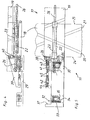
- FIGS. 4 and 5 show a schematic diagram of the device according to the invention for actuating a slidable region 17, for example a switch 11 shown in FIG. 3.
- the device includes a block-shaped stationary region 18 and a relatively movable slide region 19, the displacement of the slide region 19 is brought from a first position 20 to a second position 21 by a hydraulic cylinder 22 arranged on the block side below the slide area 19.
- the hydraulic cylinder 22 has a considerable details tube 23 which is used for the transmission of vertical forces as a guide and is mounted between the frontal areas 24,25 of the block 18. Not shown here is a hold-down device for the tube 23, which is for example mounted elastically.
- the piston rod 26 of the hydraulic cylinder 22 is led out on both sides, wherein the same piston surfaces are given for the flow and return.
- the piston rod 26 is secured by means of nuts 27 on one side to a frame 28, wherein the frame 28 is detachably connected on one side with the slider 19.
- the frame 28 thus transmits the displacement force to the slide 19.
- the latch 32 are extended by means of strong springs 33 and retracted at lugs 34 by hydraulically operated return piston 35.
- the base plate 29 is fastened with screws 36 on the front side 24 of the block 18.
- a double trap 41,42 including a side support 39 which is releasably secured to the slider 19 via screws 40.
- the two traps 41,42 are also made of high-strength material and are provided longitudinally movable.
- the fastening screws 43,44 do not transmit any forces, since the same is taken over by threaded bolt 45, via which a fine adjustment of the slide position in the two end positions 37, 38 can be brought about.
- limit switches two of which serve to control the two end positions 37,38 of the slider 19. Further limit switches check parallel to the end positions of the bolt 32 in the region of the locking elements 30,31. Also not shown is the hydraulic unit, the valve block and the control box.
Landscapes
- Engineering & Computer Science (AREA)
- Mechanical Engineering (AREA)
- Actuator (AREA)
- Vehicle Cleaning, Maintenance, Repair, Refitting, And Outriggers (AREA)
- Switches With Compound Operations (AREA)
- Railway Tracks (AREA)
- Push-Button Switches (AREA)
Description
- Die Erfindung betrifft eine Einrichtung zur Betätigung schiebbarer Bereiche einer Kreuzung oder einer Weiche für Schienenfahrzeuge, insbesondere von Herzstücken, gemäß dem Oberbegriff des Anspruchs 1.
- Eine derartige Kreuzung mit schiebbaren Kreuzungspunkten ist beispielsweise der US-A 403,060 zu entnehmen. Selbige werden über ein auslenkbares Hebelsystem von einer ersten in eine zweite Stellung übergeführt.
- Der DE-A 64856 ist eine Gleiskreuzung mit selbsttätiger Einstellung zum stoßfreien Durchfahren zu entnehmen, die an den Ecken der Kreuzung angebrachte Winkelzwangschienen beinhaltet, welche derart zwangsläufig miteinander verbunden sind, dass sie stets eine Gleisrichtung offen und die kreuzende gesperrt halten.
- Rein mechanische Bewegungsmechanismen, wie sie durch den Stand der Technik dokumentiert werden, sind aufwendig in der Herstellung.
- Durch die GB-A 1,543,800 ist eine Weiche mit verstellbaren Bereichen bekannt geworden, wobei die Verstellung über einen außerhalb des Verstellbereiches vorgesehenen Hydraulikzylinder erfolgt und die Kolbenstange an Bauteilen des Verstellbereiches angreift.
- Hier ist der Nachteil gegeben, dass, bedingt durch die Länge der Kolbenstange, infolge hoher Verstellkräfte es zu Verformungen derselben kommen kann, so dass exakte Positionierungen nur schwer realisierbar sind.
- Ziel des Erfindungsgegenstandes ist es, eine Einrichtung zur Betätigung schiebbarer Bereiche einer Kreuzung oder einer Weiche für Schienenfahrzeuge, insbesondere von Herzstücken, bereitzustellen, die einfach im Aufbau ist, eine kompakte Bauweise beinhaltet und eine exakte Positionierung der verschiebbaren Bereiche in der jeweiligen Endlage ermöglicht.
- Dieses Ziel wird erreicht durch eine Einrichtung zur Betätigung schiebbarer Bereiche einer Kreuzung oder eine Weiche für Schienenfahrzeuge, insbesondere von Herzstücken, mit den Merkmalen des Anspruchs 1.
- Vorteilhafte Weiterbildungen der erfindungsgemäßen Einrichtung sind den Unteransprüchen zu entnehmen.
- Zur Übertragung von Kräften wird als Führung jetzt das Rohr des Antriebszylinders verwendet, wobei eine starre Lagerung des Hydraulikzylinderrohres in den beiden stirnseitigen Endbereichen des Blockes vorgesehen ist. Bedarfsweise können elastisch gelagerte Niederhalteelemente vorgesehen werden. Der Hydraulikzylinder ist somit im Bereich des Kraftangriffes vorgesehen und kann von der Länge her verhältnismäßig kurz ausgeführt werden.
- Der Hydraulikzylinder ist mit seinen beiden Endbereichen an den Blockstirnseiten befestigt. Bedarfsweise kann eine zusätzliche Verschraubung von unten vom Block her vorgesehen werden. Die Kolbenstange ist, einem weiteren Gedanken der Erfindung gemäß, beidseitig herausgeführt, wobei gleiche Kolbenflächen für den Vor- und Rücklauf vorgesehen sind. Die Kolbenstange ist lösbar, bedarfsweise über Muttern, an einem am relativ bewegbaren Schieberbereich gelagerten Rahmen befestigt. Dieser Rahmen wird auf einer Seite lösbar, beispielsweise mittels Schrauben, gehalten, während er sich auf der anderen Seite die Befestigung mit einer Doppelfalle teilt, was später noch konkreter ausgeführt wird. Der Rahmen überträgt somit die Verschiebekraft auf den Schieberbereich.
- Auf einer stabilen Grundplatte sind zwei seitlich wirkende Verriegelungselemente spiegelbildlich angeordnet. Jedes dieser Elemente besitzt einen Riegel, beispielsweise mit quadratischem Querschnitt und besteht aus hochfestem Material. Die Riegel können mittels starker Federn ausgefahren und an Nasen durch hydraulisch betätigte Rückzugkolben wieder eingezogen werden. Die Grundplatte kann lösbar, bedarfsweise mit Schrauben, an einer der Stirnseiten des Blocks befestigt werden. Beidseits der Grundplatte befinden sich Anschläge für die Endstellungen des Schiebers.
- Ebenfalls sehr stabil ausgeführt wird die bereits angesprochene Doppelfalle mit einem Seitenträger, der sowohl an dem Herzstückplattenträger als auch an der Grundplatte selbst befestigt ist. Die beiden Fallen bestehen aus hochfestem Material und sind längsbeweglich vorgesehen. Die Befestigungsschrauben müssen hierbei keine Kräfte übertragen. Selbiges geschieht über Gewindebolzen, welche auch zur Feinjustierung der Schieberposition in den beiden Endstellungen dienen.
- Im Bereich der Einrichtung sind bedarfsweise mehrere Endschalter, wie z. B. Näherungsinitiatoren, vorgesehen, wobei zwei derselben zur Kontrolle der beiden Endstellungen des Schiebers dienen. Weitere Endschalter können bedarfsweise parallel dazu die Endstellungen der Riegel im Bereich der Verriegelungselemente überwachen.
- Nach dem Kommando "Umstellen" wird das Hydraulikaggregat gestartet und sowohl der im Eingriff formschlüssig befindliche als auch der freie Riegel zurückgezogen. Erst wenn dieser Vorgang abgeschlossen ist, geben die in Reihe geschalteten Endschalter das Kommando zur Schieberbewegung durch den Hydraulikzylinder. Nach Durchfahren des vollen Hubs (Kontrolle durch Endschalter) werden die Riegel freigegeben und fahren selbsttätig unter Federdruck aus (Selbsthemmung). Diese Stellung wird abgefragt und - wenn erreicht - das Hydraulikaggregat stillgesetzt. Die Endschalter können bedarfsweise auch eine permanente Überwachung der Endlagen und der Kabelführung (Kabelbruch) durchführen.
- Der Erfindungsgegenstand ist anhand eines Ausführungsbeispieles in der Zeichnung dargestellt und wird wie folgt beschrieben. Es zeigen:
- Figuren 1 und 2
- Herzstücke für einander unter unterschiedlichen Winkeln kreuzende Fahrschienen;
- Figur 3
- Herzstück in einer Weiche;
- Figuren 4 und 5
- Prinzipskizze einer Einrichtung zur Betätigung schiebbarer Bereiche einer Kreuzung.
- Figur 1 zeigt als Prinzipskizze eine Kreuzung 1 von Fahrschienen 2,3, wobei die Fahrschienen 2,3 einander unter einem Winkel von 90° kreuzen. Im Kreuzungsbereich sind unter einem vorgebbaren Winkel zu den Fahrschienen 2,3 bewegbare Herzstücke 4,5,6,7 vorgesehen, die in diesem Beispiel von der dargestellten Position (Fahrschienen 3 befahrbar) in die andere Position (Fahrschienen 2 befahrbar) in Pfeilrichtung bewegbar sind. In diesem Beispiel können die Herzstücke 4,7,5,6 jeweils über einen nicht weiter dargestellten Einzelantrieb in entsprechender Weise bewegt werden. Die Herzstücke 4 bis 7 beinhalten entsprechende Fahrprofile 8,9, so dass ein spurgleiches Profil zu den Fahrschienen 2 und 3 herstellbar ist.
- Figur 2 zeigt als Prinzipskizze ebenfalls eine Kreuzung 10 für einander unter einem Winkel von 45° kreuzende Fahrschienen 2,3. Auch hier sind bewegbare Herzstücke 4,5,6,7 vorgesehen, die entsprechende Fahrspurprofile 8,9 aufweisen und in Pfeilrichtung bewegbar sind. Die Herzstücke 4,5,6,7 verfügen über nicht weiter dargestellte Einzelantriebe. Alle Herzstücke 4-7 werden über besagte Einzelantriebe synchron in die entsprechende Richtung (Pfeil) bewegt.
- Figur 3 zeigt als Prinzipskizze eine Weiche 11 für einander schneidende Fahrschienen 12,13. Im Schnittbereich ist ein quer zu den Fahrschienen 12,13 bewegbares Herzstück 14 vorgesehen, das in die jeweilige Position bewegbar ist. Das Herzstück 14 beinhaltet Fahrrinnenprofile 15,16, so dass nach erfolgter Verschiebung in die jeweilige Endlage ein problemloses Überfahren des Herzstückes 14, respektive der Weiche 11, möglich ist.
- Über hier nicht weiter dargestellte Endschalter wird sichergestellt, dass das jeweilige Herzstück 4 bis 8 bzw. 14 nach erfolgter Umstellung und Verriegelung in der jeweiligen Endstellung ausgerichtet ist.
- Die Figuren 4 und 5 zeigen als Prinzipskizze die erfindungsgemäße Einrichtung zur Betätigung eines schiebbaren Bereiches 17, beispielsweise einer in Figur 3 dargestellten Weiche 11. Die Einrichtung beinhaltet einen blockartig ausgebildeten stationären Bereich 18 sowie einen relativ dazu beweglichen Schieberbereich 19, wobei die Verschiebung des Schieberbereiches 19 von einer ersten Position 20 in eine zweite Position 21 durch einen blockseitig unterhalb des Schieberbereiches 19 angeordneten Hydraulikzylinder 22 herbeigeführt wird. Der Hydraulikzylinder 22 verfügt über ein kurzbauendes Rohr 23, das zur Übertragung von Vertikalkräften als Führung eingesetzt ist und zwischen den stirnseitigen Bereichen 24,25 des Blockes 18 gelagert ist. Hier nicht dargestellt ist eine Niederhalteeinrichtung für das Rohr 23, die beispielsweise elastisch gelagert ist. Die Kolbenstange 26 des Hydraulikzylinders 22 ist beidseitig herausgeführt, wobei gleiche Kolbenflächen für den Vor- und Rücklauf gegeben sind. Die Kolbenstange 26 ist mittels Muttern 27 einseitig an einem Rahmen 28 befestigt, wobei der Rahmen 28 auf einer Seite lösbar mit dem Schieber 19 verbunden ist. Der Rahmen 28 überträgt somit die Verschiebekraft auf den Schieber 19. Auf einer stabilen Grundplatte 29 sind zwei seitlich wirkende Verriegelungselemente 30,31 spiegelbildlich angeordnet. Jedes dieser Elemente 30,31 besitzt einen Riegel 32 aus hochfestem Material. Die Riegel 32 werden mittels starker Federn 33 ausgefahren und an Nasen 34 durch hydraulisch betätigte Rückzugkolben 35 wieder eingezogen. Die Grundplatte 29 ist mit Schrauben 36 an der Stirnseite 24 des Blocks 18 befestigt. Beidseitig der Grundplatte 29 befinden sich Anschlagflächen 37,38 für die jeweilige Endstellung des Schiebers 19. Ferner dargestellt und ebenfalls stabil ausgeführt, ist eine Doppelfalle 41,42, beinhaltend einen Seitenträger 39, der am Schieber 19 lösbar über Schrauben 40 befestigt ist. Die beiden Fallen 41,42 bestehen ebenfalls aus hochfestem Material und sind längsbeweglich vorgesehen. Die Befestigungsschrauben 43,44 übertragen hierbei keine Kräfte, da selbiges durch Gewindebolzen 45 übernommen wird, über welche auch eine Feinjustierung der Schieberposition in den beiden Endstellungen 37,38 herbeiführbar ist.
- Nicht dargestellt sind Endschalter, wobei zwei davon zur Kontrolle der beiden Endstellungen 37,38 des Schiebers 19 dienen. Weitere Endschalter kontrollieren parallel dazu die Endstellungen der Riegel 32 im Bereich der Verriegelungselemente 30,31. Ebenfalls nicht dargestellt ist das Hydraulikaggregat, der Ventilblock und der Schaltkasten.
- Die Betätigung des schiebbaren Bereiches 17 könnte beispielsweise nach folgendem Ablaufschema vorgenommen werden:
- Nach dem Kommando "Umstellen" wird das Hydraulikaggregat gestartet und sowohl der im Eingriff befindliche als auch der freie Riegel 32 werden zurückgezogen. Erst wenn dieser Vorgang abgeschlossen ist, geben die in Reihe geschalteten Endschalter, z. B. Näherungsinitiatoren, das Kommando zur Bewegung des Schiebers 19 durch den Hydraulikzylinder 22. Nach Durchfahren des vollen Hubs (Kontrolle durch Endschalter) werden die Riegel 32 freigegeben und fahren selbsttätig unter Federdruck aus (Selbsthemmung). Diese Stellung wird abgefragt und - wenn erreicht - das Aggregat auf Überwachung geschaltet oder stillgesetzt wird.
Claims (9)
- Einrichtung zur Betätigung schiebbarer Bereiche (17) einer Kreuzung (1,10) oder einer Weiche (11) für Schienenfahrzeuge, insbesondere von Herzstücken (4,5,6,7), beinhaltend mindestens einen blockseitig ausgebildeten stationären Bereich (18) sowie mindestens einen relativ dazu beweglichen Schieberbereich (19), dadurch gekennzeichnet, dass die Bewegung des Schieberbereiches (19) von einer ersten (20) in eine zweite Position (21) durch mindestens einen blockseitig unterhalb des Schieberbereiches (19) angeordneten Hydraulikzylinder (22) herbeiführbar ist.
- Einrichtung nach Anspruch 1, dadurch gekennzeichnet, dass der Hydraulikzylinder (22) mit beidseitig herausführbarer Kolbenstange (26) ausgebildet ist, wobei gleiche Kolbenflächen für Vor- und Rücklauf des Schieberbereiches (19) gegeben sind.
- Einrichtung nach Anspruch 1 oder 2, dadurch gekennzeichnet, dass das Rohr (23) des Hydraulikzylinders (22) als Führung einsetzbar und im Bereich beider Stirnseiten (24,25) des stationären Bereiches (18) ge agert ist.
- Einrichtung nach einem der Ansprüche 1 bis 3, dadurch gekennzeichnet, dass die Verschiebung des Schieberbereiches (19) zwischen definierten Anschlagflächen (37,38) erfolgt.
- Einrichtung nach einem der Ansprüche 1 bis 4, dadurch gekennzeichnet, dass im Bereich zumindest einer der Anschlagflächen (37,38) Verriegelungselemente (30,31), insbesondere in spiegelbildlicher Ausführung, vorgesehen sind.
- Einrichtung nach einem der Ansprüche 1 bis 5, dadurch gekennzeichnet, dass die Verschiebung des Schieberbereiches (19) durch Endschalter überwachbar ist, wobei der Schieberbereich (19) in seinen Endlagen (37,38) formschlüssig verriegelbar ist.
- Einrichtung nach einem der Ansprüche 1 bis 6, dadurch gekennzeichnet, dass am Schieberbereich (19) zumindest einseitig ein Rahmen (28) vorgesehen ist, der zur lösbaren Aufnahme des zugehörigen Endes der Kolbenstange (26) dient.
- Einrichtung nach einem der Ansprüche 1 bis 7, dadurch gekennzeichnet, dass eine Grundplatte (29) lösbar mit dem stationären Bereich (18) verbunden ist, welche die Verriegelungselemente (30,31) aufnimmt, wobei selbige Riegel (32) beinhalten, die mittels Federn (33) selbsttätig ausfahrbar und durch hydraulisch betätigte Rückzugkolben (25) wieder einfahrbar sind.
- Einrichtung nach einem der Ansprüche 1 bis 8, dadurch gekennzeichnet, dass am Schieberbereich (19) ein mit einer Doppelfalle (41,42) versehener Seitenträger (39) lösbar angeordnet ist, wobei die Fallen (41,42) längsbewegbar zwischen den Anschlagflächen (37,38) vorgesehen sind.
Applications Claiming Priority (2)
| Application Number | Priority Date | Filing Date | Title |
|---|---|---|---|
| DE10340784 | 2003-09-02 | ||
| DE10340784A DE10340784B4 (de) | 2003-09-02 | 2003-09-02 | Kreuzung oder Weiche |
Publications (2)
| Publication Number | Publication Date |
|---|---|
| EP1512791A1 EP1512791A1 (de) | 2005-03-09 |
| EP1512791B1 true EP1512791B1 (de) | 2007-02-14 |
Family
ID=34129642
Family Applications (1)
| Application Number | Title | Priority Date | Filing Date |
|---|---|---|---|
| EP04020236A Expired - Lifetime EP1512791B1 (de) | 2003-09-02 | 2004-08-26 | Einrichtung zur Betätigung schiebbarer Bereiche einer Kreuzung oder Weiche |
Country Status (3)
| Country | Link |
|---|---|
| EP (1) | EP1512791B1 (de) |
| AT (1) | ATE353801T1 (de) |
| DE (2) | DE10340784B4 (de) |
Families Citing this family (2)
| Publication number | Priority date | Publication date | Assignee | Title |
|---|---|---|---|---|
| DE102004040878A1 (de) * | 2004-08-11 | 2006-02-23 | Bwg Gmbh & Co. Kg | Kreuzung oder Weiche |
| JP4906294B2 (ja) * | 2005-09-15 | 2012-03-28 | 小野田ケミコ株式会社 | 軌道の切り替え構造及び切り替え方法 |
Family Cites Families (6)
| Publication number | Priority date | Publication date | Assignee | Title |
|---|---|---|---|---|
| DE64856C (de) * | TH. SMITH in Philadelphia, V. St. A | Gleiskreuzung mit selbstthätiger Einstellung zum stofsfreien Durchfahren | ||
| US403060A (en) * | 1889-05-07 | Railway-crossing | ||
| GB1543800A (en) * | 1976-12-31 | 1979-04-04 | Japan Airlines Co | Track switching device for two rail type tracks |
| JP3401258B2 (ja) * | 1993-07-13 | 2003-04-28 | アーサー アーネスト ビショップ | 自動化専用交通システムの分岐装置 |
| DE10215060A1 (de) * | 2002-04-05 | 2003-10-23 | Thyssenkrupp Weichenbau Gmbh | Kreuzung oder Weiche |
| AT411350B (de) * | 2002-08-13 | 2003-12-29 | Vae Eisenbahnsysteme Gmbh | Weichenantrieb für bewegliche herze |
-
2003
- 2003-09-02 DE DE10340784A patent/DE10340784B4/de not_active Expired - Fee Related
-
2004
- 2004-08-26 DE DE502004002885T patent/DE502004002885D1/de not_active Expired - Fee Related
- 2004-08-26 EP EP04020236A patent/EP1512791B1/de not_active Expired - Lifetime
- 2004-08-26 AT AT04020236T patent/ATE353801T1/de not_active IP Right Cessation
Also Published As
| Publication number | Publication date |
|---|---|
| DE10340784A1 (de) | 2005-03-31 |
| ATE353801T1 (de) | 2007-03-15 |
| DE502004002885D1 (de) | 2007-03-29 |
| DE10340784B4 (de) | 2007-04-12 |
| EP1512791A1 (de) | 2005-03-09 |
Similar Documents
| Publication | Publication Date | Title |
|---|---|---|
| DE69121506T2 (de) | Betätigungsvorrichtung für Eisenbahnweichen, insbesondere für Hochgeschwindigkeitsbahnen | |
| EP3477004B1 (de) | Schienensystem mit dehnfuge | |
| EP2829678B1 (de) | Justierbares Laufwerk und Schiebevorrichtung | |
| DE102014006023B4 (de) | Schienensystem, insbesondere für eine Elektropalettenbahn | |
| EP1197319B1 (de) | Keiltrieb | |
| DE1807902A1 (de) | Lagereinrichtung | |
| CH659441A5 (de) | Gleisbremse zur herabsetzung der geschwindigkeit mindestens eines waggons. | |
| EP2346710B1 (de) | Stromabnehmer für ein schienenfahrzeug | |
| EP2576314B1 (de) | Verschluss für weichenstellvorrichtungen | |
| EP3370890B1 (de) | Vorrichtung zum anstellen einer stauchwalze eines stauchgerüsts | |
| DE29709420U1 (de) | Vorrichtung zum Verriegeln von beweglichen Weichenteilen | |
| DE10340784B4 (de) | Kreuzung oder Weiche | |
| EP2030772A2 (de) | Sicherheitseinrichtung an Umformmaschinen | |
| DE19535578B4 (de) | Weichenantrieb mit Innenverschluß | |
| EP1301385B1 (de) | Einrichtung zur mechanischen und elektrischen überprüfung der verstelleinrichtung von weichenantrieben | |
| DE4213288C2 (de) | Hydraulische Druck- und Zugvorrichtung, insbesondere für Eisenbahnschienen | |
| EP1941956A1 (de) | Anbiegepresse zum Biegen eines Blechs bei der Herstellung eines Rohres | |
| DE2712365B2 (de) | Vorrichtung zur Befestigung von Sensoren am Schienenkörper zur Überwachung und/oder Steuerung des Schienenverkehrs | |
| DE3523944C2 (de) | ||
| DE102010021859B4 (de) | Brems- und/oder Feststellvorrichtung eines auf einer Schiene verfahrbaren Schlittens | |
| WO2017157738A1 (de) | Kupplungssystem mit pneumatischer auslenkung | |
| DE473417C (de) | Umstellvorrichtung fuer Strassenbahnweichen | |
| EP3302842B1 (de) | Verfahren zum verstellen eines formabschnittes eines biegewerkzeuges, biegewerkezeug mit einem solchen formabschnitt und verwendung eines solchen biegewerkzeugs | |
| DE684347C (de) | Vorrichtung zur Betaetigung, Verriegelung und UEberwachung von Weichen fuer Eisenbahnen, Strassenbahnen u. dgl. | |
| DE2640636C2 (de) | Vorschubeinrichtung für Lasten |
Legal Events
| Date | Code | Title | Description |
|---|---|---|---|
| PUAI | Public reference made under article 153(3) epc to a published international application that has entered the european phase |
Free format text: ORIGINAL CODE: 0009012 |
|
| AK | Designated contracting states |
Kind code of ref document: A1 Designated state(s): AT BE BG CH CY CZ DE DK EE ES FI FR GB GR HU IE IT LI LU MC NL PL PT RO SE SI SK TR |
|
| AX | Request for extension of the european patent |
Extension state: AL HR LT LV MK |
|
| 17P | Request for examination filed |
Effective date: 20050316 |
|
| AKX | Designation fees paid |
Designated state(s): AT BE BG CH CY CZ DE DK EE ES FI FR GB GR HU IE IT LI LU MC NL PL PT RO SE SI SK TR |
|
| RAP1 | Party data changed (applicant data changed or rights of an application transferred) |
Owner name: THYSSENKRUPP GFT GLEISTECHNIK GMBH |
|
| GRAP | Despatch of communication of intention to grant a patent |
Free format text: ORIGINAL CODE: EPIDOSNIGR1 |
|
| RIC1 | Information provided on ipc code assigned before grant |
Ipc: B61L 5/04 20060101AFI20061006BHEP |
|
| GRAS | Grant fee paid |
Free format text: ORIGINAL CODE: EPIDOSNIGR3 |
|
| GRAA | (expected) grant |
Free format text: ORIGINAL CODE: 0009210 |
|
| AK | Designated contracting states |
Kind code of ref document: B1 Designated state(s): AT BE BG CH CY CZ DE DK EE ES FI FR GB GR HU IE IT LI LU MC NL PL PT RO SE SI SK TR |
|
| PG25 | Lapsed in a contracting state [announced via postgrant information from national office to epo] |
Ref country code: PL Free format text: LAPSE BECAUSE OF FAILURE TO SUBMIT A TRANSLATION OF THE DESCRIPTION OR TO PAY THE FEE WITHIN THE PRESCRIBED TIME-LIMIT Effective date: 20070214 Ref country code: IE Free format text: LAPSE BECAUSE OF FAILURE TO SUBMIT A TRANSLATION OF THE DESCRIPTION OR TO PAY THE FEE WITHIN THE PRESCRIBED TIME-LIMIT Effective date: 20070214 Ref country code: FI Free format text: LAPSE BECAUSE OF FAILURE TO SUBMIT A TRANSLATION OF THE DESCRIPTION OR TO PAY THE FEE WITHIN THE PRESCRIBED TIME-LIMIT Effective date: 20070214 Ref country code: NL Free format text: LAPSE BECAUSE OF FAILURE TO SUBMIT A TRANSLATION OF THE DESCRIPTION OR TO PAY THE FEE WITHIN THE PRESCRIBED TIME-LIMIT Effective date: 20070214 Ref country code: DK Free format text: LAPSE BECAUSE OF FAILURE TO SUBMIT A TRANSLATION OF THE DESCRIPTION OR TO PAY THE FEE WITHIN THE PRESCRIBED TIME-LIMIT Effective date: 20070214 Ref country code: SI Free format text: LAPSE BECAUSE OF FAILURE TO SUBMIT A TRANSLATION OF THE DESCRIPTION OR TO PAY THE FEE WITHIN THE PRESCRIBED TIME-LIMIT Effective date: 20070214 |
|
| REG | Reference to a national code |
Ref country code: GB Ref legal event code: FG4D Free format text: NOT ENGLISH |
|
| REG | Reference to a national code |
Ref country code: CH Ref legal event code: EP |
|
| REF | Corresponds to: |
Ref document number: 502004002885 Country of ref document: DE Date of ref document: 20070329 Kind code of ref document: P |
|
| REG | Reference to a national code |
Ref country code: IE Ref legal event code: FG4D Free format text: LANGUAGE OF EP DOCUMENT: GERMAN |
|
| REG | Reference to a national code |
Ref country code: CH Ref legal event code: NV Representative=s name: E. BLUM & CO. AG PATENT- UND MARKENANWAELTE VSP |
|
| PG25 | Lapsed in a contracting state [announced via postgrant information from national office to epo] |
Ref country code: SE Free format text: LAPSE BECAUSE OF FAILURE TO SUBMIT A TRANSLATION OF THE DESCRIPTION OR TO PAY THE FEE WITHIN THE PRESCRIBED TIME-LIMIT Effective date: 20070514 |
|
| PG25 | Lapsed in a contracting state [announced via postgrant information from national office to epo] |
Ref country code: BG Free format text: LAPSE BECAUSE OF FAILURE TO SUBMIT A TRANSLATION OF THE DESCRIPTION OR TO PAY THE FEE WITHIN THE PRESCRIBED TIME-LIMIT Effective date: 20070515 |
|
| PG25 | Lapsed in a contracting state [announced via postgrant information from national office to epo] |
Ref country code: ES Free format text: LAPSE BECAUSE OF FAILURE TO SUBMIT A TRANSLATION OF THE DESCRIPTION OR TO PAY THE FEE WITHIN THE PRESCRIBED TIME-LIMIT Effective date: 20070525 |
|
| PG25 | Lapsed in a contracting state [announced via postgrant information from national office to epo] |
Ref country code: PT Free format text: LAPSE BECAUSE OF FAILURE TO SUBMIT A TRANSLATION OF THE DESCRIPTION OR TO PAY THE FEE WITHIN THE PRESCRIBED TIME-LIMIT Effective date: 20070716 |
|
| NLV1 | Nl: lapsed or annulled due to failure to fulfill the requirements of art. 29p and 29m of the patents act | ||
| GBV | Gb: ep patent (uk) treated as always having been void in accordance with gb section 77(7)/1977 [no translation filed] |
Effective date: 20070214 |
|
| REG | Reference to a national code |
Ref country code: IE Ref legal event code: FD4D |
|
| EN | Fr: translation not filed | ||
| PG25 | Lapsed in a contracting state [announced via postgrant information from national office to epo] |
Ref country code: SK Free format text: LAPSE BECAUSE OF FAILURE TO SUBMIT A TRANSLATION OF THE DESCRIPTION OR TO PAY THE FEE WITHIN THE PRESCRIBED TIME-LIMIT Effective date: 20070214 Ref country code: GB Free format text: LAPSE BECAUSE OF FAILURE TO SUBMIT A TRANSLATION OF THE DESCRIPTION OR TO PAY THE FEE WITHIN THE PRESCRIBED TIME-LIMIT Effective date: 20070214 |
|
| PLBE | No opposition filed within time limit |
Free format text: ORIGINAL CODE: 0009261 |
|
| STAA | Information on the status of an ep patent application or granted ep patent |
Free format text: STATUS: NO OPPOSITION FILED WITHIN TIME LIMIT |
|
| PG25 | Lapsed in a contracting state [announced via postgrant information from national office to epo] |
Ref country code: CZ Free format text: LAPSE BECAUSE OF FAILURE TO SUBMIT A TRANSLATION OF THE DESCRIPTION OR TO PAY THE FEE WITHIN THE PRESCRIBED TIME-LIMIT Effective date: 20070214 Ref country code: RO Free format text: LAPSE BECAUSE OF FAILURE TO SUBMIT A TRANSLATION OF THE DESCRIPTION OR TO PAY THE FEE WITHIN THE PRESCRIBED TIME-LIMIT Effective date: 20070214 |
|
| 26N | No opposition filed |
Effective date: 20071115 |
|
| BERE | Be: lapsed |
Owner name: THYSSENKRUPP GFT GLEISTECHNIK G.M.B.H. Effective date: 20070831 |
|
| PG25 | Lapsed in a contracting state [announced via postgrant information from national office to epo] |
Ref country code: GR Free format text: LAPSE BECAUSE OF FAILURE TO SUBMIT A TRANSLATION OF THE DESCRIPTION OR TO PAY THE FEE WITHIN THE PRESCRIBED TIME-LIMIT Effective date: 20070515 Ref country code: MC Free format text: LAPSE BECAUSE OF NON-PAYMENT OF DUE FEES Effective date: 20070831 Ref country code: FR Free format text: LAPSE BECAUSE OF FAILURE TO SUBMIT A TRANSLATION OF THE DESCRIPTION OR TO PAY THE FEE WITHIN THE PRESCRIBED TIME-LIMIT Effective date: 20071005 Ref country code: IT Free format text: LAPSE BECAUSE OF FAILURE TO SUBMIT A TRANSLATION OF THE DESCRIPTION OR TO PAY THE FEE WITHIN THE PRESCRIBED TIME-LIMIT Effective date: 20070214 |
|
| PG25 | Lapsed in a contracting state [announced via postgrant information from national office to epo] |
Ref country code: BE Free format text: LAPSE BECAUSE OF NON-PAYMENT OF DUE FEES Effective date: 20070831 |
|
| PGFP | Annual fee paid to national office [announced via postgrant information from national office to epo] |
Ref country code: CH Payment date: 20080814 Year of fee payment: 5 Ref country code: DE Payment date: 20080822 Year of fee payment: 5 Ref country code: LU Payment date: 20080826 Year of fee payment: 5 |
|
| PG25 | Lapsed in a contracting state [announced via postgrant information from national office to epo] |
Ref country code: FR Free format text: LAPSE BECAUSE OF FAILURE TO SUBMIT A TRANSLATION OF THE DESCRIPTION OR TO PAY THE FEE WITHIN THE PRESCRIBED TIME-LIMIT Effective date: 20070214 |
|
| PGFP | Annual fee paid to national office [announced via postgrant information from national office to epo] |
Ref country code: AT Payment date: 20080814 Year of fee payment: 5 |
|
| PG25 | Lapsed in a contracting state [announced via postgrant information from national office to epo] |
Ref country code: EE Free format text: LAPSE BECAUSE OF FAILURE TO SUBMIT A TRANSLATION OF THE DESCRIPTION OR TO PAY THE FEE WITHIN THE PRESCRIBED TIME-LIMIT Effective date: 20070214 |
|
| PG25 | Lapsed in a contracting state [announced via postgrant information from national office to epo] |
Ref country code: CY Free format text: LAPSE BECAUSE OF FAILURE TO SUBMIT A TRANSLATION OF THE DESCRIPTION OR TO PAY THE FEE WITHIN THE PRESCRIBED TIME-LIMIT Effective date: 20070214 |
|
| PG25 | Lapsed in a contracting state [announced via postgrant information from national office to epo] |
Ref country code: TR Free format text: LAPSE BECAUSE OF FAILURE TO SUBMIT A TRANSLATION OF THE DESCRIPTION OR TO PAY THE FEE WITHIN THE PRESCRIBED TIME-LIMIT Effective date: 20070214 Ref country code: HU Free format text: LAPSE BECAUSE OF FAILURE TO SUBMIT A TRANSLATION OF THE DESCRIPTION OR TO PAY THE FEE WITHIN THE PRESCRIBED TIME-LIMIT Effective date: 20070815 |
|
| REG | Reference to a national code |
Ref country code: CH Ref legal event code: PL |
|
| PG25 | Lapsed in a contracting state [announced via postgrant information from national office to epo] |
Ref country code: LI Free format text: LAPSE BECAUSE OF NON-PAYMENT OF DUE FEES Effective date: 20090831 Ref country code: CH Free format text: LAPSE BECAUSE OF NON-PAYMENT OF DUE FEES Effective date: 20090831 |
|
| PG25 | Lapsed in a contracting state [announced via postgrant information from national office to epo] |
Ref country code: AT Free format text: LAPSE BECAUSE OF NON-PAYMENT OF DUE FEES Effective date: 20090826 |
|
| PG25 | Lapsed in a contracting state [announced via postgrant information from national office to epo] |
Ref country code: DE Free format text: LAPSE BECAUSE OF NON-PAYMENT OF DUE FEES Effective date: 20100302 |
|
| PG25 | Lapsed in a contracting state [announced via postgrant information from national office to epo] |
Ref country code: LU Free format text: LAPSE BECAUSE OF NON-PAYMENT OF DUE FEES Effective date: 20090826 |