EP1511936B1 - Zwei-wellen-vakuumpumpe mit synchronmotor - Google Patents
Zwei-wellen-vakuumpumpe mit synchronmotor Download PDFInfo
- Publication number
- EP1511936B1 EP1511936B1 EP03755115A EP03755115A EP1511936B1 EP 1511936 B1 EP1511936 B1 EP 1511936B1 EP 03755115 A EP03755115 A EP 03755115A EP 03755115 A EP03755115 A EP 03755115A EP 1511936 B1 EP1511936 B1 EP 1511936B1
- Authority
- EP
- European Patent Office
- Prior art keywords
- motor
- rotor
- vacuum pump
- shaft vacuum
- stator
- Prior art date
- Legal status (The legal status is an assumption and is not a legal conclusion. Google has not performed a legal analysis and makes no representation as to the accuracy of the status listed.)
- Expired - Lifetime
Links
Images


Classifications
-
- F—MECHANICAL ENGINEERING; LIGHTING; HEATING; WEAPONS; BLASTING
- F04—POSITIVE - DISPLACEMENT MACHINES FOR LIQUIDS; PUMPS FOR LIQUIDS OR ELASTIC FLUIDS
- F04C—ROTARY-PISTON, OR OSCILLATING-PISTON, POSITIVE-DISPLACEMENT MACHINES FOR LIQUIDS; ROTARY-PISTON, OR OSCILLATING-PISTON, POSITIVE-DISPLACEMENT PUMPS
- F04C28/00—Control of, monitoring of, or safety arrangements for, pumps or pumping installations specially adapted for elastic fluids
- F04C28/08—Control of, monitoring of, or safety arrangements for, pumps or pumping installations specially adapted for elastic fluids characterised by varying the rotational speed
-
- F—MECHANICAL ENGINEERING; LIGHTING; HEATING; WEAPONS; BLASTING
- F04—POSITIVE - DISPLACEMENT MACHINES FOR LIQUIDS; PUMPS FOR LIQUIDS OR ELASTIC FLUIDS
- F04C—ROTARY-PISTON, OR OSCILLATING-PISTON, POSITIVE-DISPLACEMENT MACHINES FOR LIQUIDS; ROTARY-PISTON, OR OSCILLATING-PISTON, POSITIVE-DISPLACEMENT PUMPS
- F04C23/00—Combinations of two or more pumps, each being of rotary-piston or oscillating-piston type, specially adapted for elastic fluids; Pumping installations specially adapted for elastic fluids; Multi-stage pumps specially adapted for elastic fluids
- F04C23/02—Pumps characterised by combination with, or adaptation to, specific driving engines or motors
-
- F—MECHANICAL ENGINEERING; LIGHTING; HEATING; WEAPONS; BLASTING
- F04—POSITIVE - DISPLACEMENT MACHINES FOR LIQUIDS; PUMPS FOR LIQUIDS OR ELASTIC FLUIDS
- F04C—ROTARY-PISTON, OR OSCILLATING-PISTON, POSITIVE-DISPLACEMENT MACHINES FOR LIQUIDS; ROTARY-PISTON, OR OSCILLATING-PISTON, POSITIVE-DISPLACEMENT PUMPS
- F04C29/00—Component parts, details or accessories of pumps or pumping installations, not provided for in groups F04C18/00 - F04C28/00
- F04C29/0042—Driving elements, brakes, couplings, transmissions specially adapted for pumps
- F04C29/0085—Prime movers
-
- H—ELECTRICITY
- H02—GENERATION; CONVERSION OR DISTRIBUTION OF ELECTRIC POWER
- H02K—DYNAMO-ELECTRIC MACHINES
- H02K5/00—Casings; Enclosures; Supports
- H02K5/04—Casings or enclosures characterised by the shape, form or construction thereof
- H02K5/12—Casings or enclosures characterised by the shape, form or construction thereof specially adapted for operating in liquid or gas
- H02K5/128—Casings or enclosures characterised by the shape, form or construction thereof specially adapted for operating in liquid or gas using air-gap sleeves or air-gap discs
- H02K5/1282—Casings or enclosures characterised by the shape, form or construction thereof specially adapted for operating in liquid or gas using air-gap sleeves or air-gap discs the partition wall in the air-gap being non cylindrical
-
- H—ELECTRICITY
- H02—GENERATION; CONVERSION OR DISTRIBUTION OF ELECTRIC POWER
- H02K—DYNAMO-ELECTRIC MACHINES
- H02K7/00—Arrangements for handling mechanical energy structurally associated with dynamo-electric machines, e.g. structural association with mechanical driving motors or auxiliary dynamo-electric machines
- H02K7/14—Structural association with mechanical loads, e.g. with hand-held machine tools or fans
-
- F—MECHANICAL ENGINEERING; LIGHTING; HEATING; WEAPONS; BLASTING
- F04—POSITIVE - DISPLACEMENT MACHINES FOR LIQUIDS; PUMPS FOR LIQUIDS OR ELASTIC FLUIDS
- F04C—ROTARY-PISTON, OR OSCILLATING-PISTON, POSITIVE-DISPLACEMENT MACHINES FOR LIQUIDS; ROTARY-PISTON, OR OSCILLATING-PISTON, POSITIVE-DISPLACEMENT PUMPS
- F04C18/00—Rotary-piston pumps specially adapted for elastic fluids
- F04C18/08—Rotary-piston pumps specially adapted for elastic fluids of intermeshing-engagement type, i.e. with engagement of co-operating members similar to that of toothed gearing
- F04C18/12—Rotary-piston pumps specially adapted for elastic fluids of intermeshing-engagement type, i.e. with engagement of co-operating members similar to that of toothed gearing of other than internal-axis type
- F04C18/126—Rotary-piston pumps specially adapted for elastic fluids of intermeshing-engagement type, i.e. with engagement of co-operating members similar to that of toothed gearing of other than internal-axis type with radially from the rotor body extending elements, not necessarily co-operating with corresponding recesses in the other rotor, e.g. lobes, Roots type
-
- F—MECHANICAL ENGINEERING; LIGHTING; HEATING; WEAPONS; BLASTING
- F04—POSITIVE - DISPLACEMENT MACHINES FOR LIQUIDS; PUMPS FOR LIQUIDS OR ELASTIC FLUIDS
- F04C—ROTARY-PISTON, OR OSCILLATING-PISTON, POSITIVE-DISPLACEMENT MACHINES FOR LIQUIDS; ROTARY-PISTON, OR OSCILLATING-PISTON, POSITIVE-DISPLACEMENT PUMPS
- F04C2240/00—Components
- F04C2240/40—Electric motor
-
- F—MECHANICAL ENGINEERING; LIGHTING; HEATING; WEAPONS; BLASTING
- F04—POSITIVE - DISPLACEMENT MACHINES FOR LIQUIDS; PUMPS FOR LIQUIDS OR ELASTIC FLUIDS
- F04C—ROTARY-PISTON, OR OSCILLATING-PISTON, POSITIVE-DISPLACEMENT MACHINES FOR LIQUIDS; ROTARY-PISTON, OR OSCILLATING-PISTON, POSITIVE-DISPLACEMENT PUMPS
- F04C2270/00—Control; Monitoring or safety arrangements
- F04C2270/02—Power
- F04C2270/025—Controlled or regulated
-
- H—ELECTRICITY
- H02—GENERATION; CONVERSION OR DISTRIBUTION OF ELECTRIC POWER
- H02K—DYNAMO-ELECTRIC MACHINES
- H02K21/00—Synchronous motors having permanent magnets; Synchronous generators having permanent magnets
- H02K21/12—Synchronous motors having permanent magnets; Synchronous generators having permanent magnets with stationary armatures and rotating magnets
- H02K21/14—Synchronous motors having permanent magnets; Synchronous generators having permanent magnets with stationary armatures and rotating magnets with magnets rotating within the armatures
Definitions
- the invention relates to a two-shaft vacuum pump with two shafts.
- Roots pump also called Roots pump. Both shafts of the Roots pump each have a rotary piston, which roll off each other without contact. One of the two shafts is driven by an electric drive motor, while the other shaft is synchronized by a gear with the one drive shaft. During the pumping operation, the Roots are strongly heated by the gas compression.
- the seated on the drive shaft motor rotor of the asynchronous motor is designed as a so-called squirrel cage.
- the designed as squirrel cage motor rotor has a relatively large mass and axial length. Because of the inevitably resulting large unbalance forces and the resulting vibrations, the drive shaft must be supported in the region of the drive motor with at least one support bearing. The cooling and lubrication of the or the support bearing is problematic and can be implemented only with great effort, in particular due to their arrangement in the gas-tight sealed area of the vacuum pump.
- EP-A-0 678 966 and EP-A-0 811 766 each disclose two-shaft vacuum pumps driven by a brushless DC drive motor.
- Brushless DC drive motors are usually run at constant speed with constant torque. From the latter document is also known to reduce the engine speed when starting the vacuum pump or at high input pressures and to provide an increased torque.
- a vacuum Roots pump which is driven by a synchronous motor.
- the specific design of the motor rotor is not described. Synchronous motors are in principle unsuitable for vacuum pumps, since the motor rotor is externally excited via heat-generating sliding contacts. A permanent magnet synchronous motor rotor is unsuitable because it provides a constant torque over the speed due to the constant rotor excitation and threatens overheating of the pump rotor at higher speeds. In practice, therefore, no synchronous motors are used to drive vacuum pumps.
- the object of the invention is to provide a two-shaft vacuum pump with an improved drive.
- the drive motor is a synchronous motor, wherein the rotor by at least one permanent magnet permanently is formed energized.
- the permanently excited rotor of a synchronous motor is due to its constantly strong magnetic field and low power loss of low mass and short overall length. In this way, if necessary, all shaft support bearings for additional support of the drive shaft can be omitted, which also eliminates the problems associated with the cooling and lubrication of the support bearing.
- a synchronous motor power limiter which limits the motor power to a predetermined maximum motor power in a lying above a predetermined rated engine speed limiter range.
- the power limiter limits the drive power to a constant value at a speed above the rated speed. This is done by reducing the torque at a shaft speed above the rated speed.
- the torque reduction in the limiter range ensures that the pump can operate at high speeds of up to 8,000 revolutions per minute, but the pump power is limited to a constant maximum value.
- the heat dissipation options for removing the Roots heat are very limited due to the low gas pressure and design. By limiting the motor power and thus the pump power without simultaneous speed limitation overheating of the vacuum pump and in particular the Roots is reliably avoided, at the same time a high gas flow rate remains possible.
- the synchronous motor is operated in the limiter area in the so-called field weakening range.
- the magnetic flux of the permanent magnetic motor rotor is constant, so that a change of the motor torque can only be done by a corresponding control of the stator field.
- Permanent-magnet motor rotors in vacuum pumps have hitherto not been used in practice, because through the over the entire speed range inherently constant torque at high speeds there was an overheating risk for the rotor by increasing the speed of compression heat. These disadvantages made it previously unreasonable or impossible to use a permanent-magnet synchronous motor to drive a vacuum pump. By limiting the motor power in the Beippor Scheme by field weakening operation, the compression-induced heating of the motor rotor is limited at higher speeds to a constant value. Only then is the use of a permanent-magnet synchronous motor for driving a vacuum pump allows and makes sense, which can be used to reach the Beippor Schemees the maximum torque of the motor.
- the power limiter in the Begrenzer Scheme the phase angle between the electric stator and the motor magnetic field to a different angle of 90 degrees.
- the electric stator field is adjusted with its phase position relative to the rotor magnetic field such that the torque is reduced accordingly.
- the power limiter in the limiter range reduces the amount of the stator current. This also reduces the torque M M which is proportional to the stator current.
- the phase angle and the stator current speed dependent With increasing speed in the Beskyr Scheme between the rated speed and the maximum speed of the phase angle or the stator current is changed so that the torque decreases with increasing speed such that the engine power is always approximately constant above the rated speed. As a result, the maximum permissible engine power is provided at each speed, but not exceeded. The vacuum pump is protected against overheating.
- the shaft having the motor rotor is mounted on the engine-side end flying and support bearing free.
- the shaft is supported only by the two main bearings, which are arranged at both longitudinal ends of the pump rotor. The constructions associated with the cooling and lubrication of engine mounts are eliminated.
- the motor rotor has a plurality of permanent magnets, which are arranged on the outside of the motor rotor body. It can also be arranged one or more permanent magnets in corresponding recesses of the motor rotor body.
- the motor rotor preferably has a rotor capsule made of a non-magnetic material, which surrounds the motor rotor body and the permanent magnets on the outside, in particular for operation with gases harmful to the engine materials.
- a rotor capsule made of a non-magnetic material, which surrounds the motor rotor body and the permanent magnets on the outside, in particular for operation with gases harmful to the engine materials.
- the rotor capsule may be made of a non-magnetic metal or plastic.
- a gap pot made of a non-magnetic material is provided on the stator side, which seals the rotor in a gastight manner relative to the stator.
- the containment shell is made of a non-magnetic metal or plastic. Through the containment shell, the pump area is sealed gastight from the environment, with the motor rotor within the pump area and the motor stator outside the pump area.
- the gap between the rotor and stator can be made relatively large. As a result, the use of a split pot is facilitated.
- a pump housing holding the gap pot and a stator housing surrounding the motor stator are formed integrally with one another. As a result, the number of components and the number of joints is reduced.
- the permanent magnet is made of rare earths. With permanent magnets from rare earths strong magnetic fields of long duration can be realized with small size.
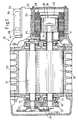
- FIG. 1 shows a two-shaft vacuum pump 10 designed as a roots pump and having two rotor shafts 12, 14.
- Each rotor shaft 12, 14 has a pump rotor 16, 18 designed as a rolling piston.
- a rotor shaft 14 is driven by an electric drive motor 20, while the other shaft 12 is driven by a gear 24 formed by two gears 22, 23 and synchronized with the one rotor shaft 14.
- the drive motor 20 is a synchronous motor and is essentially formed by a permanently excited motor rotor 26 and a motor stator 28 having a plurality of stator coils 30, 31.
- the construction of the motor rotor 26 is shown enlarged in FIG. 2:
- the motor rotor 26 consists of a cup-shaped rotor body 34 which has a plurality of recesses 36 on its outer circumference, in each of which a permanent magnet 38 made of rare earth is glued.
- the entire outer circumference of the rotor 26 is surrounded by a cylindrical rotor capsule 40 made of a non-magnetic material.
- the rotor capsule 40 holds the permanent magnets 38 even at high rotor speeds in the recesses 36 and shields the permanent magnets 38 reliably against corrosive gases and liquids.
- the rotor capsule 40 is made of non-magnetic stainless steel, but may also be made of CFRP or other non-magnetic materials.
- the rotor body 34 may be laminated or solid. Between the rotor 26 and the stator 28, a pot-shaped split can 42 is provided, which is connected to the stator side with a motor housing 44.
- the containment shell seals the motor rotor 26 against the stator 28 in a gastight manner.
- the containment shell 42 is made of non-magnetic stainless steel, but may also consist of CFRP or other non-magnetic materials.
- the motor rotor 26 is by its design as permanent magnet 38 permanently energized rotor of a synchronous machine of small axial length and low mass. This makes it possible that the motor rotor 26 bearing shaft 14 is supported solely by two pump rotor bearings 46, 47 and their motor-side end is formed free of support bearing. The motor rotor 26 is thus stored completely on the fly.
- the motor housing 44 is formed in one piece and has a gap cover 42 holding pump cover 48 and a motor stator 28 surrounding stator 50 on.
- the pump cover 48 holds the gap pot 42 and seals the suction chamber 52 to the outside gas-tight.
- a motor controller 56 is housed in an attached housing 54 on the outside of the motor housing 44. The motor controller 56 controls and regulates the supply of the stator coils 30, 31.
- the engine controller 56 includes a synchronous motor power limiter 58, through which the motor power P M is limited to a predetermined maximum motor power P Mmax above a specified rated motor speed n N , as shown in FIG. As a result, the maximum pump power is limited to a maximum value. This is necessary to avoid overheating of the pump rotors 16, 18.
- the motor controller 56 further includes a frequency converter for starting the drive motor and for speed control.
- ⁇ 2 ⁇ ⁇ n and n is the speed and M M is the motor torque.
- M M is the motor torque.
- the speed range between the rated speed n N , at which the maximum motor power P Mmax is reached, and the maximum speed n max is called the limiter range. Since the magnetic flux generated by the permanently excited motor rotor 26 is always constant, the torque in the Beskyr Scheme can only be done by a corresponding control of the stator coils 30, 31. In the Beskyr Scheme the stator coils 30, 31 are therefore driven so that the torque with increasing speed and is reduced inversely proportional to the speed.
- the drive motor 20 is operated in the limiter area in the so-called field weakening range.
- the stator current is reduced according to the required torque reduction in the Beumbler Scheme.
- the power limiter 58 in the Beumbler Scheme set the phase angle between the motor magnetic field and the electric stator field to a different angle of 90 °.
- the regulation of the motor current or the phase angle in the Beskyr Handbook is always speed-dependent.
- the pump torque Mp and the pump power Pp are always slightly below the engine torque M M or the engine power P M due to friction losses, etc. Overheating of the pump rotor is ruled out given correct dimensioning and adjustment of the maximum pump or motor power.
Landscapes
- Engineering & Computer Science (AREA)
- Mechanical Engineering (AREA)
- General Engineering & Computer Science (AREA)
- Power Engineering (AREA)
- Applications Or Details Of Rotary Compressors (AREA)
- Connection Of Motors, Electrical Generators, Mechanical Devices, And The Like (AREA)
- Permanent Field Magnets Of Synchronous Machinery (AREA)
- Control Of Ac Motors In General (AREA)
- Motor Or Generator Frames (AREA)
- Permanent Magnet Type Synchronous Machine (AREA)
Abstract
Description
- Die Erfindung bezieht sich auf eine Zwei-Wellen-Vakuumpumpe mit zwei Wellen.
- Eine typische Zwei-Wellen-Vakuumpumpe ist die Wälzkolbenpumpe, auch Roots-Pumpe genannt. Beide Wellen der Wälzkolbenpumpe weisen jeweils einen Drehkolben auf, die gegenseitig berührungsfrei abwälzen. Eine der beiden Wellen wird durch einen elektrischen Antriebsmotor angetrieben, während die andere Welle durch ein Getriebe mit der einen Antriebswelle synchronisiert ist. Während des Pumpbetriebes werden die Wälzkolben durch die Gaskompression stark erwärmt.
- Als Antriebsmotoren werden wegen der einfachen Steuer- und Regelbarkeit in der Praxis ausschließlich Asynchronmotoren eingesetzt. Der auf der Antriebswelle sitzende Motorrotor des Asynchronmotors ist als sogenannter Käfigläufer ausgebildet. Der als Käfigläufer ausgebildete Motorrotor hat eine relativ große Masse und axiale Baulänge. Wegen der hieraus zwangsläufig resultierenden großen Unwucht-Kräfte und der daraus resultierenden Vibrationen muss die Antriebswelle im Bereich des Antriebsmotors mit mindestens einem Stützlager abgestützt werden. Die Kühlung und die Schmierung des bzw. der Stützlager ist insbesondere aufgrund ihrer Anordnung im gasdicht abgedichteten Bereich der Vakuumpumpe problematisch und nur mit hohem Aufwand realisierbar.
- In EP-A-0 678 966 und EP-A-0 811 766 werden jeweils Zwei-Wellen-Vakuumpumpen offenbart, die durch einen bürstenlosen DC-Antriebsmotor angetrieben werden. Bürstenlose DC-Antriebsmotoren werden in der Regel bei konstanter Drehzahl mit konstantem Drehmoment gefahren. Aus der letztgenannten Druckschrift ist ferner bekannt, beim Starten der Vakuumpumpe bzw. bei hohen Eingangsdrücken die Motor-Drehzahl zu reduzieren und ein erhöhtes Drehmoment zur Verfügung zu stellen.
- Aus DE-A-38 28 608, die den Stand der Technik offenbart, von der der Oberbegriff des Anspruches 1 ausgeht, ist eine Vakuum-Wälzkolbenpumpe bekannt, die durch einen Synchronmotor angetrieben wird. Die konkrete Ausbildung des Motorrotors ist nicht beschrieben. Synchronmotoren sind für Vakuumpumpen prinzipiell ungeeignet, da der Motorrotor über wärmeerzeugende Schleifkontakte fremderregt wird. Ein permanenterregter Synchronmotor-Rotor ist ungeeignet, da er durch die konstante Rotorerregung ein über die Drehzahl konstantes Drehmoment liefert und bei höheren Drehzahlen eine Überhitzung des Pumpenrotors droht. In der Praxis werden daher keine Synchronmotoren zum Antrieb von Vakuumpumpen eingesetzt.
- Aufgabe der Erfindung ist es, eine Zwei-Wellen-Vakuumpumpe mit einem verbesserten Antrieb zu schaffen.
- Diese Aufgabe wird erfindungsgemäß mit den Merkmalen des Anspruchs 1 gelöst.
- Gemäß der Erfindung ist der Antriebsmotor ein Synchronmotor, wobei der Rotor durch mindestens einen Permanentmagneten permanent erregt ausgebildet ist. Der permanent erregte Rotor eines Synchronmotors ist wegen seines konstant starken Magnetfeldes und der geringen Verlustleistung von geringer Masse und geringer Baulänge. Hierdurch können gegebenenfalls alle Wellen-Stützlager zur zusätzlichen Abstützung der Antriebswelle entfallen, wodurch auch die mit der Kühlung und Schmierung der Stützlager verbundenen Probleme entfallen.
- Durch die geringere Verlustleitung in dem permanent erregten Rotor sind auch die Erwärmung des Rotors und die damit verbundenen Probleme verringert.
- Ferner ist ein Synchronmotor-Leistungsbegrenzer vorgesehen, der in einem oberhalb einer festgelegten Motor-Nenndrehzahl liegenden Begrenzerbereich die Motorleistung auf eine festgelegte maximale Motorleistung begrenzt. Der Leistungsbegrenzer begrenzt die Antriebsleistung bei einer Drehzahl oberhalb der Nenndrehzahl auf einen konstanten Wert. Dies erfolgt dadurch, dass das Drehmoment bei einer Wellen-Drehzahl oberhalb der Nenndrehzahl reduziert ist.
- Die Motorleistung ergibt sich aus

wobei - ω = 2π · n
- PM die Motorleistung
- MM das Motor-Drehmoment bei der Drehzahl n und
- n die Motordrehzahl ist.
- Durch die Drehmoment-Reduzierung im Begrenzerbereich wird sichergestellt, dass die Pumpe auch bei hohen Drehzahlen von bis zu 8.000 Umdrehungen pro Minute arbeiten kann, jedoch die Pumpleistung auf einen konstanten Maximalwert begrenzt ist. Die Wärmeabführungsmöglichkeiten zur Abführung der Wälzkolbenwärme sind wegen des geringen Gasdruckes und konstruktionsbedingt sehr eingeschränkt. Durch Begrenzung der Motorleistung und damit der Pumpleistung ohne gleichzeitige Drehzahlbegrenzung wird eine Überhitzung der Vakuumpumpe und insbesondere der Wälzkolben zuverlässig vermieden, wobei gleichzeitig ein hoher Gas-Volumenstrom ermöglicht bleibt. Der Synchronmotor wird im Begrenzerbereich im sogenannten Feldschwächbereich betrieben. Der magnetische Fluss des permanentmagnetischen Motorrotors ist konstant, so dass eine Änderung des Motordrehmomentes nur durch eine entsprechende Steuerung des Statorfeldes erfolgen kann.
- Permanenterregte Motorrotoren in Vakuumpumpen wurden in der Praxis bisher nicht verwendet, weil durch das über den gesamten Drehzahlbereich prinzipbedingt gleichbleibende Drehmoment bei hohen Drehzahlen eine Überhitzungsgefahr für den Rotor durch mit der Drehzahl zunehmende Kompressionswärme bestand. Diese Nachteile ließen es bisher abwegig bzw. unmöglich erscheinen, zum Antrieb einer Vakuumpumpe einen permanenterregten Synchronmotor einzusetzen. Durch die Begrenzung der Motorleistung im Begrenzerbereich durch Feldschwächbetrieb wird die kompressionsbedingte Erwärmung des Motorrotors bei größeren Drehzahlen auf einen konstanten Wert begrenzt. Erst hierdurch wird die Verwendung eines permanenterregten Synchronmotors zum Antrieb einer Vakuumpumpe ermöglicht und sinnvoll, wobei bis zum Erreichen des Begrenzerbereiches das maximale Drehmoment des Motors genutzt werden kann.
- Gemäß einer bevorzugten Ausgestaltung stellt der Leistungsbegrenzer im Begrenzerbereich den Phasenwinkel zwischen dem elektrischen Statorfeld und dem Motor-Magnetfeld auf einen von 90 Grad verschiedenen Winkel ein. Das elektrische Statorfeld wird mit seiner Phasenlage gegenüber dem Rotor-Magnetfeld derart eingestellt, dass das Drehmoment entsprechend reduziert ist.
- Alternativ oder ergänzend reduziert der Leistungsbegrenzer im Begrenzerbereich den Betrag des Statorstroms. Auch hierdurch wird das Drehmoment MM reduziert, das proportional zum Statorstrom ist.
- Gemäß einer bevorzugten Ausgestaltung stellt der Leistungsbegrenzer im Begrenzerbereich den Phasenwinkel bzw. den Statorstrom drehzahlabhängig ein. Mit zunehmender Drehzahl im Begrenzerbereich zwischen der Nenndrehzahl und der maximalen Drehzahl wird der Phasenwinkel bzw. der Statorstrom so verändert, dass das Drehmoment mit zunehmender Drehzahl derart abnimmt, dass die Motorleistung oberhalb der Nenndrehzahl stets annähernd konstant ist. Hierdurch wird bei jeder Drehzahl die maximal zulässige Motorleistung zur Verfügung gestellt, jedoch nicht überschritten. Die Vakuumpumpe ist vor Überhitzung geschützt.
- Gemäß einer bevorzugten Ausgestaltung ist die den Motorrotor aufweisende Welle am motorseitigen Ende fliegend und stützlagerfrei gelagert. Die Welle wird ausschließlich von den beiden Hauptlagern gelagert, die an beiden Längsenden des Pumpenrotors angeordnet sind. Die mit der Kühlung und Schmierung von Motor-Stützlagern verbundenen Konstruktionen entfallen.
- Vorzugsweise weist der Motorrotor mehrere Permanentmagneten auf, die an der Außenseite des Motorrotorkörpers angeordnet sind. Es kann auch ein oder können mehrere Permanentmagneten in entsprechenden Ausnehmungen des Motorrotorkörpers angeordnet sein.
- Vorzugsweise weist der Motorrotor insbesondere für den Betrieb mit für die Motormaterialien schädlichen Gasen eine Rotorkapsel aus einem nichtmagnetischen Material auf, die den Motorrotorkörper und die Permanentmagneten außen umgibt. Hierdurch werden die außen an dem Motorrotorkörper angeordneten Permanentmagneten gesichert und vor gegebenenfalls aggressiven Gasen und Flüssigkeiten und somit vor Korrosion geschützt. Die Rotorkapsel kann aus einem nichtmagnetischen Metall oder aus Kunststoff bestehen.
- Gemäß einer bevorzugten Ausgestaltung ist statorseitig ein Spalttopf aus einem nichtmagnetischen Material vorgesehen, der den Rotor gegenüber dem Stator gasdicht verschließt. Der Spalttopf besteht aus einem nichtmagnetischen Metall oder Kunststoff. Durch den Spalttopf wird der Pumpenbereich gasdicht gegenüber der Umgebung abgeschlossen, wobei der Motorrotor innerhalb des Pumpenbereiches und der Motorstator außerhalb des Pumpenbereiches liegen. Durch die Verwendung eines permanent erregten Synchronmotors kann der Spalt zwischen Rotor und Stator relativ groß ausgebildet sein. Hierdurch wird der Einsatz eines Spalttopfes erleichtert.
- Gemäß einer bevorzugten Ausgestaltung sind ein den Spalttopf haltender Pumpendeckel und ein den Motorstator umgebendes Statorgehäuse einstückig miteinander ausgebildet. Hierdurch wird die Anzahl der Bauteile und die Anzahl der Fügestellen reduziert.
- Vorzugsweise besteht der Permanentmagnet aus seltenen Erden. Mit Permanentmagneten aus seltenen Erden können starke Magnetfelder von langer Dauer bei kleiner Baugröße realisiert werden.
- Im Folgenden wird unter Bezugnahme auf die Zeichnungen ein Ausführungsbeispiel der Erfindung näher erläutert.
- Es zeigen:
- Fig. 1
- eine Zwei-Wellen-Vakuumpumpe im Längsschnitt,
- Fig. 2
- ein Detail des Antriebsmotors der Vakuumpumpe der Figur 1, und
- Fig. 3
- ein Diagramm mit der Motorleistung, dem Motordrehmoment der Pumpen-Momentenkennlinie und der Pumpenleistung für die Vakuumpumpe der Figuren 1 und 2 mit einem 4,8 kW Antriebsmotor.
- In Figur 1 ist eine als Wälzkolbenpumpe ausgebildete Zwei-Wellen-Vakuumpumpe 10 dargestellt, die zwei Rotor-Wellen 12, 14 aufweist. Jede Rotor-Welle 12, 14 weist einen als Wälzkolben ausgebildeten Pumpenrotor 16, 18 auf. Eine Rotor-Welle 14 ist durch einen elektrischen Antriebsmotor 20 angetrieben, während die andere Welle 12 über ein von zwei Zahnrädern 22, 23 gebildetes Getriebe 24 angetrieben und mit der einen Rotor-Welle 14 synchronisiert ist.
- Der Antriebsmotor 20 ist ein Synchronmotor und wird im Wesentlichen gebildet von einem permanent erregten Motorrotor 26 und einem mehrere Statorspulen 30, 31 aufweisenden Motorstator 28.
- Der Aufbau des Motorrotors 26 ist vergrößert in Figur 2 dargestellt: Der Motorrotor 26 besteht aus einem topfförmigen Rotorkörper 34, der an seinem Außenumfang mehrere Ausnehmungen 36 aufweist, in die jeweils ein aus seltenen Erden bestehender Permanentmagnet 38 eingeklebt ist. Der gesamte Außenumfang des Rotors 26 wird von einer zylindrischen Rotorkapsel 40 aus einem nichtmagnetischen Material umgeben. Die Rotorkapsel 40 hält die Permanentmagnete 38 auch bei hohen Rotordrehzahlen in den Ausnehmungen 36 und schirmt die Permanentmagnete 38 zuverlässig ab gegen korrosionsfördernde Gase und Flüssigkeiten. Die Rotorkapsel 40 besteht aus nichtmagnetischem Edelstahl, kann jedoch auch aus CFK oder anderen nichtmagnetischen Materialien bestehen. Der Rotorkörper 34 kann geblecht oder massiv ausgebildet sein. Zwischen dem Rotor 26 und dem Stator 28 ist ein topfartig ausgebildeter Spalttopf 42 vorgesehen, der statorseitig mit einem Motorgehäuse 44 verbunden ist. Der Spalttopf dichtet den Motorrotor 26 gegenüber dem Stator 28 gasdicht ab. Der Spalttopf 42 besteht aus nichtmagnetischem Edelstahl, kann jedoch auch aus CFK oder anderen nichtmagnetischen Materialien bestehen.
- Der Motorrotor 26 ist durch seine Auslegung als mit Permanentmagneten 38 permanent erregter Rotor einer Synchronmaschine von geringer axialer Baulänge und geringer Masse. Hierdurch wird ermöglicht, dass die den Motorrotor 26 tragende Welle 14 alleine durch zwei Pumpenrotor-Wälzlager 46, 47 getragen wird und ihr motorseitiges Ende stützlagerfrei ausgebildet ist. Der Motorrotor 26 ist also vollständig fliegend gelagert.
- Das Motorgehäuse 44 ist einstückig ausgebildet und weist einen den Spalttopf 42 haltenden Pumpendeckel 48 und ein den Motorstator 28 umgebendes Statorgehäuse 50 auf. Der Pumpendeckel 48 hält den Spalttopf 42 und dichtet den Schöpfraum 52 nach außen gasdicht ab. In einem aufgesetzten Gehäuse 54 an der Außenseite des Motorgehäuses 44 ist eine Motorsteuerung 56 untergebracht. Die Motorsteuerung 56 steuert und regelt die Versorgung der Statorspulen 30, 31.
- Die Motorsteuerung 56 umfasst einen Synchronmotor-Leistungsbegrenzer 58, durch den oberhalb einer festgelegten Motor-Nenndrehzahl nN die Motorleistung PM auf eine festgelegte maximale Motorleistung PMmax begrenzt, wie in Figur 3 dargestellt . Hierdurch wird auch die maximale Pumpenleistung auf einen Maximalwert begrenzt. Dies ist erforderlich, um eine Überhitzung der Pumpenrotoren 16, 18 zu vermeiden. Die Motorsteuerung 56 umfasst ferner einen Frequenzumrichter zum Anfahren des Antriebsmotors und zur Drehzahlregelung.
- Die Motorleistung PM ergibt sich aus

wobei ω = 2π · n und n die Drehzahl und MM das Motor-Drehmoment ist. Bei steigender Drehzahl kann die Motorleistungsbegrenzung also nur durch Reduzieren des Motordrehmoments MM erfolgen. - Der Drehzahlbereich zwischen der Nenndrehzahl nN, bei der die maximale Motorleistung PMmax erreicht ist, und der Maximaldrehzahl nmax wird Begrenzerbereich genannt. Da der von dem permanent erregten Motorrotor 26 erzeugte magnetische Fluss stets konstant ist, kann das Drehmoment im Begrenzerbereich nur durch eine entsprechende Regelung der Statorspulen 30, 31 erfolgen. Im Begrenzerbereich werden die Statorspulen 30, 31 daher derart angesteuert, dass das Drehmoment mit zunehmender Drehzahl und umgekehrt proportional zur Drehzahl verringert ist. Der Antriebsmotor 20 wird im Begrenzerbereich im sogenannten Feldschwächbereich betrieben.
- Hierzu wird im Begrenzerbereich der Statorstrom entsprechend der erforderlichen Drehmomentreduzierung reduziert. Alternativ oder ergänzend kann der Leistungsbegrenzer 58 im Begrenzerbereich den Phasenwinkel zwischen dem Motor-Magnetfeld und dem elektrischen Statorfeld auf einen von 90° verschiedenen Winkel einstellen. Die Regelung des Motorstromes bzw. des Phasenwinkels im Begrenzerbereich erfolgt stets drehzahlabhängig.
- Wie in Figur 3 erkennbar, liegt das Pumpendrehmoment Mp und die Pumpenleistung Pp durch Reibungsverluste etc. stets etwas unterhalb des Motor-Drehmoments MM bzw. der Motorleistung PM. Eine Überhitzung des Pumpenrotors ist bei richtiger Bemessung und Einstellung der maximalen Pumpen- bzw. Motorleistung ausgeschlossen.
Claims (10)
- Zwei-Wellen-Vakuumpumpe mit zwei Wellen (12, 14), wobei eine der Wellen (14) durch einen elektrischen Antriebsmotor (20) angetrieben ist und einen Motorrotor (26) aufweist,
wobei der Antriebsmotor (20) ein Synchronmotor ist,
dadurch gekennzeichnet,
dass der Motorrotor (26) permanent erregt ausgebildet ist, und
dass ein Synchronmotor-Leistungsbegrenzer (58) vorgesehen ist, der in einem oberhalb einer festgelegten Motor-Nenndrehzahl (nN) liegenden Begrenzerbereich die Motorleistung (PM) auf eine festgelegte maximale Motorleistung (PMmax) begrenzt. - Zwei-Wellen-Vakuumpumpe nach.Anspruch 1, dadurch gekennzeichnet, dass der Leistungsbegrenzer (58) im Begrenzerbereich den Phasenwinkel zwischen dem Rotor-Magnetfeld und dem elektrischen Statorfeld auf einen von 90 Grad verschiedenen Winkel einstellt.
- Zwei-Wellen-Vakuumpumpe nach Anspruch 1, dadurch gekennzeichnet, dass der Leistungsbegrenzer (58) im Begrenzerbereich den Statorstrom reduziert.
- Zwei-Wellen-Vakuumpumpe nach Anspruch 1 oder 2, dadurch gekennzeichnet, dass der Leistungsbegrenzer (58) im Begrenzerbereich den Phasenwinkel zwischen dem Rotor-Magnetfeld und dem elektrischen Statorfeld bzw. den Statorstrom drehzahlabhängig einstellt.
- zwei-Wellen-Vakuumpumpe nach einem der Ansprüche 1-4, dadurch gekennzeichnet, dass die angetriebene Rotor-Welle (14) am motorseitigen Ende fliegend und stützlagerfrei gelagert ist.
- Zwei-Wellen-Vakuumpumpe nach einem der Ansprüche 1-5, dadurch gekennzeichnet, dass der Motorrotor (26) mehrere Permanentmagnete (38) aufweist, die an der Außenseite des Motorrotorkörpers (34) angeordnet sind..
- zwei-Wellen-Vakuumpumpe nach Anspruch 6, dadurch gekennzeichnet, dass der Motorrotor (26) eine Rotorkapsel (40) aus einem nichtmagnetischen Material aufweist, die den Motorrotorkörper (34) und die Permanentmagnete (38) außen umgibt.
- Zwei-Wellen-Vakuumpumpe nach einem der Ansprüche 1-7, dadurch gekennzeichnet, dass statorseitig ein Spalttopf (42) aus einem nichtmagnetischen Material vorgesehen ist, der den Motorrotor (26) gegenüber dem Motorstator (28) gasdicht verschließt.
- Zwei-Wellen-Vakuumpumpe nach Anspruch 8, dadurch gekennzeichnet, dass ein den Spalttopf (42) haltender Pumpendeckel (48) und ein den Motorstator (28) umgebendes Statorgehäuse (50) einstückig miteinander ausgebildet sind.
- Zwei-Wellen-Vakuumpumpe nach einem der Ansprüche 7-9, dadurch gekennzeichnet, dass die Rotor-Permanentmagnete (38) aus seltenen Erden bestehen.
Applications Claiming Priority (3)
| Application Number | Priority Date | Filing Date | Title |
|---|---|---|---|
| DE10223869 | 2002-05-29 | ||
| DE10223869A DE10223869A1 (de) | 2002-05-29 | 2002-05-29 | Zwei-Wellen-Vakuumpumpe |
| PCT/EP2003/005402 WO2003100258A1 (de) | 2002-05-29 | 2003-05-23 | Zwei-wellen-vakuumpumpe |
Publications (2)
| Publication Number | Publication Date |
|---|---|
| EP1511936A1 EP1511936A1 (de) | 2005-03-09 |
| EP1511936B1 true EP1511936B1 (de) | 2006-07-12 |
Family
ID=29432412
Family Applications (1)
| Application Number | Title | Priority Date | Filing Date |
|---|---|---|---|
| EP03755115A Expired - Lifetime EP1511936B1 (de) | 2002-05-29 | 2003-05-23 | Zwei-wellen-vakuumpumpe mit synchronmotor |
Country Status (8)
| Country | Link |
|---|---|
| US (1) | US7559752B2 (de) |
| EP (1) | EP1511936B1 (de) |
| JP (1) | JP4518391B2 (de) |
| CN (1) | CN100549425C (de) |
| AU (1) | AU2003232817A1 (de) |
| DE (2) | DE10223869A1 (de) |
| TW (1) | TW200307090A (de) |
| WO (1) | WO2003100258A1 (de) |
Families Citing this family (16)
| Publication number | Priority date | Publication date | Assignee | Title |
|---|---|---|---|---|
| DE102004024554B4 (de) * | 2004-05-18 | 2018-01-25 | Pfeiffer Vacuum Gmbh | Ölgedichtete Drehschiebervakuumpumpe |
| CN100360804C (zh) * | 2005-11-04 | 2008-01-09 | 浙江工业大学 | 一种外环流活塞泵 |
| DE102006022772A1 (de) * | 2006-05-16 | 2007-11-22 | Pfeiffer Vacuum Gmbh | Antriebsanordnung für eine Vakuumpumpe |
| DE102006032765A1 (de) * | 2006-07-14 | 2008-01-17 | Leybold Vacuum Gmbh | Vakuumpumpe |
| FI121645B (fi) * | 2008-04-18 | 2011-02-15 | Randax Oy | Menetelmä sähkökoneen rungon valmistamiseksi, sähkökone ja sähkökoneen runko |
| EP2133991B2 (de) * | 2008-06-09 | 2021-08-25 | Grundfos Management A/S | Kreiselpumpenaggregat |
| DE202009010390U1 (de) * | 2009-07-31 | 2009-10-08 | Busch Produktions Gmbh | Vorrichtung zum lastunabhängigen Beaufschlagen eines Diesel-Rußpartikelfilters mit Druckluft |
| CN102280965B (zh) * | 2010-06-12 | 2013-07-24 | 中国科学院沈阳科学仪器股份有限公司 | 真空泵用屏蔽电机 |
| FR2999357B1 (fr) * | 2012-12-12 | 2021-04-30 | Ge Energy Power Conversion Technology Ltd | Chaine d'entrainement electrique d'un dispositif, et equipement de compression de gaz comprenant une telle chaine |
| DE102013223276A1 (de) * | 2013-11-14 | 2015-05-21 | Oerlikon Leybold Vacuum Gmbh | Regelungsverfahren für einen Hochlauf einer Vakuumpumpe |
| EP3153708B1 (de) * | 2015-10-06 | 2019-07-17 | Pfeiffer Vacuum Gmbh | Scrollpumpe und verfahren zum betreiben einer scrollpumpe |
| CN106499631A (zh) * | 2016-11-04 | 2017-03-15 | 西安航空动力控制科技有限公司 | 一种罗茨风机 |
| CN106678040A (zh) * | 2017-03-08 | 2017-05-17 | 太仓顺达磁力泵科技有限公司 | 一种用于氢燃料电池系统中的氢气循环泵 |
| EP4336713A3 (de) * | 2018-07-19 | 2024-06-05 | Agilent Technologies, Inc. | Vakuumpumpsystem mit ölgeschmierter vakuumpumpe |
| DE102021111297A1 (de) * | 2021-04-30 | 2022-11-03 | CompAir Drucklufttechnik - Zweigniederlassung der Gardner Denver Deutschland GmbH | Antriebssystem für einen mehrstufiger Schraubenverdichter |
| CN114033678B (zh) * | 2021-12-03 | 2024-11-05 | 北京航天石化技术装备工程有限公司 | 无润滑油脂窜漏的高洁净度电动回转容积泵及工作方法 |
Family Cites Families (31)
| Publication number | Priority date | Publication date | Assignee | Title |
|---|---|---|---|---|
| US2640428A (en) * | 1949-05-03 | 1953-06-02 | Dresser Ind | Drive for fluid handling devices of the rotary, positive displacement type |
| US2937807A (en) * | 1956-12-26 | 1960-05-24 | Heraeus Gmbh W C | High vacuum pumps |
| US3234445A (en) * | 1962-04-04 | 1966-02-08 | John F Calvert | A.c.-d.c. dynamo electric machinery |
| US3584276A (en) * | 1969-05-13 | 1971-06-08 | Allis Chalmers Mfg Co | Vehicle electric motor drive system |
| US3956650A (en) * | 1972-06-26 | 1976-05-11 | Sigma Instruments Inc. | Laminar-rotor synchronous inductor motor |
| US4312628A (en) * | 1979-05-21 | 1982-01-26 | Cambridge Thermionic Corporation | Turbomolecular vacuum pump having virtually zero power magnetic bearing assembly with single axis servo control |
| DE3150393A1 (de) | 1981-12-16 | 1983-07-21 | Licentia Patent-Verwaltungs-Gmbh, 6000 Frankfurt | Synchronmotor mit direktumrichter |
| JPS60261386A (ja) * | 1984-06-05 | 1985-12-24 | Toshiba Mach Co Ltd | 交流電動機の速度制御装置 |
| DE3782613T2 (de) * | 1986-11-14 | 1993-03-25 | Toshiba Kawasaki Kk | Hilfsantriebsgeraet fuer eine turbine. |
| DE3828608A1 (de) * | 1988-08-23 | 1990-03-08 | Alcatel Hochvakuumtechnik Gmbh | Vakuumpumpvorrichtung |
| FR2637655B1 (fr) * | 1988-10-07 | 1994-01-28 | Alcatel Cit | Machine rotative du type pompe a vis |
| JPH04178143A (ja) * | 1990-11-07 | 1992-06-25 | Sumitomo Special Metals Co Ltd | 一体型2軸同期駆動モーター |
| DE4100864A1 (de) * | 1991-01-14 | 1992-07-16 | Schaltbau Gmbh | Verfahren zum ansteuern eines elektrischen synchronmotors |
| JP2935479B2 (ja) * | 1991-03-08 | 1999-08-16 | 本田技研工業株式会社 | 永久磁石式同期モータおよびモータシステム |
| DE4121684C2 (de) * | 1991-06-29 | 1999-04-01 | Herold & Co Gmbh | Pumpe |
| CN2104957U (zh) * | 1991-09-22 | 1992-05-20 | 浙江省平阳县万达起重工程设备厂 | 四叶螺旋线状湿式罗茨真空泵 |
| DE4205926A1 (de) * | 1992-02-26 | 1993-09-16 | Magnet Motor Gmbh | Elektrische pumpe |
| JPH0658278A (ja) * | 1992-08-05 | 1994-03-01 | Ebara Corp | 多段スクリュー式真空ポンプ |
| JPH08254193A (ja) * | 1995-03-15 | 1996-10-01 | Ebara Corp | 容積式真空ポンプ |
| JP3294051B2 (ja) * | 1994-04-21 | 2002-06-17 | 株式会社荏原製作所 | 多軸電動機 |
| TW267271B (de) * | 1994-04-21 | 1996-01-01 | Ebara Corp | |
| CN2223372Y (zh) * | 1995-01-02 | 1996-03-27 | 陈飞鸿 | 一种罗茨真空泵 |
| DE69625401T2 (de) * | 1995-03-20 | 2003-10-30 | Ebara Corp., Tokio/Tokyo | Vakuumpumpe |
| EP0738833B1 (de) * | 1995-04-19 | 2000-09-20 | Ebara Corporation | Mehrstufige Verdrängungsvakuumpumpe |
| FR2743456B1 (fr) * | 1996-01-04 | 1998-02-06 | Thomson Csf | Moteur electrique de type synchrone a aimants permanents et vehicule comportant un tel moteur |
| JP3432679B2 (ja) | 1996-06-03 | 2003-08-04 | 株式会社荏原製作所 | 容積式真空ポンプ |
| DE19736907A1 (de) * | 1997-08-25 | 1999-03-04 | Isad Electronic Sys Gmbh & Co | Elektrisch angetriebener Verdichter |
| DE19903069A1 (de) * | 1999-01-27 | 2000-08-03 | Wilo Gmbh | Kontaktierung von Motorwicklungen |
| DE60014780T2 (de) * | 1999-06-30 | 2005-03-10 | Shin-Etsu Chemical Co., Ltd. | Auf seltenen Erden basierender gesinterter Dauermagnet und mit einem solchen Magnet versehener Synchronmotor |
| DE19944194A1 (de) * | 1999-09-15 | 2001-03-22 | Bosch Gmbh Robert | Elektronisch kommutierbarer Motor mit Überlastschutz |
| FR2803451B1 (fr) * | 1999-12-30 | 2002-03-15 | Crouzet Automatismes | Moteur a rotor etanche avec roulement a billes |
-
2002
- 2002-05-29 DE DE10223869A patent/DE10223869A1/de not_active Ceased
-
2003
- 2003-05-23 WO PCT/EP2003/005402 patent/WO2003100258A1/de not_active Ceased
- 2003-05-23 DE DE50304237T patent/DE50304237D1/de not_active Expired - Lifetime
- 2003-05-23 CN CNB038123908A patent/CN100549425C/zh not_active Expired - Fee Related
- 2003-05-23 JP JP2004507687A patent/JP4518391B2/ja not_active Expired - Fee Related
- 2003-05-23 EP EP03755115A patent/EP1511936B1/de not_active Expired - Lifetime
- 2003-05-23 US US10/516,562 patent/US7559752B2/en not_active Expired - Fee Related
- 2003-05-23 AU AU2003232817A patent/AU2003232817A1/en not_active Abandoned
- 2003-05-29 TW TW092114500A patent/TW200307090A/zh unknown
Also Published As
| Publication number | Publication date |
|---|---|
| DE50304237D1 (de) | 2006-08-24 |
| WO2003100258A1 (de) | 2003-12-04 |
| US20050232791A1 (en) | 2005-10-20 |
| JP2005534842A (ja) | 2005-11-17 |
| DE10223869A1 (de) | 2003-12-11 |
| JP4518391B2 (ja) | 2010-08-04 |
| CN100549425C (zh) | 2009-10-14 |
| CN1656318A (zh) | 2005-08-17 |
| AU2003232817A1 (en) | 2003-12-12 |
| EP1511936A1 (de) | 2005-03-09 |
| US7559752B2 (en) | 2009-07-14 |
| TW200307090A (en) | 2003-12-01 |
Similar Documents
| Publication | Publication Date | Title |
|---|---|---|
| EP1511936A1 (de) | Zwei-wellen-vakuumpumpe | |
| DE69503301T2 (de) | Mehrachsen-Elektromotor und mit einem solchen Motor kombinierte Verdrängungspumpe | |
| DE60207246T2 (de) | Schraubenverdichter mit einem motor mit geschalteter reluktanz | |
| EP0520333B1 (de) | Pumpenaggregat | |
| EP2315946B1 (de) | Fluidenergiemaschine | |
| DE69831934T2 (de) | Verbesserungen bei hochgeschwindigkeits - rotorwellen | |
| EP1999375B1 (de) | Verdichtereinheit | |
| EP2080258B1 (de) | Gekapselte elektrische maschine mit flüssigkeitsgekühltem stator | |
| EP3545610B1 (de) | Synchron-maschine mit magnetischer drehfelduntersetzung und flusskonzentration | |
| DE4106060A1 (de) | Pumpe, insbesondere gekapselte medizinische pumpe | |
| EP2017435A2 (de) | Turbomaschine mit elektrischer Maschine und Magnetlagern | |
| EP3508727B1 (de) | Scrollpumpe und verfahren zum betreiben einer scrollpumpe | |
| EP2640977A2 (de) | Magnetisch angetriebene pumpenanordnung mit einer mikropumpe mit zwangsspülung und arbeitsverfahren | |
| DD262310A5 (de) | Elektrische maschine | |
| EP2071186B1 (de) | Vakuumpumpe und Verfahren zum Betrieb | |
| EP1857681B1 (de) | Drehschiebervakuumpumpe mit Spaltrohrmotor | |
| EP1598558B1 (de) | Ölgedichtete Drehschiebervakuumpumpe | |
| EP1812714B1 (de) | Anordnung mit einem luefter und einer pumpe | |
| DE102019215693A1 (de) | Elektrische Maschine und Verfahren zur Herstellung der elektrischen Maschine | |
| DE10144653B4 (de) | Permanent erregte elektromechanische Maschine für den Betrieb in Flüssigkeiten und Gasen | |
| WO2006027043A1 (de) | Anordnung zur förderung von fluiden | |
| EP2558725B1 (de) | Elektrische förderpumpe und verfahren zum antreiben einer elektrischen förderpumpe | |
| EP2226920A2 (de) | Blockheizkraftwerk-Aggregat mit einem Verbrennungskolbenmotor und einer elektrischen Maschine | |
| DE102004003400B4 (de) | Kreiselpumpenaggregat | |
| EP2273655B1 (de) | Elektrische Maschine |
Legal Events
| Date | Code | Title | Description |
|---|---|---|---|
| PUAI | Public reference made under article 153(3) epc to a published international application that has entered the european phase |
Free format text: ORIGINAL CODE: 0009012 |
|
| 17P | Request for examination filed |
Effective date: 20041116 |
|
| AK | Designated contracting states |
Kind code of ref document: A1 Designated state(s): AT BE BG CH CY CZ DE DK EE ES FI FR GB GR HU IE IT LI LU MC NL PT RO SE SI SK TR |
|
| AX | Request for extension of the european patent |
Extension state: AL LT LV MK |
|
| 17Q | First examination report despatched |
Effective date: 20050609 |
|
| DAX | Request for extension of the european patent (deleted) | ||
| RBV | Designated contracting states (corrected) |
Designated state(s): CH DE FR GB IT LI |
|
| GRAP | Despatch of communication of intention to grant a patent |
Free format text: ORIGINAL CODE: EPIDOSNIGR1 |
|
| RTI1 | Title (correction) |
Free format text: DUAL-SHAFT VACUUM PUMP WITH A SYNCHRONOUS MOTOR |
|
| GRAS | Grant fee paid |
Free format text: ORIGINAL CODE: EPIDOSNIGR3 |
|
| GRAA | (expected) grant |
Free format text: ORIGINAL CODE: 0009210 |
|
| AK | Designated contracting states |
Kind code of ref document: B1 Designated state(s): CH DE FR GB IT LI |
|
| PG25 | Lapsed in a contracting state [announced via postgrant information from national office to epo] |
Ref country code: IT Free format text: LAPSE BECAUSE OF FAILURE TO SUBMIT A TRANSLATION OF THE DESCRIPTION OR TO PAY THE FEE WITHIN THE PRESCRIBED TIME-LIMIT;WARNING: LAPSES OF ITALIAN PATENTS WITH EFFECTIVE DATE BEFORE 2007 MAY HAVE OCCURRED AT ANY TIME BEFORE 2007. THE CORRECT EFFECTIVE DATE MAY BE DIFFERENT FROM THE ONE RECORDED. Effective date: 20060712 |
|
| REG | Reference to a national code |
Ref country code: GB Ref legal event code: FG4D Free format text: NOT ENGLISH |
|
| REG | Reference to a national code |
Ref country code: CH Ref legal event code: EP |
|
| REG | Reference to a national code |
Ref country code: CH Ref legal event code: NV Representative=s name: ISLER & PEDRAZZINI AG |
|
| REF | Corresponds to: |
Ref document number: 50304237 Country of ref document: DE Date of ref document: 20060824 Kind code of ref document: P |
|
| GBT | Gb: translation of ep patent filed (gb section 77(6)(a)/1977) |
Effective date: 20061025 |
|
| ET | Fr: translation filed | ||
| PLBI | Opposition filed |
Free format text: ORIGINAL CODE: 0009260 |
|
| PLBI | Opposition filed |
Free format text: ORIGINAL CODE: 0009260 |
|
| 26 | Opposition filed |
Opponent name: THE BOC GROUP PLC Effective date: 20070402 |
|
| PLAX | Notice of opposition and request to file observation + time limit sent |
Free format text: ORIGINAL CODE: EPIDOSNOBS2 |
|
| 26 | Opposition filed |
Opponent name: THE BOC GROUP PLC Effective date: 20070402 Opponent name: PFEIFFER VACUUM GMBH Effective date: 20070412 |
|
| PLAB | Opposition data, opponent's data or that of the opponent's representative modified |
Free format text: ORIGINAL CODE: 0009299OPPO |
|
| R26 | Opposition filed (corrected) |
Opponent name: PFEIFFER VACUUM GMBH Effective date: 20070412 Opponent name: THE BOC GROUP PLC Effective date: 20070402 |
|
| PLAF | Information modified related to communication of a notice of opposition and request to file observations + time limit |
Free format text: ORIGINAL CODE: EPIDOSCOBS2 |
|
| REG | Reference to a national code |
Ref country code: CH Ref legal event code: PCAR Free format text: ISLER & PEDRAZZINI AG;POSTFACH 1772;8027 ZUERICH (CH) |
|
| PLBB | Reply of patent proprietor to notice(s) of opposition received |
Free format text: ORIGINAL CODE: EPIDOSNOBS3 |
|
| PLAB | Opposition data, opponent's data or that of the opponent's representative modified |
Free format text: ORIGINAL CODE: 0009299OPPO |
|
| R26 | Opposition filed (corrected) |
Opponent name: PFEIFFER VACUUM GMBH Effective date: 20070412 Opponent name: THE BOC GROUP PLC Effective date: 20070402 |
|
| RAP2 | Party data changed (patent owner data changed or rights of a patent transferred) |
Owner name: OERLIKON LEYBOLD VACUUM GMBH |
|
| PLCK | Communication despatched that opposition was rejected |
Free format text: ORIGINAL CODE: EPIDOSNREJ1 |
|
| APBM | Appeal reference recorded |
Free format text: ORIGINAL CODE: EPIDOSNREFNO |
|
| APBP | Date of receipt of notice of appeal recorded |
Free format text: ORIGINAL CODE: EPIDOSNNOA2O |
|
| APAH | Appeal reference modified |
Free format text: ORIGINAL CODE: EPIDOSCREFNO |
|
| APAH | Appeal reference modified |
Free format text: ORIGINAL CODE: EPIDOSCREFNO |
|
| APBQ | Date of receipt of statement of grounds of appeal recorded |
Free format text: ORIGINAL CODE: EPIDOSNNOA3O |
|
| PGFP | Annual fee paid to national office [announced via postgrant information from national office to epo] |
Ref country code: IT Payment date: 20100529 Year of fee payment: 8 |
|
| APBU | Appeal procedure closed |
Free format text: ORIGINAL CODE: EPIDOSNNOA9O |
|
| PLBN | Opposition rejected |
Free format text: ORIGINAL CODE: 0009273 |
|
| STAA | Information on the status of an ep patent application or granted ep patent |
Free format text: STATUS: OPPOSITION REJECTED |
|
| PGFP | Annual fee paid to national office [announced via postgrant information from national office to epo] |
Ref country code: CH Payment date: 20100525 Year of fee payment: 8 |
|
| 27O | Opposition rejected |
Effective date: 20100902 |
|
| PGFP | Annual fee paid to national office [announced via postgrant information from national office to epo] |
Ref country code: FR Payment date: 20110603 Year of fee payment: 9 |
|
| PGFP | Annual fee paid to national office [announced via postgrant information from national office to epo] |
Ref country code: GB Payment date: 20110523 Year of fee payment: 9 |
|
| PGFP | Annual fee paid to national office [announced via postgrant information from national office to epo] |
Ref country code: DE Payment date: 20110727 Year of fee payment: 9 |
|
| REG | Reference to a national code |
Ref country code: CH Ref legal event code: PL |
|
| PG25 | Lapsed in a contracting state [announced via postgrant information from national office to epo] |
Ref country code: LI Free format text: LAPSE BECAUSE OF NON-PAYMENT OF DUE FEES Effective date: 20110531 Ref country code: CH Free format text: LAPSE BECAUSE OF NON-PAYMENT OF DUE FEES Effective date: 20110531 |
|
| PG25 | Lapsed in a contracting state [announced via postgrant information from national office to epo] |
Ref country code: IT Free format text: LAPSE BECAUSE OF NON-PAYMENT OF DUE FEES Effective date: 20110523 |
|
| GBPC | Gb: european patent ceased through non-payment of renewal fee |
Effective date: 20120523 |
|
| REG | Reference to a national code |
Ref country code: FR Ref legal event code: ST Effective date: 20130131 |
|
| REG | Reference to a national code |
Ref country code: DE Ref legal event code: R119 Ref document number: 50304237 Country of ref document: DE Effective date: 20121201 |
|
| PG25 | Lapsed in a contracting state [announced via postgrant information from national office to epo] |
Ref country code: FR Free format text: LAPSE BECAUSE OF NON-PAYMENT OF DUE FEES Effective date: 20120531 Ref country code: GB Free format text: LAPSE BECAUSE OF NON-PAYMENT OF DUE FEES Effective date: 20120523 |
|
| PG25 | Lapsed in a contracting state [announced via postgrant information from national office to epo] |
Ref country code: DE Free format text: LAPSE BECAUSE OF NON-PAYMENT OF DUE FEES Effective date: 20121201 |