EP1511903B1 - Sanitäres installationssystem - Google Patents
Sanitäres installationssystem Download PDFInfo
- Publication number
- EP1511903B1 EP1511903B1 EP03759853A EP03759853A EP1511903B1 EP 1511903 B1 EP1511903 B1 EP 1511903B1 EP 03759853 A EP03759853 A EP 03759853A EP 03759853 A EP03759853 A EP 03759853A EP 1511903 B1 EP1511903 B1 EP 1511903B1
- Authority
- EP
- European Patent Office
- Prior art keywords
- tapping
- connection
- mixing device
- plumbing system
- water
- Prior art date
- Legal status (The legal status is an assumption and is not a legal conclusion. Google has not performed a legal analysis and makes no representation as to the accuracy of the status listed.)
- Expired - Lifetime
Links
- 238000009428 plumbing Methods 0.000 title claims abstract 11
- XLYOFNOQVPJJNP-UHFFFAOYSA-N water Substances O XLYOFNOQVPJJNP-UHFFFAOYSA-N 0.000 claims abstract description 52
- 238000010079 rubber tapping Methods 0.000 claims description 21
- 239000011800 void material Substances 0.000 claims 1
- 239000000463 material Substances 0.000 abstract description 2
- 238000009434 installation Methods 0.000 description 17
- 239000011505 plaster Substances 0.000 description 8
- 230000009286 beneficial effect Effects 0.000 description 1
- 230000008878 coupling Effects 0.000 description 1
- 238000010168 coupling process Methods 0.000 description 1
- 238000005859 coupling reaction Methods 0.000 description 1
- 238000005516 engineering process Methods 0.000 description 1
- 238000010438 heat treatment Methods 0.000 description 1
- 239000008141 laxative Substances 0.000 description 1
- 230000002475 laxative effect Effects 0.000 description 1
- 238000009418 renovation Methods 0.000 description 1
- 239000000344 soap Substances 0.000 description 1
Images
Classifications
-
- E—FIXED CONSTRUCTIONS
- E03—WATER SUPPLY; SEWERAGE
- E03C—DOMESTIC PLUMBING INSTALLATIONS FOR FRESH WATER OR WASTE WATER; SINKS
- E03C1/00—Domestic plumbing installations for fresh water or waste water; Sinks
- E03C1/02—Plumbing installations for fresh water
Definitions
- the invention relates to a sanitary Installation system for the supply of Residential units with hot and cold water.
- sanitary installation systems of this kind known in which at least two lines, namely a hot water pipe and a cold water leading pipe from one central supply point forth throughout Residential unit must be installed.
- the individual taps in this case with a mixed water battery for example, a two-handle fitting or be fitted with a single lever mixer the corresponding tap cold water or Hot water or mixed water are tapped can.
- the corresponding installation effort is significant, not only in the case of New installation in new buildings one plays a vital role but just now and especially in the renovation of Old buildings leads to significant costs.
- Identification number JP 59231351 A is a Installation system known in which several Taps via a ring line with hot water be supplied. The water temperature is over corresponding control elements adjustable on a heating device act by means of which the Water is heated up.
- the invention is based on the object, a sanitary installation system of this kind for To provide, which with considerable lower material usage and using from simple fittings to the tapping of Hot water or cold water or mixed water allows the individual taps.
- the central distributor fitting has a Mixing device that is decentralized from the individual taps off and set can be controlled.
- the distributor fitting is only via a single pipe as continuous string line with all decentralized taps of the Housing unit connected and as well with the Mixed water drain connection of the central Distribution fitting.
- Remote control parts are provided by means of which the central distributor fitting, in particular the local mixing device to be controlled can.
- the controller can be wireless or wired signals.
- the individual taps with each other and / or with the mixing device via an electrical or electronic Priority, so only the Signals from the remote control part of the Mixing device processable or receivable are, which is actuated first or which determines the lowest mixing temperature has, with the priority circuit either by Operation of the remote control unit at closed tap or by closing the tapping point is reset.
- the priority by an electronic OR connection of the decentralized tap points formed with the central mixing device is that by pressing the first-operated Remote control unit or the first operated Zapfstelle is set and by renewed Actuation of the first operated remote control unit or by closing the first operated one Zapfstelle is reset.
- a preferred training is seen therein that the plaster installed on plaster or Pipe parts containing the mixing device with the taps connects as a handle is trained.
- the piping or Pipeline parts installed on plaster are in the user's field of vision, be particularly shapely, especially with regard to their Surface finish. They can do this Pipes also a second function fulfill, namely as a handle or serve the same, for example as When the handle. Furthermore, at the Piping accessories, e.g. Soap dishes, Towel rack or the like Equipment elements are attached.
- the pipeline, the mixing device with the taps connects, at least one lead cavity for performing electrical supply and / or control lines and / or Having data lines.
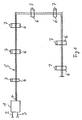
- FIG. 1 is a sanitary Installation system for the supply of Units with hot and cold water shown.
- the Installation system consists of a strand a single-pipe 5. This strand is through the entire residential unit led. Of this Strand 5 go the individual decentralized Taps 6 off.
- the tubing 5 can for example, on plaster or partially or completely plastered. at a surface installation, it is beneficial if the Taps 6 immediately at the corresponding Wall surface are attached.
- Each tap 6 is through a simple Tap valve or a simple outlet fitting educated.
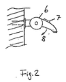
- each tap has 6 a remote control part 7.
- the remote control unit can objectively with the tapping point 6 a Form unity or in the immediate vicinity the tapping point 6 building side or strand 5 be attached.
- the remote control parts 7 are with the mixing device of the central Distributor fitting 1 wireless or wired or mechanically via tension cables or Linkage in conjunction, so that the Mixing device by pressing the Remote control parts 7 can be adjusted. It is thus from the corresponding tapping point 6 to select the appropriate temperature in the mixed water delivery 4 in the Pipe strand 5 is fed.
Landscapes
- Health & Medical Sciences (AREA)
- Life Sciences & Earth Sciences (AREA)
- Engineering & Computer Science (AREA)
- Hydrology & Water Resources (AREA)
- Public Health (AREA)
- Water Supply & Treatment (AREA)
- Domestic Plumbing Installations (AREA)
- Paper (AREA)
- Domestic Hot-Water Supply Systems And Details Of Heating Systems (AREA)
- Absorbent Articles And Supports Therefor (AREA)
- Bidet-Like Cleaning Device And Other Flush Toilet Accessories (AREA)
- Sanitary Device For Flush Toilet (AREA)
- Audible And Visible Signals (AREA)
- Alarm Systems (AREA)
Description
- Figur 1
- ein erfindungsgemäßes Installationssystem schematisch;
- Figur 2
- eine Einzelheit in Seitenansicht.
Claims (6)
- Sanitäres Installationssystem zur Versorgung von Wohneinheiten mit Kalt- und Warmwasser, bestehend aus einer zentralen Verteilerarmatur (1) mit Kaltwasserzulaufanschluss (2), Warmwasserzulaufanschluss (3) und Mischwasserablaufanschluss (4) sowie einer Mischvorrichtung durch die der Mischwasserablaufanschluss (4) Kaltwasser, Warmwasser oder Mischwasser aus Kalt- und Warmwasser gespeist ist, und aus einer oder mehreren Zapfstellen (6), wobei jede Zapfstelle (6) durch ein Zapfventil oder eine einfache Auslaufarmatur mit Absperrhahn gebildet ist und jede Zapfstelle (6) ein Fernbedienteil (7) aufweist oder in der Nähe jeder Zapfstelle (6) ein Fernbedienteil (7) angeordnet ist, mittels dessen die Mischvorrichtung der zentralen Verteilerarmatur (1) elektrisch drahtlos oder drahtgebunden oder mechanisch ferneinstellbar ist, dadurch gekennzeichnet, dass nur ein Strang (5) einer Wasser führenden Leitung vorgesehen ist, der an dem Mischwasserablaufanschluss (4) angeschlossen ist, und dass der Strang (5) unter Putz, auf Putz oder teilweise unter und auf Putz zu allen einzelnen dezentralen Zapfstellen (6) der Wohneinheit geführt ist, wobei der Strang (5) durch eine Einrohrleitung gebildet ist.
- Sanitäres Installationssystem nach Anspruch 1, dadurch gekennzeichnet, dass die einzelnen Zapfstellen (6) miteinander und/oder mit der Mischvorrichtung über eine elektrische oder elektronische Vorrangschaltung verknüpft sind, sodass nur die Signale des Fernbedienteils (7) von der Mischvorrichtung verarbeitbar oder empfangbar sind, welches als erstes betätigt ist oder welches die niedrigste Mischtemperatur bestimmt hat, wobei die Vorrangschaltung entweder durch Betätigung des Fernbedienteils (7) bei geschlossener Zapfstelle (6) oder durch Schließen der Zapfstelle (6) zurückgesetzt ist.
- Sanitäres Installationssystem nach Anspruch 2, dadurch gekennzeichnet, dass die Vorrangschaltung durch eine elektronische ODER-Verknüpfung der dezentralen Zapfstellen (6) mit der zentralen Mischvorrichtung gebildet ist, die durch Betätigung des erstbetätigten Fernbedienteils (7) oder der erstbetätigten Zapfstelle (6) gesetzt ist und durch erneute Betätigung des erstbetätigten Fernbedienteils (7) oder durch Schließen der erstbetätigten Zapfstelle (6) zurückgesetzt ist.
- Sanitäres Installationssystem nach einem der Ansprüche 1 bis 3, dadurch gekennzeichnet, dass der auf Putz installierte als Einrohrleitung gebildete Strang (5) oder Rohrleitungsteile, der die Mischvorrichtung mit den Zapfstellen (6) verbindet oder verbinden als Haltegriff ausgebildet ist oder sind.
- Sanitäres Installationssystem nach einem der Ansprüche 1 bis 4, dadurch gekennzeichnet, dass der als Einrohrleitung gebildete Strang (5), der die Mischvorrichtung mit den Zapfstellen (6) verbindet, mindestens einen weiteren Leitungshohlraum zum Durchführen von elektrischen Versorgungs- und/oder Steuerleitungen und/oder Datenleitungen aufweist.
- Sanitäres Installationssystem nach einem der Ansprüche 1 bis 5, dadurch gekennzeichnet, dass mindestens eine Zapfstelle (6) durch eine gegenüber dem zuführenden und abführenden als Einrohrleitung gebildeten Strang (5) verdrehbare Auslaufarmatur gebildet ist.
Priority Applications (1)
| Application Number | Priority Date | Filing Date | Title |
|---|---|---|---|
| SI200330144T SI1511903T1 (sl) | 2002-06-12 | 2003-06-12 | Sanitarna napeljava |
Applications Claiming Priority (3)
| Application Number | Priority Date | Filing Date | Title |
|---|---|---|---|
| DE20209321U | 2002-06-12 | ||
| DE20209321U DE20209321U1 (de) | 2002-06-12 | 2002-06-12 | Reling z.B. für Bäder und Nasszellen mit integrierter Technik |
| PCT/DE2003/001977 WO2003107527A2 (de) | 2002-06-12 | 2003-06-12 | Sanitäres installationssystem |
Publications (2)
| Publication Number | Publication Date |
|---|---|
| EP1511903A2 EP1511903A2 (de) | 2005-03-09 |
| EP1511903B1 true EP1511903B1 (de) | 2005-10-19 |
Family
ID=7972221
Family Applications (1)
| Application Number | Title | Priority Date | Filing Date |
|---|---|---|---|
| EP03759853A Expired - Lifetime EP1511903B1 (de) | 2002-06-12 | 2003-06-12 | Sanitäres installationssystem |
Country Status (7)
| Country | Link |
|---|---|
| EP (1) | EP1511903B1 (de) |
| AT (1) | ATE307230T1 (de) |
| AU (1) | AU2003250261A1 (de) |
| DE (2) | DE20209321U1 (de) |
| ES (1) | ES2247558T3 (de) |
| RU (1) | RU2005100046A (de) |
| WO (1) | WO2003107527A2 (de) |
Families Citing this family (3)
| Publication number | Priority date | Publication date | Assignee | Title |
|---|---|---|---|---|
| CH704187B1 (de) | 2010-12-06 | 2021-11-15 | Eliane Zoccolillo Luethi | Sanitärsystem mit einer Mischzentrale. |
| DE102010055804A1 (de) * | 2010-12-23 | 2012-06-28 | Ideal-Standard International B.V.B.A. | Modulares Unterputz-System mit einem zentralen Unterputz-Mischmodul |
| DE102010055805A1 (de) * | 2010-12-23 | 2012-06-28 | Ideal-Standard International Bvba | Unterputz-Einbaukasten für ein eine elektronisch ansteuerbare Temperatur- und Volumensteuereinheit aufwesendes Mischmodul |
Family Cites Families (8)
| Publication number | Priority date | Publication date | Assignee | Title |
|---|---|---|---|---|
| JPS59231351A (ja) * | 1983-06-10 | 1984-12-26 | Matsushita Electric Ind Co Ltd | 複数の遠隔制御器を備えた給湯機 |
| GB2172413B (en) * | 1985-03-12 | 1988-11-02 | Caradon Mira Ltd | Water supply installation for ablutionary purposes |
| EP0414691A4 (en) * | 1988-03-22 | 1992-05-06 | Ryemetal Forgings (Vic) Pty. Ltd. | Electronic tapware |
| US5438714A (en) * | 1989-10-31 | 1995-08-08 | Bauer Industries, Inc. | Fresh water manifold distribution system and method |
| US5107883A (en) * | 1990-03-02 | 1992-04-28 | Bauer Industries, Inc. | Pinch valve control system for water line isolation and method |
| JPH04177019A (ja) * | 1990-11-13 | 1992-06-24 | Matsushita Electric Ind Co Ltd | 給湯機の制御装置 |
| US5504950A (en) * | 1994-07-07 | 1996-04-09 | Adams Rite Sabre International | Variable temperature electronic water supply system |
| CN2235581Y (zh) * | 1996-02-08 | 1996-09-18 | 广东省中南科信电子燃气具公司 | 无线遥控式全自动燃气热水器 |
-
2002
- 2002-06-12 DE DE20209321U patent/DE20209321U1/de not_active Expired - Lifetime
-
2003
- 2003-06-12 RU RU2005100046/03A patent/RU2005100046A/ru not_active Application Discontinuation
- 2003-06-12 DE DE50301436T patent/DE50301436D1/de not_active Expired - Lifetime
- 2003-06-12 AU AU2003250261A patent/AU2003250261A1/en not_active Abandoned
- 2003-06-12 EP EP03759853A patent/EP1511903B1/de not_active Expired - Lifetime
- 2003-06-12 WO PCT/DE2003/001977 patent/WO2003107527A2/de not_active Ceased
- 2003-06-12 AT AT03759853T patent/ATE307230T1/de not_active IP Right Cessation
- 2003-06-12 ES ES03759853T patent/ES2247558T3/es not_active Expired - Lifetime
Also Published As
| Publication number | Publication date |
|---|---|
| AU2003250261A1 (en) | 2003-12-31 |
| WO2003107527A2 (de) | 2003-12-24 |
| ES2247558T3 (es) | 2006-03-01 |
| EP1511903A2 (de) | 2005-03-09 |
| AU2003250261A8 (en) | 2003-12-31 |
| DE50301436D1 (de) | 2006-03-02 |
| DE20209321U1 (de) | 2002-11-21 |
| RU2005100046A (ru) | 2005-06-10 |
| WO2003107527A3 (de) | 2004-02-19 |
| ATE307230T1 (de) | 2005-11-15 |
Similar Documents
| Publication | Publication Date | Title |
|---|---|---|
| EP2649246B1 (de) | Sanitärsystem mit einer mischzentrale | |
| EP3935224B1 (de) | Sanitärarmatur mit einem zweiwegeventil | |
| DE102014208261B4 (de) | Trink- und Brauchwassersystem eines Gebäudes und Verfahren zur Steuerung des Trink- und Brauchwassersystems | |
| EP3321594B1 (de) | Wassersystem mit einem durchflusserwärmer und einer spülstation | |
| EP3321428A1 (de) | Sanitärarmatur mit bypass-ventil | |
| WO2020104230A1 (de) | Sanitärarmatur mit mischventil und ventil | |
| EP1511903B1 (de) | Sanitäres installationssystem | |
| DE102019107179A1 (de) | Verfahren zur Wasserversorgung von mindestens einer Wasserentnahmestelle mit Kalt- und Warmwasser | |
| AT508007B1 (de) | Montageblock für den anschluss von geräten | |
| AT507426B1 (de) | Montageblock für den anschluss von geräten | |
| DE3116502C2 (de) | ||
| DE102016013555A1 (de) | Wassersparsystem | |
| EP2468964A1 (de) | Modulares Unterputz-System mit einem zentralen Unterputz-Mischmodul | |
| DE19941285C2 (de) | Doppelrohrsystem als Rohr im Rohr zum Erstellen von Verteil- und Zirkulationssystemen für Trinkwasser in Verbindung mit Trinkwassererwärmungsanlagen | |
| AT302U2 (de) | Montageblock fuer den anschluss von geraeten | |
| CH698596B1 (de) | Sanitäre Hausinstallation. | |
| DE202014104134U1 (de) | Wohnungsstation | |
| DE60008780T2 (de) | Modularer gasbeheizter kombikessel | |
| DE20122076U1 (de) | Warmwasseranlage mit einem Elektro-Druchlauferhitzer | |
| DE102014008319B4 (de) | Raumtemperatur-Regelung für eine Flächenheizung | |
| EP1435480A2 (de) | Sanitärarmatur | |
| AT409574B (de) | Warmwasseranlage | |
| DE102024111354A1 (de) | Sanitärinstallation und Trinkwasserversorgungsstation | |
| EP2386693A1 (de) | Waschtischarmatur mit Sicherheitstemperaturbegrenzerelement | |
| DE102021133804A1 (de) | Warmwassersystem |
Legal Events
| Date | Code | Title | Description |
|---|---|---|---|
| PUAI | Public reference made under article 153(3) epc to a published international application that has entered the european phase |
Free format text: ORIGINAL CODE: 0009012 |
|
| 17P | Request for examination filed |
Effective date: 20041201 |
|
| AK | Designated contracting states |
Kind code of ref document: A2 Designated state(s): AT BE BG CH CY CZ DE DK EE ES FI FR GB GR HU IE IT LI LU MC NL PT RO SE SI SK TR |
|
| AX | Request for extension of the european patent |
Extension state: AL LT LV MK |
|
| GRAP | Despatch of communication of intention to grant a patent |
Free format text: ORIGINAL CODE: EPIDOSNIGR1 |
|
| GRAS | Grant fee paid |
Free format text: ORIGINAL CODE: EPIDOSNIGR3 |
|
| GRAA | (expected) grant |
Free format text: ORIGINAL CODE: 0009210 |
|
| AK | Designated contracting states |
Kind code of ref document: B1 Designated state(s): AT BE BG CH CY CZ DE DK EE ES FI FR GB GR HU IE IT LI LU MC NL PT RO SE SI SK TR |
|
| AX | Request for extension of the european patent |
Extension state: LT LV |
|
| PG25 | Lapsed in a contracting state [announced via postgrant information from national office to epo] |
Ref country code: IE Free format text: LAPSE BECAUSE OF FAILURE TO SUBMIT A TRANSLATION OF THE DESCRIPTION OR TO PAY THE FEE WITHIN THE PRESCRIBED TIME-LIMIT Effective date: 20051019 Ref country code: FI Free format text: LAPSE BECAUSE OF FAILURE TO SUBMIT A TRANSLATION OF THE DESCRIPTION OR TO PAY THE FEE WITHIN THE PRESCRIBED TIME-LIMIT Effective date: 20051019 Ref country code: SK Free format text: LAPSE BECAUSE OF FAILURE TO SUBMIT A TRANSLATION OF THE DESCRIPTION OR TO PAY THE FEE WITHIN THE PRESCRIBED TIME-LIMIT Effective date: 20051019 Ref country code: CZ Free format text: LAPSE BECAUSE OF FAILURE TO SUBMIT A TRANSLATION OF THE DESCRIPTION OR TO PAY THE FEE WITHIN THE PRESCRIBED TIME-LIMIT Effective date: 20051019 |
|
| REG | Reference to a national code |
Ref country code: GB Ref legal event code: FG4D Free format text: NOT ENGLISH |
|
| REG | Reference to a national code |
Ref country code: CH Ref legal event code: EP |
|
| REG | Reference to a national code |
Ref country code: IE Ref legal event code: FG4D Free format text: LANGUAGE OF EP DOCUMENT: GERMAN |
|
| PG25 | Lapsed in a contracting state [announced via postgrant information from national office to epo] |
Ref country code: GR Free format text: LAPSE BECAUSE OF FAILURE TO SUBMIT A TRANSLATION OF THE DESCRIPTION OR TO PAY THE FEE WITHIN THE PRESCRIBED TIME-LIMIT Effective date: 20060119 Ref country code: SE Free format text: LAPSE BECAUSE OF FAILURE TO SUBMIT A TRANSLATION OF THE DESCRIPTION OR TO PAY THE FEE WITHIN THE PRESCRIBED TIME-LIMIT Effective date: 20060119 Ref country code: DK Free format text: LAPSE BECAUSE OF FAILURE TO SUBMIT A TRANSLATION OF THE DESCRIPTION OR TO PAY THE FEE WITHIN THE PRESCRIBED TIME-LIMIT Effective date: 20060119 Ref country code: BG Free format text: LAPSE BECAUSE OF FAILURE TO SUBMIT A TRANSLATION OF THE DESCRIPTION OR TO PAY THE FEE WITHIN THE PRESCRIBED TIME-LIMIT Effective date: 20060119 |
|
| GBT | Gb: translation of ep patent filed (gb section 77(6)(a)/1977) |
Effective date: 20060130 |
|
| REG | Reference to a national code |
Ref country code: ES Ref legal event code: FG2A Ref document number: 2247558 Country of ref document: ES Kind code of ref document: T3 |
|
| REF | Corresponds to: |
Ref document number: 50301436 Country of ref document: DE Date of ref document: 20060302 Kind code of ref document: P |
|
| REG | Reference to a national code |
Ref country code: RO Ref legal event code: EPE |
|
| PG25 | Lapsed in a contracting state [announced via postgrant information from national office to epo] |
Ref country code: PT Free format text: LAPSE BECAUSE OF FAILURE TO SUBMIT A TRANSLATION OF THE DESCRIPTION OR TO PAY THE FEE WITHIN THE PRESCRIBED TIME-LIMIT Effective date: 20060320 |
|
| PG25 | Lapsed in a contracting state [announced via postgrant information from national office to epo] |
Ref country code: HU Free format text: LAPSE BECAUSE OF FAILURE TO SUBMIT A TRANSLATION OF THE DESCRIPTION OR TO PAY THE FEE WITHIN THE PRESCRIBED TIME-LIMIT Effective date: 20060420 |
|
| REG | Reference to a national code |
Ref country code: IE Ref legal event code: FD4D |
|
| PG25 | Lapsed in a contracting state [announced via postgrant information from national office to epo] |
Ref country code: MC Free format text: LAPSE BECAUSE OF NON-PAYMENT OF DUE FEES Effective date: 20060630 Ref country code: BE Free format text: LAPSE BECAUSE OF NON-PAYMENT OF DUE FEES Effective date: 20060630 |
|
| ET | Fr: translation filed | ||
| PLBE | No opposition filed within time limit |
Free format text: ORIGINAL CODE: 0009261 |
|
| STAA | Information on the status of an ep patent application or granted ep patent |
Free format text: STATUS: NO OPPOSITION FILED WITHIN TIME LIMIT |
|
| 26N | No opposition filed |
Effective date: 20060720 |
|
| PGFP | Annual fee paid to national office [announced via postgrant information from national office to epo] |
Ref country code: SI Payment date: 20070612 Year of fee payment: 5 |
|
| PGFP | Annual fee paid to national office [announced via postgrant information from national office to epo] |
Ref country code: AT Payment date: 20070629 Year of fee payment: 5 Ref country code: NL Payment date: 20070629 Year of fee payment: 5 |
|
| PGFP | Annual fee paid to national office [announced via postgrant information from national office to epo] |
Ref country code: GB Payment date: 20070613 Year of fee payment: 5 |
|
| BERE | Be: lapsed |
Owner name: GEBHARD, HANS Effective date: 20060630 |
|
| PGFP | Annual fee paid to national office [announced via postgrant information from national office to epo] |
Ref country code: RO Payment date: 20070612 Year of fee payment: 5 |
|
| REG | Reference to a national code |
Ref country code: CH Ref legal event code: PL |
|
| PG25 | Lapsed in a contracting state [announced via postgrant information from national office to epo] |
Ref country code: CH Free format text: LAPSE BECAUSE OF NON-PAYMENT OF DUE FEES Effective date: 20070630 Ref country code: LI Free format text: LAPSE BECAUSE OF NON-PAYMENT OF DUE FEES Effective date: 20070630 |
|
| PGFP | Annual fee paid to national office [announced via postgrant information from national office to epo] |
Ref country code: FR Payment date: 20070621 Year of fee payment: 5 |
|
| PG25 | Lapsed in a contracting state [announced via postgrant information from national office to epo] |
Ref country code: EE Free format text: LAPSE BECAUSE OF FAILURE TO SUBMIT A TRANSLATION OF THE DESCRIPTION OR TO PAY THE FEE WITHIN THE PRESCRIBED TIME-LIMIT Effective date: 20051019 |
|
| PG25 | Lapsed in a contracting state [announced via postgrant information from national office to epo] |
Ref country code: LU Free format text: LAPSE BECAUSE OF NON-PAYMENT OF DUE FEES Effective date: 20060612 Ref country code: TR Free format text: LAPSE BECAUSE OF FAILURE TO SUBMIT A TRANSLATION OF THE DESCRIPTION OR TO PAY THE FEE WITHIN THE PRESCRIBED TIME-LIMIT Effective date: 20051019 |
|
| PG25 | Lapsed in a contracting state [announced via postgrant information from national office to epo] |
Ref country code: CY Free format text: LAPSE BECAUSE OF FAILURE TO SUBMIT A TRANSLATION OF THE DESCRIPTION OR TO PAY THE FEE WITHIN THE PRESCRIBED TIME-LIMIT Effective date: 20051019 |
|
| LTLA | Lt: lapse of european patent or patent extension |
Effective date: 20080612 |
|
| GBPC | Gb: european patent ceased through non-payment of renewal fee |
Effective date: 20080612 |
|
| NLV4 | Nl: lapsed or anulled due to non-payment of the annual fee |
Effective date: 20090101 |
|
| REG | Reference to a national code |
Ref country code: FR Ref legal event code: ST Effective date: 20090228 |
|
| PG25 | Lapsed in a contracting state [announced via postgrant information from national office to epo] |
Ref country code: AT Free format text: LAPSE BECAUSE OF NON-PAYMENT OF DUE FEES Effective date: 20080612 |
|
| REG | Reference to a national code |
Ref country code: SI Ref legal event code: KO00 Effective date: 20090212 |
|
| PG25 | Lapsed in a contracting state [announced via postgrant information from national office to epo] |
Ref country code: NL Free format text: LAPSE BECAUSE OF NON-PAYMENT OF DUE FEES Effective date: 20090101 Ref country code: SI Free format text: LAPSE BECAUSE OF NON-PAYMENT OF DUE FEES Effective date: 20080613 |
|
| PG25 | Lapsed in a contracting state [announced via postgrant information from national office to epo] |
Ref country code: GB Free format text: LAPSE BECAUSE OF NON-PAYMENT OF DUE FEES Effective date: 20080612 |
|
| PG25 | Lapsed in a contracting state [announced via postgrant information from national office to epo] |
Ref country code: RO Free format text: LAPSE BECAUSE OF NON-PAYMENT OF DUE FEES Effective date: 20080612 |
|
| PG25 | Lapsed in a contracting state [announced via postgrant information from national office to epo] |
Ref country code: FR Free format text: LAPSE BECAUSE OF NON-PAYMENT OF DUE FEES Effective date: 20080630 |
|
| REG | Reference to a national code |
Ref country code: DE Ref legal event code: R088 Ref document number: 50301436 Country of ref document: DE |
|
| PGFP | Annual fee paid to national office [announced via postgrant information from national office to epo] |
Ref country code: ES Payment date: 20160614 Year of fee payment: 14 |
|
| PGFP | Annual fee paid to national office [announced via postgrant information from national office to epo] |
Ref country code: IT Payment date: 20160628 Year of fee payment: 14 |
|
| PG25 | Lapsed in a contracting state [announced via postgrant information from national office to epo] |
Ref country code: IT Free format text: LAPSE BECAUSE OF NON-PAYMENT OF DUE FEES Effective date: 20170612 |
|
| REG | Reference to a national code |
Ref country code: ES Ref legal event code: FD2A Effective date: 20181112 |
|
| PG25 | Lapsed in a contracting state [announced via postgrant information from national office to epo] |
Ref country code: ES Free format text: LAPSE BECAUSE OF NON-PAYMENT OF DUE FEES Effective date: 20170613 |
|
| PGFP | Annual fee paid to national office [announced via postgrant information from national office to epo] |
Ref country code: DE Payment date: 20220630 Year of fee payment: 20 |
|
| REG | Reference to a national code |
Ref country code: DE Ref legal event code: R071 Ref document number: 50301436 Country of ref document: DE |
|
| P01 | Opt-out of the competence of the unified patent court (upc) registered |
Effective date: 20230530 |