EP1511684B1 - Anordnung zur fernablesung der zustände und anwendungen hierfür - Google Patents
Anordnung zur fernablesung der zustände und anwendungen hierfür Download PDFInfo
- Publication number
- EP1511684B1 EP1511684B1 EP03738114.2A EP03738114A EP1511684B1 EP 1511684 B1 EP1511684 B1 EP 1511684B1 EP 03738114 A EP03738114 A EP 03738114A EP 1511684 B1 EP1511684 B1 EP 1511684B1
- Authority
- EP
- European Patent Office
- Prior art keywords
- peripheral
- state
- stat
- controller
- kid
- Prior art date
- Legal status (The legal status is an assumption and is not a legal conclusion. Google has not performed a legal analysis and makes no representation as to the accuracy of the status listed.)
- Expired - Lifetime
Links
- 230000002093 peripheral effect Effects 0.000 claims description 53
- 238000004891 communication Methods 0.000 claims description 21
- 230000005540 biological transmission Effects 0.000 claims description 16
- 230000006698 induction Effects 0.000 claims description 13
- 230000015654 memory Effects 0.000 claims description 13
- 238000005192 partition Methods 0.000 claims description 5
- 101100182136 Neurospora crassa (strain ATCC 24698 / 74-OR23-1A / CBS 708.71 / DSM 1257 / FGSC 987) loc-1 gene Proteins 0.000 claims description 3
- 230000002596 correlated effect Effects 0.000 claims description 3
- 230000005674 electromagnetic induction Effects 0.000 claims description 3
- 230000004807 localization Effects 0.000 claims description 2
- 238000010276 construction Methods 0.000 claims 1
- 230000000875 corresponding effect Effects 0.000 description 6
- 238000000034 method Methods 0.000 description 3
- 230000006870 function Effects 0.000 description 2
- 239000000463 material Substances 0.000 description 2
- 101100536354 Drosophila melanogaster tant gene Proteins 0.000 description 1
- 238000005516 engineering process Methods 0.000 description 1
- 239000004744 fabric Substances 0.000 description 1
- 230000010365 information processing Effects 0.000 description 1
- 238000009434 installation Methods 0.000 description 1
Images


Classifications
-
- B—PERFORMING OPERATIONS; TRANSPORTING
- B66—HOISTING; LIFTING; HAULING
- B66B—ELEVATORS; ESCALATORS OR MOVING WALKWAYS
- B66B13/00—Doors, gates, or other apparatus controlling access to, or exit from, cages or lift well landings
- B66B13/02—Door or gate operation
- B66B13/14—Control systems or devices
- B66B13/143—Control systems or devices electrical
Definitions
- the present invention relates generally to the information technology sector.
- a remote metering device comprising a communication network, a central controller connected to the communication network, and a plurality of peripherals connected to the controller via of the network, each device adopting instantaneously an instantaneous state belonging to a plurality of possible states, and the controller periodically scanning the devices to record their instantaneous state.
- the invention aims to provide a technique for providing the same functionality as these known devices, but by the implementation of simple means and widespread today.
- the device of the invention which moreover conforms to the generic definition given in the preamble above, is essentially characterized in that the communication network connects the peripherals to the controller by electromagnetic means, and in that the peripherals are supplied with electrical energy via the communication network.
- the communication network may simply comprise a serial circuit powered by the controller and including a plurality of electromagnetic induction loops.
- the device of the invention can be adapted to localized read-only reports by providing that each device has an identification code of its own, that the controller has a configuration memory in which are stored correlatively, for each device, the identification code of this device and a location parameter identifying the location of this device in the network, and that the controller notes, for each device, the instantaneous state of this device and its identification code from which it follows that each instantaneous state recorded is correlated, by the controller, to a location of the network.
- each device may comprise, in addition to a transmission and reception circuit, at least one state encoder adopting an instantaneous state constituting or participating in constructing the instantaneous state of this peripheral, this encoder of state being connected to the transmit and receive circuitry to enable this device to transmit to the controller the instantaneous state of the encoder.
- each device comprises an electronic tag having a memory containing the identification code assigned to this device, a local antenna coupled to an induction loop of the communication network for receiving the electrical energy transmitted by this induction loop, and the transmitting and receiving circuit, this transmitting and receiving circuit being connected to the local antenna to at least receive from the controller a transmission order and for transmit to the controller, in addition to the instantaneous state of the encoder, the identification code of this label.
- Electronic tags also called “radio tags”, “smart tags”, or “smart cards”, equivalent to “smart tags”, are now widely used in many automatic identification applications, and particularly in anti-theft systems, protection against counterfeiting, management of handling materials, control of shipments or receptions, etc.
- the invention proposes in fact to extend to localization in space the widespread and proven technique of radio frequency identification known under the English acronym RFID (for "Radio Frequency Identification”), bypassing the complexities inherent in addressing techniques.
- RFID Radio Frequency Identification
- each device comprises, as a state encoder, at least one set member such as an electrical contact.
- each device can also include, as a state encoder, at least one sensor sensitive to the influence of a physical parameter to which this device is subjected.
- the utility of the device of the invention can be further strengthened by providing each device with a display member.
- This device is generally applicable to the management of remote commands, each device forming a control terminal adapted to transmit to the controller a determined order, encoded by the instantaneous state that adopts this device.
- this device When it is adapted to the localized remote reading of states, this device is applicable to the management of remote calls, each device forming a terminal of call.
- each device can be installed in a specific location, such as a floor of a building, and form a terminal for a means of transport, such as an elevator.
- each of these devices can identify a destination assigned to the transport means from a position of departure represented by the specific location.
- the user of an elevator can not only call the elevator to the floor where the user is, but he can also, by his call, indicate which floor he wants to go to.
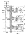
- the invention relates to figure 3 ) a remote reading device of the type of those which comprise a communication network 1, a central controller 2 connected to the network of communication 1, and a plurality of peripherals, such as 31 to 33, connected to the controller 2 via the network 1.
- each of the peripherals 31 to 33 takes, from among a set of states that are a priori possible, an instantaneous state STAT_1, STAT_2, and STAT_3, respectively, for the various devices 31 to 33, the controller 2 periodically scanning these peripherals 31 to 33. 33 to find the respective instantaneous states.
- the device of the invention differs first of all from known devices of this type in that the communication network 1 connects the peripherals, such as 31 to 33, to the controller 2 by electromagnetic means, and that the peripherals are powered. in electrical energy through this communication network 1.
- the mere presence of the communication network eliminates both the need to provide a separate power supply network, and the need to ensure the point-to-point electrical connection of each device.
- the communication network 1 comprises a series circuit which is itself powered by the controller 2 and which includes a plurality of electromagnetic induction loops such as 11, 12, and 13 ( figures 2 and 3 ), the electrical power signal flowing in this series circuit having a frequency typically less than 500 kHz, and being for example modulated at 125 kHz.
- Each device 31, 32, or 33 is furthermore equipped with a state encoder 61, 62, or 63 and a transmission and reception circuit 421, 422, or 423, the state encoder 61 , 62, or 63 being able to produce the instantaneous state STAT_1, STAT_2, or STAT_3 of this peripheral, and being connected to the transmission and reception circuit 421, 422, or 423 of this peripheral so as to enable it to transmit this state STAT_1, STAT_2, or STAT_3 to controller 2.
- each of the peripherals 31 to 33 can form a control terminal in the network 1, able to transmit to the controller 2 an order coded by the instantaneous state that adopts this device.
- each of the peripherals such as 31 to 33 also has an identification code of its own, and which is respectively noted KID_1 , KID_2, and KID_3 for the different devices 31 to 33.
- each device 31 to 33 preferably comprises an electronic tag such as 4 ( figure 1 ).
- An electronic tag is typically provided with a memory such as 411, a local antenna such as 401, and a transmission and reception circuit, such as 421, the latter being in this case likely to constitute the above-mentioned transmitting and receiving circuit of the device equipped with this tag.
- the labels of the different peripherals 31, 32 and 33 thus comprise, respectively, figure 3 ) memories 411, 412, and 413, local antennas 401, 402, and 403, and transmit and receive circuits 421, 422, and 423.
- Each memory 411, 412, or 413 contains the identification code KID_1, KID_2, or KID_3 assigned to the corresponding device, 31, 32, or 33.
- Each local antenna 401, 402, or 403 is coupled to one of the induction loops 11, 12, or 13 of the communication network 1 to receive the electrical energy transmitted by this induction loop.
- each transmission and reception circuit 421, 422, or 423 is connected to the corresponding local antenna 401, 402, or 403 to be able to receive from the corresponding induction loop the electrical energy required for power supply. of the device concerned, receive from the controller 2 a transmission order, and transmit to this controller 2 the instantaneous state STAT_1, STAT_2, or STAT_3 of the corresponding device, 31, 32, or 33, and the identification code KID_1, KID_2 , or KID_3 of the relevant label, in the advanced embodiment of the invention.
- each state encoder comprises two set members formed by manually operated electrical contacts by a user, namely the contacts 611 and 612 for the state encoder 61, 621 and 622 for the state encoder 62, and 631, 632 for state encoder 63.
- each state encoder could comprise, in addition to or instead of such deposit devices, a or more sensors that are sensitive to the influence of one or more physical parameters to which that device is subjected.
- Each device 31, 32, or 33 is provided with a processing unit 51, 52, or 53, external or internal to the electronic tag equipping this device, connected to the transmission and reception circuit 421, 422, or 423 of this device, and responsible for collecting, encoding and / or formatting the instantaneous state STAT_1, STAT_2, or STAT_3 for the consideration of this state by the transmitting and receiving circuit.
- a processing unit 51, 52, or 53 external or internal to the electronic tag equipping this device, connected to the transmission and reception circuit 421, 422, or 423 of this device, and responsible for collecting, encoding and / or formatting the instantaneous state STAT_1, STAT_2, or STAT_3 for the consideration of this state by the transmitting and receiving circuit.
- the controller 2 is provided with a configuration memory 21 in which are stored, for each peripheral 31, 32, or 33, the identification code KID_1, KID_2, or KID_3 of this device, and a location parameter, such as LOC_1, LOC_2, or LOC_3, which identifies the location of this device in the network 1, the location parameter of each device being correlated, that is to say, associated with the identification code of the same device.
- a configuration memory 21 in which are stored, for each peripheral 31, 32, or 33, the identification code KID_1, KID_2, or KID_3 of this device, and a location parameter, such as LOC_1, LOC_2, or LOC_3, which identifies the location of this device in the network 1, the location parameter of each device being correlated, that is to say, associated with the identification code of the same device.
- the association, in the configuration memory 21 of the controller 2, of the location parameter of each device with the identification code of the same device can be achieved, by the implementation of means known per se, during a phase of installation of the device of the invention.
- the controller 2 can therefore, by noting both the instant state STAT_1, STAT_2, or STAT_3 and the identification code KID_1, KID_2, or KID_3 of each peripheral 31, 32, or 33 that it scans, associating each of the instantaneous states recorded at a determined location of the network 1.
- each of the peripherals 31 to 33 can form a call terminal in the network 1, the controller 2 assuring the management of calls launched remotely via these devices or terminals 31 to 33.
- the Figures 3 to 5 illustrate an application of the device of the invention to the management of an elevator.
- the communication network 1 to which the controller 2 is connected comprises induction loops such as 11, 12 and 13 regularly arranged on one side of the vertical partition CL which closes the front face of the column.
- elevator for example on the right side of each elevator door, PT_1, PT_2, and PT_3.
- the peripherals 31, 32, and 33 are arranged on the other side of the partition CL, at the corresponding different stages, ETG_1, ETG_2, and ETG_3.
- these devices can for example be simply glued to the CL bulkhead near the corresponding PT_1, PT_2, or PT_3 door.
- the location parameters, such as LOC_1, LOC_2, and LOC_3 stored in the configuration memory 21 of the controller 2 are representative of the different stages, the identification code KID_1 of the device 31 being thus associated with the location parameter ETG_1 , representative of the first stage where this device is installed, the identification code KID_2 of the device 32 being associated with the location parameter ETG_2, representative of the second stage where this device is installed, etc.
- the controller 2 comprises a transmission and reception circuit 22 responsible for ensuring the transmission of electrical energy and the transmission of information on the network 1, a processing unit 23 ensuring set of information processing in this controller and having read and write access to the configuration memory 21, and an interface 24 driven by the processing unit 23 and ensuring the connection between the processing unit 23 and a control circuit 8 of the elevator.
- Each of the peripherals 31, 32, and 33 has an electrical contact 611, 621, and 631, which the user can control by a button to indicate his desire to descend to a lower stage, and an electrical contact 612, 622, and 632, that the user can command by a button to indicate his desire to go upstairs.
- the controller 2 will receive from this device the identification code KID_2, and the state STAT_2 of the state encoder 62, this state STAT_2 being representative of the actuation of the button of the contact 622.
- the controller 2 By reading its memory 21, the controller 2 will be informed that a user, located on the floor ETG_2, that is to say on the second floor, called the elevator, expressing more precisely his wish to access to an upper floor.
- This call can therefore be transmitted, via the interface 24 of the controller, to the control circuit 8 of the elevator, which will be responsible for bringing to the second floor the most accessible elevator car to get to an upper floor.
- each of the peripherals could have only one button, whose actuation would then be taken into account as a lift call for a destination a priori any, the user indicating its destination only one once installed in the elevator car, by pressing the button of the desired floor.
- each of the peripherals 31, 32, or 33 instead of having only one call button for access to an upper floor, and a call button for access to a lower floor, could having, as a state encoder 61, 62, or 63, a keyboard on which the user could specifically indicate his destination stage, which is to say that the state STAT_1, STAT_2 or STAT_3 of each
- the state encoder may be represented by any number of bits.
- each device such as 31, 32, or 33 may further comprise a display member such as 71, 72 or 73, this member being connected to the processing unit 51, 52, or 53, which retransmits the instructions display received from the controller 2 by the transmitting and receiving circuit 421, 422, or 423.
- a display member such as 71, 72 or 73, this member being connected to the processing unit 51, 52, or 53, which retransmits the instructions display received from the controller 2 by the transmitting and receiving circuit 421, 422, or 423.
- This display member 71, 72 or 73 makes it possible to make available, at the location of each of the peripherals, relevant information for all of these peripherals, such as the instantaneous direction of movement of the elevator car, or the number of the floor reached by this cabin.
- the partition CL of the illustrated embodiment serves the function of a support for the peripherals 31 to 33 and that of a dielectric separating the loops. induction 11 to 13 antennas 401 to 403.
- the wallpaper lining the walls of a room could both contain or cover a network of induction loops running through these walls, and serve as a support for a plurality of peripherals, taking for example the form of simple glued labels on its surface and making it possible to remotely control, selectively, lighting or respective electrical equipment distributed throughout the room.
- the fabric of a garment such as a jacket, could be traversed by a network of induction loops and serve as a support for a control member for electrical equipment, such as a magnetic tape drive or CD-ROM housed in the collar of this garment, this control member being for example applied to the garment by means of a simple velcro.
Landscapes
- Engineering & Computer Science (AREA)
- Automation & Control Theory (AREA)
- Selective Calling Equipment (AREA)
- Indicating And Signalling Devices For Elevators (AREA)
- Near-Field Transmission Systems (AREA)
- Elevator Control (AREA)
- Mobile Radio Communication Systems (AREA)
Claims (12)
- System zum Fernablesen von Zuständen, das ein Kommunikationsnetz (1), eine mit dem Kommunikationsnetz (1) verbundene zentrale Steuereinheit (2) und eine Vielzahl von über das Netz (1) mit der Steuereinheit (2) verbundenen Peripheriegeräten (31 bis 33) enthält, wobei jedes Peripheriegerät (31 bis 33) zu jedem Zeitpunkt einen Augenblickszustand (STAT_1 bis STAT_3) annimmt, der zu einer Vielzahl möglicher Zustände gehört, und die Steuereinheit (2) periodisch die Peripheriegeräte (31 bis 33) prüft, um ihren Augenblickszustand (STAT_1 bis STAT_3) abzulesen, wobei das Kommunikationsnetz (1) die Peripheriegeräte (31 bis 33) elektromagnetisch mit der Steuereinheit (2) verbindet, und die Peripheriegeräte (31 bis 33) über dieses Kommunikationsnetz (1) mit elektrischer Energie versorgt werden, dadurch gekennzeichnet, dass jedes Peripheriegerät (31 bis 33) eine lokale Antenne (401, 402, 403) enthält, die mit einer Induktionsschleife (11, 12, 13) des Kommunikationsnetzes (1) gekoppelt ist, dass das Peripheriegerät (31 bis 33) über diese Schleife (11, 12, 13) mit elektrischer Energie versorgt wird, und dass die Induktionsschleife (11 bis 13) und die Antenne (401, 402, 403) durch einen Träger getrennt sind, und dass die Peripheriegeräte durch den Träger hindurch mit elektrischer Energie versorgt werden, wobei dieser Träger von einer Trennwand (CL) gebildet wird.
- System zum Fernablesen von Zuständen nach Anspruch 1, dadurch gekennzeichnet, dass das Kommunikationsnetz (1) eine serielle Schaltung enthält, die von der Steuereinheit (2) versorgt wird und eine Vielzahl von elektromagnetischen Induktionsschleifen (11, 12, 13) umfasst.
- System zum Fernablesen von Zuständen nach den Ansprüchen 1 oder 2, dadurch gekennzeichnet, dass jedes Peripheriegerät (31 bis 33) über einen ihm eigenen Identifikationscode (KID_1 bis KID_3) verfügt, dass die Steuereinheit (2) über einen Konfigurationsspeicher (21) verfügt, in dem für ein Peripheriegerät (31 bis 33) der Identifikationscode (KID_1 bis KID_3) dieses Peripheriegeräts und ein Lokalisierungsparameter (LOC_1 bis LOC_3) korreliert gespeichert sind, der den Standort dieses Peripheriegeräts (31 bis 33) im Netz (1) kennzeichnet, und dass die Steuereinheit (2) für jedes Peripheriegerät (31 bis 33) den Augenblickszustand (STAT_1 bis STAT_3) dieses Peripheriegeräts (31 bis 33) und seinen Identifikationscode (KID_1 bis KID_3) abliest, woraus sich ergibt, dass jeder abgelesene Augenblickszustand (STAT_1 bis STAT_3) von der Steuereinheit (2) mit einem Standort des Netzes (1) korreliert wird.
- System zum Fernablesen von Zuständen nach den Ansprüchen 1 bis 3, dadurch gekennzeichnet, dass jedes Peripheriegerät (31 bis 33) außerdem eine Sende- und Empfangsschaltung (421, 422, 423) enthält, wobei mindestens ein Zustandscodierer (61, 62, 63) einen Augenblickszustand (STAT_1 bis STAT_3) annimmt, der den Augenblickszustand dieses Peripheriegeräts bildet oder zu seinem Aufbau beiträgt, wobei dieser Zustandscodierer (61, 62, 63) mit der Sende- und Empfangsschaltung (421, 422, 423) verbunden ist, um es diesem Peripheriegerät (31 bis 33) zu erlauben, den Augenblickszustand (STAT_1 bis STAT_3) des Codierers (61, 62, 63) an die Steuereinheit (2) zu übertragen.
- System zum Fernablesen von Zuständen nach den Ansprüchen 2 bis 4, dadurch gekennzeichnet, dass jedes Peripheriegerät (31 bis 33) ein elektronisches Etikett (4) enthält, das mit einem Speicher (411, 412, 413), der den diesem Peripheriegerät (31 bis 33) zugeteilten Identifikationscode (KID_1 bis KID_3) enthält, einer lokalen Antenne (401, 402; 403), die mit einer Induktionsschleife (11, 12, 13) des Kommunikationsnetzes (1) gekoppelt ist, um die von dieser Induktionsschleife übertragene elektrische Energie zu empfangen, und mit der Sende- und Empfangsschaltung (421, 422, 423) ausgestattet ist, wobei diese Sende- und Empfangsschaltung mit der lokalen Antenne (401, 402, 403) verbunden ist, um mindestens von der Steuereinheit (2) einen Übertragungsbefehl zu empfangen, und um an die Steuereinheit (2) außer dem Augenblickszustand (STAT_1 bis STAT_3) des Codierers (61, 62, 63) den Identifikationscode (KID_1 bis KID_3) dieses Etiketts zu übertragen.
- System zum Fernablesen von Zuständen nach Anspruch 4 oder 5, dadurch gekennzeichnet, dass jedes Peripheriegerät (31 bis 33) als Zustandscodierer (61, 62, 63) mindestens ein Zuweisungsorgan (611, 621, 631) wie einen elektrischen Kontakt enthält.
- System zum Fernablesen von Zuständen nach einem der Ansprüche 4 bis 6, dadurch gekennzeichnet, dass jedes Peripheriegerät (31 bis 33) als Zustandscodierer mindestens einen Sensor enthält, der auf den Einfluss eines physikalischen Parameters anspricht, dem dieses Peripheriegeräte ausgesetzt ist.
- System zum Fernablesen von Zuständen nach einem der Ansprüche 4 bis 7, dadurch gekennzeichnet, dass jedes Peripheriegerät (31 bis 33) außerdem ein Anzeigeorgan (71, 72, 73) enthält.
- System zum Fernablesen von Zuständen nach einem der vorhergehenden Ansprüche, dadurch gekennzeichnet, dass jedes Peripheriegerät (31 bis 33) einen Steueranschluss für die Verwaltung von Fernsteuerungen formt.
- System zum Fernablesen von Zuständen nach einem der Ansprüche 1 bis 8, dadurch gekennzeichnet, dass jedes Peripheriegerät (31 bis 33) einen Anrufanschluss für die Verwaltung von Fernanrufen formt.
- System zum Fernablesen von Zuständen nach Anspruch 10, dadurch gekennzeichnet, dass jedes Peripheriegerät (31 bis 33) an einem spezifischen Standort wie einer Etage (ETG_1 bis ETG_3) eines Gebäudes installiert ist und einen Anrufanschluss für eine Transporteinrichtung wie einen Aufzug formt.
- System zum Fernablesen von Zuständen nach Anspruch 11, dadurch gekennzeichnet, dass der Zustandsco-dierer jedes Peripheriegeräts (31 bis 33) eine Vielzahl von Zuweisungsorganen (611, 612; 621, 622; 631, 632) wie elektrische Kontakte aufweist, von denen jedes einen der Transporteinrichtung zugewiesenen Zielort ausgehend von einer Ausgangsstellung kennzeichnet, die durch den spezifischen Standort dargestellt wird.
Applications Claiming Priority (3)
| Application Number | Priority Date | Filing Date | Title |
|---|---|---|---|
| FR0207295A FR2841084B1 (fr) | 2002-06-13 | 2002-06-13 | Dispositif de telereleve d'etats, et applications |
| FR0207295 | 2002-06-13 | ||
| PCT/EP2003/007129 WO2003107295A2 (fr) | 2002-06-13 | 2003-06-12 | Dispositif de telereleve d’etats, et applications |
Publications (2)
| Publication Number | Publication Date |
|---|---|
| EP1511684A2 EP1511684A2 (de) | 2005-03-09 |
| EP1511684B1 true EP1511684B1 (de) | 2013-10-23 |
Family
ID=29595214
Family Applications (1)
| Application Number | Title | Priority Date | Filing Date |
|---|---|---|---|
| EP03738114.2A Expired - Lifetime EP1511684B1 (de) | 2002-06-13 | 2003-06-12 | Anordnung zur fernablesung der zustände und anwendungen hierfür |
Country Status (8)
| Country | Link |
|---|---|
| US (1) | US8145744B2 (de) |
| EP (1) | EP1511684B1 (de) |
| JP (1) | JP2005536083A (de) |
| CN (1) | CN1659095B (de) |
| CA (1) | CA2487525C (de) |
| FR (1) | FR2841084B1 (de) |
| NZ (1) | NZ537059A (de) |
| WO (1) | WO2003107295A2 (de) |
Cited By (1)
| Publication number | Priority date | Publication date | Assignee | Title |
|---|---|---|---|---|
| DE112014006714B4 (de) | 2014-05-30 | 2019-12-24 | Mitsubishi Electric Corporation | Aufzugspositions-erfassungsvorrichtung |
Families Citing this family (13)
| Publication number | Priority date | Publication date | Assignee | Title |
|---|---|---|---|---|
| CN101746656B (zh) * | 2008-12-16 | 2014-06-11 | 中国建筑科学研究院建筑机械化研究分院 | 电梯再生电能利用系统 |
| RU2524319C2 (ru) | 2009-02-25 | 2014-07-27 | Инвенцио Аг | Лифт с системой контроля |
| IT1397103B1 (it) | 2009-11-23 | 2012-12-28 | Stem Srl | Procedimento di rilevamento della posizione di apparecchi in movimento, quali ascensori e simili, e relativo dispositivo |
| EP2527190B1 (de) * | 2010-01-22 | 2017-06-07 | Hitachi Construction Machinery Co., Ltd. | Elektrisch betriebenes fahrzeug |
| US20120203620A1 (en) | 2010-11-08 | 2012-08-09 | Douglas Howard Dobyns | Techniques For Wireless Communication Of Proximity Based Marketing |
| US8929809B2 (en) | 2011-03-22 | 2015-01-06 | Radeum, Inc. | Techniques for wireless communication of proximity based content |
| US8880100B2 (en) | 2011-03-23 | 2014-11-04 | Radium, Inc. | Proximity based social networking |
| US9705564B2 (en) | 2014-08-29 | 2017-07-11 | Freelinc Technologies | Spatially enabled secure communications |
| JP2016060617A (ja) * | 2014-09-19 | 2016-04-25 | 株式会社日立ビルシステム | テールコードレスエレベータの電力供給装置 |
| US10164685B2 (en) | 2014-12-31 | 2018-12-25 | Freelinc Technologies Inc. | Spatially aware wireless network |
| WO2016126919A1 (en) * | 2015-02-05 | 2016-08-11 | Otis Elevator Company | Multi-car elevator control |
| AU2016376176B2 (en) | 2015-12-21 | 2019-10-03 | Inventio Ag | Monitoring device for a passenger transport system, testing method and passenger transport system |
| CN110980451B (zh) * | 2019-11-08 | 2022-07-15 | 苏州汇川技术有限公司 | 电梯错层快速矫正方法、系统、设备及存储介质 |
Family Cites Families (43)
| Publication number | Priority date | Publication date | Assignee | Title |
|---|---|---|---|---|
| US1715701A (en) * | 1929-06-04 | Inghottse electric | ||
| US1526306A (en) * | 1924-04-19 | 1925-02-10 | Gen Electric | Damping mechanism for instruments |
| US4193478A (en) * | 1977-04-26 | 1980-03-18 | Elevator Industries | Elevator control system and method |
| US4252217A (en) * | 1978-02-28 | 1981-02-24 | Litton Systems, Inc. | Semi-automated warehousing system |
| CH644820A5 (de) | 1978-12-12 | 1984-08-31 | Inventio Ag | Aufzugsanlage. |
| ATE86939T1 (de) * | 1986-04-03 | 1993-04-15 | Otis Elevator Co | Zweirichtungsringverbindungssystem fuer aufzugsgruppensteuerung. |
| JPS6369335A (ja) * | 1986-09-11 | 1988-03-29 | Nippon Denzai Kogyo Kenkyusho:Kk | 非接触伝送装置 |
| US4879756A (en) | 1986-09-22 | 1989-11-07 | Stevens John K | Radio broadcast communication systems |
| US4937586A (en) | 1986-09-22 | 1990-06-26 | Stevens John K | Radio broadcast communication systems with multiple loop antennas |
| US4821291A (en) | 1986-09-22 | 1989-04-11 | Stevens John K | Improvements in or relating to signal communication systems |
| GB2208731B (en) * | 1987-08-12 | 1991-10-16 | Hitachi Ltd | Signal transmission method and system in elevator equipment |
| JPH0620985B2 (ja) * | 1987-08-12 | 1994-03-23 | 株式会社日立製作所 | エレベーターの信号伝送方法及びエレベーター装置 |
| JPS6460586A (en) * | 1987-08-26 | 1989-03-07 | Mitsubishi Electric Corp | Controller for elevator |
| US5274203A (en) * | 1989-06-30 | 1993-12-28 | Otis Elevator Company | "Smart" position transducer system for elevators |
| US5028918A (en) | 1989-12-18 | 1991-07-02 | Dairy Equipment Company | Identification transponder circuit |
| US5260701A (en) * | 1990-01-19 | 1993-11-09 | Societe Bertin & Cie | Bidirectional inductive transmission of data with slave station supplied by the master |
| JP3278200B2 (ja) * | 1992-06-23 | 2002-04-30 | 三菱電機株式会社 | エレベータのデータ伝送装置 |
| US5535212A (en) * | 1992-12-21 | 1996-07-09 | Otis Elevator Company | Implicit token media access protocol without collision detection |
| US5532465A (en) * | 1993-03-15 | 1996-07-02 | Electronic Retailing Systems International, Inc. | Technique for locating electronic labels in an electronic price display system |
| US5850416A (en) * | 1993-06-30 | 1998-12-15 | Lucent Technologies, Inc. | Wireless transmitter-receiver information device |
| US5793360A (en) | 1995-05-05 | 1998-08-11 | Wacom Co., Ltd. | Digitizer eraser system and method |
| US5975248A (en) * | 1995-08-11 | 1999-11-02 | Drucegrove Limited | Communications system |
| US5732795A (en) * | 1996-04-10 | 1998-03-31 | Otis Elevator Company | Power and communication for elevator car without traveling cable |
| US6209480B1 (en) * | 1996-07-10 | 2001-04-03 | Mehrdad M. Moslehi | Hermetically-sealed inductively-coupled plasma source structure and method of use |
| US5854454A (en) * | 1996-09-16 | 1998-12-29 | Otis Elevator Company | Message routing in control area network (CAN) protocol |
| NZ501864A (en) | 1997-06-12 | 2002-08-28 | Auckland Uniservices Ltd | Apparatus and method for transferring information or data in a wireless manner from point to point along the route of an inductively powered pathway |
| TW475919B (en) * | 1997-08-20 | 2002-02-11 | Lg Otis Elevator Co | An elevator control system |
| US6084513A (en) * | 1997-09-26 | 2000-07-04 | Innovative Control Systems | Method and apparatus for tracking a patient |
| JP3792913B2 (ja) * | 1997-11-17 | 2006-07-05 | 株式会社東芝 | 保守点検支援装置 |
| US6163270A (en) * | 1998-03-23 | 2000-12-19 | At&T Corp. | Apparatus and method for controlling communication in an electronic control and monitoring system |
| SG97809A1 (en) * | 1998-09-17 | 2003-08-20 | Inventio Ag | Remote control of lift installations |
| US5984051A (en) * | 1998-11-09 | 1999-11-16 | Otis Elevator Company | Remote elevator call requests with descriptor tags |
| JP2000150174A (ja) * | 1998-11-16 | 2000-05-30 | Hitachi Ltd | 空港灯火制御装置 |
| JP3857457B2 (ja) * | 1999-03-02 | 2006-12-13 | 株式会社東芝 | 灯火監視制御システム |
| WO2001002211A1 (en) | 1999-07-02 | 2001-01-11 | Magnemotion, Inc. | System for inductive transfer of power, communication and position sensing to a guideway-operated vehicle |
| JP3864647B2 (ja) * | 1999-11-26 | 2007-01-10 | 株式会社日立製作所 | エレベータシステム |
| US6774764B2 (en) * | 2000-02-25 | 2004-08-10 | Delphi Technologies, Inc. | Securing system for motor vehicle |
| US6341668B1 (en) * | 2000-04-03 | 2002-01-29 | Televator One, Llc | Interactive elevator communication system |
| AU7953101A (en) * | 2000-08-07 | 2002-02-18 | Inventio Ag | Monitoring device for an elevator |
| EP2461344A3 (de) * | 2000-11-21 | 2014-10-15 | Bradbury R. Face | Selbstangetriebenes lehrbares Schaltnetzwerk |
| US6601679B2 (en) * | 2001-09-05 | 2003-08-05 | Otis Elevator Company | Two-part wireless communications system for elevator hallway fixtures |
| US6554107B2 (en) * | 2001-09-27 | 2003-04-29 | Mitsubishi Denki Kabushiki Kaisha | Elevator system |
| US20030191730A1 (en) * | 2002-04-05 | 2003-10-09 | Compaq Information Technologies Group, L.P. | Unobtrusive rule-based computer usage enhancement system |
-
2002
- 2002-06-13 FR FR0207295A patent/FR2841084B1/fr not_active Expired - Fee Related
-
2003
- 2003-06-12 JP JP2004514032A patent/JP2005536083A/ja active Pending
- 2003-06-12 CA CA2487525A patent/CA2487525C/en not_active Expired - Fee Related
- 2003-06-12 WO PCT/EP2003/007129 patent/WO2003107295A2/fr not_active Ceased
- 2003-06-12 CN CN038136325A patent/CN1659095B/zh not_active Expired - Fee Related
- 2003-06-12 US US10/517,797 patent/US8145744B2/en not_active Expired - Fee Related
- 2003-06-12 NZ NZ537059A patent/NZ537059A/en not_active IP Right Cessation
- 2003-06-12 EP EP03738114.2A patent/EP1511684B1/de not_active Expired - Lifetime
Cited By (1)
| Publication number | Priority date | Publication date | Assignee | Title |
|---|---|---|---|---|
| DE112014006714B4 (de) | 2014-05-30 | 2019-12-24 | Mitsubishi Electric Corporation | Aufzugspositions-erfassungsvorrichtung |
Also Published As
| Publication number | Publication date |
|---|---|
| CA2487525A1 (en) | 2003-12-24 |
| HK1074827A1 (en) | 2005-11-25 |
| CN1659095B (zh) | 2013-01-30 |
| AU2003244639A1 (en) | 2003-12-31 |
| JP2005536083A (ja) | 2005-11-24 |
| US20060077033A1 (en) | 2006-04-13 |
| CA2487525C (en) | 2012-09-25 |
| NZ537059A (en) | 2006-11-30 |
| WO2003107295A3 (fr) | 2004-03-18 |
| CN1659095A (zh) | 2005-08-24 |
| WO2003107295A2 (fr) | 2003-12-24 |
| FR2841084A1 (fr) | 2003-12-19 |
| FR2841084B1 (fr) | 2004-12-17 |
| EP1511684A2 (de) | 2005-03-09 |
| US8145744B2 (en) | 2012-03-27 |
Similar Documents
| Publication | Publication Date | Title |
|---|---|---|
| EP1511684B1 (de) | Anordnung zur fernablesung der zustände und anwendungen hierfür | |
| EP2341469B1 (de) | Elektronisches System und Verfahren zum Management von konkurrierenden kontaktlosen Kommunikationen im System | |
| EP0722157B1 (de) | System zur Sicherung von Gegenständen gegen Diebstahl | |
| US10322761B2 (en) | Pile-free parking management system and method | |
| EP2633372B1 (de) | Verfahren zum betrieb einer domotikanlage | |
| FR2806568A1 (fr) | Procede pour generer des donnees d'identification et d'authentification | |
| US9082244B2 (en) | Method of controlling access to an area | |
| EP2633506A1 (de) | Verfahren für den betrieb einer mobilen steuereinheit einer domotikanlage | |
| EP2333704B1 (de) | Mikrochipkartenkörper, der als Träger für zwei elektronische Etiketten fungiert | |
| EP2633507A1 (de) | Verfahren für den betrieb einer mobilen steuereinheit einer domotikanlage | |
| FI115551B (fi) | Lukitusjärjestelmä ja menetelmä lukitusjärjestelmää varten | |
| EP2793197B1 (de) | Verfahren und automatisches System zur Zugangskontrolle | |
| FR2942755A1 (fr) | Procede d'identification d'un individu en vue d'autoriser une action commandee par un organe d'actionnement | |
| EP1514222B1 (de) | Steuer- und/oder überwachungseinrichtung mit einem elektronischen label und leser und zustandscodierer | |
| EP4040410B1 (de) | Zugangskontrollsystem für gebäude | |
| EP2419865B1 (de) | Kommunikationsvorrichtung mit zwei über eine gemeinsame kommunikationsschnittstelle verbundenen chips | |
| JP4422495B2 (ja) | 建物用ドア錠制御装置 | |
| JP4443866B2 (ja) | 通知装置 | |
| CA2297797A1 (fr) | Objet portatif a communication sans contact suivant deux voies de communication, inductive et hertzienne | |
| CN1964535B (zh) | 终端代理登场决定方法及装置 | |
| JP5100697B2 (ja) | 通知装置の通知方法、通知装置、通知システム | |
| EP1514162A1 (de) | Steuer- und/oder überwachungseinrichtung mit mindestens einer übertragungssteuerung | |
| EP4478691B1 (de) | Gegensprechanlage | |
| JP6993039B1 (ja) | ドア掛け式ロック | |
| JP2009295110A (ja) | 記録装置及び記録媒体 |
Legal Events
| Date | Code | Title | Description |
|---|---|---|---|
| PUAI | Public reference made under article 153(3) epc to a published international application that has entered the european phase |
Free format text: ORIGINAL CODE: 0009012 |
|
| 17P | Request for examination filed |
Effective date: 20041217 |
|
| AK | Designated contracting states |
Kind code of ref document: A2 Designated state(s): AT BE BG CH CY CZ DE DK EE ES FI FR GB GR HU IE IT LI LU MC NL PT RO SE SI SK TR |
|
| AX | Request for extension of the european patent |
Extension state: AL LT LV MK |
|
| DAX | Request for extension of the european patent (deleted) | ||
| REG | Reference to a national code |
Ref country code: HK Ref legal event code: DE Ref document number: 1074827 Country of ref document: HK |
|
| RIN1 | Information on inventor provided before grant (corrected) |
Inventor name: GIELIS, MICHEL |
|
| 17Q | First examination report despatched |
Effective date: 20071116 |
|
| GRAP | Despatch of communication of intention to grant a patent |
Free format text: ORIGINAL CODE: EPIDOSNIGR1 |
|
| INTG | Intention to grant announced |
Effective date: 20130802 |
|
| GRAS | Grant fee paid |
Free format text: ORIGINAL CODE: EPIDOSNIGR3 |
|
| GRAA | (expected) grant |
Free format text: ORIGINAL CODE: 0009210 |
|
| AK | Designated contracting states |
Kind code of ref document: B1 Designated state(s): AT BE BG CH CY CZ DE DK EE ES FI FR GB GR HU IE IT LI LU MC NL PT RO SE SI SK TR |
|
| REG | Reference to a national code |
Ref country code: GB Ref legal event code: FG4D Free format text: NOT ENGLISH |
|
| REG | Reference to a national code |
Ref country code: CH Ref legal event code: EP |
|
| REG | Reference to a national code |
Ref country code: AT Ref legal event code: REF Ref document number: 637463 Country of ref document: AT Kind code of ref document: T Effective date: 20131115 |
|
| REG | Reference to a national code |
Ref country code: IE Ref legal event code: FG4D Free format text: LANGUAGE OF EP DOCUMENT: FRENCH |
|
| REG | Reference to a national code |
Ref country code: DE Ref legal event code: R096 Ref document number: 60345146 Country of ref document: DE Effective date: 20131219 |
|
| REG | Reference to a national code |
Ref country code: NL Ref legal event code: VDEP Effective date: 20131023 |
|
| REG | Reference to a national code |
Ref country code: AT Ref legal event code: MK05 Ref document number: 637463 Country of ref document: AT Kind code of ref document: T Effective date: 20131023 |
|
| PG25 | Lapsed in a contracting state [announced via postgrant information from national office to epo] |
Ref country code: SE Free format text: LAPSE BECAUSE OF FAILURE TO SUBMIT A TRANSLATION OF THE DESCRIPTION OR TO PAY THE FEE WITHIN THE PRESCRIBED TIME-LIMIT Effective date: 20131023 Ref country code: NL Free format text: LAPSE BECAUSE OF FAILURE TO SUBMIT A TRANSLATION OF THE DESCRIPTION OR TO PAY THE FEE WITHIN THE PRESCRIBED TIME-LIMIT Effective date: 20131023 Ref country code: FI Free format text: LAPSE BECAUSE OF FAILURE TO SUBMIT A TRANSLATION OF THE DESCRIPTION OR TO PAY THE FEE WITHIN THE PRESCRIBED TIME-LIMIT Effective date: 20131023 |
|
| PG25 | Lapsed in a contracting state [announced via postgrant information from national office to epo] |
Ref country code: CY Free format text: LAPSE BECAUSE OF FAILURE TO SUBMIT A TRANSLATION OF THE DESCRIPTION OR TO PAY THE FEE WITHIN THE PRESCRIBED TIME-LIMIT Effective date: 20131023 Ref country code: AT Free format text: LAPSE BECAUSE OF FAILURE TO SUBMIT A TRANSLATION OF THE DESCRIPTION OR TO PAY THE FEE WITHIN THE PRESCRIBED TIME-LIMIT Effective date: 20131023 Ref country code: ES Free format text: LAPSE BECAUSE OF FAILURE TO SUBMIT A TRANSLATION OF THE DESCRIPTION OR TO PAY THE FEE WITHIN THE PRESCRIBED TIME-LIMIT Effective date: 20131023 |
|
| REG | Reference to a national code |
Ref country code: HK Ref legal event code: GR Ref document number: 1074827 Country of ref document: HK |
|
| PG25 | Lapsed in a contracting state [announced via postgrant information from national office to epo] |
Ref country code: PT Free format text: LAPSE BECAUSE OF FAILURE TO SUBMIT A TRANSLATION OF THE DESCRIPTION OR TO PAY THE FEE WITHIN THE PRESCRIBED TIME-LIMIT Effective date: 20140224 |
|
| REG | Reference to a national code |
Ref country code: DE Ref legal event code: R097 Ref document number: 60345146 Country of ref document: DE |
|
| PG25 | Lapsed in a contracting state [announced via postgrant information from national office to epo] |
Ref country code: EE Free format text: LAPSE BECAUSE OF FAILURE TO SUBMIT A TRANSLATION OF THE DESCRIPTION OR TO PAY THE FEE WITHIN THE PRESCRIBED TIME-LIMIT Effective date: 20131023 |
|
| PG25 | Lapsed in a contracting state [announced via postgrant information from national office to epo] |
Ref country code: SK Free format text: LAPSE BECAUSE OF FAILURE TO SUBMIT A TRANSLATION OF THE DESCRIPTION OR TO PAY THE FEE WITHIN THE PRESCRIBED TIME-LIMIT Effective date: 20131023 Ref country code: CZ Free format text: LAPSE BECAUSE OF FAILURE TO SUBMIT A TRANSLATION OF THE DESCRIPTION OR TO PAY THE FEE WITHIN THE PRESCRIBED TIME-LIMIT Effective date: 20131023 Ref country code: RO Free format text: LAPSE BECAUSE OF FAILURE TO SUBMIT A TRANSLATION OF THE DESCRIPTION OR TO PAY THE FEE WITHIN THE PRESCRIBED TIME-LIMIT Effective date: 20131023 Ref country code: IT Free format text: LAPSE BECAUSE OF FAILURE TO SUBMIT A TRANSLATION OF THE DESCRIPTION OR TO PAY THE FEE WITHIN THE PRESCRIBED TIME-LIMIT Effective date: 20131023 |
|
| PLBE | No opposition filed within time limit |
Free format text: ORIGINAL CODE: 0009261 |
|
| STAA | Information on the status of an ep patent application or granted ep patent |
Free format text: STATUS: NO OPPOSITION FILED WITHIN TIME LIMIT |
|
| PG25 | Lapsed in a contracting state [announced via postgrant information from national office to epo] |
Ref country code: DK Free format text: LAPSE BECAUSE OF FAILURE TO SUBMIT A TRANSLATION OF THE DESCRIPTION OR TO PAY THE FEE WITHIN THE PRESCRIBED TIME-LIMIT Effective date: 20131023 |
|
| 26N | No opposition filed |
Effective date: 20140724 |
|
| REG | Reference to a national code |
Ref country code: DE Ref legal event code: R097 Ref document number: 60345146 Country of ref document: DE Effective date: 20140724 |
|
| PG25 | Lapsed in a contracting state [announced via postgrant information from national office to epo] |
Ref country code: MC Free format text: LAPSE BECAUSE OF FAILURE TO SUBMIT A TRANSLATION OF THE DESCRIPTION OR TO PAY THE FEE WITHIN THE PRESCRIBED TIME-LIMIT Effective date: 20131023 Ref country code: LU Free format text: LAPSE BECAUSE OF FAILURE TO SUBMIT A TRANSLATION OF THE DESCRIPTION OR TO PAY THE FEE WITHIN THE PRESCRIBED TIME-LIMIT Effective date: 20140612 |
|
| GBPC | Gb: european patent ceased through non-payment of renewal fee |
Effective date: 20140612 |
|
| PG25 | Lapsed in a contracting state [announced via postgrant information from national office to epo] |
Ref country code: SI Free format text: LAPSE BECAUSE OF FAILURE TO SUBMIT A TRANSLATION OF THE DESCRIPTION OR TO PAY THE FEE WITHIN THE PRESCRIBED TIME-LIMIT Effective date: 20131023 |
|
| REG | Reference to a national code |
Ref country code: IE Ref legal event code: MM4A |
|
| PG25 | Lapsed in a contracting state [announced via postgrant information from national office to epo] |
Ref country code: IE Free format text: LAPSE BECAUSE OF NON-PAYMENT OF DUE FEES Effective date: 20140612 |
|
| PG25 | Lapsed in a contracting state [announced via postgrant information from national office to epo] |
Ref country code: GB Free format text: LAPSE BECAUSE OF NON-PAYMENT OF DUE FEES Effective date: 20140612 |
|
| PG25 | Lapsed in a contracting state [announced via postgrant information from national office to epo] |
Ref country code: BG Free format text: LAPSE BECAUSE OF FAILURE TO SUBMIT A TRANSLATION OF THE DESCRIPTION OR TO PAY THE FEE WITHIN THE PRESCRIBED TIME-LIMIT Effective date: 20131023 |
|
| REG | Reference to a national code |
Ref country code: FR Ref legal event code: PLFP Year of fee payment: 14 |
|
| PG25 | Lapsed in a contracting state [announced via postgrant information from national office to epo] |
Ref country code: GR Free format text: LAPSE BECAUSE OF FAILURE TO SUBMIT A TRANSLATION OF THE DESCRIPTION OR TO PAY THE FEE WITHIN THE PRESCRIBED TIME-LIMIT Effective date: 20140124 |
|
| PG25 | Lapsed in a contracting state [announced via postgrant information from national office to epo] |
Ref country code: HU Free format text: LAPSE BECAUSE OF FAILURE TO SUBMIT A TRANSLATION OF THE DESCRIPTION OR TO PAY THE FEE WITHIN THE PRESCRIBED TIME-LIMIT; INVALID AB INITIO Effective date: 20030612 Ref country code: TR Free format text: LAPSE BECAUSE OF FAILURE TO SUBMIT A TRANSLATION OF THE DESCRIPTION OR TO PAY THE FEE WITHIN THE PRESCRIBED TIME-LIMIT Effective date: 20131023 Ref country code: BE Free format text: LAPSE BECAUSE OF FAILURE TO SUBMIT A TRANSLATION OF THE DESCRIPTION OR TO PAY THE FEE WITHIN THE PRESCRIBED TIME-LIMIT Effective date: 20140630 |
|
| REG | Reference to a national code |
Ref country code: FR Ref legal event code: PLFP Year of fee payment: 15 |
|
| REG | Reference to a national code |
Ref country code: FR Ref legal event code: PLFP Year of fee payment: 16 |
|
| PGFP | Annual fee paid to national office [announced via postgrant information from national office to epo] |
Ref country code: DE Payment date: 20190619 Year of fee payment: 17 |
|
| PGFP | Annual fee paid to national office [announced via postgrant information from national office to epo] |
Ref country code: FR Payment date: 20190619 Year of fee payment: 17 |
|
| PGFP | Annual fee paid to national office [announced via postgrant information from national office to epo] |
Ref country code: CH Payment date: 20190619 Year of fee payment: 17 |
|
| REG | Reference to a national code |
Ref country code: DE Ref legal event code: R119 Ref document number: 60345146 Country of ref document: DE |
|
| REG | Reference to a national code |
Ref country code: CH Ref legal event code: PL |
|
| PG25 | Lapsed in a contracting state [announced via postgrant information from national office to epo] |
Ref country code: FR Free format text: LAPSE BECAUSE OF NON-PAYMENT OF DUE FEES Effective date: 20200630 Ref country code: LI Free format text: LAPSE BECAUSE OF NON-PAYMENT OF DUE FEES Effective date: 20200630 Ref country code: CH Free format text: LAPSE BECAUSE OF NON-PAYMENT OF DUE FEES Effective date: 20200630 |
|
| PG25 | Lapsed in a contracting state [announced via postgrant information from national office to epo] |
Ref country code: DE Free format text: LAPSE BECAUSE OF NON-PAYMENT OF DUE FEES Effective date: 20210101 |