EP1511131B1 - Transformator, Lampensockel mit einem Transformator und Hochdruckentladungslampe - Google Patents
Transformator, Lampensockel mit einem Transformator und Hochdruckentladungslampe Download PDFInfo
- Publication number
- EP1511131B1 EP1511131B1 EP04017001A EP04017001A EP1511131B1 EP 1511131 B1 EP1511131 B1 EP 1511131B1 EP 04017001 A EP04017001 A EP 04017001A EP 04017001 A EP04017001 A EP 04017001A EP 1511131 B1 EP1511131 B1 EP 1511131B1
- Authority
- EP
- European Patent Office
- Prior art keywords
- transformer
- lamp base
- housing
- chamber
- guide
- Prior art date
- Legal status (The legal status is an assumption and is not a legal conclusion. Google has not performed a legal analysis and makes no representation as to the accuracy of the status listed.)
- Expired - Lifetime
Links
- 238000004804 winding Methods 0.000 claims abstract description 39
- 239000002184 metal Substances 0.000 claims description 19
- 230000037431 insertion Effects 0.000 claims description 5
- 238000003780 insertion Methods 0.000 claims description 5
- 125000006850 spacer group Chemical group 0.000 claims description 3
- 238000009423 ventilation Methods 0.000 claims 1
- 238000004519 manufacturing process Methods 0.000 description 6
- 150000001875 compounds Chemical class 0.000 description 5
- 238000009434 installation Methods 0.000 description 5
- 238000004382 potting Methods 0.000 description 5
- 229910000859 α-Fe Inorganic materials 0.000 description 3
- 238000002347 injection Methods 0.000 description 2
- 239000007924 injection Substances 0.000 description 2
- VYPSYNLAJGMNEJ-UHFFFAOYSA-N Silicium dioxide Chemical compound O=[Si]=O VYPSYNLAJGMNEJ-UHFFFAOYSA-N 0.000 description 1
- 239000003990 capacitor Substances 0.000 description 1
- 239000004020 conductor Substances 0.000 description 1
- 230000001419 dependent effect Effects 0.000 description 1
- 238000005538 encapsulation Methods 0.000 description 1
- 239000011521 glass Substances 0.000 description 1
- 238000005192 partition Methods 0.000 description 1
- 230000035515 penetration Effects 0.000 description 1
- 230000006641 stabilisation Effects 0.000 description 1
- 238000011105 stabilization Methods 0.000 description 1
- 229910001220 stainless steel Inorganic materials 0.000 description 1
- 239000010935 stainless steel Substances 0.000 description 1
- 238000003466 welding Methods 0.000 description 1
Images



Classifications
-
- H—ELECTRICITY
- H01—ELECTRIC ELEMENTS
- H01F—MAGNETS; INDUCTANCES; TRANSFORMERS; SELECTION OF MATERIALS FOR THEIR MAGNETIC PROPERTIES
- H01F27/00—Details of transformers or inductances, in general
- H01F27/02—Casings
-
- H—ELECTRICITY
- H05—ELECTRIC TECHNIQUES NOT OTHERWISE PROVIDED FOR
- H05B—ELECTRIC HEATING; ELECTRIC LIGHT SOURCES NOT OTHERWISE PROVIDED FOR; CIRCUIT ARRANGEMENTS FOR ELECTRIC LIGHT SOURCES, IN GENERAL
- H05B41/00—Circuit arrangements or apparatus for igniting or operating discharge lamps
- H05B41/02—Details
- H05B41/04—Starting switches
- H05B41/042—Starting switches using semiconductor devices
-
- H—ELECTRICITY
- H01—ELECTRIC ELEMENTS
- H01F—MAGNETS; INDUCTANCES; TRANSFORMERS; SELECTION OF MATERIALS FOR THEIR MAGNETIC PROPERTIES
- H01F27/00—Details of transformers or inductances, in general
- H01F27/06—Mounting, supporting or suspending transformers, reactors or choke coils not being of the signal type
-
- H—ELECTRICITY
- H05—ELECTRIC TECHNIQUES NOT OTHERWISE PROVIDED FOR
- H05B—ELECTRIC HEATING; ELECTRIC LIGHT SOURCES NOT OTHERWISE PROVIDED FOR; CIRCUIT ARRANGEMENTS FOR ELECTRIC LIGHT SOURCES, IN GENERAL
- H05B41/00—Circuit arrangements or apparatus for igniting or operating discharge lamps
- H05B41/02—Details
Definitions
- the invention relates to a transformer according to the Obergebgriffs of claim 1 and a lamp cap with such a transformer and a high-pressure discharge lamp with such a lamp cap.
- the transformer serves, for example, as an ignition transformer for generating high-voltage pulses for igniting the gas discharge in the discharge medium of a high-pressure discharge lamp.
- Such a transformer and such a lamp cap are for example in the Publication WO 00/59269 disclosed.
- This document describes a toroidal transformer whose windings are enclosed by a housing and which is arranged in a chamber of the lamp cap of a high-pressure discharge lamp.
- the transformer according to the invention has a housing which encloses at least one winding of the transformer, and its housing is provided with guide means equipped for the correct installation of the transformer in a lamp base.
- guide means allow the assembly and contacting of the transformer in the lamp base by means of production machines on an automated production line.
- the guide means ensure the correct spatial arrangement and orientation of the electrical connections of the transformer with respect to the lamp cap.
- the guide means advantageously comprise at least one guide web, which is integrally formed on the outside of the transformer housing.
- This guide web can be advantageously tuned to a corresponding groove in the inner wall of the lamp cap, so that by a cooperation of the at least one guide web and the at least one groove with simple means a correct position installation of the transformer is ensured in the lamp cap.
- the at least one guide web on one side, the threading or introduction side may have a reduced width.
- the aforementioned guide bar can additionally be advantageously used for aligning and guiding the electrical connections of the transformer.
- the at least one guide web is hollow and passed through this guide web one end of a winding of the transformer.
- This end of the winding forms an electrical connection of the transformer. It receives through the hollow guide bar increased mechanical stability.
- an electrical connection of the transformer for correct spatial orientation of the transformer is advantageously used by this connection is designed as a rigid metal strip or as a rigid metal sheet. This thus formed electrical connection forms a depth stop for the transformer together with an arranged in the lamp base electrical contact element.
- the transformer according to the invention is advantageously a bar-core transformer, since this has a small spatial extent compared to other transformers, such as toroidal transformers, and therefore is better suited for mounting in confined spaces in a lamp base.
- the ends of the at least one primary winding of the transformer are each passed through a hollow guide web, wherein one end of the at least one primary winding is electrically connected to a first end of the at least one secondary winding of the transformer and a second end of the at least one secondary winding of the transformer with the rigid Metal band or sheet metal formed electrical connection of the transformer is connected.
- the two aforementioned ends of the primary winding serve as electrical connections to the power supply of the transformer.
- the hollow guide webs are used for mechanical stabilization of the primary winding ends and for correct installation of the transformer in the lamp base, while the electrically connected to the aforementioned second end of the at least one secondary winding, designed as a rigid metal band or sheet metal electrical connection of the transformer forms the high voltage output of the transformer which together with an arranged in the lamp base electrical contact element serves as a depth stop for the transformer.
- the lamp base according to the invention has a arranged in a chamber of the lamp base transformer whose housing encloses at least one winding of the transformer, according to the invention the walls of the chamber and the housing of the transformer are provided with matched guide means for the correct position installation of the transformer in the chamber serve.
- the guide means allow the assembly and contacting of the transformer in the lamp base by means of production machines on an automated manufacturing plant and in particular ensure the correct spatial arrangement and orientation of the electrical connections of the transformer with respect to the lamp cap.
- the guide means preferably also comprise at least one guide web, which is formed on the outside of the housing of the transformer, and at least one arranged on the inner wall of the chamber and adapted to the at least one guide web groove.
- the at least one guide web on one side, the Einfädelungs- or introduction side, a reduced width o have / and at least one groove on the introduction side have an enlarged compared to the guide web width width.
- the guide means may also comprise on the outside of the housing molded nubs, which also engage in grooves on the inner wall of the lamp base chamber.
- the bottom of the chamber of the lamp cap, in which the transformer is arranged preferably has a spacer, which forms a second depth stop for the assembly of the transformer in the chamber in addition to the electrical contact element on which the transformer connection designed as a rigid metal band or metal sheet ,
- the lamp base according to the invention is preferably used as the base of a high-pressure discharge lamp, the transformer being designed as an ignition transformer of a pulse ignition device integrated in the lamp base.
- preferred embodiment of the transformer according to the invention is a rod core transformer 1000, the ignition transformer in the lamp base of in FIG. 6 illustrated high-pressure discharge lamp integrated pulse igniter forms.
- the bar-core transformer 1000 has a rod-shaped ferrite core 1001 on which a secondary winding of the transformer 1000 is wound.
- the ferrite core 1001 and the secondary winding arranged thereon are almost completely enclosed by the plastic housing 1010 of the rod core transformer 1000.
- the bar-core transformer 1000 has a primary winding 1020 disposed outside of the housing 1010 and wound around the outside of the housing 1010.
- the primary winding 1020 is made of a metal strip and has three turns.
- the ends 1021, 1022 of the primary winding are each passed through a formed on the outside of the housing, hollow guide web 1011, 1012.
- the ends 1021, 1022 of the primary winding 1020 projecting from the guide webs 1011, 1012 form the electrical connections of the rod core transformer 1000 serving for the power supply.
- the first end 1021 of the primary winding 1020 is electrically conductive with the first end 1023 of the secondary winding (10) projecting out of the housing 1010. not shown).
- the first ends 1021, 1023 of the primary winding and the secondary winding are therefore at the same electrical potential during operation, usually at the ground potential.
- the guide webs 1011, 1012 and the ends 1021, 1022 of the primary winding 1020 extend transversely to the longitudinal axis of the ferrite core 1001 or the transformer 1000.
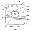
- the guide webs 1011, 1012 have on their side facing away from the ends 1021, 1022 of the primary winding, the threading or insertion side, a continuously reduced width, in order to insert these guide webs 1011, 1012 into corresponding grooves 2131 of the in FIG. 4 illustrated lamp base part 21 to facilitate.
- a plurality of knobs 1013 are formed on the outside of the housing 1010, which also engage in grooves 2131, 2142 of the lamp base part 21.
- an angled, rigid metal sheet 1030 is arranged, which is electrically conductively connected to the second end of the secondary winding of the rod core transformer 1000.
- This metal sheet 1030 forms the high-voltage output of the rod core transformer 1000.
- the housing 1010 of the transformer 1000 has two vent holes 1014, 1015, the encapsulation of the cavities of the lamp base penetration of the potting compound into the housing 1010 and escape of air from the housing 1010 of the transformer enable.
- FIG. 4 is designed as a plastic injection molded socket base part 21 is shown.
- This plastic injection molded part 21 is part of the lamp cap 2 of in FIG. 6 schematically illustrated high-pressure discharge lamp, which serves as a light source for a motor vehicle headlight.
- This high-pressure discharge lamp has a discharge vessel 11 made of quartz glass surrounded by a glass outer bulb 12 and having electrodes 13, 14 arranged therein for generating a gas discharge.
- the electrodes 13, 14 are each connected to a led out of the discharge vessel 11 power supply 15 and 16, via which they are supplied with electrical energy.
- the existing from the discharge vessel 11 and the outer bulb 12 assembly 1 is fixed in the lamp base 2.
- the lamp base 2 comprises a base outer part 21 and a cover 22 which closes the chambers of the base outer part 21, and a connection socket 40 for supplying power to the high-pressure discharge lamp.
- the base outer part 21 has a substantially square cross-section.
- the interior of the base outer part 21 is divided by a partition wall 213 into two chambers 214, 215 of different sizes.
- the rod core transformer 1000 is mounted, which serves as an ignition transformer for accommodated in the lamp base 2 pulse ignition device of the high pressure discharge lamp.
- second chamber 215 further components 61, 62 of the pulse ignition device are arranged.
- an electrical contact element is embedded. It consists of a stainless steel and forms with the base outer part 21 a structural unit. Its ends 31, 32 have flat contact surfaces.
- the first end 31 of the electrical contact element extends into the first chamber 214 and is welded after the assembly of the rod core transformer 1000 with the high voltage leading ignition voltage output 1030 of the rod core transformer 1000.
- the second end 32 of the electrical contact element which is provided with a through hole 33 for the inner power supply 15 of the high-pressure discharge lamp, extends into the second chamber 215.
- a trough 2171 is provided, which is delimited by a hollow cylindrical web 217 , The second end 32 of the contact element forms part of the tank bottom.
- the well 2171 is filled with an electrically insulating potting compound, so that the weld between the two lamp components 15, 32 is embedded in the potting compound.
- the recirculated in the base 2 end of the socket remote from the base end of the discharge vessel 11 outer power supply 16 extends into the hollow cylindrical web 218, which is also formed on the base outer part 21.
- Further hollow-cylindrical webs 219 serve for fastening the cover 22 and for fastening the connection socket 40, which forms the electrical connection of the high-pressure discharge lamp.
- the end of the web 218 is provided with a bearing surface 2181 for a mounting plate 50, the shape of which is matched to the cross section of the second chamber 215.
- the mounting board 50 closes after mounting the chamber 215.
- a plurality of grooves 2142, 2131 for the guide webs 1011, 1012 and studs 1013 of the rod core transformer 1000 are arranged. These grooves 2142, 2131 are matched to guide webs 1011, 1012 or to the studs 1013 on the housing 1010 of the rod core transformer 1010, so that the position of the rod core transformer 1000 in the first chamber 214 is determined thereby.
- the ignition voltage output 1030 of the rod core transformer is welded to this end 31.
- the ends 1021, 1022 of the primary winding 1020 are each angled and connected to a conductor track of the mounting board 50.
- the housing 1010 of the rod core transformer 1000 is seated on the nub 2144 serving as a spacer.
- the space between the rod core transformer 1000 and the side walls 2151, 213 of the first chamber 214 is filled with an electrically insulating potting compound.
- the potting compound also penetrates into the interior of the transformer housing 1010 through the vent openings 1014, 1015.
- the lid 22 covers the mounting board 50 and closes both chambers 214, 215 of the base outer part 21st
Landscapes
- Engineering & Computer Science (AREA)
- Power Engineering (AREA)
- Arrangement Of Elements, Cooling, Sealing, Or The Like Of Lighting Devices (AREA)
- Circuit Arrangements For Discharge Lamps (AREA)
- Common Detailed Techniques For Electron Tubes Or Discharge Tubes (AREA)
- Connecting Device With Holders (AREA)
- Non-Portable Lighting Devices Or Systems Thereof (AREA)
- Vessels And Coating Films For Discharge Lamps (AREA)
Description
- Die Erfindung betrifft einen Transformator gemäß des Obergebgriffs des Patentanspruchs 1 und einen Lampensockel mit einem derartigen Transformator sowie eine Hochdruckentladungslampe mit einem derartigen Lampensockel. Der Transformator dient beispielsweise als Zündtransformator zum Erzeugen von Hochspannungsimpulsen zum Zünden der Gasentladung in dem Entladungsmedium einer Hochdruckentladungslampe.
- Ein derartiger Transformator und ein derartiger Lampensockel sind beispielsweise in der
Offenlegungsschrift WO 00/59269 - Es ist die Aufgabe der Erfindung, einen Transformator bereitzustellen, der zur Montage in einem Lampensockel geeignet ist und der mittels Fertigungsautomaten an einer automatisierten Fertigungsanlage in den Lampensockel eingesetzt und kontaktiert werden kann.
- Diese Aufgabe wird erfindungsgemäß durch die Merkmale des Patentanspruchs 1 bzw. 9 gelöst. Besonders vorteilhafte Ausführungen der Erfindung sind in den abhängigen Patentansprüchen beschrieben.
- Der erfindungsgemäße Transformator besitzt ein Gehäuse, das mindestens eine Wicklung des Transformators umschließt, und sein Gehäuse ist mit Führungsmitteln ausgestattet, die zum lagerichtigen Einbau des Transformators in einem Lampensockel dienen. Diese Führungsmittel erlauben die Montage und Kontaktierung des Transformators in dem Lampensockel mittels Fertigungsautomaten an einer automatisierten Fertigungsanlage. Insbesondere gewährleisten die Führungsmittel die korrekte räumliche Anordnung und Ausrichtung der elektrischen Anschlüsse des Transformators bezüglich des Lampensockels.
- Die Führungsmittel umfassen vorteilhaft mindestens einen Führungssteg, der an der Außenseite des Transformatorsgehäuses angeformt ist. Dieser Führungssteg lässt sich vorteilhaft auf eine entsprechende Nut in der Innenwand des Lampensockels abstimmen, so dass durch ein Zusammenwirken des mindestens einen Führungssteges und der mindestens einen Nut mit einfachen Mitteln ein lagerichtiger Einbau des Transformators in dem Lampensockel gewährleistet wird. Um das Einführen des mindestens einen Führungssteges in die entsprechende mindestens eine Nut zu erleichtern, kann der mindestens eine Führungssteg auf einer Seite, der Einfädelungsoder Einführungsseite, eine reduzierte Breite aufweisen. Der vorgenannte Führungssteg kann zusätzlich in vorteilhafter Weise zur Ausrichtung und Führung der elektrischen Anschlüsse des Transformators verwendet werden. Zu diesem Zweck ist der mindestens eine Führungssteg hohl ausgebildet und durch diesen Führungssteg ein Ende einer Wicklung des Transformators hindurchgeführt. Dieses Ende der Wicklung bildet einen elektrischen Anschluss des Transformators. Es erhält durch den hohlen Führungssteg eine erhöhte mechanische Stabilität. Außerdem wird vorteilhaft auch ein elektrischer Anschluss des Transformators zur korrekten räumlichen Ausrichtung des Transformators verwendet, indem dieser Anschluss als steifes Metallband oder als steifes Metallblech ausgebildet ist. Dieser so ausgebildete elektrische Anschluss bildet zusammen mit einem im Lampensockel angeordneten elektrischen Kontaktelement einen Tiefenanschlag für den Transformator. Bei dem erfindungsgemäßen Transformator handelt es sich in vorteilhafter Weise um einen Stabkerntransformator, da dieser eine im Vergleich zu anderen Transformatoren, wie beispielsweise Ringkerntransformatoren, eine geringe räumliche Ausdehnung besitzt und daher besser für die Montage unter beengten Verhältnissen in einem Lampensockel-geeignet ist. Gemäß des bevorzugten Ausführungsbeispiels der Erfindung sind die Enden der mindestens einen Primärwicklung des Transformators jeweils durch einen hohlen Führungssteg hindurchgeführt, wobei ein Ende der mindestens einen Primärwicklung mit einem ersten Ende der mindestens einen Sekundärwicklung des Transformators elektrisch leitend verbunden ist und ein zweites Ende der mindestens einen Sekundärwicklung des Transformators mit dem als steifes Metallband oder Metallblech ausgebildeten elektrischen Anschluss des Transformators verbunden ist. Die beiden vorgenannten Enden der Primärwicklung dienen als elektrische Anschlüsse zur Spannungsversorgung des Transformators. Die hohlen Führungsstege dienen zur mechanischen Stabilisierung der Primärwicklungsenden und zum lagerichtigen Einbau des Transformators in den Lampensockel, während der mit dem vorgenannten zweiten Ende der mindestens einen Sekundärwicklung elektrisch leitend verbundene, als steifes Metallband oder Metallblech ausgebildete elektrische Anschluss des Transformators den Hochspannungsausgang des Transformators bildet, der zusammen mit einem in dem Lampensockel angeordneten elektrischen Kontaktelement als Tiefenanschlag für den Transformator dient.
- Der erfindungsgemäße Lampensockel weist einen in einer Kammer des Lampensockels angeordneten Transformator auf, dessen Gehäuse mindestens eine Wicklung des Transformators umschließt, wobei erfindungsgemäß die Wände der Kammer und das Gehäuse des Transformators mit aufeinander abgestimmten Führungsmitteln versehen sind, die zum lagerichtigen Einbau des Transformators in der Kammer dienen. Wie bereits oben erwähnt wurde, erlauben die Führungsmittel die Montage und Kontaktierung des Transformators in dem Lampensockel mittels Fertigungsautomaten an einer automatisierten Fertigungsanlage und gewährleisten insbesondere die korrekte räumliche Anordnung und Ausrichtung der elektrischen Anschlüsse des Transformators bezüglich des Lampensockels.
- Die Führungsmittel umfassen vorzugsweise auch mindestens einen Führungssteg, der an der Außenseite des Gehäuses des Transformators angeformt ist, sowie mindestens eine an der Innenwand der Kammer angeordnete und auf den mindestens einen Führungssteg abgestimmte Nut. Um die Montage des Transformators in der Kammer des Lampensockels zu erleichtern, kann der mindestens eine Führungssteg auf einer Seite, der Einfädelungs- oder Einführungsseite, eine reduzierte Breite besitzen o-der / und die mindestens eine Nut auf der Einführungsseite eine im Vergleich zur Führungsstegbreite vergrößerte Breite aufweisen. Neben dem vorgenannten Führungssteg können die Führungsmittel auch an der Außenseite des Gehäuses angeformte Noppen umfassen, die ebenfalls in Nuten an der Innenwand der Lampensockelkammer eingreifen.
- Der Boden der Kammer des Lampensockels, in welcher der Transformator angeordnet ist, weist vorzugsweise einen Abstandshalter auf, der neben dem elektrischen Kontaktelement, auf dem der als steifes Metallband oder Metallblech ausgebildete Transformatoranschluss aufsitzt, einen zweiten Tiefenanschlag für die Montage des Transformators in der Kammer bildet.
- Der erfindungsgemäße Lampensockel wird vorzugsweise als Sockel einer Hochdruckentladungslampe verwendet, wobei der Transformator als Zündtransformator einer in dem Lampensockel integrierten Impulszündvorrichtung ausgebildet ist.
- Nachstehend wird die Erfindung anhand eines bevorzugten Ausführungsbeispiels näher erläutert. Es zeigen:
- Figur 1
- Eine Seitenansicht eines Transformators gemäß des bevorzugten Ausführungsbeispiels der Erfindung
- Figur 2
- Eine Draufsicht auf den in
Figur 1 abgebildeten Transformator - Figur 3
- Eine Draufsicht auf eine Stirnseite des in
Figur 1 abgebildeten Transformators - Figur 4
- Eine Draufsicht auf die Kammer eines noch offenen Lampensockels, die für die Aufnahme des in
Figur 1 abgebildeten Transformators vorgesehen ist - Figur 5
- Eine Draufsicht auf die im Lampensockel angeordnete Montageplatine
- Figur 6
- Eine Seitenansicht einer Hochdruckentladungslampe mit dem erfindungsgemäßen Lampensockel
- Bei dem in
Figur 1 abgebildeten, bevorzugten Ausführungsbeispiel des erfindungsgemäßen Transformator handelt es sich um einen Stabkerntransformator 1000, der den Zündtransformator einer in dem Lampensockel der inFigur 6 dargestellten Hochdruckentladungslampe integrierten Impulszündvorrichtung bildet. Der Stabkerntransformator 1000 besitzt einen stabförmigen Ferritkern 1001, auf den eine Sekundärwicklung des Transformators 1000 gewickelt ist. Der Ferritkern 1001 und die darauf angeordnete Sekundärwicklung sind nahezu vollständig von dem aus Kunststoff bestehenden Gehäuse 1010 des Stabkerntransformators 1000 umschlossen. Der Stabkerntransformator 1000 besitzt eine Primärwicklung 1020, die außerhalb des Gehäuses 1010 angeordnet und um die Außenseite des Gehäuses 1010 gewickelt ist. Die Primärwicklung 1020 besteht aus einem Metallband und besitzt drei Windungen. Die Enden 1021, 1022 der Primärwicklung sind jeweils durch einen an der Außenseite des Gehäuses angeformten, hohlen Führungssteg 1011, 1012 hindurchgeführt. Die aus den Führungsstegen 1011, 1012 herausragenden Enden 1021, 1022 der Primärwicklung 1020 bilden die zur Spannungsversorgung dienenden elektrischen Anschlüsse des Stabkerntransformators 1000. Das erste Ende 1021 der Primärwicklung 1020 ist elektrisch leitend mit dem ersten, aus dem Gehäuse 1010 herausragenden Ende 1023 der Sekundärwicklung (nicht abgebildet) verbunden. Die ersten Enden 1021, 1023 der Primärwicklung und der Sekundärwicklung befinden sich daher während des Betriebs auf demselben elektrischen Potential, üblicherweise auf dem Massepotential. Die Führungsstege 1011, 1012 und die Enden 1021, 1022 der Primärwicklung 1020 erstrecken sich quer zur Längsachse des Ferritkerns 1001 bzw. des Transformators 1000. Die Führungsstege 1011, 1012 besitzen auf ihrer von den Enden 1021, 1022 der Primärwicklung abgewandten Seite, der Einfädelungs- oder Einführungsseite, eine kontinuierlich reduzierte Breite, um das Einführen dieser Führungsstege 1011, 1012 in entsprechende Nuten 2131 des inFigur 4 abgebildeten Lampensockelteils 21 zu erleichtern. Außerdem sind an der Außenseite des Gehäuses 1010 noch mehrere Noppen 1013 angeformt, die ebenfalls in Nuten 2131, 2142 des Lampensockelteils 21 eingreifen. - An einer Stirnseite des Stabkerntransformators 1000 ist ein abgewinkeltes, steifes Metallblech 1030 angeordnet, das elektrisch leitend mit dem zweiten Ende der Sekundärwicklung des Stabkerntransformators 1000 verbunden ist. Dieses Metallblech 1030 bildet den Hochspannungsausgang des Stabkerntransformators 1000. Das Gehäuse 1010 des Transformators 1000 weist zwei Entlüftungsöffnungen 1014, 1015 auf, die beim Vergießen der Hohlräume des Lampensockels ein Eindringen der Vergussmasse in das Gehäuse 1010 und ein Entweichen der Luft aus dem Gehäuse 1010 des Transformators ermöglichen.
- In der
Figur 4 ist ein als Kunststoffspritzgussteil ausgebildetes Sockelaußenteil 21 dargestellt. Dieses Kunststoffspritzgussteil 21 ist Bestandteil des Lampensockels 2 der inFigur 6 schematisch dargestellten Hochdruckentladungslampe, die als Lichtquelle für einen Kraftfahrzeugscheinwerfer dient. Diese Hochdruckentladungslampe besitzt ein von einem gläsernen Außenkolben 12 umschlossenes Entladungsgefäß 11 aus Quarzglas mit darin angeordneten Elektroden 13, 14 zum Erzeugen einer Gasentladung. Die Elektroden 13, 14 sind jeweils mit einer aus dem Entladungsgefäß 11 herausgeführten Stromzuführung 15 bzw. 16 verbunden, über die sie mit elektrischer Energie versorgt werden. Die aus dem Entladungsgefäß 11 und dem Außenkolben 12 bestehenden Baueinheit 1 ist im Lampensockel 2 fixiert. Der Lampensockel 2 umfasst ein Sockelaußenteil 21 und einen Deckel 22, der die Kammern des Sockelaußenteils 21 verschließt, sowie eine Anschlussbuchse 40 zur Spannungsversorgung der Hochdruckentladungslampe. - Das Sockelaußenteil 21 besitzt einen im wesentlichen quadratischen Querschnitt. Der Innenraum des Sockelaußenteils 21 wird durch eine Trennwand 213 in zwei unterschiedlich große Kammern 214, 215 unterteilt. In der kleineren, ersten Kammer 214 wird der Stabkerntransformator 1000 montiert, der als Zündtransformator für die im Lampensockel 2 untergebrachte Impulszündvorrichtung der Hochdruckentladungslampe dient. In der größeren, zweiten Kammer 215 sind weitere Komponenten 61, 62 der Impulszündvorrichtung angeordnet. In dem Sockelaußenteil 21 ist ein elektrisches Kontaktelement eingebettet. Es besteht aus einem Edelstahl und bildet mit dem Sockelaußenteil 21 eine Baueinheit. Seine Enden 31, 32 besitzen ebene Kontaktflächen. Das erste Ende 31 des elektrischen Kontaktelementes erstreckt sich in die erste Kammer 214 und ist nach der Montage des Stabkerntransformators 1000 mit dem Hochspannung führenden Zündspannungsausgang 1030 des Stabkerntransformators 1000 verschweißt. Das zweite Ende 32 des elektrischen Kontaktelementes, das mit einer durchgehenden Bohrung 33 für die innere Stromzuführung 15 der Hochdruckentladungslampe versehen ist, erstreckt sich in die zweite Kammer 215. In dem Sockelaußenteil 21 ist eine Wanne 2171 vorgesehen, die durch einen hohlzylindrischen Steg 217 begrenzt wird. Das zweite Ende 32 des Kontaktelementes bildet einen Teil des Wannenbodens. Nach dem Verschweißen der inneren Stromzuführung 15 mit dem zweiten Ende 32 des Kontaktelementes wird die Wanne 2171 mit einer elektrisch isolierenden Vergussmasse ausgefüllt, so dass die Schweißstelle zwischen den beiden Lampenkomponenten 15, 32 in der Vergussmasse eingebettet ist. Das in den Sockel 2 zurückgeführte Ende der aus dem sockelfernen Ende des Entladungsgefäßes 11 herausragenden äußeren Stromzuführung 16 erstreckt sich in den hohlzylindrischen Steg 218, der ebenfalls an dem Sockelaußenteil 21 angeformt ist. Weitere hohlzylindrische Stege 219 dienen zur Befestigung des Deckels 22 und zur Befestigung der Anschlussbuchse 40, die den elektrischen Anschluss der Hochdruckentladungslampe bildet. Das Ende des Steges 218 ist mit einer Auflagefläche 2181 für eine Montageplatine 50, deren Form passgerecht auf den Querschnitt der zweiten Kammer 215 abgestimmt ist, ausgestattet. Die Montageplatine 50 verschließt nach ihrer Montage die Kammer 215. Die auf der Montageplatine 50 angeordneten Bauteile, wie zum Beispiel der Zündkondensator 61 und die Funkenstrecke 62 der Impulszündvorrichtung, ragen in die zweite Kammer 215 hinein. In den Seitenwänden 2151, 213 der ersten Kammer 214 sind mehrere Nuten 2142, 2131 für die Führungsstege 1011, 1012 und Noppen 1013 des Stabkemtransformators 1000 angeordnet. Diese Nuten 2142, 2131 sind passgerecht auf Führungsstege 1011, 1012 bzw. auf die Noppen 1013 am Gehäuse 1010 des Stabkerntransformators 1010 abgestimmt, so dass die Position des Stabkerntransformators 1000 in der ersten Kammer 214 dadurch festgelegt ist. Zusätzlich befindet sich in dem Boden 2143 der Kammer 214 eine Noppe 2144, die zusammen mit dem ersten Ende 31 des Kontaktelementes und dem darauf aufsitzenden Zündspannungsausgang 1030 des Transformators 1000 die Einbautiefe des Stabkerntransformators 1000 bestimmt. Der Zündspannungsausgang 1030 des Stabkerntransformators ist mit diesem Ende 31 verschweißt. Die Enden 1021, 1022 der Primärwicklung 1020 sind jeweils abgewinkelt und mit einer Leiterbahn der Montageplatine 50 verbunden. Das Gehäuse 1010 des Stabkerntransformators 1000 sitzt auf der als Abstandshalter dienenden Noppe 2144 auf. Der Zwischenraum zwischen dem Stabkerntransformator 1000 und den Seitenwänden 2151, 213 der ersten Kammer 214 wird mit einer elektrisch isolierenden Vergussmasse ausgefüllt. Die Vergussmasse dringt durch die Entlüftungsöffnungen 1014, 1015 auch in den Innenraum des Transformatorgehäuses 1010 ein. Der Deckel 22 deckt die Montageplatine 50 ab und verschließt beide Kammern 214, 215 des Sockelaußenteils 21.
Claims (17)
- Transformator zur Montage in einem Lampensockel, wobei der Transformator (1000) ein Gehäuse (1010) aufweist, das mindestens eine Wicklung des Transformators (1000) umschließt,
dadurch gekennzeichnet, dass das Gehäuse (1010) mit Führungsmitteln (1011, 1012, 1013) versehen ist, die zum lagerichtigen Einbau des Transformators (1000) in einem Lampensockel dienen. - Transformator nach Anspruch 1, dadurch gekennzeichnet, dass die Führungsmittel mindestens einen an der Außenseite des Gehäuses (1010) angeformten Führungssteg (1011) umfassen.
- Transformator nach Anspruch 2, dadurch gekennzeichnet, dass der mindestens eine Führungssteg (1011) hohl ausgebildet ist und durch diesen Führungssteg (1011) ein Ende (1021) einer Wicklung (1020) des Transformators (1000) hindurchgeführt ist.
- Transformator nach Anspruch 2, dadurch gekennzeichnet, dass der mindestens eine Führungssteg (1011) auf seiner Einführungsseite eine verringerte Breite besitzt.
- Transformator nach Anspruch 1, dadurch gekennzeichnet, dass das Gehäuse (1010) mindestens eine Entlüftungsöffnung (1014) aufweist.
- Transformator nach Anspruch 1, dadurch gekennzeichnet, dass ein elektrischer Anschluss (1030) des Transformators (1000) als steifes Metallband oder als steifes Metallblech ausgebildet ist.
- Transformator nach Anspruch 1, dadurch gekennzeichnet, dass der Transformator (1000) ein Stabkerntransformator ist.
- Transformator nach den Ansprüchen 3, 6 und 7, dadurch gekennzeichnet, dass die beiden Enden (1021, 1022) der mindestens einer Primärwicklung (1020) des Transformators (1000) jeweils durch einen hohlen Führungssteg (1011, 1012) hindurchgeführt sind, ein Ende (1021) der mindestens einen Primärwicklung (1020) mit einem ersten Ende (1023) mindestens einer Sekundärwicklung des Transformators (1000) elektrisch leitend verbunden ist und ein zweites Ende der mindestens einen Sekundärwicklung mit dem als steifes Metallband oder als steifes Metallblech ausgebildeten elektrischen Anschluss (1030) des Transformators (1000) verbunden ist.
- Lampensockel mit einem in einer Kammer (214) des Lampensockels (2) angeordneten Transformator (1000), wobei der Transformator (1000) ein Gehäuse (1010) aufweist, das mindestens eine Wicklung des Transformators (1000) umschließt,
dadurch gekennzeichnet, dass die Wände (2151, 213) der Kammer (214) und das Gehäuse (1010) des Transformators (1000) mit aufeinander abgestimmten Führungsmitteln (2131, 2142, 1011, 1012, 1013) versehen sind, die zum lagerichtigen Einbau des Transformators (1000) in der Kammer (214) dienen. - Lampensockel nach Anspruch 9, dadurch gekennzeichnet, dass die Führungsmittel mindestens einen Führungssteg (1011), der an der Außenseite des Gehäuses (1010) des Transformators (1000) angeformt ist, sowie mindestens eine an der Innenwand der Kammer (214) angeordnete und auf den Führungssteg (1011) abgestimmte Nut (2131) umfassen.
- Lampensockel nach Anspruch 10, dadurch gekennzeichnet, dass der mindestens eine Führungssteg (1011) hohl ausgebildet ist und durch diesen Führungssteg ein Ende (1021) einer Wicklung (1020) des Transformators (1000) hindurchgeführt ist.
- Lampensockel nach Anspruch 10, dadurch gekennzeichnet, dass der mindestens eine Führungssteg (1011) auf seiner Einführungsseite eine reduzierte Breite besitzt und / oder die mindestens eine Nut auf der Einführungsseite eine vergrößerte Breite aufweist.
- Lampensockel nach Anspruch 9, dadurch gekennzeichnet, dass der Transformator (1000) einen elektrischen Anschluss (1030) besitzt, der aus einem steifen Metallband oder einem steifen Metallblech besteht und der auf einem sich in die Kammer (214) erstreckenden elektrischen Kontaktelement (3) des Lampensockels (2) aufsitzt.
- Lampensockel nach Anspruch 9 oder 13, dadurch gekennzeichnet, dass zwischen dem Gehäuse (1010) des Transformators (1000) und dem Boden (2143) der Kammer ein Abstandshalter (2144) angeordnet ist.
- Lampensockel nach Anspruch 9, dadurch gekennzeichnet, dass der Transformator (1000) ein Stabkemtransformator ist.
- Lampensockel nach den Ansprüchen 9, 11 und 13, dadurch gekennzeichnet, dass die beiden Enden (1021, 1022) mindestens einer Primärwicklung (1020) des Transformators (1000) jeweils durch einen hohlen Führungssteg (1011, 1012) hindurchgeführt sind, ein Ende (1021) der mindestens einen Primärwicklung (1020) mit einem ersten Ende (1023) mindestens einer Sekundärwicklung des Transformators (1000) elektrisch leitend verbunden ist und ein zweites Ende der mindestens einen Sekundärwicklung mit dem als steifes Metallband oder als steifes Metallblech ausgebildeten elektrischen Anschluss (1030) des Transformators (1000) verbunden ist.
- Hochdruckentladungslampe mit einem Lampensockel nach einem oder mehreren der Ansprüche 9 bis 16.
Applications Claiming Priority (2)
| Application Number | Priority Date | Filing Date | Title |
|---|---|---|---|
| DE10339587 | 2003-08-26 | ||
| DE10339587A DE10339587A1 (de) | 2003-08-26 | 2003-08-26 | Transformator, Lampensockel mit einem Transformator und Hochdruckentladungslampe |
Publications (3)
| Publication Number | Publication Date |
|---|---|
| EP1511131A1 EP1511131A1 (de) | 2005-03-02 |
| EP1511131B1 true EP1511131B1 (de) | 2011-09-21 |
| EP1511131B8 EP1511131B8 (de) | 2012-03-28 |
Family
ID=34089226
Family Applications (1)
| Application Number | Title | Priority Date | Filing Date |
|---|---|---|---|
| EP04017001A Expired - Lifetime EP1511131B8 (de) | 2003-08-26 | 2004-07-19 | Transformator, Lampensockel mit einem Transformator und Hochdruckentladungslampe |
Country Status (10)
| Country | Link |
|---|---|
| US (1) | US7135822B2 (de) |
| EP (1) | EP1511131B8 (de) |
| JP (1) | JP4813780B2 (de) |
| KR (1) | KR101169070B1 (de) |
| CN (1) | CN100467943C (de) |
| AT (1) | ATE525773T1 (de) |
| CA (1) | CA2479078A1 (de) |
| DE (1) | DE10339587A1 (de) |
| ES (1) | ES2374129T3 (de) |
| TW (1) | TWI386107B (de) |
Families Citing this family (20)
| Publication number | Priority date | Publication date | Assignee | Title |
|---|---|---|---|---|
| DE102004058881A1 (de) * | 2004-12-06 | 2006-06-08 | Patent-Treuhand-Gesellschaft für elektrische Glühlampen mbH | Hochdruckentladungslampe und Beleuchtungsvorrichtung mit Hochdruckentladungslampe |
| DE102005029001A1 (de) * | 2005-02-11 | 2006-08-24 | Patent-Treuhand-Gesellschaft für elektrische Glühlampen mbH | Lampensockel für eine Hochdruckentladungslampe und Hochdrucksentladungslampe |
| DE102005038043A1 (de) * | 2005-08-09 | 2007-02-15 | Patent-Treuhand-Gesellschaft für elektrische Glühlampen mbH | Lampensockel für eine Hochdruckentladungslampe und Hochdruckentladungslampe |
| KR100738704B1 (ko) * | 2005-10-06 | 2007-07-12 | 엘지전자 주식회사 | 영상 디스플레이 기기용 스탠드 |
| US7855625B2 (en) * | 2006-08-31 | 2010-12-21 | General Electric Company | Lamp transformer |
| US8072308B2 (en) * | 2007-02-26 | 2011-12-06 | General Electric Company | High voltage transformer and a novel arrangement/method for hid automotive headlamps |
| ITTO20070217A1 (it) * | 2007-03-26 | 2008-09-27 | Itw Ind Components S R L Co N | Dispositivo accendigas ad alto rendimento per un elettrodomestico, in particolare un piano di cottura |
| US7868554B2 (en) * | 2007-05-18 | 2011-01-11 | General Electric Company | Light weight automotive HID igniter |
| DE102007037635A1 (de) | 2007-08-09 | 2009-02-12 | Osram Gesellschaft mit beschränkter Haftung | Transformator sowie Lampensockel und Entladungslampe mit einem derartigen Transformator |
| DE102008031254A1 (de) | 2008-07-02 | 2010-01-07 | Osram Gesellschaft mit beschränkter Haftung | Hochdruckentladungslampe |
| DE102008033192A1 (de) | 2008-07-15 | 2010-01-21 | Osram Gesellschaft mit beschränkter Haftung | Transformator sowie Lampensockelelement, Lampensockel und Entladungslampe mit einem derartigen Lampensockel |
| DE102009012090A1 (de) | 2009-03-06 | 2010-09-09 | Hella Kgaa Hueck & Co. | Zündtransformator für eine Hochdruckgasentladungslampe |
| DE102009012087A1 (de) * | 2009-03-06 | 2010-09-09 | Hella Kgaa Hueck & Co. | Zündtransformator für eine Hochdruckgasentladungslampe |
| DE102009012088A1 (de) | 2009-03-06 | 2010-09-09 | Hella Kgaa Hueck & Co. | Zündgerät für eine Hochdruckgasentladungslampe |
| DE102009012089A1 (de) | 2009-03-06 | 2010-09-09 | Hella Kgaa Hueck & Co. | Zündgerät für eine Hochdruckgasentladungslampe |
| DE102009018448A1 (de) * | 2009-04-22 | 2010-10-28 | Automotive Lighting Reutlingen Gmbh | Beleuchtungseinrichtung eines Kraftfahrzeugs |
| DE102009054376B4 (de) * | 2009-11-11 | 2011-09-01 | Osram Gesellschaft mit beschränkter Haftung | Hochdruckentladungslampe |
| DE102010040454A1 (de) | 2010-09-09 | 2012-01-19 | Osram Ag | Transformator und Hochdruckentladungslampe mit Transformator |
| DK2983194T3 (en) | 2014-08-04 | 2018-05-22 | Flowil Int Lighting Holding B V | REMOVABLE ENERGY SAVE LIGHT WITH INTEGRATED MAGNETIC COIL AND CERAMIC METAL HALOGEN LIGHT PIPE FOR REPLACEMENT OF MERCURY Vapor Lamps, HIGH PRESSURE SODIUM LAMPS AND QUARTER METAL HALOGS |
| DE102015210506A1 (de) | 2015-06-09 | 2016-12-15 | Osram Gmbh | Zündvorrichtung für eine Hochdruckentladungslampe |
Family Cites Families (17)
| Publication number | Priority date | Publication date | Assignee | Title |
|---|---|---|---|---|
| US3360687A (en) * | 1965-09-28 | 1967-12-26 | Gen Electric | Lamp ballast |
| US3655906A (en) * | 1970-10-19 | 1972-04-11 | Gen Electric | Lamp ballast and method of producing same |
| JPH0614444Y2 (ja) * | 1985-08-20 | 1994-04-13 | ソニー株式会社 | トランス |
| US4746840A (en) * | 1987-04-06 | 1988-05-24 | Lim Kenneth S | Fluorescent reflector lamp assembly |
| US4939420A (en) * | 1987-04-06 | 1990-07-03 | Lim Kenneth S | Fluorescent reflector lamp assembly |
| US4916363A (en) * | 1988-10-14 | 1990-04-10 | Valmont Industries, Inc. | Ballast |
| JPH03206605A (ja) * | 1990-01-09 | 1991-09-10 | Matsushita Electric Ind Co Ltd | チョークトランス |
| US5510967A (en) * | 1994-12-13 | 1996-04-23 | Osram Sylvania Inc. | Hid headlamp assembly |
| DE19652309A1 (de) * | 1996-12-16 | 1998-06-18 | Whitaker Corp | Anordnung zur Kontaktierung eines Teils mit einem Sockel, insbesondere einer Gasentladungslampe |
| US6084354A (en) * | 1997-03-06 | 2000-07-04 | Ngk Spark Plug Co., Ltd. | Vehicle-lamp lighting-on device |
| US6124673A (en) * | 1997-04-07 | 2000-09-26 | Bishop; James G. | Universal arc-discharge lamp systems |
| JPH1167558A (ja) * | 1997-08-22 | 1999-03-09 | Tec Corp | 電磁機器 |
| DE19831042A1 (de) * | 1998-07-13 | 2000-02-17 | Patent Treuhand Ges Fuer Elektrische Gluehlampen Mbh | Beleuchtungssystem mit einer Hochdruckentladungslampe |
| DE19913942C1 (de) | 1999-03-26 | 2000-04-13 | Vogt Electronic Ag | Gasentladungslampensockel mit Zündeinrichtung |
| CN1146089C (zh) * | 1999-09-30 | 2004-04-14 | 松下电工株式会社 | 灯座和放电灯发光装置 |
| JP2002075757A (ja) * | 2000-06-14 | 2002-03-15 | Denso Corp | 変圧装置およびそれを用いた高電圧発生装置ならびに放電灯装置 |
| JP3882510B2 (ja) * | 2001-01-19 | 2007-02-21 | 松下電工株式会社 | 放電灯点灯装置およびその製造方法 |
-
2003
- 2003-08-26 DE DE10339587A patent/DE10339587A1/de not_active Withdrawn
-
2004
- 2004-07-19 ES ES04017001T patent/ES2374129T3/es not_active Expired - Lifetime
- 2004-07-19 AT AT04017001T patent/ATE525773T1/de active
- 2004-07-19 EP EP04017001A patent/EP1511131B8/de not_active Expired - Lifetime
- 2004-08-17 JP JP2004237736A patent/JP4813780B2/ja not_active Expired - Fee Related
- 2004-08-18 US US10/920,420 patent/US7135822B2/en not_active Expired - Lifetime
- 2004-08-20 TW TW093125151A patent/TWI386107B/zh not_active IP Right Cessation
- 2004-08-25 KR KR1020040067138A patent/KR101169070B1/ko not_active Expired - Fee Related
- 2004-08-25 CA CA002479078A patent/CA2479078A1/en not_active Abandoned
- 2004-08-26 CN CNB2004100579275A patent/CN100467943C/zh not_active Expired - Fee Related
Also Published As
| Publication number | Publication date |
|---|---|
| TWI386107B (zh) | 2013-02-11 |
| CA2479078A1 (en) | 2005-02-26 |
| DE10339587A1 (de) | 2005-03-24 |
| JP2005072583A (ja) | 2005-03-17 |
| EP1511131A1 (de) | 2005-03-02 |
| TW200518631A (en) | 2005-06-01 |
| ATE525773T1 (de) | 2011-10-15 |
| JP4813780B2 (ja) | 2011-11-09 |
| US20050068143A1 (en) | 2005-03-31 |
| CN1590841A (zh) | 2005-03-09 |
| KR20050021276A (ko) | 2005-03-07 |
| US7135822B2 (en) | 2006-11-14 |
| EP1511131B8 (de) | 2012-03-28 |
| CN100467943C (zh) | 2009-03-11 |
| ES2374129T3 (es) | 2012-02-14 |
| KR101169070B1 (ko) | 2012-07-26 |
Similar Documents
| Publication | Publication Date | Title |
|---|---|---|
| EP1511131A1 (de) | Transformator, Lampensockel mit einem Transformator und Hochdruckentladungslampe | |
| DE19928567C2 (de) | Transformator und Verfahren zu dessen Zusammenbau | |
| EP1511130B1 (de) | Hochdruckentladungslampe | |
| WO2013057266A1 (de) | Hochspannungstransformator und bewickelter spulenkörper für zündmodule mit anschlussstiften als bestandteil der primärwicklung | |
| DE69114628T2 (de) | Rücklauftransistor. | |
| EP1847159B1 (de) | Lampensockel für eine hochdruckentladungslampe und hochdruckentladungslampe | |
| EP1511132B1 (de) | Lampensockel für eine Hochdruckentladungslampe und Hochdruckentladungslampe | |
| DE102007025421B4 (de) | Zündtransformator und Zündmodul | |
| DE102006044436C5 (de) | Vorrichtung zur Energiespeicherung und Energietransformierung | |
| EP1880449B1 (de) | Lampensockel und hochdruckentladungslampe mit einem lampensockel | |
| DE112006003946B4 (de) | Induktives Bauteil mit einem Spulenkörper mit integrierter Wicklung | |
| EP1542246B1 (de) | Zündspule | |
| DE10251841A1 (de) | Elektrische Kontaktierung dünner Lackdrähte von Sekundärwicklungen von Zündspulen | |
| EP1658661B1 (de) | Lampensockel für eine hochdruckentladungslampe und hochdruck entladungslampe | |
| EP1913607B1 (de) | Lampensockel für eine hochdruckentladungslampe und hochdruckentladungs- lampe | |
| DE102010040454A1 (de) | Transformator und Hochdruckentladungslampe mit Transformator | |
| DE2817184C3 (de) | Induktivität | |
| DE10251840A1 (de) | Elektrische Kontaktierung dünner Lackdrähte von Sekundärwicklungen von Zündspulen | |
| DE102012201753A1 (de) | Kondensator sowie Verfahren zur Herstellung eines Kondensators | |
| DE3727459C2 (de) | Zündsystem für Brennkraftmaschinen | |
| EP2226817B1 (de) | Zündtransformator für eine Hochdruckgasentladungslampe | |
| DE102007063690B4 (de) | Zündmodul | |
| DE3705759A1 (de) | Anschlussklemmeinrichtung, insbesondere fuer drosseln oder transformatoren | |
| CH534966A (de) | Kontaktstück zum lötfreien Anschliessen eines isolierten, elektrischen Leiters und Verwendung desselben | |
| DE10206379B4 (de) | Elektrisches Feindrahtkontaktierungselement, Feindrahtkontaktierungselementepaar und damit ausgerüstete elektrische Spule |
Legal Events
| Date | Code | Title | Description |
|---|---|---|---|
| PUAI | Public reference made under article 153(3) epc to a published international application that has entered the european phase |
Free format text: ORIGINAL CODE: 0009012 |
|
| AK | Designated contracting states |
Kind code of ref document: A1 Designated state(s): AT BE BG CH CY CZ DE DK EE ES FI FR GB GR HU IE IT LI LU MC NL PL PT RO SE SI SK TR |
|
| AX | Request for extension of the european patent |
Extension state: AL HR LT LV MK |
|
| 17P | Request for examination filed |
Effective date: 20050321 |
|
| AKX | Designation fees paid |
Designated state(s): AT BE BG CH CY CZ DE DK EE ES FI FR GB GR HU IE IT LI LU MC NL PL PT RO SE SI SK TR |
|
| GRAP | Despatch of communication of intention to grant a patent |
Free format text: ORIGINAL CODE: EPIDOSNIGR1 |
|
| RAP1 | Party data changed (applicant data changed or rights of an application transferred) |
Owner name: OSRAM GESELLSCHAFT MIT BESCHRAENKTER HAFTUNG |
|
| GRAS | Grant fee paid |
Free format text: ORIGINAL CODE: EPIDOSNIGR3 |
|
| GRAA | (expected) grant |
Free format text: ORIGINAL CODE: 0009210 |
|
| AK | Designated contracting states |
Kind code of ref document: B1 Designated state(s): AT BE BG CH CY CZ DE DK EE ES FI FR GB GR HU IE IT LI LU MC NL PL PT RO SE SI SK TR |
|
| REG | Reference to a national code |
Ref country code: GB Ref legal event code: FG4D Free format text: NOT ENGLISH |
|
| REG | Reference to a national code |
Ref country code: CH Ref legal event code: EP |
|
| RAP2 | Party data changed (patent owner data changed or rights of a patent transferred) |
Owner name: OSRAM AG |
|
| REG | Reference to a national code |
Ref country code: IE Ref legal event code: FG4D Free format text: LANGUAGE OF EP DOCUMENT: GERMAN |
|
| REG | Reference to a national code |
Ref country code: DE Ref legal event code: R096 Ref document number: 502004012872 Country of ref document: DE Effective date: 20111117 |
|
| REG | Reference to a national code |
Ref country code: NL Ref legal event code: T3 |
|
| REG | Reference to a national code |
Ref country code: SE Ref legal event code: TRGR |
|
| PG25 | Lapsed in a contracting state [announced via postgrant information from national office to epo] |
Ref country code: FI Free format text: LAPSE BECAUSE OF FAILURE TO SUBMIT A TRANSLATION OF THE DESCRIPTION OR TO PAY THE FEE WITHIN THE PRESCRIBED TIME-LIMIT Effective date: 20110921 |
|
| REG | Reference to a national code |
Ref country code: ES Ref legal event code: FG2A Ref document number: 2374129 Country of ref document: ES Kind code of ref document: T3 Effective date: 20120214 |
|
| PG25 | Lapsed in a contracting state [announced via postgrant information from national office to epo] |
Ref country code: GR Free format text: LAPSE BECAUSE OF FAILURE TO SUBMIT A TRANSLATION OF THE DESCRIPTION OR TO PAY THE FEE WITHIN THE PRESCRIBED TIME-LIMIT Effective date: 20111222 Ref country code: SI Free format text: LAPSE BECAUSE OF FAILURE TO SUBMIT A TRANSLATION OF THE DESCRIPTION OR TO PAY THE FEE WITHIN THE PRESCRIBED TIME-LIMIT Effective date: 20110921 Ref country code: CY Free format text: LAPSE BECAUSE OF FAILURE TO SUBMIT A TRANSLATION OF THE DESCRIPTION OR TO PAY THE FEE WITHIN THE PRESCRIBED TIME-LIMIT Effective date: 20110921 |
|
| REG | Reference to a national code |
Ref country code: IE Ref legal event code: FD4D |
|
| PG25 | Lapsed in a contracting state [announced via postgrant information from national office to epo] |
Ref country code: CZ Free format text: LAPSE BECAUSE OF FAILURE TO SUBMIT A TRANSLATION OF THE DESCRIPTION OR TO PAY THE FEE WITHIN THE PRESCRIBED TIME-LIMIT Effective date: 20110921 Ref country code: SK Free format text: LAPSE BECAUSE OF FAILURE TO SUBMIT A TRANSLATION OF THE DESCRIPTION OR TO PAY THE FEE WITHIN THE PRESCRIBED TIME-LIMIT Effective date: 20110921 Ref country code: IE Free format text: LAPSE BECAUSE OF FAILURE TO SUBMIT A TRANSLATION OF THE DESCRIPTION OR TO PAY THE FEE WITHIN THE PRESCRIBED TIME-LIMIT Effective date: 20110921 |
|
| PG25 | Lapsed in a contracting state [announced via postgrant information from national office to epo] |
Ref country code: EE Free format text: LAPSE BECAUSE OF FAILURE TO SUBMIT A TRANSLATION OF THE DESCRIPTION OR TO PAY THE FEE WITHIN THE PRESCRIBED TIME-LIMIT Effective date: 20110921 Ref country code: PL Free format text: LAPSE BECAUSE OF FAILURE TO SUBMIT A TRANSLATION OF THE DESCRIPTION OR TO PAY THE FEE WITHIN THE PRESCRIBED TIME-LIMIT Effective date: 20110921 Ref country code: PT Free format text: LAPSE BECAUSE OF FAILURE TO SUBMIT A TRANSLATION OF THE DESCRIPTION OR TO PAY THE FEE WITHIN THE PRESCRIBED TIME-LIMIT Effective date: 20120123 Ref country code: RO Free format text: LAPSE BECAUSE OF FAILURE TO SUBMIT A TRANSLATION OF THE DESCRIPTION OR TO PAY THE FEE WITHIN THE PRESCRIBED TIME-LIMIT Effective date: 20110921 |
|
| PLBE | No opposition filed within time limit |
Free format text: ORIGINAL CODE: 0009261 |
|
| STAA | Information on the status of an ep patent application or granted ep patent |
Free format text: STATUS: NO OPPOSITION FILED WITHIN TIME LIMIT |
|
| PG25 | Lapsed in a contracting state [announced via postgrant information from national office to epo] |
Ref country code: DK Free format text: LAPSE BECAUSE OF FAILURE TO SUBMIT A TRANSLATION OF THE DESCRIPTION OR TO PAY THE FEE WITHIN THE PRESCRIBED TIME-LIMIT Effective date: 20110921 |
|
| 26N | No opposition filed |
Effective date: 20120622 |
|
| REG | Reference to a national code |
Ref country code: DE Ref legal event code: R097 Ref document number: 502004012872 Country of ref document: DE Effective date: 20120622 |
|
| PG25 | Lapsed in a contracting state [announced via postgrant information from national office to epo] |
Ref country code: MC Free format text: LAPSE BECAUSE OF NON-PAYMENT OF DUE FEES Effective date: 20120731 |
|
| REG | Reference to a national code |
Ref country code: CH Ref legal event code: PL |
|
| REG | Reference to a national code |
Ref country code: DE Ref legal event code: R081 Ref document number: 502004012872 Country of ref document: DE Owner name: OSRAM GMBH, DE Free format text: FORMER OWNER: PATENT-TREUHAND-GESELLSCHAFT FUER ELEKTRISCHE GLUEHLAMPEN MBH, 81543 MUENCHEN, DE Effective date: 20110927 Ref country code: DE Ref legal event code: R081 Ref document number: 502004012872 Country of ref document: DE Owner name: OSRAM GMBH, DE Free format text: FORMER OWNER: OSRAM AG, 81543 MUENCHEN, DE Effective date: 20130205 |
|
| PG25 | Lapsed in a contracting state [announced via postgrant information from national office to epo] |
Ref country code: CH Free format text: LAPSE BECAUSE OF NON-PAYMENT OF DUE FEES Effective date: 20120731 Ref country code: LI Free format text: LAPSE BECAUSE OF NON-PAYMENT OF DUE FEES Effective date: 20120731 |
|
| PG25 | Lapsed in a contracting state [announced via postgrant information from national office to epo] |
Ref country code: BG Free format text: LAPSE BECAUSE OF FAILURE TO SUBMIT A TRANSLATION OF THE DESCRIPTION OR TO PAY THE FEE WITHIN THE PRESCRIBED TIME-LIMIT Effective date: 20111221 |
|
| REG | Reference to a national code |
Ref country code: AT Ref legal event code: MM01 Ref document number: 525773 Country of ref document: AT Kind code of ref document: T Effective date: 20120731 |
|
| PG25 | Lapsed in a contracting state [announced via postgrant information from national office to epo] |
Ref country code: AT Free format text: LAPSE BECAUSE OF NON-PAYMENT OF DUE FEES Effective date: 20120731 |
|
| REG | Reference to a national code |
Ref country code: DE Ref legal event code: R081 Ref document number: 502004012872 Country of ref document: DE Owner name: OSRAM GMBH, DE Free format text: FORMER OWNER: OSRAM GMBH, 81543 MUENCHEN, DE Effective date: 20130909 |
|
| PG25 | Lapsed in a contracting state [announced via postgrant information from national office to epo] |
Ref country code: TR Free format text: LAPSE BECAUSE OF FAILURE TO SUBMIT A TRANSLATION OF THE DESCRIPTION OR TO PAY THE FEE WITHIN THE PRESCRIBED TIME-LIMIT Effective date: 20110921 |
|
| PG25 | Lapsed in a contracting state [announced via postgrant information from national office to epo] |
Ref country code: LU Free format text: LAPSE BECAUSE OF NON-PAYMENT OF DUE FEES Effective date: 20120719 |
|
| PG25 | Lapsed in a contracting state [announced via postgrant information from national office to epo] |
Ref country code: HU Free format text: LAPSE BECAUSE OF FAILURE TO SUBMIT A TRANSLATION OF THE DESCRIPTION OR TO PAY THE FEE WITHIN THE PRESCRIBED TIME-LIMIT Effective date: 20040719 |
|
| REG | Reference to a national code |
Ref country code: FR Ref legal event code: PLFP Year of fee payment: 13 |
|
| REG | Reference to a national code |
Ref country code: FR Ref legal event code: PLFP Year of fee payment: 14 |
|
| PGFP | Annual fee paid to national office [announced via postgrant information from national office to epo] |
Ref country code: NL Payment date: 20170719 Year of fee payment: 14 |
|
| PGFP | Annual fee paid to national office [announced via postgrant information from national office to epo] |
Ref country code: IT Payment date: 20170728 Year of fee payment: 14 Ref country code: GB Payment date: 20170719 Year of fee payment: 14 Ref country code: ES Payment date: 20170825 Year of fee payment: 14 Ref country code: FR Payment date: 20170724 Year of fee payment: 14 |
|
| PGFP | Annual fee paid to national office [announced via postgrant information from national office to epo] |
Ref country code: SE Payment date: 20170719 Year of fee payment: 14 Ref country code: BE Payment date: 20170719 Year of fee payment: 14 |
|
| REG | Reference to a national code |
Ref country code: NL Ref legal event code: MM Effective date: 20180801 |
|
| GBPC | Gb: european patent ceased through non-payment of renewal fee |
Effective date: 20180719 |
|
| REG | Reference to a national code |
Ref country code: BE Ref legal event code: MM Effective date: 20180731 |
|
| PG25 | Lapsed in a contracting state [announced via postgrant information from national office to epo] |
Ref country code: GB Free format text: LAPSE BECAUSE OF NON-PAYMENT OF DUE FEES Effective date: 20180719 Ref country code: FR Free format text: LAPSE BECAUSE OF NON-PAYMENT OF DUE FEES Effective date: 20180731 |
|
| PG25 | Lapsed in a contracting state [announced via postgrant information from national office to epo] |
Ref country code: NL Free format text: LAPSE BECAUSE OF NON-PAYMENT OF DUE FEES Effective date: 20180801 Ref country code: BE Free format text: LAPSE BECAUSE OF NON-PAYMENT OF DUE FEES Effective date: 20180731 Ref country code: SE Free format text: LAPSE BECAUSE OF NON-PAYMENT OF DUE FEES Effective date: 20180720 |
|
| PG25 | Lapsed in a contracting state [announced via postgrant information from national office to epo] |
Ref country code: IT Free format text: LAPSE BECAUSE OF NON-PAYMENT OF DUE FEES Effective date: 20180719 |
|
| REG | Reference to a national code |
Ref country code: ES Ref legal event code: FD2A Effective date: 20190917 |
|
| PG25 | Lapsed in a contracting state [announced via postgrant information from national office to epo] |
Ref country code: ES Free format text: LAPSE BECAUSE OF NON-PAYMENT OF DUE FEES Effective date: 20180720 |
|
| PGFP | Annual fee paid to national office [announced via postgrant information from national office to epo] |
Ref country code: DE Payment date: 20190719 Year of fee payment: 16 |
|
| REG | Reference to a national code |
Ref country code: DE Ref legal event code: R119 Ref document number: 502004012872 Country of ref document: DE |
|
| PG25 | Lapsed in a contracting state [announced via postgrant information from national office to epo] |
Ref country code: DE Free format text: LAPSE BECAUSE OF NON-PAYMENT OF DUE FEES Effective date: 20210202 |