EP1510493A1 - Système d'ascenseur avec attache d'extrémité de câble dépendant de la charge - Google Patents
Système d'ascenseur avec attache d'extrémité de câble dépendant de la charge Download PDFInfo
- Publication number
- EP1510493A1 EP1510493A1 EP03405591A EP03405591A EP1510493A1 EP 1510493 A1 EP1510493 A1 EP 1510493A1 EP 03405591 A EP03405591 A EP 03405591A EP 03405591 A EP03405591 A EP 03405591A EP 1510493 A1 EP1510493 A1 EP 1510493A1
- Authority
- EP
- European Patent Office
- Prior art keywords
- elevator car
- elevator
- support means
- guide rail
- suspension
- Prior art date
- Legal status (The legal status is an assumption and is not a legal conclusion. Google has not performed a legal analysis and makes no representation as to the accuracy of the status listed.)
- Withdrawn
Links
Images


Classifications
-
- B—PERFORMING OPERATIONS; TRANSPORTING
- B66—HOISTING; LIFTING; HAULING
- B66B—ELEVATORS; ESCALATORS OR MOVING WALKWAYS
- B66B7/00—Other common features of elevators
- B66B7/06—Arrangements of ropes or cables
- B66B7/062—Belts
-
- B—PERFORMING OPERATIONS; TRANSPORTING
- B66—HOISTING; LIFTING; HAULING
- B66B—ELEVATORS; ESCALATORS OR MOVING WALKWAYS
- B66B7/00—Other common features of elevators
- B66B7/02—Guideways; Guides
- B66B7/023—Mounting means therefor
- B66B7/027—Mounting means therefor for mounting auxiliary devices
Definitions
- the invention relates to an elevator system with Wippvoriques according to the preamble of claim 1 and a rocking device according to the preamble of claim 11.
- suspension means are in the range of Fixed counterweight, carry a counterweight, become an upper (drive) disc deflected and then run in the form of a loop under the elevator car through and are on the other side of the elevator car fixed.
- This fixation is also known as the cabin side Tragstofffix
- fixation in the area the counterweight as a counterweight side suspension point referred to as.
- the cabin-side suspension element fixing points to provide on a guide rail 5, the vertical guidance of an elevator car serves.
- This kind of Attachment loads the guide rail 5 and leads to a bending moment acting on the rail 5.
- Fig. 1A a variant is shown, in which the Cabin-side suspension element fixed point 1 asymmetric at the Guide rail 5 is fixed.
- the suspension means (not in FIGS. 1A to 1E) attract with a force F1 the suspension point 1. This results in a bending moment, which acts on the guide rail 5.
- a variant is shown in which a cabin-side Tragstofffixtician 2 is provided, on the one hand on the guide rail 5 and on the other hand at a point 2.1 is supported against a shaft wall.
- Advantageous in This variant is the bending moment-free force in the rail 5, on the other hand, is the fact that it is when lowering the elevator shaft, or at temperature-related Expansions of the rail 5 to a misalignment can come.
- the wall of the elevator shaft burdened by the type of suspension shown.
- Fig. 1C a variant is shown in which a cabin-side Tragstofffixtician 3 is provided, the at a Shaft wall is supported, without the guide rail. 5 to communicate.
- This type of suspension leads to a high wall load.
- the Tragstofffixtician 4 can also on one side to a Guide rail 5 and on the other side in one Wall recess 7 of the elevator shaft 6 be supported, as in Fig. 1D shown.
- the support in the wall niche 7 is form-fitting.
- An advantage of this variant is the BiegemomentMap force introduction into the rail 5, disadvantageous on the other hand, the fact that, if the Elevator shaft, or at temperature-related expansions the rail 5 can come to a misalignment.
- the wall of the elevator shaft by the type shown Suspension loaded.
- the support means fixed point 8 on both sides in Wall niches 7 of the elevator shaft 6 to be stored. It comes to no load on the guide rail 5, but the whole Load must be carried through the walls of the shaft 6.
- the luffing device requires no Support or fixation on one of the walls of a lift shaft.
- the luffing device allows one Compensation, if the suspension means minor differences in length if the design has smaller overall asymmetries should or should it over time come a different elongation of the support means should.
- a reaction - for example an emergency stop - to be triggered.
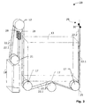
- FIG. 2 A first embodiment of a lift according to The invention is shown in FIG. 2 in a schematic perspective view shown.
- a machine room Elevator system 20 shown comprising a lift shaft or "without a box”.
- the present invention relates to a machine room less Elevator installation 20, the elevator car 13 and at least a first guide rail 15 for vertically guiding the Elevator car 13 includes.
- the first guide rail 15 is shown in Fig. 2 only by a dashed line.
- It two support means 22 are provided, which are substantially parallel to each other.
- the front suspension means with 22.1 and the rear suspension means 22.2 where this for better distinction is necessary.
- At the cabin side End of the support means 22 are the same in the first area Tragstofffixand 29 via a rocker 30 at the Guide rail 15 fixed.
- Each of the support means 22.1 and 22.2 undermines the elevator car 13, wraps around a Traction sheave 12, which before a drive (not in Fig.
- the suspension element 22 carries the counterweight 18 in that the support means 22 to counterweight rollers 21 revolve and at the counterweight end in the Area second support means fixed points 28 are fixed.
- the Slinging of the elevator car 13 takes place at the shown embodiment with Kabinentragrollen 17.1 and Guide rollers 17.2, which are each designed in pairs.
- the said rocker device 30 has two arms and is indicated in Fig. 2 only schematically. It is mechanical like that attached to the guide rail 15 that a rocking motion the rocking device 30 is possible about an axis in the Substantially perpendicular to the guide rail 15 extends. At Each of the two arms of the rocker 30 is ever one the suspension center points provided.
- the rocker device 30 allows for uneven load on the two suspension elements 22.1 and 22.2 a rocking motion by a length compensation is done automatically. Is it coming to a Tragstoffbruch one of the support means, so the luffing device 30 suddenly loaded unbalanced what a Rocking movement of the rocker 30 in one direction caused.
- This rocking motion can either by means of a Button or a non-contact switch detected be used to interrupt the driving of the elevator system, or the luffing device 30 can mechanically into a Speed limiter intervene to stop a brake trigger. It may also alternatively or additionally Warning signal to be triggered. More details on this will be described later.
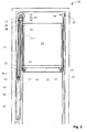
- FIG. 3 remove Details of a similar embodiment are shown in FIG. 3 remove.
- a machine room Elevator system 20 shown.
- the reference numeral 11 is a Lift shaft marked in which a drive 10 with Traction sheave (s) 12, the elevator car 13 via a pair arranged support means 22 moves up and down.
- the Drive 10 together with traction sheave (s) 12 sits laterally above the elevator car 13 on one of the guide rails 15, the is arranged to the left of the elevator car 13.
- Another Guide rail 15 is located to the right of the elevator car 13.
- At the elevator car 13 are guide shoes 14th provided to the elevator car 13 vertically along the two guide rails 15 to lead.
- the drive 10 has an on a traction sheave shaft 25th acting drive shaft 24, which is parallel to the counterweight side Wall 13.1 of the elevator car 13 aligned is and carries at least one traction sheave 26.
- the drive 10 and the traction sheave shaft 25 with at least one Traction sheave 12 are mounted on a machine carrier 23, located on the two counterweight guide rails 18.1 supported and mechanically connected to these. It is also possible on the drive 10 and the above elements or to be attached to the guide rail 15, the left of the elevator car 13 is arranged. Alternatively you can Drive 10 and the said elements on the counterweight guide rails 18.1 and the guide rails 15 supported be.
- a brake unit 27 be arranged, the braking of the elevator car 13th allows.
- the brake unit 27 is in Fig. 3 only by Dashed lines indicated because they are behind the drive 10th sitting.
- Fig. 3 are the counterweight-side suspension element fixing points 28 of the suspension element 22 attached in the area below the machine carrier 23.
- this attachment is done by means of screws about which the position of the support means end individually can be adjusted. This can be done an adjustment be that allows the luffing device 30 in a predefined location, for example a horizontal position too bring.
- the two support means 22 (22.1 and 22.2) are substantially parallel to each other.
- the suspension elements 22 run along the left Side wall 13.1 of the elevator car 13 down and then at least partially around the cabin roll 17.1 around guided. This type of suspension is called as Underslinging.
- the support means 22 are guided upward, where each of the Supporting means 22 in the area of the cabin-side suspension element fixing points 29 is attached to an arm of a rocker 30.
- suspension is synonymous with any kind of To understand ropes and means that are suitable for Elevator car 13 and the counterweight 18 to carry and to move.
- the suspension means are Flat or V-ribbed belt. It may be related to the invention but also steel or plastic ropes with round cross-section used as a suspension element.
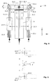
- Fig. 4 is a specific embodiment of the inventive Rocker 30 shown.
- the rocker device 30 includes a first arm 30.1 and a second arm 30.2.
- these arms 30.1 and 30.2 are preferably not necessarily symmetrical with respect to a rotation axis 30.3 arranged, in the example shown perpendicular to the plane of the drawing runs.
- the axis of rotation 30.3 is on or on the Guide rail 15 stored.
- Each of the two arms 30.1 and 30.2 has attachment points 30.4 and 30.5, the Attachment of the support means 22.1 and 22.2 serve. Important is only that the attachment points 30.4 and 30.5 are arranged symmetrically with respect to the axis of rotation 30.3.
- the attachment of the Support means 22.1 and 22.2 by means of rods 31.1, 31.2, the in the upper part are designed as eyelets 31.3, 31.4.
- the Eyelets 31.3, 31.4 sit on axles 30.7, 30.8, or the like. They are clamping or screwing 22.3 and 22.4 provided, which are the ends of flat or V-ribbed belts 22.1, 22.2 record and fix.
- the support means to V-ribbed belts 22.1, 22.2 as you can see from the parallel can recognize running lines, which the ribs of the To represent belts.
- the round bars 31.1, 31.2 can be designed as threaded spindles to turn by turning Round bars 31.1, 31.2 the position of the arms of the rocking device 30 to be able to adjust.
- the rocker 30 is also in a position shown that it occupies when the support means 22.1 shorter is as the support means 22.2. This position of the rocker 30 is shown by dashed lines.
- the Unequal length of the support means 22.1, and 22.2 results a rocking motion about the axis 30.3, the ⁇ through the angle can be quantified.
- On the guide rail 15 can optionally a stop 36 for the arms of the rocking device 30th be provided.
- the luffing device 30 Laterally next to the luffing device 30 is an optional Device 32 shown in a rocking motion, the over exceeds a limit, the elevator system 20 turns off and / or the elevator car (13) brakes and / or a warning signal triggers.
- This device 32 will be simplified herein referred to as a limiting device. It can become Example to act a button, the two contacts electrically conductive connects, as long as the rocker device 30 is in an angular range that is smaller than ⁇ ⁇ . If the luffing device 30 leaves the angle range ⁇ ⁇ above or below - for example, due to different Wearer or when breaking a suspension - so the button interrupts the electrically conductive connection.
- the button can be part of the usual be present at elevators existing safety circuit.
- a non-contact can also Switch can be used.
- a tilt sensor or tilt switch used in the area of the rocker 30 so is arranged that when a too large Deflection of the rocker 30 triggered a reaction becomes.
- FIG. 5 shows a section that runs through an inventive rocker device 30 and guide rail 15.
- Fig. 5 serves to explain the geometric arrangement of a preferred embodiment.
- the luffing device 30 is arranged and designed so that it is supported on the centroid P of the guide rail 15 so that a connecting line X between two support means extends through this centroid.
- the distance a of the two axes 30.7 and 30.8, which symbolize the force application positions of the support means, from the point P is the same for both arms 30.1 and 30.2.
- the two axes 30.7 and 30.8 are indicated in Fig. 5 by dashed lines.
- the connection of the support means with the arms of the rocking device is designed according to the invention so that it allows at least small rotational movements.
- the luffing device can perform corresponding rocking movements of the different support means elongation.
- the rotational movement can be achieved by the attachment of the support means on the arms 30.1, 30.2 of the luffing device 30 by means of eyelets 31.3, 31.4 and axes 30.7, 30.8 is executed.
- secondary rockers can also be provided, which are connected via axes with the arms 30.1, 30.2 of the luffing device. These secondary rockers can perform small rocking movements with respect to the rocker.
- Another embodiment is characterized in that the rods 31.1, 31.2 are flexible and connected at their upper ends in the region of the eyelets fixed to the arms of the Wippvorraum. The flexibility of the rods 31.1, 31.2 gives the necessary freedom of movement.
- FIG. 6 Shown in Fig. 6 is a schematic arrangement which, similar to the limiting device 32, triggers a response when the rocking motion exceeds a threshold. If the deflection of the arms of the luffing device 40 by large differences in length of the support means 42.1, 42.2 or due to a Tragstoffbruchs exceeds a certain limit, the blocking pendulum 47 of a pendulum speed limiter 43 of known type is forced into blocking position by the arm 41. Such speed limiters 43 are used to limit the speed of elevator cars.
- a closed rope 44 namely a so-called speed limiter rope is used as auxiliary rope.
- This speed limiter cable 44 travels around a pulley 45 of the speed limiter 43 mounted in the elevator shaft at the top and around a tension pulley mounted at the bottom in the hoistway (not shown in FIG. 6).
- the overspeed governor 44 is connected to the elevator car via a catcher trip lever 46, which is not shown in FIG. If the speed of the elevator car exceeds a certain limit speed, then the pulley 45 of the speed limiter 43 and with it the speed limiter cable 44 are blocked by the blocking pendulum 47, whereby the braked speed limiter cable 44 actuates the safety gear release lever 46 moving with the moving elevator car so that triggers a mounted on the elevator car safety device triggers.
- the safety gear can be triggered when the deflection of the arms of the rocker 40 by large differences in length of the support means 42.1, 42.2 or due to a Tragstoffbruchs exceeds a certain limit.
- the arm 41 of the rocker 40 actuates either directly or via a lever 50, the blocking pendulum 47 and thereby causes the above-described blocking of the speed limiter 43 and the triggering of the safety brake.
- the rocker 40 is supported on the guide rail 48 from.
- the speed limiter 43 can be carried by the guide rail 48 via a mechanical connection 49.
- the limiting device 32 (FIG. 4) can also be electrical, e.g. via a solenoid, the speed limiter Trigger according to FIG. 6.
- the luffing device 30 stored so that their rocking movements slightly damped are.
- short load variations e.g. by Vibrations of the elevator car 13 are damped.
- means may be provided which are known as Stop for the luffing device 30; 40 serve.
- Stop for the luffing device 30; 40 serve.
- adjustable stop screws 60 serving this purpose shown.
- Embodiments with 4, 6 or more support means 52.1 - 52.4 can be designed so that in each case two of the suspension means 52.1, 52.2 and 52.3, 52.4 in pairs on a luffing device 55.1 and 55.2 are attached. Two such rockers 55.1 and 55.2 are then together again at a parent Rocker 55.3 suspended, as shown schematically in Fig. 7 is shown. The entire rocking device is supported turn on the guide rail 51 from.
- Another embodiment is characterized in that the support means also on the counterweight side at the are fixed there guide rail.
Priority Applications (6)
| Application Number | Priority Date | Filing Date | Title |
|---|---|---|---|
| EP03405591A EP1510493A1 (fr) | 2003-08-12 | 2003-08-12 | Système d'ascenseur avec attache d'extrémité de câble dépendant de la charge |
| ES04017606.7T ES2565231T3 (es) | 2003-08-12 | 2004-07-26 | Instalación de ascensor con punto fijo de elemento de suspensión de cargas dependiente de la carga |
| EP04017606.7A EP1508545B1 (fr) | 2003-08-12 | 2004-07-26 | Système d'ascenseur avec attache d'extrémité de câble dépendant de la charge |
| BR0403216-0A BRPI0403216A (pt) | 2003-08-12 | 2004-08-12 | Instalação de elevador com um dispositivo oscilador com ponto de fixação de dispositivos de suporte e dispositivo oscilador para uso em uma instalação de elevador |
| CNB2004100574746A CN1304265C (zh) | 2003-08-12 | 2004-08-12 | 具有摆杆装置的电梯设备 |
| US10/916,790 US20050045432A1 (en) | 2003-08-12 | 2004-08-12 | Elevator installation with a rocker device as support means fixing point and rocker device for use in an elevator installation |
Applications Claiming Priority (1)
| Application Number | Priority Date | Filing Date | Title |
|---|---|---|---|
| EP03405591A EP1510493A1 (fr) | 2003-08-12 | 2003-08-12 | Système d'ascenseur avec attache d'extrémité de câble dépendant de la charge |
Publications (1)
| Publication Number | Publication Date |
|---|---|
| EP1510493A1 true EP1510493A1 (fr) | 2005-03-02 |
Family
ID=34089783
Family Applications (1)
| Application Number | Title | Priority Date | Filing Date |
|---|---|---|---|
| EP03405591A Withdrawn EP1510493A1 (fr) | 2003-08-12 | 2003-08-12 | Système d'ascenseur avec attache d'extrémité de câble dépendant de la charge |
Country Status (5)
| Country | Link |
|---|---|
| US (1) | US20050045432A1 (fr) |
| EP (1) | EP1510493A1 (fr) |
| CN (1) | CN1304265C (fr) |
| BR (1) | BRPI0403216A (fr) |
| ES (1) | ES2565231T3 (fr) |
Families Citing this family (6)
| Publication number | Priority date | Publication date | Assignee | Title |
|---|---|---|---|---|
| US7293670B2 (en) * | 2004-09-08 | 2007-11-13 | Mhe Technologies, Inc. | Upper block |
| WO2007149079A1 (fr) * | 2006-06-21 | 2007-12-27 | Otis Elevator Company | Régulateur pour système d'ascenseur |
| ES2294944B1 (es) * | 2006-09-25 | 2009-02-16 | Orona S. Coop | Elemento de suspension y traccion para aparatos elevadores y aparato elevador. |
| KR20090122934A (ko) * | 2007-03-12 | 2009-12-01 | 인벤티오 아게 | 승강기 |
| CN102887415B (zh) * | 2012-09-14 | 2015-09-30 | 保定申菱机电有限公司 | 电梯 |
| CN105173992A (zh) * | 2015-10-27 | 2015-12-23 | 苏州中远电梯有限公司 | 一种可提高安全性能的电梯 |
Citations (2)
| Publication number | Priority date | Publication date | Assignee | Title |
|---|---|---|---|---|
| EP0987212A2 (fr) * | 1998-09-14 | 2000-03-22 | Kabushiki Kaisha Toshiba | Ascenseur de type à traction avec attaches pour solidariser les extrémités de câble aux rails de guidage |
| EP1123891A2 (fr) * | 2000-02-09 | 2001-08-16 | Otis Elevator Company | Attache pour extrêmité de câble d'ascenseur |
Family Cites Families (14)
| Publication number | Priority date | Publication date | Assignee | Title |
|---|---|---|---|---|
| US620364A (en) * | 1899-02-28 | rolff | ||
| US122846A (en) * | 1872-01-16 | Improvement in hoisting apparatus | ||
| US1963706A (en) * | 1933-05-01 | 1934-06-19 | Neve Peter La | Self-equalizing suspension tackle for elevator cars |
| US3386722A (en) * | 1965-05-27 | 1968-06-04 | Richard W. Brooks | Carriage for supporting lances in steel making operations |
| JP2790615B2 (ja) * | 1994-10-20 | 1998-08-27 | 三菱電機株式会社 | エレベータ用調速機 |
| DE19507628A1 (de) * | 1995-03-04 | 1996-09-05 | Dover Europ Aufzuege Gmbh | Aufzug |
| US6256841B1 (en) * | 1998-12-31 | 2001-07-10 | Otis Elevator Company | Wedge clamp type termination for elevator tension member |
| SG75168A1 (en) * | 1998-05-08 | 2000-09-19 | Inventio Ag | Hydraulic elevator |
| FI109468B (fi) * | 1998-11-05 | 2002-08-15 | Kone Corp | Vetopyörähissi |
| JP2002167137A (ja) * | 2000-11-29 | 2002-06-11 | Toshiba Corp | エレベータ |
| JP4085577B2 (ja) * | 2001-01-18 | 2008-05-14 | フジテック株式会社 | ロープ端末装置 |
| US6659231B2 (en) * | 2002-03-12 | 2003-12-09 | Inventio Ag | Self-balancing synchronization assembly for a hydraulic elevator |
| IL157277A (en) * | 2002-09-05 | 2007-12-03 | Inventio Ag | Elevator and method of arranging the motor of an elevator |
| JP2005263490A (ja) * | 2004-03-15 | 2005-09-29 | Inventio Ag | 大荷重用エレベータ |
-
2003
- 2003-08-12 EP EP03405591A patent/EP1510493A1/fr not_active Withdrawn
-
2004
- 2004-07-26 ES ES04017606.7T patent/ES2565231T3/es active Active
- 2004-08-12 US US10/916,790 patent/US20050045432A1/en not_active Abandoned
- 2004-08-12 BR BR0403216-0A patent/BRPI0403216A/pt not_active IP Right Cessation
- 2004-08-12 CN CNB2004100574746A patent/CN1304265C/zh not_active Expired - Fee Related
Patent Citations (2)
| Publication number | Priority date | Publication date | Assignee | Title |
|---|---|---|---|---|
| EP0987212A2 (fr) * | 1998-09-14 | 2000-03-22 | Kabushiki Kaisha Toshiba | Ascenseur de type à traction avec attaches pour solidariser les extrémités de câble aux rails de guidage |
| EP1123891A2 (fr) * | 2000-02-09 | 2001-08-16 | Otis Elevator Company | Attache pour extrêmité de câble d'ascenseur |
Also Published As
| Publication number | Publication date |
|---|---|
| CN1590268A (zh) | 2005-03-09 |
| ES2565231T3 (es) | 2016-04-01 |
| US20050045432A1 (en) | 2005-03-03 |
| BRPI0403216A (pt) | 2005-05-24 |
| CN1304265C (zh) | 2007-03-14 |
Similar Documents
| Publication | Publication Date | Title |
|---|---|---|
| EP0554712B1 (fr) | Système de tension d'un câble pour ascenseurs | |
| EP2421785B1 (fr) | Surveillance de l'état de fonctionnement de matériaux de support dans une installation d'ascenseur | |
| EP1700811B1 (fr) | Ascenseur | |
| EP2560909B1 (fr) | Surveillance de l'état de fonctionnement d'éléments de support dans une installation d'ascenseur | |
| EP1953108B1 (fr) | Ascenseur et procédé de surveillance de cet ascenseur | |
| EP2227429B1 (fr) | Système d'ascenseur à deux cabines d'ascenseur | |
| DE19906073C2 (de) | Vorrichtung zum Verhindern unkontrollierter Beschleunigungen eines Fahrkorbs einer Aufzugsanlage | |
| WO2012004268A1 (fr) | Surveillance des moyens de suspension dans une installation d'ascenseur | |
| EP2928805B1 (fr) | Ascenseur à biplan avec distance intercabine réglable | |
| WO2012055747A1 (fr) | Installation d'ascenseur | |
| DE112013006610B4 (de) | Aufzugsvorrichtung | |
| EP1508545B1 (fr) | Système d'ascenseur avec attache d'extrémité de câble dépendant de la charge | |
| EP1510493A1 (fr) | Système d'ascenseur avec attache d'extrémité de câble dépendant de la charge | |
| EP3119713A1 (fr) | Ascenseur équipé d'un dispositif de tension de câble de compensation | |
| EP1918238B1 (fr) | Ascenseur doté de deux cabines superposées dans une gaine | |
| EP3227216A1 (fr) | Installation d'ascenseur | |
| EP1457453A1 (fr) | Dispositif pour la surveillance des câbles d'ascenseur | |
| EP0739850B1 (fr) | Limitation des oscillations des éléments de compensation pour ascenseurs | |
| DE10319731B4 (de) | Aufzug | |
| DE102013215901A1 (de) | Servicelift | |
| EP3020674B1 (fr) | Ascenseur de service | |
| DE1295150B (de) | Aufzug mit einer Sperreinrichtung an der Unterseilrolle | |
| EP4271640A1 (fr) | Dispositif de suspension et son utilisation dans un système d'ascenseur, et procédé | |
| EP3124423A1 (fr) | Dispositif de suspension de support dote d'un dispositif a bascule a deux niveaux ayant des bras de retenus inferieurs longs pour un ascenseur | |
| DE10034511C1 (de) | Maschinenraumloser Seilaufzug |
Legal Events
| Date | Code | Title | Description |
|---|---|---|---|
| PUAI | Public reference made under article 153(3) epc to a published international application that has entered the european phase |
Free format text: ORIGINAL CODE: 0009012 |
|
| STAA | Information on the status of an ep patent application or granted ep patent |
Free format text: STATUS: THE APPLICATION HAS BEEN WITHDRAWN |
|
| 17P | Request for examination filed |
Effective date: 20040519 |
|
| AK | Designated contracting states |
Kind code of ref document: A1 Designated state(s): AT BE BG CH CY CZ DE DK EE ES FI FR GB GR HU IE IT LI LU MC NL PT RO SE SI SK TR |
|
| AX | Request for extension of the european patent |
Extension state: AL LT LV MK |
|
| 18W | Application withdrawn |
Effective date: 20050204 |