EP1510415A1 - Insassenbeinschutzvorrichtung - Google Patents
Insassenbeinschutzvorrichtung Download PDFInfo
- Publication number
- EP1510415A1 EP1510415A1 EP04005306A EP04005306A EP1510415A1 EP 1510415 A1 EP1510415 A1 EP 1510415A1 EP 04005306 A EP04005306 A EP 04005306A EP 04005306 A EP04005306 A EP 04005306A EP 1510415 A1 EP1510415 A1 EP 1510415A1
- Authority
- EP
- European Patent Office
- Prior art keywords
- flaps
- occupant
- airbag
- tear lines
- cover section
- Prior art date
- Legal status (The legal status is an assumption and is not a legal conclusion. Google has not performed a legal analysis and makes no representation as to the accuracy of the status listed.)
- Granted
Links
- 238000005452 bending Methods 0.000 abstract description 10
- 230000001154 acute effect Effects 0.000 description 1
- 230000006698 induction Effects 0.000 description 1
- 238000012986 modification Methods 0.000 description 1
- 230000004048 modification Effects 0.000 description 1
Images


Classifications
-
- B—PERFORMING OPERATIONS; TRANSPORTING
- B60—VEHICLES IN GENERAL
- B60R—VEHICLES, VEHICLE FITTINGS, OR VEHICLE PARTS, NOT OTHERWISE PROVIDED FOR
- B60R21/00—Arrangements or fittings on vehicles for protecting or preventing injuries to occupants or pedestrians in case of accidents or other traffic risks
- B60R21/02—Occupant safety arrangements or fittings, e.g. crash pads
- B60R21/16—Inflatable occupant restraints or confinements designed to inflate upon impact or impending impact, e.g. air bags
- B60R21/20—Arrangements for storing inflatable members in their non-use or deflated condition; Arrangement or mounting of air bag modules or components
- B60R21/205—Arrangements for storing inflatable members in their non-use or deflated condition; Arrangement or mounting of air bag modules or components in dashboards
- B60R21/206—Arrangements for storing inflatable members in their non-use or deflated condition; Arrangement or mounting of air bag modules or components in dashboards in the lower part of dashboards, e.g. for protecting the knees
-
- B—PERFORMING OPERATIONS; TRANSPORTING
- B60—VEHICLES IN GENERAL
- B60R—VEHICLES, VEHICLE FITTINGS, OR VEHICLE PARTS, NOT OTHERWISE PROVIDED FOR
- B60R21/00—Arrangements or fittings on vehicles for protecting or preventing injuries to occupants or pedestrians in case of accidents or other traffic risks
- B60R21/02—Occupant safety arrangements or fittings, e.g. crash pads
- B60R21/16—Inflatable occupant restraints or confinements designed to inflate upon impact or impending impact, e.g. air bags
- B60R21/20—Arrangements for storing inflatable members in their non-use or deflated condition; Arrangement or mounting of air bag modules or components
- B60R21/215—Arrangements for storing inflatable members in their non-use or deflated condition; Arrangement or mounting of air bag modules or components characterised by the covers for the inflatable member
- B60R21/2165—Arrangements for storing inflatable members in their non-use or deflated condition; Arrangement or mounting of air bag modules or components characterised by the covers for the inflatable member characterised by a tear line for defining a deployment opening
-
- B—PERFORMING OPERATIONS; TRANSPORTING
- B60—VEHICLES IN GENERAL
- B60R—VEHICLES, VEHICLE FITTINGS, OR VEHICLE PARTS, NOT OTHERWISE PROVIDED FOR
- B60R21/00—Arrangements or fittings on vehicles for protecting or preventing injuries to occupants or pedestrians in case of accidents or other traffic risks
- B60R2021/003—Arrangements or fittings on vehicles for protecting or preventing injuries to occupants or pedestrians in case of accidents or other traffic risks characterised by occupant or pedestian
- B60R2021/0039—Body parts of the occupant or pedestrian affected by the accident
- B60R2021/0051—Knees
-
- B—PERFORMING OPERATIONS; TRANSPORTING
- B60—VEHICLES IN GENERAL
- B60R—VEHICLES, VEHICLE FITTINGS, OR VEHICLE PARTS, NOT OTHERWISE PROVIDED FOR
- B60R21/00—Arrangements or fittings on vehicles for protecting or preventing injuries to occupants or pedestrians in case of accidents or other traffic risks
- B60R21/02—Occupant safety arrangements or fittings, e.g. crash pads
- B60R21/16—Inflatable occupant restraints or confinements designed to inflate upon impact or impending impact, e.g. air bags
- B60R21/23—Inflatable members
- B60R21/231—Inflatable members characterised by their shape, construction or spatial configuration
- B60R2021/23169—Inflatable members characterised by their shape, construction or spatial configuration specially adapted for knee protection
Definitions
- the present invention relates to an occupant-leg protection device for protecting lower legs of an occupant from hitting against an interior panel in front of a seat in a vehicle collision.
- An occupant-leg protection device for protecting lower legs of an occupant from hitting against an interior panel in front of a seat in a collision of a high-speed moving object such as a vehicle includes a device mainly including an airbag disposed inside the interior panel (a space on the reverse side of the interior panel), a gas generator for inflating the airbag, and a cover for covering the airbag at an ordinary time (when the high-speed moving object such as the vehicle does not encounter a collision).
- the airbag is arranged inside the interior panel in a folded state, and the cover is attached so as to cover the folded airbag therewith.
- the gas generator is operated to inject gas which is in turn supplied to the airbag so that the airbag is rapidly inflated.
- the cover With inflation of the airbag, the cover is opened so as to allow the airbag to expand outside the interior panel and to inflate and develop between the interior panel and occupant lower legs for protecting the occupant lower legs from hitting against the interior panel.
- JP-A-2003-40069 discloses that the cover is provided with a break-predestined section downwardly U-shaped and extending along lateral edges and the upper edge of the cover while being provided with a hinge extending along the lower edge of the cover.
- the cover breaks along the break-predestined section so as to form a flap.
- the flap is downward rotated and opened about the hinge as a rotation axis so that the airbag develops in front of the occupant lower legs.
- An occupant-leg protection device includes an airbag arranged inside a member disposed in front of a seat; a gas generator for inflating the airbag; and a cover covering the airbag so as to open when the airbag is inflated, wherein the cover is provided with a break-predestined section so as to break along the break-predestined section for forming flaps when the airbag is inflated, and wherein the break-predestined section forms a plurality of the laterally arranged flaps.
- the break-predestined section may preferably form four or more laterally arranged flaps.
- the break-predestined section may also form a flap to be upward opened and a flap to be downward opened.
- each flap weighs small. Therefore, each kinetic momentum is small so that the impact applied to an occupant leg becomes small when the rotating flap hits at the occupant leg.
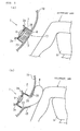
- An occupant-leg protection device 1 includes a container-like retainer 2 having an opening formed on the front surface (surface adjacent to an occupant), an airbag 4 arranged and folded inside the retainer 2, and a gas generator 6 for inflating the airbag 4, and is covered with an interior panel 10 in which the front opening of the retainer 2 is located in front of a front passenger seat.
- Reference numeral 2a denotes a bracket fixed to a vehicle body member (not shown).
- a section covering the front opening of the retainer 2 is a cover region (referred to as a cover section below) 11 to be opened when the airbag 4 inflates.
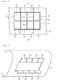
- the cover section 11, as shown in Fig. 2, includes break-predestined sections that are a center tear line 12 formed in the vicinity of the vertical intermediate position of the cover section 11 and extending in the lateral direction (vehicle width direction), first and second vertical tear lines 13 and 14 extending in the vertical direction respectively along left and right sides of the cover section 11, and third, fourth, and fifth vertical tear lines 15, 16, and 17 extending in the vertical direction in parallel with each other between the first and second vertical tear lines 13 and 14.
- the first and second vertical tear lines 13 and 14 are connected to left and right ends of the center tear line 12 in the vicinities of the intermediate positions thereof, respectively.
- the vicinities of the intermediate positions of the third to fifth vertical tear lines 15 to 17 intersect at positions in the halfway of the center tear line 12, respectively.
- tear lines 12 to 17 are concave grooves formed on the reverse surface of the cover section 11, and are fragile sections with a small panel thickness along therewith. Therefore, when the airbag 4 is inflated, the cover section 11 breaks along these tear lines 12 to 17 by a pressure force from the airbag 4 so as to open toward an occupant in flap shapes.
- the cover section 11 is zoned by these tear lines 12 to 17 into four above regions and four below, eight regions in total. Therefore, when the cover section 11 breaks along these tear lines 12 to 17 during the inflation of the airbag, eight flaps 18, 19, 20, 21, 22, 23, 24, and 25 are formed in total.
- each of the flaps 18 to 25 is provided with a hinge (bending induction part) 26 or 27 formed on the base.
- the hinges 26 and 27 are linear fragile concave grooves, with a depth smaller than those of the tear lines 12 to 17, extending in the horizontal direction so as to respectively connect the upper ends and the lower ends of the vertical tear lines 13 to 17 together.
- the flaps 18 to 25 are pressurized by the airbag 4 inflating toward the surface of the interior panel 10 so as to open toward an occupant by bending from the hinges on the bases.
- the flaps 18, 19, 20, and 21 are upward rotated about the upper hinge 26 as a rotation axis while the flaps 22, 23, 24, and 25 are downward rotated about the lower hinge 27 as a rotation axis.
- the gas generator 6 is operated to inject gas which in turn starts inflating the airbag 4 so as to open the cover section 11 of the interior panel 10 for pushing the inflating airbag 4 outside the surface of the interior panel 10. Then, as shown in Fig. 1(b), the inflated airbag 4 receives occupant legs so as to prevent the occupant legs from hitting against the interior panel 10.
- the cover section 11 is broken into eight flaps that are the four flaps 18 to 21, which are upward opened from the vicinity of the center in the vertical direction, and the four flaps 22 to 25, which are downward opened therefrom. Accordingly, each of the flaps 18 to 25 weighs small so as to reduce each kinetic momentum at the beginning of opening. Therefore, in the case where the occupant legs are located extremely close to the interior panel 10 when an occupant is seated forward on the front passenger seat 8 or when an occupant is seated on the front passenger seat 8 which is moved toward the vehicle front, for example, the impact applied to the occupant leg becomes small even when any of the flaps 18 to 25 hits at the occupant leg along the opening way.
- the structures such as the shape of the cover section, the number and shape of the flaps formed by breaking of the cover section during the airbag inflation, and the opening direction, are not limited to the structures shown in Figs. 1 to 3, and various modifications may be made.
- a cover section 11A shown in Fig. 4 includes break-predestined sections that are a horizontal tear line 30 extending in the lateral direction along the upper side of the cover section 11A, first and second vertical tear lines 31 and 32 extending in the vertical direction respectively along left and right sides of the cover section 11A, and third, fourth, and fifth vertical tear lines 33, 34, and 35 extending in the vertical direction in parallel with each other between the first and second vertical lines 31 and 32.
- the first and second vertical tear lines 31 and 32 are connected to left and right ends of the horizontal tear line 30 at the upper ends thereof, respectively.
- the upper ends of the third to fifth vertical tear lines 33 to 35 are connected to the halfway of the horizontal tear line 30.
- a hinge 36 which is a concave groove shallower than those of these tear lines, extends in the horizontal direction along the lower side of the cover section 11A so as to connect the lower ends of the vertical tear lines 31 to 35 together.
- the cover section 11A is zoned by these tear lines 30 to 35 and the hinge 36 into four regions. Therefore, the cover section 11A breaks along these tear lines 30 to 35 by a pressure force from the airbag 4 during the inflation of the airbag 4 (not shown in Fig. 4) so as to form four flaps 37, 38, 39, and 40 in total. These flaps 37 to 40 are downward opened by bending from the hinge 36 at the respective lower ends.
- each of the flaps 37 to 40 weighs small so as to also reduce each kinetic momentum at the beginning of opening. Therefore, the impact applied to the occupant leg becomes small even when any of the flaps 37 to 40 hits at the occupant leg along the opening way.
- a cover section 11B shown in Fig. 5 includes break-predestined sections that are a center tear line 50 formed in the vicinity of the vertical intermediate position of the cover section 11B and extending in the lateral direction, first and second vertical tear lines 51 and 52 extending in the substantially vertical direction respectively on left and right both sides of the center tear line 50, and third, fourth, and fifth vertical tear lines 53, 54, and 55 extending in the vertical direction in parallel with each other between the first and second vertical tear lines 51 and 52.
- the first and second vertical tear lines 51 and 52 are connected, in the vicinities of the intermediate positions thereof, to the left and right ends of the center tear line 50, respectively.
- the vicinities of the intermediate positions of the third to fifth vertical tear lines 53 to 55 intersect at positions in the halfway of the center tear line 50, respectively.
- the upper half section and the lower half section extend in directions intersecting with the center tear line 50 from the vicinity of each intermediate position, respectively, while any intersecting angle ⁇ of each section with the center tear line 50 is an obtuse angle.
- the remaining third to fifth vertical tear lines 53 to 55 extend linearly in the vertical direction so as to orthogonally cross the center tear line 50.
- the third to fifth vertical tear lines 53 to 55 may extend in directions intersecting with the center tear line 50.
- hinges 56 and 57 which are concave grooves shallower than those of these vertical tear lines, are provided to extend in the horizontal direction respectively along the upper and lower sides of the cover section 11B.
- hinges 58 and 58 which are shallow concave grooves identical to those of the hinges 56 and 57, are provided to extend in the vertical direction respectively along the left and right sides of the cover section 11B so as to respectively connect the upper and lower ends of the first vertical tear line 51 together and the upper and lower ends of the second vertical tear line 52 together.
- the cover section 11B is zoned by these tear lines 50 to 55 and the hinges 56 to 58 into ten regions in total. Therefore, the cover section 11B breaks along these tear lines 50 to 55 by a pressure force from the airbag 4 during the inflation of the airbag 4 (not shown in Fig. 5) so as to form ten flaps 59, 60, 61, 62, 63, 64, 65, 66, 67, and 68 in total.
- the flaps 59 to 62 are upward opened by bending from the hinge 56 at the respective upper ends while the flaps 63 to 66 are downward opened by bending from the hinge 57 at the respective lower ends. Also, the flaps 67 and 68 are laterally opened by bending from the left hinge 58 and the right hinge 58, respectively.
- each of the flaps 59 to 68 weighs small so as to also reduce each kinetic momentum at the beginning of opening. Therefore, the impact applied to the occupant leg becomes small even when any of the flaps 59 to 68 hits at the occupant leg along the opening way.
- a cover section 11C shown in Fig. 6 includes break-predestined sections that are a center tear line 70 formed in the vicinity of the vertical intermediate position of the cover section 11C and extending in the lateral direction, first and second vertical tear lines 71 and 72 extending in the substantially vertical direction respectively on left and right both ends of the center tear line 70, and third, fourth, and fifth vertical tear lines 73, 74, and 75 extending in the vertical direction in parallel with each other between the first and second vertical tear lines 71 and 72.
- the first and second vertical tear lines 71 and 72 are connected, in the vicinities of the intermediate positions thereof, to the left and right ends of the center tear line 70, respectively.
- the vicinities of the intermediate positions of the third to fifth vertical tear lines 73 to 75 intersect at positions in the halfway of the center tear line 70, respectively.
- the upper half section and the lower half section extend in directions intersecting with the center tear line 70 from the vicinity of each intermediate position, respectively, while any intersecting angle ⁇ of each section with the center tear line 50 is an acute angle.
- the remaining third to fifth vertical tear lines 73 to 75 extend linearly in the vertical direction so as to orthogonally cross the center tear line 70.
- the third to fifth vertical tear lines 73 to 75 may extend in directions intersecting with the center tear line 70.
- hinges 76 and 77 which are concave grooves shallower than those of these vertical tear lines, are provided to extend in the horizontal direction respectively along the upper and lower sides of the cover section 11C.
- the cover section 11C is zoned by these tear lines 70 to 75 and the hinges 76 to 77 into eight regions in total. Therefore, the cover section 11C breaks along these tear lines 70 to 75 by a pressure force from the airbag 4 during the inflation of the airbag 4 (not shown in Fig. 6) so as to form eight flaps 78, 79, 80, 81, 82, 83, 84, and 85 in total.
- the flaps 78 to 81 are upward opened by bending from the hinge 76 at the respective upper ends while the flaps 82 to 85 are downward opened by bending from the hinge 77 at the respective lower ends.
- each of the flaps 78 to 85 weighs small so as to also reduce each kinetic momentum at the beginning of opening. Therefore, the impact applied to the occupant leg becomes small even when any of the flaps 78 to 85 hits at the occupant leg along the opening way.
- the cover section covering the front opening of the retainer is integrally formed with the interior panel; alternatively, the cover may be provided separately from the interior panel.
Landscapes
- Engineering & Computer Science (AREA)
- Mechanical Engineering (AREA)
- Air Bags (AREA)
Applications Claiming Priority (2)
| Application Number | Priority Date | Filing Date | Title |
|---|---|---|---|
| JP2003301608 | 2003-08-26 | ||
| JP2003301608A JP2005067466A (ja) | 2003-08-26 | 2003-08-26 | 乗員脚部保護装置 |
Publications (2)
| Publication Number | Publication Date |
|---|---|
| EP1510415A1 true EP1510415A1 (de) | 2005-03-02 |
| EP1510415B1 EP1510415B1 (de) | 2007-05-16 |
Family
ID=34101174
Family Applications (1)
| Application Number | Title | Priority Date | Filing Date |
|---|---|---|---|
| EP04005306A Expired - Lifetime EP1510415B1 (de) | 2003-08-26 | 2004-03-05 | Insassenbeinschutzvorrichtung |
Country Status (5)
| Country | Link |
|---|---|
| US (1) | US20050046158A1 (de) |
| EP (1) | EP1510415B1 (de) |
| JP (1) | JP2005067466A (de) |
| CN (1) | CN100377927C (de) |
| DE (1) | DE602004006473T2 (de) |
Cited By (7)
| Publication number | Priority date | Publication date | Assignee | Title |
|---|---|---|---|---|
| EP1637409A3 (de) * | 2004-09-21 | 2006-11-02 | Mitsubishi Jidosha Kogyo Kabushiki Kaisha | Kraftfahrzeugseitentür mit einem Airbag |
| EP2022684A4 (de) * | 2006-05-15 | 2010-02-17 | Toyota Motor Co Ltd | Airbagvorrichtung zum knieschutz, verfahren zum entfalten einer airbagvorrichtung zum knieschutz und fahrzeug |
| EP2322390A4 (de) * | 2008-09-04 | 2012-01-25 | Toyota Motor Co Ltd | Knie-airbagvorrichtung für ein fahrzeug |
| EP2192007A4 (de) * | 2007-09-18 | 2012-12-12 | Toyota Motor Co Ltd | Knieairbag für ein fahrzeug |
| WO2014072154A1 (de) * | 2012-11-07 | 2014-05-15 | Autoliv Development Ab | Kraftfahrzeug mit einem knie-gassackmodul |
| FR3007346A1 (fr) * | 2013-06-24 | 2014-12-26 | Visteon Global Tech Inc | Dispositif de fermeture de logement pour airbag |
| CN111532233A (zh) * | 2019-02-07 | 2020-08-14 | 现代摩比斯株式会社 | 防止乘客之间碰撞的安全气囊装置 |
Families Citing this family (18)
| Publication number | Priority date | Publication date | Assignee | Title |
|---|---|---|---|---|
| JP4589855B2 (ja) * | 2005-07-26 | 2010-12-01 | 本田技研工業株式会社 | 衝突物保護装置 |
| DE102006033895A1 (de) * | 2006-07-18 | 2008-01-31 | Takata-Petri Ag | Airbagmodul für ein Kraftfahrzeug |
| JP2008174210A (ja) * | 2006-12-19 | 2008-07-31 | Mazda Motor Corp | 車両用脚部保護エアバッグ装置 |
| JP4815339B2 (ja) * | 2006-12-21 | 2011-11-16 | ダイキョーニシカワ株式会社 | エアバッグドア部付き車両用内装品 |
| JP4546515B2 (ja) * | 2007-11-27 | 2010-09-15 | 本田技研工業株式会社 | 車両用エアバッグ装置 |
| JP4580998B2 (ja) * | 2008-03-13 | 2010-11-17 | 本田技研工業株式会社 | 車両用エアバッグ装置のカバー体 |
| JP5456288B2 (ja) * | 2008-09-08 | 2014-03-26 | オートリブ ディベロップメント エービー | エアバッグドア構造 |
| WO2010050019A1 (ja) * | 2008-10-29 | 2010-05-06 | トヨタ自動車株式会社 | 車両用ニーエアバッグ装置 |
| US7946611B2 (en) * | 2009-03-31 | 2011-05-24 | Tk Holdings Inc. | Knee airbag module |
| JP2010285021A (ja) * | 2009-06-10 | 2010-12-24 | Toyota Motor Corp | 車両用エアバッグ装置 |
| JP5182256B2 (ja) * | 2009-08-28 | 2013-04-17 | トヨタ自動車株式会社 | 車両用ニーエアバッグ装置 |
| US8500161B2 (en) * | 2010-03-31 | 2013-08-06 | Tk Holdings Inc. | Knee airbag |
| US8567814B2 (en) * | 2011-05-19 | 2013-10-29 | Faurecia Interior Systems, Inc. | Patterned weakening of airbag coverings |
| CN102745166A (zh) * | 2012-03-09 | 2012-10-24 | 浙江吉利汽车研究院有限公司 | 一种车用侧面安全气囊 |
| DE102014224478A1 (de) * | 2014-12-01 | 2016-06-02 | Bayerische Motoren Werke Aktiengesellschaft | Airbaganordnung |
| CN107697019A (zh) * | 2017-09-11 | 2018-02-16 | 奇瑞汽车股份有限公司 | 一种汽车行人小腿保护装置 |
| US10829007B2 (en) * | 2018-01-26 | 2020-11-10 | Adient Engineering and IP GmbH | Active long track cover |
| DE102018202086B4 (de) * | 2018-02-12 | 2026-03-26 | Aumovio Germany Gmbh | Vorrichtung zum Insassenschutz eines Fahrzeugs sowie Fahrzeug mit einer solchen Vorrichtung |
Citations (3)
| Publication number | Priority date | Publication date | Assignee | Title |
|---|---|---|---|---|
| JPS58110338A (ja) * | 1981-12-23 | 1983-06-30 | Toyota Motor Corp | 自動車のエアバツグ格納部構造 |
| US5084122A (en) * | 1986-07-28 | 1992-01-28 | Toyo Tire & Rubber Co., Ltd. | Method for manufacturing an air bag attachment structure |
| JP2003040069A (ja) * | 2001-05-21 | 2003-02-13 | Toyoda Gosei Co Ltd | 膝保護用エアバッグ装置 |
Family Cites Families (16)
| Publication number | Priority date | Publication date | Assignee | Title |
|---|---|---|---|---|
| US5082310A (en) * | 1989-11-06 | 1992-01-21 | Tip Engineering Group, Inc. | Arrangement for providing an air bag deployment opening |
| US5335935A (en) * | 1992-08-31 | 1994-08-09 | Plastic Mold Technology Incorporated | Air bag cover/molded article with integral cover layer of leather |
| DE4229379C2 (de) * | 1992-09-03 | 1996-03-28 | Daimler Benz Ag | Abdeckung für das Gaskissen einer Aufprallschutzvorrichtung für Fahrzeuginsassen |
| US5342088A (en) * | 1993-10-05 | 1994-08-30 | Tip Engineering Group | Deployment door patterns for an air bag safety system |
| US5580083A (en) * | 1995-10-02 | 1996-12-03 | Davidson Textron Inc. | Air bag cover with seamless interface tear seam and method and apparatus for producing same |
| JP3078741B2 (ja) * | 1996-01-09 | 2000-08-21 | トヨタ自動車株式会社 | 助手席用エアバッグカバー |
| DE19646548C2 (de) * | 1996-10-31 | 1998-08-27 | Sommer Allibert Lignotock Gmbh | Innenverkleidungsteil für Kraftfahrzeuge mit Airbag-Ausrüstung |
| US5730460A (en) * | 1996-11-22 | 1998-03-24 | General Motors Corporation | Air bag cover |
| US5893581A (en) * | 1996-11-22 | 1999-04-13 | General Motors Corporation | Air bag cover |
| ES2324321T3 (es) * | 1997-03-26 | 2009-08-04 | Toyota Jidosha Kabushiki Kaisha | Elemento interior que presenta una seccion de puerta de airbag para su utilizacion en vehiculos, y su procedimiento de moldeado. |
| DE29913741U1 (de) * | 1999-08-06 | 1999-12-16 | TRW Automotive Safety Systems GmbH & Co. KG, 63743 Aschaffenburg | Abdeckung für einen Gassack eines Fahrzeuginsassen-Rückhaltesystems |
| US6761375B2 (en) * | 2000-04-26 | 2004-07-13 | Sanko Gosei Kabushiki Kaisha | Structure of reinforcement plate member used in automobile airbag apparatus |
| US6715789B2 (en) * | 2001-05-21 | 2004-04-06 | Toyoda Gosei Co., Ltd. | Knee protecting airbag device |
| DE10130715A1 (de) * | 2001-06-26 | 2002-12-19 | Breed Automotive Tech | Abdeckung für ein Airbagmodul |
| US6793238B2 (en) * | 2002-03-20 | 2004-09-21 | Autoliv Asp, Inc. | Airbag covers for multi-axis deployment |
| US6848705B2 (en) * | 2002-03-20 | 2005-02-01 | Autoliv Asp, Inc. | Airbag cover with multi-axis deployment |
-
2003
- 2003-08-26 JP JP2003301608A patent/JP2005067466A/ja active Pending
-
2004
- 2004-03-05 EP EP04005306A patent/EP1510415B1/de not_active Expired - Lifetime
- 2004-03-05 DE DE602004006473T patent/DE602004006473T2/de not_active Expired - Lifetime
- 2004-04-08 US US10/820,015 patent/US20050046158A1/en not_active Abandoned
- 2004-05-26 CN CNB2004100459733A patent/CN100377927C/zh not_active Expired - Fee Related
Patent Citations (3)
| Publication number | Priority date | Publication date | Assignee | Title |
|---|---|---|---|---|
| JPS58110338A (ja) * | 1981-12-23 | 1983-06-30 | Toyota Motor Corp | 自動車のエアバツグ格納部構造 |
| US5084122A (en) * | 1986-07-28 | 1992-01-28 | Toyo Tire & Rubber Co., Ltd. | Method for manufacturing an air bag attachment structure |
| JP2003040069A (ja) * | 2001-05-21 | 2003-02-13 | Toyoda Gosei Co Ltd | 膝保護用エアバッグ装置 |
Non-Patent Citations (2)
| Title |
|---|
| PATENT ABSTRACTS OF JAPAN vol. 0072, no. 17 (M - 245) 27 September 1983 (1983-09-27) * |
| PATENT ABSTRACTS OF JAPAN vol. 2003, no. 06 3 June 2003 (2003-06-03) * |
Cited By (10)
| Publication number | Priority date | Publication date | Assignee | Title |
|---|---|---|---|---|
| EP1637409A3 (de) * | 2004-09-21 | 2006-11-02 | Mitsubishi Jidosha Kogyo Kabushiki Kaisha | Kraftfahrzeugseitentür mit einem Airbag |
| US7338072B2 (en) | 2004-09-21 | 2008-03-04 | Mitsubishi Jidosha Kogyo Kabushi Kaisha | Side door for vehicle |
| EP2022684A4 (de) * | 2006-05-15 | 2010-02-17 | Toyota Motor Co Ltd | Airbagvorrichtung zum knieschutz, verfahren zum entfalten einer airbagvorrichtung zum knieschutz und fahrzeug |
| EP2192007A4 (de) * | 2007-09-18 | 2012-12-12 | Toyota Motor Co Ltd | Knieairbag für ein fahrzeug |
| EP2322390A4 (de) * | 2008-09-04 | 2012-01-25 | Toyota Motor Co Ltd | Knie-airbagvorrichtung für ein fahrzeug |
| WO2014072154A1 (de) * | 2012-11-07 | 2014-05-15 | Autoliv Development Ab | Kraftfahrzeug mit einem knie-gassackmodul |
| FR3007346A1 (fr) * | 2013-06-24 | 2014-12-26 | Visteon Global Tech Inc | Dispositif de fermeture de logement pour airbag |
| US10625702B2 (en) | 2013-06-24 | 2020-04-21 | Visteon Global Technologies, Inc. | Closing device for a housing for an airbag |
| CN111532233A (zh) * | 2019-02-07 | 2020-08-14 | 现代摩比斯株式会社 | 防止乘客之间碰撞的安全气囊装置 |
| CN111532233B (zh) * | 2019-02-07 | 2022-07-08 | 现代摩比斯株式会社 | 防止乘客之间碰撞的安全气囊装置 |
Also Published As
| Publication number | Publication date |
|---|---|
| US20050046158A1 (en) | 2005-03-03 |
| JP2005067466A (ja) | 2005-03-17 |
| CN100377927C (zh) | 2008-04-02 |
| DE602004006473T2 (de) | 2007-09-27 |
| EP1510415B1 (de) | 2007-05-16 |
| DE602004006473D1 (de) | 2007-06-28 |
| CN1590166A (zh) | 2005-03-09 |
Similar Documents
| Publication | Publication Date | Title |
|---|---|---|
| EP1510415B1 (de) | Insassenbeinschutzvorrichtung | |
| EP2635463B1 (de) | Mittelseitenairbag zwischen armlehne und sitz | |
| EP1466792B1 (de) | Beinschutzeinrichtung für Fahrzeuginsassen | |
| EP1544054B1 (de) | Fahrzeug mit einem Insassenbeinschutzsystem und einem Kniegassack | |
| EP1775176B1 (de) | Eine Nut ausbildender Gassack | |
| US6315324B1 (en) | Air bag tether construction | |
| US7942440B2 (en) | Channel and diffuser airbag | |
| US20160355152A1 (en) | External airbag system | |
| KR20020013907A (ko) | 자동차용의 팽창가능한 에어백 | |
| US6502852B2 (en) | Air bag cover with internal hinge configuration | |
| US20100244409A1 (en) | Airbag | |
| US12351121B2 (en) | Seat airbag device for vehicle | |
| KR102609538B1 (ko) | 드라이버 에어백 장치 | |
| EP1541427B1 (de) | Knieairbag und Schutzsystem für die Beine des Passagiers | |
| US5286055A (en) | Modular cover for an air bag assembly | |
| JPWO2020174892A1 (ja) | エアバッグ装置 | |
| JP4715030B2 (ja) | 乗員脚部保護装置 | |
| US6733032B2 (en) | Air bag cover assembly | |
| JP4478830B2 (ja) | エアバッグドア | |
| KR102780780B1 (ko) | 차량의 에어백 쿠션 | |
| KR102593658B1 (ko) | 차량용 파사이드 에어백 장치 | |
| US11891011B1 (en) | Airbag tear seam | |
| JP2007523006A (ja) | エアバッグ装置 | |
| KR102840709B1 (ko) | 에어백 장치 | |
| KR200193451Y1 (ko) | 조수석 에어백 커버 구조 |
Legal Events
| Date | Code | Title | Description |
|---|---|---|---|
| PUAI | Public reference made under article 153(3) epc to a published international application that has entered the european phase |
Free format text: ORIGINAL CODE: 0009012 |
|
| AK | Designated contracting states |
Kind code of ref document: A1 Designated state(s): AT BE BG CH CY CZ DE DK EE ES FI FR GB GR HU IE IT LI LU MC NL PL PT RO SE SI SK TR |
|
| AX | Request for extension of the european patent |
Extension state: AL LT LV MK |
|
| 17P | Request for examination filed |
Effective date: 20050818 |
|
| AKX | Designation fees paid |
Designated state(s): DE FR GB SE |
|
| GRAP | Despatch of communication of intention to grant a patent |
Free format text: ORIGINAL CODE: EPIDOSNIGR1 |
|
| GRAS | Grant fee paid |
Free format text: ORIGINAL CODE: EPIDOSNIGR3 |
|
| RIN1 | Information on inventor provided before grant (corrected) |
Inventor name: ABE, KAZUHIRO |
|
| GRAA | (expected) grant |
Free format text: ORIGINAL CODE: 0009210 |
|
| AK | Designated contracting states |
Kind code of ref document: B1 Designated state(s): DE FR GB SE |
|
| REG | Reference to a national code |
Ref country code: GB Ref legal event code: FG4D |
|
| REF | Corresponds to: |
Ref document number: 602004006473 Country of ref document: DE Date of ref document: 20070628 Kind code of ref document: P |
|
| REG | Reference to a national code |
Ref country code: SE Ref legal event code: TRGR |
|
| ET | Fr: translation filed | ||
| PLBE | No opposition filed within time limit |
Free format text: ORIGINAL CODE: 0009261 |
|
| STAA | Information on the status of an ep patent application or granted ep patent |
Free format text: STATUS: NO OPPOSITION FILED WITHIN TIME LIMIT |
|
| 26N | No opposition filed |
Effective date: 20080219 |
|
| PGFP | Annual fee paid to national office [announced via postgrant information from national office to epo] |
Ref country code: GB Payment date: 20130228 Year of fee payment: 10 Ref country code: FR Payment date: 20130325 Year of fee payment: 10 Ref country code: SE Payment date: 20130312 Year of fee payment: 10 |
|
| PGFP | Annual fee paid to national office [announced via postgrant information from national office to epo] |
Ref country code: DE Payment date: 20140417 Year of fee payment: 11 |
|
| REG | Reference to a national code |
Ref country code: SE Ref legal event code: EUG |
|
| GBPC | Gb: european patent ceased through non-payment of renewal fee |
Effective date: 20140305 |
|
| PG25 | Lapsed in a contracting state [announced via postgrant information from national office to epo] |
Ref country code: SE Free format text: LAPSE BECAUSE OF NON-PAYMENT OF DUE FEES Effective date: 20140306 |
|
| REG | Reference to a national code |
Ref country code: FR Ref legal event code: ST Effective date: 20141128 |
|
| PG25 | Lapsed in a contracting state [announced via postgrant information from national office to epo] |
Ref country code: GB Free format text: LAPSE BECAUSE OF NON-PAYMENT OF DUE FEES Effective date: 20140305 Ref country code: FR Free format text: LAPSE BECAUSE OF NON-PAYMENT OF DUE FEES Effective date: 20140331 |
|
| REG | Reference to a national code |
Ref country code: DE Ref legal event code: R119 Ref document number: 602004006473 Country of ref document: DE |
|
| PG25 | Lapsed in a contracting state [announced via postgrant information from national office to epo] |
Ref country code: DE Free format text: LAPSE BECAUSE OF NON-PAYMENT OF DUE FEES Effective date: 20151001 |