EP1509346B1 - Linear drive metal forming machine - Google Patents
Linear drive metal forming machine Download PDFInfo
- Publication number
- EP1509346B1 EP1509346B1 EP03724748A EP03724748A EP1509346B1 EP 1509346 B1 EP1509346 B1 EP 1509346B1 EP 03724748 A EP03724748 A EP 03724748A EP 03724748 A EP03724748 A EP 03724748A EP 1509346 B1 EP1509346 B1 EP 1509346B1
- Authority
- EP
- European Patent Office
- Prior art keywords
- container body
- forming die
- prime mover
- sidewall
- knockout
- Prior art date
- Legal status (The legal status is an assumption and is not a legal conclusion. Google has not performed a legal analysis and makes no representation as to the accuracy of the status listed.)
- Expired - Lifetime
Links
- 239000002184 metal Substances 0.000 title claims description 48
- 229910052751 metal Inorganic materials 0.000 title claims description 48
- 230000033001 locomotion Effects 0.000 claims description 38
- 238000000034 method Methods 0.000 claims description 36
- 239000012530 fluid Substances 0.000 claims description 8
- 230000005019 pattern of movement Effects 0.000 claims 1
- 230000009467 reduction Effects 0.000 description 18
- 230000008569 process Effects 0.000 description 13
- 238000004519 manufacturing process Methods 0.000 description 10
- 239000000463 material Substances 0.000 description 10
- 238000006073 displacement reaction Methods 0.000 description 8
- 238000011161 development Methods 0.000 description 7
- 230000004048 modification Effects 0.000 description 7
- 238000012986 modification Methods 0.000 description 7
- 230000008901 benefit Effects 0.000 description 5
- 230000008859 change Effects 0.000 description 5
- 238000007493 shaping process Methods 0.000 description 5
- 238000005516 engineering process Methods 0.000 description 4
- 230000004075 alteration Effects 0.000 description 3
- 235000013361 beverage Nutrition 0.000 description 3
- 238000003780 insertion Methods 0.000 description 3
- 230000037431 insertion Effects 0.000 description 3
- 230000002250 progressing effect Effects 0.000 description 3
- 238000004891 communication Methods 0.000 description 2
- 238000007796 conventional method Methods 0.000 description 2
- 230000000694 effects Effects 0.000 description 2
- 238000000605 extraction Methods 0.000 description 2
- 230000001133 acceleration Effects 0.000 description 1
- 230000009471 action Effects 0.000 description 1
- 239000000443 aerosol Substances 0.000 description 1
- 230000005540 biological transmission Effects 0.000 description 1
- 230000007547 defect Effects 0.000 description 1
- 230000001747 exhibiting effect Effects 0.000 description 1
- 150000002739 metals Chemical class 0.000 description 1
- 238000005457 optimization Methods 0.000 description 1
- 230000000704 physical effect Effects 0.000 description 1
- 238000000926 separation method Methods 0.000 description 1
- 238000012360 testing method Methods 0.000 description 1
- 230000008719 thickening Effects 0.000 description 1
- 230000000007 visual effect Effects 0.000 description 1
- 230000037303 wrinkles Effects 0.000 description 1
Images


Classifications
-
- B—PERFORMING OPERATIONS; TRANSPORTING
- B21—MECHANICAL METAL-WORKING WITHOUT ESSENTIALLY REMOVING MATERIAL; PUNCHING METAL
- B21D—WORKING OR PROCESSING OF SHEET METAL OR METAL TUBES, RODS OR PROFILES WITHOUT ESSENTIALLY REMOVING MATERIAL; PUNCHING METAL
- B21D51/00—Making hollow objects
- B21D51/16—Making hollow objects characterised by the use of the objects
- B21D51/26—Making hollow objects characterised by the use of the objects cans or tins; Closing same in a permanent manner
-
- B—PERFORMING OPERATIONS; TRANSPORTING
- B21—MECHANICAL METAL-WORKING WITHOUT ESSENTIALLY REMOVING MATERIAL; PUNCHING METAL
- B21D—WORKING OR PROCESSING OF SHEET METAL OR METAL TUBES, RODS OR PROFILES WITHOUT ESSENTIALLY REMOVING MATERIAL; PUNCHING METAL
- B21D41/00—Application of procedures in order to alter the diameter of tube ends
- B21D41/04—Reducing; Closing
-
- B—PERFORMING OPERATIONS; TRANSPORTING
- B21—MECHANICAL METAL-WORKING WITHOUT ESSENTIALLY REMOVING MATERIAL; PUNCHING METAL
- B21D—WORKING OR PROCESSING OF SHEET METAL OR METAL TUBES, RODS OR PROFILES WITHOUT ESSENTIALLY REMOVING MATERIAL; PUNCHING METAL
- B21D51/00—Making hollow objects
- B21D51/16—Making hollow objects characterised by the use of the objects
- B21D51/26—Making hollow objects characterised by the use of the objects cans or tins; Closing same in a permanent manner
- B21D51/2615—Edge treatment of cans or tins
Definitions
- the present invention generally pertains to the method and apparatus for producing containers and, more particularly, to die necking of such containers (see for example GB-A-2 310 043).
- necking The technology for reducing the open-end portion of a closed end container (necking) has been in existence for over one hundred years.
- the procedure was originally developed for artillery shells, with a larger diameter shell casing being reduced to retain a smaller diameter projectile.
- the process by which this is accomplished today is called die necking.
- the basic concept of necking is to force a typically cylindrical, thin walled metal body or shell at a given diameter and physically push it into a die or series of progressively smaller dies. In this process a reduction in diameter of the open end is realized.
- the primary purpose for a reduced diameter at the open-end is material savings, and thus realized as cost savings.
- the end panel is of a thickness that is on the order of at least twice the thickness of a typical sidewall, as the diameter of the container is reduced, the amount of material necessary for the end panel is reduced by a greater amount.
- the necking operation is performed to bring the opening to a specific diameter to facilitate a standard size valve assembly and eliminate any secondary adaptor that would otherwise be necessary.
- a secondary consideration of reducing the diameter of the end of the container is the reduction in the longitudinal stress exerted on the end of the container. As the cap size is reduced, this stress is reduced and the thickness requirement of the end cap is also reduced.
- the third consideration for diameter reduction is visual. Many aesthetically pleasing shapes can be achieved by necking conventional cylindrical block shapes into tapered geometries and containers that resemble bottles.
- the strength of the can body depends on a number of factors including the Young's modulus and yield stress of the material, the plate thickness and the can diameter. If the practical limit on diameter reduction is exceeded, the material will wrinkle, pleat, pucker or tear at a point inherent to the geometrical characteristics and type of metal being necked.
- the present invention overcomes the disadvantages and limitations of the prior art by providing a method and an apparatus as defined in claims 1 and 11 respectively, using computer numerical control.
- a computational device such as a computer, is used to control the action of a knockout ram and/or a pusher ram in a container die necking apparatus and method.
- the motions of the pusher and the knockout rams are preferably controlled by a prime mover such as a motor, power transmission system, hydraulic system, etc., whose motion is controlled by a computer control system optionally via a displacement feedback loop.
- a prime mover such as a motor, power transmission system, hydraulic system, etc.
- the computer numerical control systems checks the prescribed path that the user enters in for each ram to the displacement feedback loop and makes adjustments to the prime mover accordingly.
- the system preferably uses time as its base.
- linear reciprocal prime movers as used herein we mean a motor or other device that acts in a linear manner to apply force or movement in a desired linear direction without relying on rotary hard cams or the like to advance a knockout element, a container body or a die.
- prime movers include linear drive motors, hydraulic motors, pneumatic motors, or the like.
- prime movers are characterized by greater ranges of linear movement than can be obtained with traditional hard cams. The movement is reciprocal (i.e. can be produced in either direction) and generally highly controllable, despite the application of considerable forces.
- the most preferred prime movers for use in the present invention are linear drive electric motors.
- the method involves introducing a knockout element into the container body through the open end, providing a forming die shaped to reduce the diameter of the sidewall of the container body when the open end of the container body is forced therein to produce a neck portion of reduced diameter on the container body, driving the open end of the container body into the forming die, retracting the knockout element through the neck portion as the neck portion is formed, and removing the container body from the forming die and knockout element.
- the method utilizes at least one linear reciprocal prime mover arranged to create movement or force in the direction of the longitudinal axis of the container body to move the knockout element, or to force the container body into the forming die, or both.
- an apparatus for reducing the diameter of a sidewall of a seamless unitary metal container body having a sidewall, an endwall at one end of the sidewall, an open end at an opposite end of the sidewall, and a longitudinal axis extending between the endwall and the open end.
- the apparatus comprises a knockout element adapted to be inserted into the container body through the open end, a forming die shaped to reduce the diameter of the sidewall of the container body when the open end of the container body is forced therein to produce a neck portion of reduced diameter on the container body, means for driving the open end of the container body into the forming die, means for retracting the knockout element through the neck portion as the neck portion is formed, and means for removing the container body from the forming die and knockout element.
- At least one of the means for driving the open end of the container body into the forming die and the means for retracting the knockout element through the neck portion is a linear reciprocal prime mover arranged to create movement or force in the direction of the longitudinal axis of the container body to move the knockout element, or to force the container body into the forming die, or both.
- the use of linear prime movers under computer numerical control for manipulating thin gauge metal offers a wide variety of advantages over conventional technology and is not limited to die necking.
- the present invention provides a high degree of versatility in forming operations and a capability to change profile shaping and a variety of operating parameters in real time.
- Cam development can be accomplished using the readily adjustable process of the present invention to derive empirical data quickly and efficiently with programmable adjustment of variables such as motion, force and velocity.
- Stroke length can be adjusted by simply dialing in the desired length on the fly and without shutting down operations as opposed to tearing the machine down, removing the cam that determines thrust, retooling the cam, replacing and testing the new stroke to determine if it matches the intended modification and finally to determine if the modification matches the intended result on the cam profile.
- a variety of forming variables and associated ratios can be customized and easily adjusted for individual operations and can be controlled independently for each stage in a multiple stage machine.
- the present invention allows forming operations that require a high degree of variability and precision to be possible. It also allows machinery to be developed which may have been impractical from a development standpoint using current technology.
- the present invention may therefore comprise a method of reducing the diameter of the sidewall at the open end of a seamless unitary metal container body having a sidewall disposed about a longitudinal axis and a unitary endwall at one longitudinal end of the sidewall opposite to the open end comprising: placing the container body with the endwall in communication with a drive segment and the sidewall in communication with a forming segment having a fixed position forming die of curvilinear configuration in longitudinal cross section and located to form a juncture with the original diameter of the sidewall and progressing with further reduction in diameter toward the open end of the container body; driving a knockout ram with a first linear drive motor that produces a reciprocal motion in the longitudinal axis relative to the container; drawing a knockout that is connected to the knockout ram, the knockout disposed to engage an interior surface of the open end of the container and having a substantially uniform reduced diameter corresponding to the reduction in diameter at the curvilinear configuration of the forming die; extending the knockout longitudinally with
- the present invention may also comprise an apparatus for reducing the diameter of a sidewall at the open end of a seamless unitary container body, the sidewall disposed about a longitudinal axis and a unitary endwall at one longitudinal end of the sidewall opposite to the open end comprising: a fixed position forming die of curvilinear configuration in longitudinal cross section and located to form a juncture with the diameter of the sidewall and progressing with further reduction in diameter toward the open end of the container body; a first linear drive motor producing a reciprocal motion in the longitudinal axis relative to the container; a knockout of substantially uniform reduced diameter corresponding to the reduction in diameter at the curvilinear configuration of the forming die, the knockout extending longitudinally from a position outside of the open end of the container to a depth within the container body beyond the juncture with the diameter of the sidewall; a second linear drive motor producing a reciprocal motion in the longitudinal axis relative to the container; a pusher ram connected to a pusher pad which engages
- the present invention may also comprise an apparatus for the development of metal container manufacturing equipment comprising: an apparatus for reducing the diameter of a sidewall at the open end of a seamless unitary container body, the sidewall disposed about a longitudinal axis and a unitary endwall at one longitudinal end of the sidewall opposite to the open end comprising; a fixed position forming die of curvilinear configuration in longitudinal cross section and located to form a juncture with the diameter of the sidewall and progressing with further reduction in diameter toward the open end of the container body; a first linear drive motor producing a reciprocal motion in the longitudinal axis relative to the container; a knockout of substantially uniform reduced diameter corresponding to the reduction in diameter at the curvilinear configuration of the forming die, the knockout extending longitudinally from a position outside of the open end of the container to a depth within the container body beyond the juncture with the diameter of the sidewall; a second linear drive motor producing a reciprocal motion in the longitudinal axis relative to the container; a
- the present invention has numerous advantages over prior art. These include a high degree of versatility in forming operations and a capability to change operating parameters on the fly. Variables such as motion, force and velocity are programmable and highly adjustable at anytime during the forming stroke. In combination with this variability the present invention allows for alteration of the programming in real time, and thus, modifications to the metal forming can be accomplished rapidly and without shutting down or retooling the production equipment. This real time alteration of metal forming allows the apparatus to be utilized as a development tool to set manufacturing parameters on production machines that do not possess such variability.
- the forming variables and associated ratios can be customized and easily adjusted for individual operations and can be controlled independently for each stage in a multiple stage machine. This can be accomplished on the "push" side of the forming operation and also on the "pull side” with the same or different forces. These additional motions can be used for multiple necking stages or any other operation that require linear motion such as expandable mandrels or for performance of other operations (i.e., bottom piercing etc.).
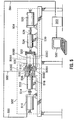
- Figure 1 of the drawings discloses a schematic illustration of one embodiment of the overall system and apparatus of the present invention.
- the apparatus can be viewed as including a forming segment 102 and a drive segment 104 (illustrated within dotted lines) that together carry out operations on a seamless unitary metal container body 106 to achieve a reduction in the diameter of the sidewall 106A of the body, an operation also known as die necking.
- Die necking is initiated by the stroke of a first linear motor 116, which is preferably a linear drive motor, acting as a prime mover.
- the first linear motor 116 generates an inwardly directed longitudinal force on a knockout ram 114 that is transmitted to a knockout element 110 (often referred to simply as a "knockout").
- the knockout ram 114 is secured by a knockout ram bushing/die retainer 112 which allows the knockout ram to experience linear motion in the direction of the longitudinal axis 106B of the metal container 106.
- the ram bushing/die retainer 112 also holds and retains a forming die 108 through which the knockout ram 114 and knockout element 110 extend.
- a similar second linear motor 128 is provided in the drive segment 104 and it generates an inwardly directed linear force on a pusher ram 126 that extends through a pusher ram bushing 124 to a pusher pad 122.
- the pusher ram bushing 124 secures the pusher ram 126 and allows the pusher ram to experience linear motion in the direction of the longitudinal axis 106 B of the container body 106.
- the pusher pad consequently exerts force on a closed end wall 106C of the container body 106.
- the first linear motor 116 is initiated to extend and insert the knockout element 110 inside the open-ended metal container 106 beyond a point where a reduction in the diameter of the sidewall will occur.
- the second linear motor 128 transmits a longitudinal force through pusher ram 126 to pusher pad 122.
- the metal container body 106 is consequently driven into and contacts a shaped inner forming surface 108A of the forming die 108 from the receiver end.
- Air (or other gas) under pressure is introduced into the interior of the container body through a channel 120 in knockout element 110 to pressurize the container body 106 in order to maintain its structural integrity in the radial direction during the necking operation.
- Figure 2 of the drawings discloses a more detailed schematic illustration of one embodiment of the die necking operation of the present invention.
- the die necking reduction of the diameter
- the first linear motor 216 generates a longitudinal force that is transmitted to a knockout element 210.
- the knockout element 210 is extended and inserted inside the open-ended metal container body 206 beyond a point where a reduction in the diameter of the sidewall will occur.
- a second linear motor 228 transmits a longitudinal force to a pusher pad 222.
- An open end 206D of the metal container body 206 is driven into and contacts the inner forming surface 208A of a forming die 208 from the receiver end.
- Air under pressure is introduced into the interior of the container body 206 through a channel 220 passing through the knockout element 210 and is utilized to pressurize the container body 206 to maintain its structural integrity in the radial direction during the necking operation.
- these die necking processes reduce the container diameter by a few millimeters in each operation. If a greater reduction is attempted, the material undergoes a hoop buckling failure known as "pleating."
- the use of the knockout element helps to prevent this failure.
- the profiles of the forming die and the knockout element match each other, so that the gap between them is about 1.03 to 1.5 times the material thickness. This is sufficient to permit the material to pass through with slight thickening, but will not permit the material to pleat.
- Figure 3 of the drawings discloses a more detailed schematic illustration of one embodiment of the die necking operation on the sidewall of a seamless unitary metal container body.
- a metal container 306 with an initial container diameter 334 is pushed into a forming die 308 and applied force from a linear motor (not shown) is transmitted through the body of the container by the container side wall 306A.
- the container sidewall 306A conforms to the shape of the die forming surface 308A and is prevented from pleating by the knockout element 310.
- the container sidewall 306A is shaped in the necked portion of the container 306E from an initial container diameter 334 to a final container diameter 336.
- the maximum force that can be applied to form the necked portion of the container 306E is limited by the strength of the container body 306. If the necking force exceeds the strength of the container body then the necking will cease and the container will be crushed.
- the present invention allows substantial variability not only on the "push” side of the forming operation but also on the “pull” side.
- the pull side is driven by a linear motor that retracts or removes the knockout element 310 from the metal container 306 as the container sidewall 306A conforms to the die forming surface 308A.
- the pull of the knockout element 310 during the push phase of the forming operation assists in drawing the open end 306D of the container sidewall 306A into the forming die 308 and in maintaining proper wall thickness and shape over the necked portion of the container 306E. It is the force and the velocity of the push and pull, as well as their ratios to one another, that determine the ability and precision with which the apparatus is able to shape the metal container body 306.
- FIG. 4 of the drawings discloses a detailed schematic illustration of one embodiment of the die necking operation of the present invention.
- a star wheel assembly 400 is utilized to facilitate the automated insertion and extraction of metal containers 406 from the metal forming apparatus.
- Pre-necked containers 406 are loaded into a chute 440 which is supported by the chute mount 444.
- the containers are stacked and oriented side-to-side awaiting insertion to the star wheel assembly 400 at a star wheel insertion point 442.
- the star wheel assembly indexes by rotating clockwise 45 degrees (in this particular embodiment).
- the die necking operation as described in the previous drawings in performed at a star wheel necking point 446 where the metal container aligns longitudinally with the linear motors and forming die assembly (not shown) as previously described.
- the necked metal container is indexed within the star wheel assembly 400 and continues in a clockwise manner to a point where it is removed from the star wheel assembly 400 at a star wheel extraction point 448.
- the finished container 406' is collected in a pick up gutter 450 which is supported by a pick up gutter mount 452.
- the disclosed invention allows the relative motion of the pusher and knockout element to be capable of a highly variable velocity (push/pull) ratio throughout the neck forming operation. In this manner the velocity ratio (push/pull) can be varied for the individual necking stages and through an individual stroke.
- a microprocessor driven controller By including a microprocessor driven controller, the forces, velocities and respective ratios can all be independently programmable and highly adjustable at anytime during the forming stroke.
- the forming forces described within the aforementioned examples are also programmable and highly adjustable anytime during the forming stroke. They can be customized and adjusted for individual operations and adjusted independently for each stage in a multiple stage machine. Connecting linear motors in tandem can also increase these forces to nearly any extent necessary.
- the system is highly applicable in the area of container manufacture development. Modifications to the metal forming can be accomplished rapidly and without shutting down or retooling the production equipment. Container profiles can be developed quickly and easily using these alterations and optimization features. This allows the invention to be utilized as a laboratory or development tool to set manufacturing parameters on production machines containing less sophistication, variability and cost for purposes of mass production.
- the apparatus of the present invention is preferably controlled by a computer control system, optionally by a displacement feedback loop.
- the computer may be used to control the prime movers acting on the pusher and knockout rams, and optionally the supply of pressurized fluid to the interior of the container body.
- the computer may be used to control such variables as the stroke length of the knockout ram and/or the pusher ram, the velocity ratios of the rams, the strip air timing, pressure and pressurization profile, and adjustments for different neck lengths (e.g. by adjusting pin height).
- Such adjustments may be made by modifications of a computer control program (computer numerical control) via a variety of available user interfaces.
- Figure 5 shows apparatus similar to that of Figure 1, with the same reference numerals used to indicate the same elements, except that the numerals begin with a "5" rather than "1".
- Figure 5 additionally shows a computer controller 580 that may be accessed via a monitor and keyboard arrangement 582.
- the computer controller is connected via wires to actuators controlling the motors 528 and 516 and the air supply via channel 520.
- the apparatus includes a displacement feedback loop (not shown), i.e. means for measuring the displacement (or other characteristics) of the knockout and pusher rams and for returning this information to the computer controller 580 so that the information can be compared with the instructions programmed into the controller.
- the computer controller can therefore check the prescribed path that a user enters in for each ram to the displacement feedback loop and makes adjustment to the prime movers accordingly.
- the system preferably uses time as its base.
- the system may use a desired velocity ratio (i.e. the ratio of the knockout velocity relative to the pusher velocity), which may be held constant or variable, and then the computer controller may determine what path the knockout element or pusher should follow to satisfy the velocity ratio.
- a further alternative way of establishing differential motion between the pusher and knockout is to measure the pusher load or the load that the prime mover sees on the pusher side.
- the load is then used in the feedback loop to control the acceleration, velocity, and/or the displacement ratios between the pusher and knockout rams so that the machine minimizes the load, thus minimizing the load placed on the container being necked.
- It may be necessary to compensate for the load due to the air pressure that is used to strip the container body from the forming die in the apparatus. Just before the container is necked, the container is filled with air at pressure greater than atmospheric pressure. This compensation may be accomplished by using the load in the feedback loop only during the neck forming periods of the machine cycle and/or by measuring the pressure load throughout the cycle and accounting for it.
- the feed back loop mentioned above may be used to minimize the load that is applied to a container body during the necking operation.
- the retraction of the knockout element can be detected and controlled to reduce the force necessary to cause the necking as the container body is forced into the forming die.
- the knockout element helps to draw the container body into the forming die as it shapes the necked portion, thus enabling the pushing force on the container body to be reduced.
- the computer controller can be used to sense and control these respective forces to apply the minimum forces required to achieve proper necking.
- pin height is the distance between the pusher pad and the shaping die and it can be adjusted using the computer controller to control the prime movers using the displacement feedback loops to provide the desired setting input by the user.
- a locking system may then be used to "fix” the adjustment to ensure that it does not change during the course of operation.
- container bodies of differing size may be accommodated by equipment of one kind.
- a variation of this is to use the computer control system that adjusts the pin height to also move during the necking process to provide velocity ratios other than those inherently built into a hard cam system.
- the computer controller may be used to slow down the flow of air to the interior of the container body when a certain pressure has been reached. Air slowly leaks from the container around the knockout element so a continual flow or air into the container body is required to compensate for this. However, if an excessive flow of air is maintained after optimal pressure has been reached, more air merely leaks around the knockout element and costs are increased by the resulting air flow losses.
- the computer By providing a pressure sensor in the container body, e.g. on the knockout element, the computer can be notified when the pressure has reached the optimum value and a valve may be adjusted by the computer controller to minimize the air flow necessary to maintain the desired pressure.
- strip air timing The way in which the air flow is controlled during the necking operation is referred to as strip air timing.
- the computer controller can be used to adjust the strip air timing when adjusting neck profiles in order to provide the air flow at the right time.
- the pressure may also be optimized to allow for the buildup of air so that maximum pressure is reached when needed in order to reduce neck defects and provide the force necessary to strip the container body from the forming die.
- the apparatus of the present invention has infinitely adjustable pusher and knockout ram motion, infinitely adjustable velocity ratios, infinitely adjustable strip air timing, pressure and pressurization profiles, simple adjustments for different neck lengths (by adjusting stroke and pin heights), with simple adjustment for containers of different heights (by adjusting the pin height).
- These adjustments are made to take effect via modifications of the computer control program and are made possible by using at least one linear reciprocal and controllable prime mover.
- the apparatus of the present invention preferably has infinitely adjustable prime movers in both the forming segment and the drive segment, this is not essential.
- a conventional hard cam arrangement may be provided in one of these segments with a reciprocal prime mover in the other.
- the term "hard cam” refers to a physical cam (hardware as opposed to software) of the conventional kind that, upon rotation, causes a longitudinal movement of the pusher ram or knockout ram.
- the hard cam may move the pusher or knockout ram that has a stroke length sufficient to be able to neck container bodies with neck lengths, container heights and diameters that would be within the expected range, while using a computer controlled reciprocal linear prime mover on the other ram.
- hard cams may be used to move both the pusher and the knockout rams, providing stroke lengths sufficient to neck containers with neck lengths, can heights and diameters that would be within an expected range.
- a computer controlled reciprocal linear prime mover may be used to control the pin height between the pusher side relative to the die/knockout side of the machine and to lock the distances in so that there would be no movement during necking.
- the separation between the two sides need not be locked relative to one another, using the computer controlled system to obtain the effect of different velocity ratios between the pusher and knockout rams.
- the invention may be used to form a flexible neck profile machine.
- one set of tooling is designed in such a way that it may be used to neck containers with vastly different neck profiles without the need of all new tooling. In this case, only a few new tools would be required most likely at the beginning and ending stages of the neck tooling progression.
Landscapes
- Engineering & Computer Science (AREA)
- Mechanical Engineering (AREA)
- Shaping Metal By Deep-Drawing, Or The Like (AREA)
- Blow-Moulding Or Thermoforming Of Plastics Or The Like (AREA)
- Fuel-Injection Apparatus (AREA)
- Mounting, Exchange, And Manufacturing Of Dies (AREA)
Applications Claiming Priority (3)
| Application Number | Priority Date | Filing Date | Title |
|---|---|---|---|
| US38586502P | 2002-06-03 | 2002-06-03 | |
| US385865P | 2002-06-03 | ||
| PCT/CA2003/000807 WO2003101642A1 (en) | 2002-06-03 | 2003-05-30 | Linear drive metal forming machine |
Publications (2)
| Publication Number | Publication Date |
|---|---|
| EP1509346A1 EP1509346A1 (en) | 2005-03-02 |
| EP1509346B1 true EP1509346B1 (en) | 2006-09-20 |
Family
ID=29712218
Family Applications (1)
| Application Number | Title | Priority Date | Filing Date |
|---|---|---|---|
| EP03724748A Expired - Lifetime EP1509346B1 (en) | 2002-06-03 | 2003-05-30 | Linear drive metal forming machine |
Country Status (12)
| Country | Link |
|---|---|
| US (1) | US7073365B2 (enExample) |
| EP (1) | EP1509346B1 (enExample) |
| JP (1) | JP2005528221A (enExample) |
| KR (1) | KR100967743B1 (enExample) |
| CN (1) | CN1293958C (enExample) |
| AU (1) | AU2003229215A1 (enExample) |
| BR (1) | BR0311543B1 (enExample) |
| CA (1) | CA2486517C (enExample) |
| DE (1) | DE60308515T2 (enExample) |
| ES (1) | ES2272986T3 (enExample) |
| RU (1) | RU2320444C2 (enExample) |
| WO (1) | WO2003101642A1 (enExample) |
Families Citing this family (50)
| Publication number | Priority date | Publication date | Assignee | Title |
|---|---|---|---|---|
| US20070051687A1 (en) * | 2005-09-07 | 2007-03-08 | Omnitech International, Inc | Reclosable metal bottle |
| US7644712B2 (en) * | 2005-11-09 | 2010-01-12 | Honeywell International Inc. | Negative pressure conditioning device and forced air furnace employing same |
| US7748375B2 (en) * | 2005-11-09 | 2010-07-06 | Honeywell International Inc. | Negative pressure conditioning device with low pressure cut-off |
| DE102005062860A1 (de) | 2005-12-29 | 2007-07-12 | Robert Bosch Gmbh | Verfahren und Vorrichtung zum Herstellen gebogener Federelemente |
| US8591221B2 (en) | 2006-10-18 | 2013-11-26 | Honeywell International Inc. | Combustion blower control for modulating furnace |
| US20080124667A1 (en) | 2006-10-18 | 2008-05-29 | Honeywell International Inc. | Gas pressure control for warm air furnaces |
| GB0624337D0 (en) * | 2006-12-06 | 2007-01-17 | Crown Packaging Technology Inc | Ram alignment |
| US8096156B2 (en) | 2006-12-22 | 2012-01-17 | Crown Packaging Technology, Inc. | Forming of metal container bodies |
| US8006826B2 (en) * | 2008-03-28 | 2011-08-30 | Crown Packagin Technology, Inc. | Star wheel with vacuum capability for retaining conveyed articles |
| US8601843B2 (en) | 2008-04-24 | 2013-12-10 | Crown Packaging Technology, Inc. | High speed necking configuration |
| US9316413B2 (en) * | 2008-06-11 | 2016-04-19 | Honeywell International Inc. | Selectable efficiency versus comfort for modulating furnace |
| US8448487B2 (en) | 2008-10-16 | 2013-05-28 | The Coca-Cola Company | Vessel forming station |
| US8627697B2 (en) * | 2008-10-16 | 2014-01-14 | The Coca-Cola Company | Method of performing non vessel shaping operations during vessel shaping |
| US8726710B2 (en) * | 2008-10-16 | 2014-05-20 | The Coca-Cola Company | Method of coordinating vessel shape style and decoration style |
| US8381561B2 (en) * | 2008-10-16 | 2013-02-26 | The Coca-Cola Company | Vessel forming production line |
| US9067254B2 (en) * | 2008-10-16 | 2015-06-30 | The Coca-Cola Company | Method of configuring a production line to mass customize shaped vessels |
| US8903528B2 (en) * | 2008-10-16 | 2014-12-02 | The Coca-Cola Company | Remote control and management of a vessel forming production line |
| US8726709B2 (en) * | 2008-10-16 | 2014-05-20 | The Coca-Cola Company | Method of shape forming vessels controlling rotational indexing |
| DE102009048405A1 (de) | 2009-10-06 | 2011-04-07 | Honeywell Technologies S.A.R.L. | Regeleinrichtung für Gasbrenner |
| US8360266B2 (en) * | 2009-11-13 | 2013-01-29 | The Coca-Cola Corporation | Shaped metal vessel |
| US20110113732A1 (en) * | 2009-11-13 | 2011-05-19 | The Coca-Cola Company | Method of isolating column loading and mitigating deformation of shaped metal vessels |
| DE102010010791A1 (de) | 2010-03-09 | 2011-09-15 | Honeywell Technologies Sarl | Mischvorrichtung für einen Gasbrenner |
| WO2012027293A2 (en) | 2010-08-23 | 2012-03-01 | Evergreen Packaging Technology, Llc | Indexing machine with a plurality of workstations |
| US8560127B2 (en) | 2011-01-13 | 2013-10-15 | Honeywell International Inc. | HVAC control with comfort/economy management |
| US8950573B2 (en) * | 2011-07-13 | 2015-02-10 | Tipper Tie, Inc. | Electric motor driven pushers for automated clipping packaging apparatus |
| US8950574B2 (en) | 2011-07-13 | 2015-02-10 | Tipper Tie, Inc. | Automated packaging systems with electric motor driven actuators for compression chambers |
| CN102601199A (zh) * | 2012-02-29 | 2012-07-25 | 苏州经贸职业技术学院 | 一种固定芯模式薄壁管精密旋压缩径装置 |
| CN102699218A (zh) * | 2012-05-17 | 2012-10-03 | 太仓奥科机械设备有限公司 | 气瓶缩口装置 |
| US9596865B2 (en) | 2013-03-11 | 2017-03-21 | Tipper Tie, Inc. | Automated packaging systems with electric motor driven actuators for compression of target product |
| CN104368713A (zh) * | 2013-08-17 | 2015-02-25 | 李明军 | 一种全自动双工位缩径机床 |
| CN103909162B (zh) * | 2014-04-01 | 2016-05-04 | 太仓东青金属制品有限公司 | 一种毛细管缩头机 |
| CN104014676B (zh) * | 2014-06-15 | 2016-06-01 | 太仓东青金属制品有限公司 | 一种毛细管缩头机 |
| CN104690176A (zh) * | 2015-01-28 | 2015-06-10 | 苏州市天星山精密模具有限公司 | 一种模具加工机械用缩口机 |
| US10802459B2 (en) | 2015-04-27 | 2020-10-13 | Ademco Inc. | Geo-fencing with advanced intelligent recovery |
| CN108043990B (zh) * | 2016-01-05 | 2020-05-22 | 苏州斯莱克精密设备股份有限公司 | 一种直线式罐口成形设备 |
| EP3790821B1 (en) | 2018-05-11 | 2025-04-02 | Stolle Machinery Company, LLC | Infeed assembly quick change features |
| US11534817B2 (en) | 2018-05-11 | 2022-12-27 | Stolle Machinery Company, Llc | Infeed assembly full inspection assembly |
| US11208271B2 (en) | 2018-05-11 | 2021-12-28 | Stolle Machinery Company, Llc | Quick change transfer assembly |
| US11117180B2 (en) | 2018-05-11 | 2021-09-14 | Stolle Machinery Company, Llc | Quick change tooling assembly |
| JP7312196B2 (ja) | 2018-05-11 | 2023-07-20 | ストール マシーナリ カンパニー,エルエルシー | 回転マニホールド |
| CN115673132B (zh) | 2018-05-11 | 2026-04-17 | 斯多里机械有限责任公司 | 成型站和缩颈机 |
| JP7331017B2 (ja) | 2018-05-11 | 2023-08-22 | ストール マシーナリ カンパニー,エルエルシー | 駆動アセンブリ |
| CN109013937A (zh) * | 2018-08-13 | 2018-12-18 | 宋丽 | 一种预压紧式汽车空调管加工用的缩口装置 |
| KR102176084B1 (ko) * | 2018-10-04 | 2020-11-09 | 주식회사 두레텍 | 하나 이상의 롤링 축에 동일한 동력원을 전달하는 메카니즘 및 이를 이용하는 탄환 제조장치 및 구동 방법. |
| CN110153214B (zh) * | 2019-05-14 | 2020-11-13 | 中国船舶重工集团公司第七二五研究所 | 一种合金变径管用的成型模具及用其加工变径管的方法 |
| US11420242B2 (en) | 2019-08-16 | 2022-08-23 | Stolle Machinery Company, Llc | Reformer assembly |
| CN110899527B (zh) * | 2019-11-27 | 2021-01-12 | 哈尔滨工业大学 | 一种筒形件缩口装置 |
| CN111482522B (zh) * | 2020-04-10 | 2021-11-26 | 曾怀聪 | 一种铁罐压制防滑纹上料装置 |
| CN111516275B (zh) * | 2020-04-27 | 2022-05-03 | 四川中自科技有限公司 | 一种无扩口导管连接件挤压成型设备 |
| US20240359282A1 (en) * | 2023-04-26 | 2024-10-31 | Stolle Machinery Company, Llc | Photoluminescent tooling, tooling inspection method, and tooling inspection apparatus |
Family Cites Families (15)
| Publication number | Priority date | Publication date | Assignee | Title |
|---|---|---|---|---|
| US4392764A (en) * | 1981-09-18 | 1983-07-12 | Continental Can Company, Inc. | Necked-in container body and apparatus for and method of forming same |
| US4446714A (en) * | 1982-02-08 | 1984-05-08 | Cvacho Daniel S | Methods of necking-in and flanging tubular can bodies |
| SU1412858A1 (ru) * | 1986-10-02 | 1988-07-30 | Всесоюзный научно-исследовательский и конструкторско-технологический институт трубной промышленности | Способ изготовлени горловин баллонов |
| DE3706193A1 (de) * | 1987-02-26 | 1988-09-08 | Langenstein & Schemann Gmbh | Hydraulische kaltfliesspresse |
| JPH02220723A (ja) * | 1989-02-22 | 1990-09-03 | Mitsubishi Metal Corp | 缶胴のくびれ加工方法および加工装置 |
| JPH084863B2 (ja) * | 1991-11-27 | 1996-01-24 | アメリカン ナショナル カン カンパニー | 容器にネックを形成する方法 |
| US5355710A (en) * | 1992-07-31 | 1994-10-18 | Aluminum Company Of America | Method and apparatus for necking a metal container and resultant container |
| RU2043813C1 (ru) * | 1993-05-11 | 1995-09-20 | Акционерное общество открытого типа "Синарский трубный завод" | Устройство для обжатия концов труб |
| CN1154080A (zh) * | 1995-05-13 | 1997-07-09 | 克鲁伯合成材料技术有限公司 | 在圆柱形空心体上形成颈缩和卷边的方法和装置 |
| GB9602282D0 (en) | 1996-02-05 | 1996-04-03 | Newmarket Datasystems Ltd | Apparatus & method for process monitoring |
| US5775161A (en) * | 1996-11-05 | 1998-07-07 | American National Can Co. | Staggered die method and apparatus for necking containers |
| US5755130A (en) * | 1997-03-07 | 1998-05-26 | American National Can Co. | Method and punch for necking cans |
| EP0943422B1 (en) * | 1998-03-16 | 2004-05-19 | Yamada Dobby Co., Ltd. | Slide control device of press |
| JP3818788B2 (ja) * | 1998-03-16 | 2006-09-06 | 株式会社山田ドビー | プレス機のスライド制御装置 |
| JP3732355B2 (ja) * | 1999-04-28 | 2006-01-05 | 株式会社ソディック | プレス機械 |
-
2003
- 2003-05-30 EP EP03724748A patent/EP1509346B1/en not_active Expired - Lifetime
- 2003-05-30 CA CA002486517A patent/CA2486517C/en not_active Expired - Fee Related
- 2003-05-30 AU AU2003229215A patent/AU2003229215A1/en not_active Abandoned
- 2003-05-30 KR KR1020047019588A patent/KR100967743B1/ko not_active Expired - Fee Related
- 2003-05-30 BR BRPI0311543-7A patent/BR0311543B1/pt not_active IP Right Cessation
- 2003-05-30 CN CNB038129132A patent/CN1293958C/zh not_active Expired - Fee Related
- 2003-05-30 JP JP2004508982A patent/JP2005528221A/ja active Pending
- 2003-05-30 RU RU2004137790/02A patent/RU2320444C2/ru not_active IP Right Cessation
- 2003-05-30 ES ES03724748T patent/ES2272986T3/es not_active Expired - Lifetime
- 2003-05-30 US US10/515,552 patent/US7073365B2/en not_active Expired - Fee Related
- 2003-05-30 DE DE60308515T patent/DE60308515T2/de not_active Expired - Lifetime
- 2003-05-30 WO PCT/CA2003/000807 patent/WO2003101642A1/en not_active Ceased
Also Published As
| Publication number | Publication date |
|---|---|
| CN1658986A (zh) | 2005-08-24 |
| KR100967743B1 (ko) | 2010-07-05 |
| WO2003101642A1 (en) | 2003-12-11 |
| EP1509346A1 (en) | 2005-03-02 |
| DE60308515D1 (de) | 2006-11-02 |
| RU2320444C2 (ru) | 2008-03-27 |
| US7073365B2 (en) | 2006-07-11 |
| CA2486517A1 (en) | 2003-12-11 |
| BR0311543B1 (pt) | 2011-10-04 |
| KR20050035520A (ko) | 2005-04-18 |
| CN1293958C (zh) | 2007-01-10 |
| ES2272986T3 (es) | 2007-05-01 |
| DE60308515T2 (de) | 2007-01-18 |
| US20050155404A1 (en) | 2005-07-21 |
| RU2004137790A (ru) | 2005-07-27 |
| AU2003229215A1 (en) | 2003-12-19 |
| JP2005528221A (ja) | 2005-09-22 |
| CA2486517C (en) | 2008-07-29 |
| BR0311543A (pt) | 2005-04-26 |
Similar Documents
| Publication | Publication Date | Title |
|---|---|---|
| EP1509346B1 (en) | Linear drive metal forming machine | |
| US4693108A (en) | Method and apparatus for necking and flanging containers | |
| US7287408B2 (en) | Apparatus and method of producing battery case | |
| US5460026A (en) | Method of and apparatus for the cutting of an opening in a hollow body | |
| US4519232A (en) | Method and apparatus for necking containers | |
| EP0294034B1 (en) | Method of forming box-like frame members | |
| EP2835188B1 (en) | Method and device for manufacturing threaded bottle can | |
| US7107804B2 (en) | Methods of and apparatus for pressure-ram-forming metal containers and the like | |
| AU725180B2 (en) | Method and apparatus for shaping a container | |
| EP1161316B1 (en) | Compressive hydroforming | |
| RU2283200C2 (ru) | Способ и устройство для создания сужения открытого конца контейнера | |
| JPH05504725A (ja) | 冷間変形可能な金属から成る中空体を静液圧変形する方法及び装置 | |
| PL202631B1 (pl) | Sposób formowania pod ciśnieniem pustego metalowego wyrobu | |
| JP2010527791A (ja) | 予備フラップ形成加工を伴う金属包装容器用のスピニング加工方法、及び、予備フラップ形成加工を伴う金属包装容器用のスピニング加工装置 | |
| US20120266644A1 (en) | Device and method for manufacturing a can body for an aerosol can | |
| MXPA97002022A (es) | Metodo y aparato para fabricar latas configuradas | |
| US2751676A (en) | Method of cold working metal | |
| US6009734A (en) | Process and device for manufacturing hollow sections with end-side cross-sectional expansions | |
| EP0101146A1 (en) | Method and apparatus for drawing heavy wall shells | |
| US5653138A (en) | Method and apparatus for forming a necked and flanged part on a hollow cylindrical body | |
| CN212760566U (zh) | 一种卡压管成型设备 | |
| JPH0852528A (ja) | パイプのプレス成形方法およびその装置 | |
| AU756122B2 (en) | Method and apparatus for shaping a container | |
| JP2010023077A (ja) | 金属容器の製造方法および金属容器製造装置 | |
| KR20000020653A (ko) | 테이퍼 로울러 제조장치 및 방법 |
Legal Events
| Date | Code | Title | Description |
|---|---|---|---|
| PUAI | Public reference made under article 153(3) epc to a published international application that has entered the european phase |
Free format text: ORIGINAL CODE: 0009012 |
|
| 17P | Request for examination filed |
Effective date: 20041214 |
|
| AK | Designated contracting states |
Kind code of ref document: A1 Designated state(s): AT BE BG CH CY CZ DE DK EE ES FI FR GB GR HU IE IT LI LU MC NL PT RO SE SI SK TR |
|
| AX | Request for extension of the european patent |
Extension state: AL LT LV MK |
|
| DAX | Request for extension of the european patent (deleted) | ||
| RBV | Designated contracting states (corrected) |
Designated state(s): DE ES FR GB IT |
|
| GRAP | Despatch of communication of intention to grant a patent |
Free format text: ORIGINAL CODE: EPIDOSNIGR1 |
|
| GRAS | Grant fee paid |
Free format text: ORIGINAL CODE: EPIDOSNIGR3 |
|
| RAP1 | Party data changed (applicant data changed or rights of an application transferred) |
Owner name: NOVELIS, INC. |
|
| GRAA | (expected) grant |
Free format text: ORIGINAL CODE: 0009210 |
|
| AK | Designated contracting states |
Kind code of ref document: B1 Designated state(s): DE ES FR GB IT |
|
| PG25 | Lapsed in a contracting state [announced via postgrant information from national office to epo] |
Ref country code: IT Free format text: LAPSE BECAUSE OF FAILURE TO SUBMIT A TRANSLATION OF THE DESCRIPTION OR TO PAY THE FEE WITHIN THE PRESCRIBED TIME-LIMIT;WARNING: LAPSES OF ITALIAN PATENTS WITH EFFECTIVE DATE BEFORE 2007 MAY HAVE OCCURRED AT ANY TIME BEFORE 2007. THE CORRECT EFFECTIVE DATE MAY BE DIFFERENT FROM THE ONE RECORDED. Effective date: 20060920 |
|
| REG | Reference to a national code |
Ref country code: GB Ref legal event code: FG4D |
|
| REF | Corresponds to: |
Ref document number: 60308515 Country of ref document: DE Date of ref document: 20061102 Kind code of ref document: P |
|
| ET | Fr: translation filed | ||
| REG | Reference to a national code |
Ref country code: ES Ref legal event code: FG2A Ref document number: 2272986 Country of ref document: ES Kind code of ref document: T3 |
|
| PLBE | No opposition filed within time limit |
Free format text: ORIGINAL CODE: 0009261 |
|
| STAA | Information on the status of an ep patent application or granted ep patent |
Free format text: STATUS: NO OPPOSITION FILED WITHIN TIME LIMIT |
|
| 26N | No opposition filed |
Effective date: 20070621 |
|
| REG | Reference to a national code |
Ref country code: GB Ref legal event code: 732E Free format text: REGISTERED BETWEEN 20110609 AND 20110615 |
|
| REG | Reference to a national code |
Ref country code: DE Ref legal event code: R082 Ref document number: 60308515 Country of ref document: DE Representative=s name: PATENTANWAELTE WEICKMANN & WEICKMANN, DE Ref country code: DE Ref legal event code: R082 Ref document number: 60308515 Country of ref document: DE Representative=s name: WEICKMANN & WEICKMANN PATENTANWAELTE - RECHTSA, DE Ref country code: DE Ref legal event code: R082 Ref document number: 60308515 Country of ref document: DE Representative=s name: WEICKMANN & WEICKMANN, DE Ref country code: DE Ref legal event code: R082 Ref document number: 60308515 Country of ref document: DE Representative=s name: WEICKMANN & WEICKMANN PATENT- UND RECHTSANWAEL, DE |
|
| REG | Reference to a national code |
Ref country code: FR Ref legal event code: PLFP Year of fee payment: 14 |
|
| REG | Reference to a national code |
Ref country code: FR Ref legal event code: PLFP Year of fee payment: 15 |
|
| REG | Reference to a national code |
Ref country code: FR Ref legal event code: PLFP Year of fee payment: 16 |
|
| PGFP | Annual fee paid to national office [announced via postgrant information from national office to epo] |
Ref country code: IT Payment date: 20190529 Year of fee payment: 17 Ref country code: ES Payment date: 20190620 Year of fee payment: 17 Ref country code: DE Payment date: 20190521 Year of fee payment: 17 |
|
| PGFP | Annual fee paid to national office [announced via postgrant information from national office to epo] |
Ref country code: FR Payment date: 20190522 Year of fee payment: 17 |
|
| PGFP | Annual fee paid to national office [announced via postgrant information from national office to epo] |
Ref country code: GB Payment date: 20190521 Year of fee payment: 17 |
|
| REG | Reference to a national code |
Ref country code: DE Ref legal event code: R119 Ref document number: 60308515 Country of ref document: DE |
|
| GBPC | Gb: european patent ceased through non-payment of renewal fee |
Effective date: 20200530 |
|
| PG25 | Lapsed in a contracting state [announced via postgrant information from national office to epo] |
Ref country code: GB Free format text: LAPSE BECAUSE OF NON-PAYMENT OF DUE FEES Effective date: 20200530 Ref country code: FR Free format text: LAPSE BECAUSE OF NON-PAYMENT OF DUE FEES Effective date: 20200531 |
|
| PG25 | Lapsed in a contracting state [announced via postgrant information from national office to epo] |
Ref country code: DE Free format text: LAPSE BECAUSE OF NON-PAYMENT OF DUE FEES Effective date: 20201201 |
|
| REG | Reference to a national code |
Ref country code: ES Ref legal event code: FD2A Effective date: 20211006 |
|
| PG25 | Lapsed in a contracting state [announced via postgrant information from national office to epo] |
Ref country code: IT Free format text: LAPSE BECAUSE OF NON-PAYMENT OF DUE FEES Effective date: 20200530 |
|
| PG25 | Lapsed in a contracting state [announced via postgrant information from national office to epo] |
Ref country code: ES Free format text: LAPSE BECAUSE OF NON-PAYMENT OF DUE FEES Effective date: 20200531 |