EP1506086B1 - Speicher- und transfer-vorrichtung von bandförmigen produkten zur verwendung in der reifenherstellung - Google Patents
Speicher- und transfer-vorrichtung von bandförmigen produkten zur verwendung in der reifenherstellung Download PDFInfo
- Publication number
- EP1506086B1 EP1506086B1 EP03722439A EP03722439A EP1506086B1 EP 1506086 B1 EP1506086 B1 EP 1506086B1 EP 03722439 A EP03722439 A EP 03722439A EP 03722439 A EP03722439 A EP 03722439A EP 1506086 B1 EP1506086 B1 EP 1506086B1
- Authority
- EP
- European Patent Office
- Prior art keywords
- storage
- cylinder
- axis
- transfer device
- frame
- Prior art date
- Legal status (The legal status is an assumption and is not a legal conclusion. Google has not performed a legal analysis and makes no representation as to the accuracy of the status listed.)
- Expired - Lifetime
Links
Images


Classifications
-
- B—PERFORMING OPERATIONS; TRANSPORTING
- B29—WORKING OF PLASTICS; WORKING OF SUBSTANCES IN A PLASTIC STATE IN GENERAL
- B29D—PRODUCING PARTICULAR ARTICLES FROM PLASTICS OR FROM SUBSTANCES IN A PLASTIC STATE
- B29D30/00—Producing pneumatic or solid tyres or parts thereof
- B29D30/06—Pneumatic tyres or parts thereof (e.g. produced by casting, moulding, compression moulding, injection moulding, centrifugal casting)
- B29D30/08—Building tyres
- B29D30/20—Building tyres by the flat-tyre method, i.e. building on cylindrical drums
- B29D30/30—Applying the layers; Guiding or stretching the layers during application
- B29D30/3007—Applying the layers; Guiding or stretching the layers during application by feeding a sheet perpendicular to the drum axis and joining the ends to form an annular element
-
- B—PERFORMING OPERATIONS; TRANSPORTING
- B29—WORKING OF PLASTICS; WORKING OF SUBSTANCES IN A PLASTIC STATE IN GENERAL
- B29D—PRODUCING PARTICULAR ARTICLES FROM PLASTICS OR FROM SUBSTANCES IN A PLASTIC STATE
- B29D30/00—Producing pneumatic or solid tyres or parts thereof
- B29D30/0016—Handling tyres or parts thereof, e.g. supplying, storing, conveying
- B29D2030/0038—Handling tyre parts or semi-finished parts, excluding beads, e.g., storing, transporting, transferring
-
- B—PERFORMING OPERATIONS; TRANSPORTING
- B29—WORKING OF PLASTICS; WORKING OF SUBSTANCES IN A PLASTIC STATE IN GENERAL
- B29D—PRODUCING PARTICULAR ARTICLES FROM PLASTICS OR FROM SUBSTANCES IN A PLASTIC STATE
- B29D30/00—Producing pneumatic or solid tyres or parts thereof
- B29D30/06—Pneumatic tyres or parts thereof (e.g. produced by casting, moulding, compression moulding, injection moulding, centrifugal casting)
- B29D30/08—Building tyres
- B29D30/20—Building tyres by the flat-tyre method, i.e. building on cylindrical drums
- B29D30/24—Drums
- B29D2030/241—Auxiliary drums used for temporary storage of the layers before application to the building drums
-
- B—PERFORMING OPERATIONS; TRANSPORTING
- B29—WORKING OF PLASTICS; WORKING OF SUBSTANCES IN A PLASTIC STATE IN GENERAL
- B29D—PRODUCING PARTICULAR ARTICLES FROM PLASTICS OR FROM SUBSTANCES IN A PLASTIC STATE
- B29D30/00—Producing pneumatic or solid tyres or parts thereof
- B29D30/06—Pneumatic tyres or parts thereof (e.g. produced by casting, moulding, compression moulding, injection moulding, centrifugal casting)
- B29D30/08—Building tyres
- B29D30/20—Building tyres by the flat-tyre method, i.e. building on cylindrical drums
- B29D30/30—Applying the layers; Guiding or stretching the layers during application
- B29D2030/3064—Details, accessories and auxiliary operations not otherwise provided for
- B29D2030/3092—Changing the orientation of the layers, e.g. plies, to be applied
Definitions
- the invention relates to a method for the handling of strip products in view of their use for the manufacture of a tire casing.
- the products referred to above may be profiled rubber, rubber bands or tablecloths made from a mixture of rubbery material in which textile or metallic threads are embedded parallel to each other and at a certain angle to the longitudinal direction of the ply, these plies being called for example “carcass reinforcement plies” or “belt plies” according to their positioning in the tire.
- Another, particularly interesting, way is to install one or more mobile assemblies ensuring the cutting then the transfer of the sections of band from the Fixed unwinding stations of each of the products to a fixed laying drum.
- a description of this type of device can be found as an example in the document US 4,504,337.
- the invention aims precisely to provide a solution of great flexibility of operation for carrying out the handling of belt sections having a mass and a significant length.
- the invention relates to a storage and transfer device particularly suitable for storing sections of high mass products, comprising a storage cylinder rotatably mounted about an axis of revolution horizontal on a chassis, itself mounted on a support, said frame being rotatably mounted on the support, around a second vertical axis and perpendicular to the axis of revolution of the storage cylinder, allowing then, by pivoting 180 °, to perform the reversal of the band section before putting it on the garment drum.
- the installation (1) as shown in FIG. 1 comprises, in the variant of selected embodiment, a plurality of adjacent feed stations (2) arranged according to a direction (T) perpendicular to the feeding direction (L).
- a device cut (3), movable in the transverse direction (T), moves on rails (33 and 34) to be positioned on demand at one of the feeding stations (2).
- a storage and transfer device (4) having a storage cylinder (40) is movable in translation on rails (54 and 55) in a direction perpendicular to the direction of supply to be brought successively to the right of the cutting device (3) and then to the right of a receiving station (6) placed upstream of a garment drum (7).
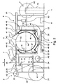
- FIG. 2 shows in detail the disposition of each of these organs.
- the feeding station (2) comprises a frame (20) on which is mounted a reel (21) for a product in the form of a continuous strip supported by a spacer (22); the storage coil is driven by an engine (not shown) about a horizontal axis A1 perpendicular to the direction L.
- the interlayer (22) is unwound around a first roll of separation (23) rotatably mounted on the frame (20) about an axis A2 parallel to A1, and is wound around a recovery reel (24) also mounted on the chassis (20), rotating about an axis A3 parallel to A1 and A2.
- a band conveyor (25) mounted on the frame (20) serves to receive and guide the strip of product at the exit of the separation roller.
- the cutting tool (3) in the proposed embodiment, is mounted on a mobile carriage (30) having guide wheels (31) and motorized wheels (32), and moves in the transverse direction (T) on a rail (33) and a path of bearing (34) mounted on the frame (20).
- a measurement system (not shown) makes it possible to accurately determine the unwrapped tape length and order the cut in order to get a stretch of product of the desired length.
- the cutting tool is adapted to the nature of the product to cut.
- the transfer and storage device (4) comprises a storage cylinder (40) rotatably mounted on a frame (49) about a perpendicular horizontal axis A4 to the feeding direction (L).
- This cylinder is surrounded by a flexible band (45) forming a closed loop and circulating on a set of guides (46) mounted on the frame (49) along axes parallel to the axis A4.
- This set of guides can example be formed by a set of pulleys.
- the part of the cylinder (40) surrounded by the flexible strip located on the half lower part of the latter, represents an angular aperture preferably between 180 ° and 240 °.
- the complementary cylinder part located in the upper part of the cylinder (40) is left free. In any case, we will manage to determine the diameter of the cylinder (40) and the length of the circumference portion thereof contact with the flexible band so that this length is greater than the length of the sections of product to be handled.
- the cylinder (40) is motorized by a motor (not shown) and, when rotation around its axis of revolution A4, it can cause friction band flexible (45), in the manner of a driving pulley.
- the cylinder and the flexible band are able to drive together by friction a stretch of product strip caught between them, to wind this section around the cylinder.
- a tensioning system (47, 48) ensures a constant tension of the web flexible and allows to maintain without deforming product sections thicknesses and of variable masses.
- This system can be constituted by pneumatic cylinders acting on the axes of the pulleys selected for this purpose, and slidably mounted in lights or even by calibrated masses.
- the frame (49) of this device is mounted in rotation on a support (50) around a second axis (A5) vertical and perpendicular to the axis of revolution (A4) of the storage cylinder and passing through the equator of the cylinder of storage.
- a second axis (A5) vertical and perpendicular to the axis of revolution (A4) of the storage cylinder and passing through the equator of the cylinder of storage.
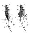
- Figure 5 is detailed the situation of a section of product before turning (P) and after turning (P ') by 180 ° about an axis (A0), perpendicular to the plane of the product and passing through its center.
- the support (50) is mounted on the frame (51) of a movable carriage (5) moving in the direction perpendicular to the feeding direction (L).
- This cart includes guide wheels (52) and motorized wheels (53) that move respectively on rails (54) and on a race (55).
- the cart allows to position the transfer and storage system to the right of the cutting tool (3) and the storage coil (2) from which it is desired to extract a product section. After loading this section around the storage cylinder, the transverse displacement of the carriage at a predetermined position to the right of the receiving station (6) or the drum (7) allows the product section to be unloaded on the receiving station or on the drum by prepositioning it before its final removal on the drum (7).
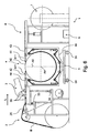
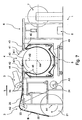
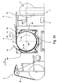
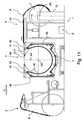
- FIG. 3 and 4 illustrate a referral according to the invention.
- the arm (41) is pivotally mounted about an axis (A7) secured to the frame (49) and parallel to the axis of rotation of the cylinder (A4). It is equipped with an endless conveyor belt (411) driven by a motor (not shown) and flowing in a direction perpendicular to the pivot axis (A7). In position as shown in FIG. 3, the end of the arm (412) is brought to near the surface of the cylinder (40).
- proximity we mean the most low possible to avoid contact between the end of the arm (412) and the surface of the storage cylinder, while ensuring the transfer of a section of product from the surface of the storage cylinder to the conveyor belt (411) of the storage arm (41) without degradation of the product.
- the free end (412) of the arm In the open position, as illustrated in FIG. the free end (412) of the arm is at a distance from the surface of the cylinder (40). This distance must be sufficient to allow a section of product deposited on the surface of the cylinder to circulate freely.
- the storage device serving as a support for the present description comprises two arms (41 and 42), arranged opposite one another, on either side of the storage cylinder, each equipped with a conveyor belt (411 and 421). This provision turns out especially practical when considering the return of product sections, switches (41 and 42) being positioned alternatively at the input and at the output of the storage and transfer device.
- Conveyor belts (43, 44) secured to the frame (49) provide the transfer the product section at the input or at the output of the transfer and storage device (4) and move in the same direction as the conveyor belts with which the arms are equipped pivoting (41 and 42) that they adjoin.
- a receiving device (6) Downstream of the storage and transfer device (4) is a receiving device (6) consisting of a table (61) comprising for example a set of rollers rotatably mounted about transverse axes; these rolls can be at choice, free or motorized.
- the table (61) of the receiving station is mounted on a frame (63), and can be raised by means of a jack (62) to leave free the passage swept by the transfer and storage device (4) when it is rotated about the axis AT 5.
- the drum (7) on which the sections of product are wound successively according to predetermined procedures and locations, is placed at the exit of the post reception.
- the drum (7) is rotatably mounted on a frame (70) about an axis horizontal (A6) perpendicular to the feed axis (L).
- the installation variants are numerous and can lead to the development of the transfer and storage device (4).
- a first variant (not shown) is to fix the cutting tool (3) on the frame (49) of the transfer and storage device, the carriage (5) ensuring simultaneously the transverse displacement of the frame (49), the cutting tool and the associated conveyor belts (35).
- the product is in the form of a band already cut into sections of a predetermined length.
- the position supply and transfer means located upstream of the transfer station and storage are adapted to bring these pre-cut sections directly to the process of transfer and storage where is turned over, if necessary, then to operate the unloading of the product section at a determined transverse position on the receiving station or on the drum.
- power stations can be distributed on a carousel that is operated to come to place the right of (or) device (s) for transfer and storage the (or) station (s) supply (s) selected.
Claims (12)
- Speicher- und Übertragungsvorrichtung (4) für Bandabschnitte von Kautschukprodukten (P), die zur Herstellung eines Luftreifenmantels bestimmt sind, mit einem Speicherzylinder (40), der um eine waagrechte Drehachse (A4) drehbar auf einen Rahmen (49) montiert ist, dadurch gekennzeichnet, dass der Rahmen (49) um eine senkrechte Achse (A5) drehbar auf einen Träger (50) montiert ist, die lotrecht zur Drehachse (A4) des Speicherzylinders (40) liegt.
- Speicher- und Übertragungsvorrichtung nach Anspruch 1, dadurch gekennzeichnet, dass sie ein elastisches Band (45) aufweist, das eine geschlossene Schleife bildet, die um einen Teil des Zylinders (40) und über einen Satz von Führungen (46) umläuft, wobei der Zylinder (40) und das elastische Band (45) in der Lage sind, den zwischen dem Zylinder (40) und dem elastischen Band (45) gehaltenen Bandabschnitt (P) zu umklammern und durch Reibung mitzunehmen, um den Abschnitt (P) um den Zylinder (40) zu wickeln.
- Speicher- und Übertragungsvorrichtung nach Anspruch 2, dadurch gekennzeichnet, dass der Träger (50) auf einen beweglichen Wagen (5) montiert ist.
- Speicher- und Übertragungsvorrichtung nach Anspruch 3, dadurch gekennzeichnet, dass der bewegliche Wagen (5) von einer Schiene (54) geführt wird, die es ermöglicht, die Speicher-und Übertragungsvorrichtung (4) selektiv vor einen Satz von benachbarten Zufuhrstationen (2) zu bringen und sich dann vor einer Empfangsstation (6) oder einer Trommel (7) zu positionieren.
- Speicher- und Übertragungsvorrichtung nach einem der Ansprüche 3 oder 4, dadurch gekennzeichnet, dass der bewegliche Wagen ein Schneidewerkzeug (3) aufweist, das stromaufwärts vor dem Speicherzylinder (40) angeordnet ist.
- Speicher- und Übertragungsvorrichtung nach einem der Ansprüche 1 bis 5, dadurch gekennzeichnet, dass es mit einem Umstellsystem (41, 42) versehen ist, das den Bandabschnitt (P) führen kann, wenn dieser Abschnitt (P) in den Speicherzylinder (40) eingeführt oder aus dem Zylinder entnommen wird.
- Speicher- und Übertragungsvorrichtung nach Anspruch 6, dadurch gekennzeichnet, dass das Umstellsystem mindestens einen beweglichen Arm (41, 42) aufweist, der auf dem Wagen (49) um eine Achse (A7), die parallel zur Drehachse (A4) des Speicherzylinders (40) liegt, zwischen einer geschlossenen Stellung, in der ein freies Ende des Arms (412) in die Nähe der Oberfläche des Speicherzylinders (40) gebracht wird, und einer offenen Stellung, in der das freie Ende sich in Abstand zur Oberfläche des Speicherzylinders (40) befindet, schwenkbar montiert ist.
- Speicher- und Übertragungsvorrichtung nach Anspruch 7, dadurch gekennzeichnet, dass der Arm mit einem endlosen Transportband (411) versehen ist, das in einer Richtung lotrecht zur Schwenkachse (A7) des Arms umläuft.
- Speicher- und Übertragungsvorrichtung nach Anspruch 6, dadurch gekennzeichnet, dass das Umstellsystem zwei bewegliche Arme (41, 42) aufweist, die zu beiden Seiten des Speicherzylinders (40) einander gegenüber angeordnet sind.
- Speicher- und Übertragungsvorrichtung nach Anspruch 2, dadurch gekennzeichnet, dass das elastische Band (45) durch ein Spannsystem (47, 48) auf einer konstanten Spannung gehalten wird.
- Speicher- und Übertragungsvorrichtung nach Anspruch 2, dadurch gekennzeichnet, dass der Speicherzylinder (40) motorisiert und in der Lage ist, das elastische Band (45) durch Reibung mitzunehmen.
- Verfahren zur Herstellung von Luftreifen, das eine Speicher- und Übertragungsvorrichtung für Bandabschnitte von Kautschukprodukten (P) aufweist, dadurch gekennzeichnet, dass es die folgenden Schritte aufweist:ausgehend von einer Zufuhrstation (2), Aufwickeln eines Abschnitts (P) einer vorbestimmten Länge um einen Speicherzylinder (40), wobei der Zylinder (40) um eine waagrechte Drehachse (A4) drehbar auf einen Rahmen (49) montiert ist, wobei der Rahmen selbst um eine senkrechte Achse (A5) lotrecht zur Drehachse (A4) des Speicherzylinders (40) drehbar auf einen Träger (50) montiert ist,Schwenken des Rahmens (49), auf den der Speicherzylinder (40) montiert ist, um 180° um die Drehachse (A5) des Rahmens (49),Anordnen der Speichervorrichtung (4) vor einer Empfangsstation (6) oder vor einer Verlegetrommel (7),Übertragen des Abschnitts (P) von der Speichervorrichtung (4) zur Empfangsstation (6) oder zur Verlegetrommel (7), indem er vom Speicherzylinder (40) abgewickelt wird.
Applications Claiming Priority (3)
| Application Number | Priority Date | Filing Date | Title |
|---|---|---|---|
| FR0205241 | 2002-04-25 | ||
| FR0205241A FR2839005A1 (fr) | 2002-04-25 | 2002-04-25 | Procede pour la manutention de produits en bande en vue de leur utilisation pour la fabrication d'une enveloppe de pneumatique |
| PCT/EP2003/003725 WO2003091009A1 (fr) | 2002-04-25 | 2003-04-10 | Dispositif de stockage et de transfert de produits en bande en vue de leur utilisation pour la fabrication d'une enveloppe de pneumatique |
Publications (2)
| Publication Number | Publication Date |
|---|---|
| EP1506086A1 EP1506086A1 (de) | 2005-02-16 |
| EP1506086B1 true EP1506086B1 (de) | 2005-11-09 |
Family
ID=28799950
Family Applications (1)
| Application Number | Title | Priority Date | Filing Date |
|---|---|---|---|
| EP03722439A Expired - Lifetime EP1506086B1 (de) | 2002-04-25 | 2003-04-10 | Speicher- und transfer-vorrichtung von bandförmigen produkten zur verwendung in der reifenherstellung |
Country Status (10)
| Country | Link |
|---|---|
| US (1) | US7351299B2 (de) |
| EP (1) | EP1506086B1 (de) |
| JP (1) | JP4393876B2 (de) |
| CN (1) | CN100421918C (de) |
| AT (1) | ATE309085T1 (de) |
| AU (1) | AU2003229637A1 (de) |
| DE (1) | DE60302242T2 (de) |
| ES (1) | ES2252669T3 (de) |
| FR (1) | FR2839005A1 (de) |
| WO (1) | WO2003091009A1 (de) |
Families Citing this family (9)
| Publication number | Priority date | Publication date | Assignee | Title |
|---|---|---|---|---|
| DE102005046115A1 (de) * | 2005-09-27 | 2007-03-29 | Continental Aktiengesellschaft | Vorrichtung zum Zuführen und Andrücken von Kautschukmaterial zum Aufbau einer Reifenaufbauschicht |
| JP4802863B2 (ja) * | 2006-05-29 | 2011-10-26 | 横浜ゴム株式会社 | 空気入りタイヤの製造方法及び空気入りタイヤの製造装置、並びに空気入りタイヤ |
| NL2001071C2 (nl) * | 2007-12-11 | 2009-06-15 | Vmi Epe Holland | Samenstel van eenheden voor het bouwen van een, ongevulkaniseerde of groene band voor voertuigen. |
| FR2951711B1 (fr) * | 2009-10-28 | 2012-10-05 | Michelin Soc Tech | Tapis de stockage pour une nappe servant a la fabrication de pneumatiques |
| NL2007058C2 (nl) * | 2011-07-06 | 2013-01-08 | Vmi Holland Bv | Samenstel en werkwijze voor het vervaardigen van een groene band. |
| NL2009946C2 (en) | 2012-12-10 | 2014-06-11 | Vmi Holland Bv | Tyre building machine for forming a bead-apex assembly. |
| JP6743476B2 (ja) * | 2016-04-28 | 2020-08-19 | 住友ゴム工業株式会社 | ゴムストリップの貼付装置 |
| JP7355636B2 (ja) * | 2019-12-13 | 2023-10-03 | Toyo Tire株式会社 | グリーンタイヤの成型装置 |
| DE102022205257A1 (de) * | 2022-05-25 | 2023-11-30 | Continental Reifen Deutschland Gmbh | Automatische Einfädelvorrichtung sowie Verfahren zum Einfädeln von Materialbändern |
Family Cites Families (19)
| Publication number | Priority date | Publication date | Assignee | Title |
|---|---|---|---|---|
| US2039532A (en) * | 1933-12-07 | 1936-05-05 | Nat Rubber Machinery Co | Tire building apparatus |
| US3071179A (en) * | 1961-03-30 | 1963-01-01 | Us Rubber Co | Tire building apparatus and method |
| FR1549394A (de) * | 1967-10-09 | 1968-12-13 | ||
| BE754263A (fr) * | 1969-08-06 | 1971-02-01 | Uniroyal Englebert France | Machine pour la fabrication de bandages pneumatiques |
| US3775219A (en) * | 1971-04-05 | 1973-11-27 | Goldsworthy Eng Inc | Composite-tape placement head |
| US3795563A (en) * | 1972-06-19 | 1974-03-05 | Nrm Corp | Tire building machine servicer |
| DE2507726C2 (de) * | 1975-02-22 | 1982-09-30 | Continental Gummi-Werke Ag, 3000 Hannover | Einrichtung zum Verändern der Länge und zum Überführen von Laufstreifen für Fahrzeugluftreifen |
| US4149926A (en) * | 1976-04-26 | 1979-04-17 | Victor E. Buehrle | Method and apparatus for bonding treads to tires |
| IT1096080B (it) * | 1977-05-17 | 1985-08-17 | Dokoupil Jiri | Procedimento e dispositivo per il trattamento a catena di pezzi in lavorazione sostanzialmente bidimensionali |
| DE2740609C2 (de) * | 1977-09-09 | 1982-05-13 | Continental Gummi-Werke Ag, 3000 Hannover | Vorrichtung zum Aufbauen von Luftreifen oder deren Teilen |
| FR2438417A1 (fr) * | 1978-10-13 | 1980-05-09 | Wright Rain Ltd | Machine d'arrosage agricole |
| US4591402A (en) * | 1981-06-22 | 1986-05-27 | Ltv Aerospace And Defense Company | Apparatus and method for manufacturing composite structures |
| GB8312994D0 (en) * | 1983-05-11 | 1983-06-15 | Dunlop Ltd | Tyre building machinery |
| JPS60139439A (ja) * | 1983-12-28 | 1985-07-24 | Yokohama Rubber Co Ltd:The | 柔軟性を有する被供給物の供給装置 |
| GB8411820D0 (en) * | 1984-05-09 | 1984-06-13 | Bates W & A Ltd | Manufacture |
| IT1189672B (it) * | 1986-05-20 | 1988-02-04 | Firestone Int Dev Spa | Metodo per la realizzazione a caldo di pneumatici |
| CN1019079B (zh) * | 1988-05-26 | 1992-11-18 | 尤尼罗亚尔·谷德里奇轮胎公司 | 第二级轮胎装配床及方法 |
| US6039826A (en) | 1997-04-22 | 2000-03-21 | The Yokohama Rubber Co., Ltd. | Method of forming green tire with strip winding |
| JP2000289122A (ja) * | 1999-04-05 | 2000-10-17 | Bridgestone Corp | トレッド成型方法 |
-
2002
- 2002-04-25 FR FR0205241A patent/FR2839005A1/fr active Pending
-
2003
- 2003-04-10 AU AU2003229637A patent/AU2003229637A1/en not_active Abandoned
- 2003-04-10 WO PCT/EP2003/003725 patent/WO2003091009A1/fr active IP Right Grant
- 2003-04-10 AT AT03722439T patent/ATE309085T1/de not_active IP Right Cessation
- 2003-04-10 DE DE60302242T patent/DE60302242T2/de not_active Expired - Lifetime
- 2003-04-10 ES ES03722439T patent/ES2252669T3/es not_active Expired - Lifetime
- 2003-04-10 JP JP2003587609A patent/JP4393876B2/ja not_active Expired - Fee Related
- 2003-04-10 CN CNB03809178XA patent/CN100421918C/zh not_active Expired - Fee Related
- 2003-04-10 EP EP03722439A patent/EP1506086B1/de not_active Expired - Lifetime
-
2004
- 2004-10-25 US US10/971,016 patent/US7351299B2/en not_active Expired - Fee Related
Also Published As
| Publication number | Publication date |
|---|---|
| FR2839005A1 (fr) | 2003-10-31 |
| WO2003091009A1 (fr) | 2003-11-06 |
| DE60302242T2 (de) | 2006-07-20 |
| AU2003229637A1 (en) | 2003-11-10 |
| CN100421918C (zh) | 2008-10-01 |
| JP4393876B2 (ja) | 2010-01-06 |
| US7351299B2 (en) | 2008-04-01 |
| US20050115659A1 (en) | 2005-06-02 |
| DE60302242D1 (de) | 2005-12-15 |
| ATE309085T1 (de) | 2005-11-15 |
| EP1506086A1 (de) | 2005-02-16 |
| ES2252669T3 (es) | 2006-05-16 |
| JP2005523187A (ja) | 2005-08-04 |
| CN1649720A (zh) | 2005-08-03 |
Similar Documents
| Publication | Publication Date | Title |
|---|---|---|
| EP2205369B1 (de) | Vorrichtung zur prüfung eines blechstreifens | |
| FR2553073A1 (fr) | Procede et appareil de transport de bobines enlevees d'un metier | |
| FR2623176A1 (fr) | Appareillage et procede pour traiter la partie d'extremite d'une feuille de papier en rouleau disposee en un emplacement de raccordement | |
| EP1506086B1 (de) | Speicher- und transfer-vorrichtung von bandförmigen produkten zur verwendung in der reifenherstellung | |
| LU83851A1 (fr) | Appareil d'alimentation de couches de renforcement au cours de la fabrication de pneumatiques | |
| FR2612879A1 (fr) | Appareil d'alimentation en un materiau sous forme de film | |
| FR2744598A1 (fr) | Procede et appareil de production d'un aliment cylindrique, et aliment cylindrique | |
| FR2528023A1 (fr) | Procede et dispositif pour la reprise de produits plats se presentant en disposition en ecailles, en particulier pour la reprise de feuilles imprimees | |
| FI87439B (fi) | Anordning foer framstaellning av portabla, roerformiga paket av tryckalster. | |
| EP0944542B1 (de) | Wickelmaschine für ein flaches endloses element zur bildung von bahnwickeln | |
| EP1036026B1 (de) | Wickelmaschine für bahnen, zum wickeln von rollen | |
| EP3239081B1 (de) | Zuführung für verpackvorgänge mit schrumpffolie | |
| EP3870430B1 (de) | Automatische vorrichtung und automatisches verfahren zum querwickeln von streifen von einer gewickelten bahn | |
| EP2957487B1 (de) | Instandsetzungsvorrichtung für eine fahrzeug-laufkette, vorrichtung und verfahren zum wechseln der ketten-laufflächen mithilfe dieser instandsetzungsvorrichtung | |
| EP4076922B1 (de) | Maschine zur automatischen herstellung von luftreifen mit einer "diagonalen" krone | |
| FR2650555A1 (fr) | Procede et machine pour deposer une bande de film de facon helicoidale sur les faces verticales d'une charge palettisee | |
| FR3068341A1 (fr) | Dispositif et procede d'enroulage et de transfert d'une bandelette a partir d'une bobine pleine jusqu'a une bobine vide | |
| FR2482570A1 (fr) | Dispositif pour l'enroulement automatique de produits filiformes, notamment de fil metallique | |
| EP0325498B1 (de) | Vorrichtung zum Laden und Entladen eines Wickelkörpers zur Behandlung von Schüttgut in Schichten | |
| FR2540473A1 (fr) | Machine destinee a traiter et preparer les bandes, et en particulier les bandes a pansement, apres leur fabrication | |
| FR2497781A1 (fr) | Procede pour changer les bobines et les mandrins des machines d'enroulement sans axe | |
| EP1089931A1 (de) | Oberflächenwickel auf wickelmaschine mit a-förmigem rahmen | |
| FR2528007A1 (fr) | Procede et appareil d'emballage d'une bobine de bande metallique | |
| FR2580255A1 (fr) | Procede et dispositif pour deposer une feuille de recouvrement sur le dessus d'un objet emballe deplace longitudinalement | |
| WO1998004487A1 (fr) | Installation permettant de reconditionner sous la forme d'un enroulement une matiere en bande, telle qu'une etoffe |
Legal Events
| Date | Code | Title | Description |
|---|---|---|---|
| PUAI | Public reference made under article 153(3) epc to a published international application that has entered the european phase |
Free format text: ORIGINAL CODE: 0009012 |
|
| 17P | Request for examination filed |
Effective date: 20041125 |
|
| AK | Designated contracting states |
Kind code of ref document: A1 Designated state(s): AT BE BG CH CY CZ DE DK EE ES FI FR GB GR HU IE IT LI LU MC NL PT RO SE SI SK TR |
|
| AX | Request for extension of the european patent |
Extension state: AL LT LV MK |
|
| GRAP | Despatch of communication of intention to grant a patent |
Free format text: ORIGINAL CODE: EPIDOSNIGR1 |
|
| GRAS | Grant fee paid |
Free format text: ORIGINAL CODE: EPIDOSNIGR3 |
|
| GRAA | (expected) grant |
Free format text: ORIGINAL CODE: 0009210 |
|
| AK | Designated contracting states |
Kind code of ref document: B1 Designated state(s): AT BE BG CH CY CZ DE DK EE ES FI FR GB GR HU IE IT LI LU MC NL PT RO SE SI SK TR |
|
| PG25 | Lapsed in a contracting state [announced via postgrant information from national office to epo] |
Ref country code: SK Free format text: LAPSE BECAUSE OF FAILURE TO SUBMIT A TRANSLATION OF THE DESCRIPTION OR TO PAY THE FEE WITHIN THE PRESCRIBED TIME-LIMIT Effective date: 20051109 Ref country code: FI Free format text: LAPSE BECAUSE OF FAILURE TO SUBMIT A TRANSLATION OF THE DESCRIPTION OR TO PAY THE FEE WITHIN THE PRESCRIBED TIME-LIMIT Effective date: 20051109 Ref country code: RO Free format text: LAPSE BECAUSE OF FAILURE TO SUBMIT A TRANSLATION OF THE DESCRIPTION OR TO PAY THE FEE WITHIN THE PRESCRIBED TIME-LIMIT Effective date: 20051109 Ref country code: CZ Free format text: LAPSE BECAUSE OF FAILURE TO SUBMIT A TRANSLATION OF THE DESCRIPTION OR TO PAY THE FEE WITHIN THE PRESCRIBED TIME-LIMIT Effective date: 20051109 Ref country code: IE Free format text: LAPSE BECAUSE OF FAILURE TO SUBMIT A TRANSLATION OF THE DESCRIPTION OR TO PAY THE FEE WITHIN THE PRESCRIBED TIME-LIMIT Effective date: 20051109 Ref country code: AT Free format text: LAPSE BECAUSE OF FAILURE TO SUBMIT A TRANSLATION OF THE DESCRIPTION OR TO PAY THE FEE WITHIN THE PRESCRIBED TIME-LIMIT Effective date: 20051109 Ref country code: NL Free format text: LAPSE BECAUSE OF FAILURE TO SUBMIT A TRANSLATION OF THE DESCRIPTION OR TO PAY THE FEE WITHIN THE PRESCRIBED TIME-LIMIT Effective date: 20051109 Ref country code: SI Free format text: LAPSE BECAUSE OF FAILURE TO SUBMIT A TRANSLATION OF THE DESCRIPTION OR TO PAY THE FEE WITHIN THE PRESCRIBED TIME-LIMIT Effective date: 20051109 |
|
| REG | Reference to a national code |
Ref country code: GB Ref legal event code: FG4D Free format text: NOT ENGLISH |
|
| REG | Reference to a national code |
Ref country code: CH Ref legal event code: EP |
|
| REG | Reference to a national code |
Ref country code: IE Ref legal event code: FG4D Free format text: LANGUAGE OF EP DOCUMENT: FRENCH |
|
| REF | Corresponds to: |
Ref document number: 60302242 Country of ref document: DE Date of ref document: 20051215 Kind code of ref document: P |
|
| PG25 | Lapsed in a contracting state [announced via postgrant information from national office to epo] |
Ref country code: BG Free format text: LAPSE BECAUSE OF FAILURE TO SUBMIT A TRANSLATION OF THE DESCRIPTION OR TO PAY THE FEE WITHIN THE PRESCRIBED TIME-LIMIT Effective date: 20060209 Ref country code: SE Free format text: LAPSE BECAUSE OF FAILURE TO SUBMIT A TRANSLATION OF THE DESCRIPTION OR TO PAY THE FEE WITHIN THE PRESCRIBED TIME-LIMIT Effective date: 20060209 Ref country code: GR Free format text: LAPSE BECAUSE OF FAILURE TO SUBMIT A TRANSLATION OF THE DESCRIPTION OR TO PAY THE FEE WITHIN THE PRESCRIBED TIME-LIMIT Effective date: 20060209 Ref country code: DK Free format text: LAPSE BECAUSE OF FAILURE TO SUBMIT A TRANSLATION OF THE DESCRIPTION OR TO PAY THE FEE WITHIN THE PRESCRIBED TIME-LIMIT Effective date: 20060209 |
|
| GBT | Gb: translation of ep patent filed (gb section 77(6)(a)/1977) |
Effective date: 20060131 |
|
| PG25 | Lapsed in a contracting state [announced via postgrant information from national office to epo] |
Ref country code: PT Free format text: LAPSE BECAUSE OF FAILURE TO SUBMIT A TRANSLATION OF THE DESCRIPTION OR TO PAY THE FEE WITHIN THE PRESCRIBED TIME-LIMIT Effective date: 20060410 |
|
| PG25 | Lapsed in a contracting state [announced via postgrant information from national office to epo] |
Ref country code: MC Free format text: LAPSE BECAUSE OF NON-PAYMENT OF DUE FEES Effective date: 20060430 Ref country code: BE Free format text: LAPSE BECAUSE OF NON-PAYMENT OF DUE FEES Effective date: 20060430 |
|
| NLV1 | Nl: lapsed or annulled due to failure to fulfill the requirements of art. 29p and 29m of the patents act | ||
| PG25 | Lapsed in a contracting state [announced via postgrant information from national office to epo] |
Ref country code: HU Free format text: LAPSE BECAUSE OF FAILURE TO SUBMIT A TRANSLATION OF THE DESCRIPTION OR TO PAY THE FEE WITHIN THE PRESCRIBED TIME-LIMIT Effective date: 20060510 |
|
| REG | Reference to a national code |
Ref country code: ES Ref legal event code: FG2A Ref document number: 2252669 Country of ref document: ES Kind code of ref document: T3 |
|
| REG | Reference to a national code |
Ref country code: IE Ref legal event code: FD4D |
|
| PLBE | No opposition filed within time limit |
Free format text: ORIGINAL CODE: 0009261 |
|
| STAA | Information on the status of an ep patent application or granted ep patent |
Free format text: STATUS: NO OPPOSITION FILED WITHIN TIME LIMIT |
|
| 26N | No opposition filed |
Effective date: 20060810 |
|
| REG | Reference to a national code |
Ref country code: CH Ref legal event code: PL |
|
| BERE | Be: lapsed |
Owner name: SOC. DE TECHNOLOGIE MICHELIN Effective date: 20060430 Owner name: MICHELIN RECHERCHE ET TECHNIQUE S.A. Effective date: 20060430 |
|
| PG25 | Lapsed in a contracting state [announced via postgrant information from national office to epo] |
Ref country code: CH Free format text: LAPSE BECAUSE OF NON-PAYMENT OF DUE FEES Effective date: 20070430 Ref country code: LI Free format text: LAPSE BECAUSE OF NON-PAYMENT OF DUE FEES Effective date: 20070430 |
|
| PG25 | Lapsed in a contracting state [announced via postgrant information from national office to epo] |
Ref country code: EE Free format text: LAPSE BECAUSE OF FAILURE TO SUBMIT A TRANSLATION OF THE DESCRIPTION OR TO PAY THE FEE WITHIN THE PRESCRIBED TIME-LIMIT Effective date: 20051109 |
|
| PG25 | Lapsed in a contracting state [announced via postgrant information from national office to epo] |
Ref country code: LU Free format text: LAPSE BECAUSE OF NON-PAYMENT OF DUE FEES Effective date: 20060410 Ref country code: TR Free format text: LAPSE BECAUSE OF FAILURE TO SUBMIT A TRANSLATION OF THE DESCRIPTION OR TO PAY THE FEE WITHIN THE PRESCRIBED TIME-LIMIT Effective date: 20051109 |
|
| PG25 | Lapsed in a contracting state [announced via postgrant information from national office to epo] |
Ref country code: CY Free format text: LAPSE BECAUSE OF FAILURE TO SUBMIT A TRANSLATION OF THE DESCRIPTION OR TO PAY THE FEE WITHIN THE PRESCRIBED TIME-LIMIT Effective date: 20051109 |
|
| PGFP | Annual fee paid to national office [announced via postgrant information from national office to epo] |
Ref country code: GB Payment date: 20090421 Year of fee payment: 7 |
|
| GBPC | Gb: european patent ceased through non-payment of renewal fee |
Effective date: 20100410 |
|
| PG25 | Lapsed in a contracting state [announced via postgrant information from national office to epo] |
Ref country code: GB Free format text: LAPSE BECAUSE OF NON-PAYMENT OF DUE FEES Effective date: 20100410 |
|
| REG | Reference to a national code |
Ref country code: FR Ref legal event code: PLFP Year of fee payment: 14 |
|
| REG | Reference to a national code |
Ref country code: FR Ref legal event code: PLFP Year of fee payment: 15 |
|
| REG | Reference to a national code |
Ref country code: FR Ref legal event code: PLFP Year of fee payment: 16 |
|
| PGFP | Annual fee paid to national office [announced via postgrant information from national office to epo] |
Ref country code: ES Payment date: 20180525 Year of fee payment: 16 Ref country code: DE Payment date: 20180420 Year of fee payment: 16 |
|
| PGFP | Annual fee paid to national office [announced via postgrant information from national office to epo] |
Ref country code: IT Payment date: 20180423 Year of fee payment: 16 Ref country code: FR Payment date: 20180420 Year of fee payment: 16 |
|
| REG | Reference to a national code |
Ref country code: DE Ref legal event code: R119 Ref document number: 60302242 Country of ref document: DE |
|
| PG25 | Lapsed in a contracting state [announced via postgrant information from national office to epo] |
Ref country code: DE Free format text: LAPSE BECAUSE OF NON-PAYMENT OF DUE FEES Effective date: 20191101 |
|
| PG25 | Lapsed in a contracting state [announced via postgrant information from national office to epo] |
Ref country code: FR Free format text: LAPSE BECAUSE OF NON-PAYMENT OF DUE FEES Effective date: 20190430 |
|
| PG25 | Lapsed in a contracting state [announced via postgrant information from national office to epo] |
Ref country code: IT Free format text: LAPSE BECAUSE OF NON-PAYMENT OF DUE FEES Effective date: 20190410 |
|
| REG | Reference to a national code |
Ref country code: ES Ref legal event code: FD2A Effective date: 20200831 |
|
| PG25 | Lapsed in a contracting state [announced via postgrant information from national office to epo] |
Ref country code: ES Free format text: LAPSE BECAUSE OF NON-PAYMENT OF DUE FEES Effective date: 20190411 |