EP4076922B1 - Maschine zur automatischen herstellung von luftreifen mit einer "diagonalen" krone - Google Patents
Maschine zur automatischen herstellung von luftreifen mit einer "diagonalen" krone Download PDFInfo
- Publication number
- EP4076922B1 EP4076922B1 EP20824608.2A EP20824608A EP4076922B1 EP 4076922 B1 EP4076922 B1 EP 4076922B1 EP 20824608 A EP20824608 A EP 20824608A EP 4076922 B1 EP4076922 B1 EP 4076922B1
- Authority
- EP
- European Patent Office
- Prior art keywords
- carcass
- zone
- ply
- entity
- drum
- Prior art date
- Legal status (The legal status is an assumption and is not a legal conclusion. Google has not performed a legal analysis and makes no representation as to the accuracy of the status listed.)
- Active
Links
- 238000004519 manufacturing process Methods 0.000 title claims description 103
- 238000012546 transfer Methods 0.000 claims description 88
- 230000003014 reinforcing effect Effects 0.000 claims description 33
- 238000007493 shaping process Methods 0.000 claims description 27
- 238000004804 winding Methods 0.000 claims description 16
- 238000002360 preparation method Methods 0.000 claims description 14
- 238000009826 distribution Methods 0.000 claims description 13
- 239000013536 elastomeric material Substances 0.000 claims description 6
- 230000002787 reinforcement Effects 0.000 description 101
- 230000010287 polarization Effects 0.000 description 75
- 241001417494 Sciaenidae Species 0.000 description 24
- 235000009508 confectionery Nutrition 0.000 description 17
- 238000009434 installation Methods 0.000 description 13
- 239000000470 constituent Substances 0.000 description 7
- 238000000034 method Methods 0.000 description 7
- 230000004048 modification Effects 0.000 description 7
- 238000012986 modification Methods 0.000 description 7
- 230000008901 benefit Effects 0.000 description 6
- 230000008569 process Effects 0.000 description 6
- 230000032258 transport Effects 0.000 description 6
- 239000011324 bead Substances 0.000 description 5
- 238000005520 cutting process Methods 0.000 description 5
- 238000005096 rolling process Methods 0.000 description 5
- 238000013519 translation Methods 0.000 description 5
- 230000000694 effects Effects 0.000 description 4
- 230000005415 magnetization Effects 0.000 description 4
- 239000000463 material Substances 0.000 description 4
- 238000011144 upstream manufacturing Methods 0.000 description 4
- 238000010411 cooking Methods 0.000 description 3
- 239000002184 metal Substances 0.000 description 3
- 238000005070 sampling Methods 0.000 description 3
- 241001080024 Telles Species 0.000 description 2
- 240000008042 Zea mays Species 0.000 description 2
- 230000009471 action Effects 0.000 description 2
- 238000010276 construction Methods 0.000 description 2
- 229940082150 encore Drugs 0.000 description 2
- 230000003993 interaction Effects 0.000 description 2
- 230000000670 limiting effect Effects 0.000 description 2
- 238000012423 maintenance Methods 0.000 description 2
- 239000003607 modifier Substances 0.000 description 2
- 230000036961 partial effect Effects 0.000 description 2
- 238000012545 processing Methods 0.000 description 2
- 230000002829 reductive effect Effects 0.000 description 2
- 241000135309 Processus Species 0.000 description 1
- 238000000429 assembly Methods 0.000 description 1
- 238000007664 blowing Methods 0.000 description 1
- 238000006073 displacement reaction Methods 0.000 description 1
- 238000005265 energy consumption Methods 0.000 description 1
- 239000000446 fuel Substances 0.000 description 1
- 230000001939 inductive effect Effects 0.000 description 1
- 230000010354 integration Effects 0.000 description 1
- 238000005304 joining Methods 0.000 description 1
- 238000007726 management method Methods 0.000 description 1
- 230000007246 mechanism Effects 0.000 description 1
- 239000012528 membrane Substances 0.000 description 1
- 239000007769 metal material Substances 0.000 description 1
- 238000012856 packing Methods 0.000 description 1
- 230000001012 protector Effects 0.000 description 1
- 238000011084 recovery Methods 0.000 description 1
- 230000000284 resting effect Effects 0.000 description 1
- 230000000717 retained effect Effects 0.000 description 1
- 238000000926 separation method Methods 0.000 description 1
- 230000001360 synchronised effect Effects 0.000 description 1
- 239000004753 textile Substances 0.000 description 1
- 230000007704 transition Effects 0.000 description 1
- 239000004636 vulcanized rubber Substances 0.000 description 1
- 239000002699 waste material Substances 0.000 description 1
Images


Classifications
-
- B—PERFORMING OPERATIONS; TRANSPORTING
- B29—WORKING OF PLASTICS; WORKING OF SUBSTANCES IN A PLASTIC STATE IN GENERAL
- B29D—PRODUCING PARTICULAR ARTICLES FROM PLASTICS OR FROM SUBSTANCES IN A PLASTIC STATE
- B29D30/00—Producing pneumatic or solid tyres or parts thereof
- B29D30/06—Pneumatic tyres or parts thereof (e.g. produced by casting, moulding, compression moulding, injection moulding, centrifugal casting)
- B29D30/08—Building tyres
- B29D30/20—Building tyres by the flat-tyre method, i.e. building on cylindrical drums
- B29D30/30—Applying the layers; Guiding or stretching the layers during application
-
- B—PERFORMING OPERATIONS; TRANSPORTING
- B29—WORKING OF PLASTICS; WORKING OF SUBSTANCES IN A PLASTIC STATE IN GENERAL
- B29D—PRODUCING PARTICULAR ARTICLES FROM PLASTICS OR FROM SUBSTANCES IN A PLASTIC STATE
- B29D30/00—Producing pneumatic or solid tyres or parts thereof
- B29D30/06—Pneumatic tyres or parts thereof (e.g. produced by casting, moulding, compression moulding, injection moulding, centrifugal casting)
- B29D30/08—Building tyres
- B29D30/20—Building tyres by the flat-tyre method, i.e. building on cylindrical drums
- B29D30/24—Drums
- B29D30/26—Accessories or details, e.g. membranes, transfer rings
- B29D30/2607—Devices for transferring annular tyre components during the building-up stage, e.g. from the first stage to the second stage building drum
-
- B—PERFORMING OPERATIONS; TRANSPORTING
- B29—WORKING OF PLASTICS; WORKING OF SUBSTANCES IN A PLASTIC STATE IN GENERAL
- B29D—PRODUCING PARTICULAR ARTICLES FROM PLASTICS OR FROM SUBSTANCES IN A PLASTIC STATE
- B29D30/00—Producing pneumatic or solid tyres or parts thereof
- B29D30/0061—Accessories, details or auxiliary operations not otherwise provided for
-
- B—PERFORMING OPERATIONS; TRANSPORTING
- B29—WORKING OF PLASTICS; WORKING OF SUBSTANCES IN A PLASTIC STATE IN GENERAL
- B29D—PRODUCING PARTICULAR ARTICLES FROM PLASTICS OR FROM SUBSTANCES IN A PLASTIC STATE
- B29D30/00—Producing pneumatic or solid tyres or parts thereof
- B29D30/06—Pneumatic tyres or parts thereof (e.g. produced by casting, moulding, compression moulding, injection moulding, centrifugal casting)
- B29D30/08—Building tyres
- B29D30/20—Building tyres by the flat-tyre method, i.e. building on cylindrical drums
- B29D30/22—Breaker plies being applied in the unexpanded state
-
- B—PERFORMING OPERATIONS; TRANSPORTING
- B29—WORKING OF PLASTICS; WORKING OF SUBSTANCES IN A PLASTIC STATE IN GENERAL
- B29D—PRODUCING PARTICULAR ARTICLES FROM PLASTICS OR FROM SUBSTANCES IN A PLASTIC STATE
- B29D30/00—Producing pneumatic or solid tyres or parts thereof
- B29D30/06—Pneumatic tyres or parts thereof (e.g. produced by casting, moulding, compression moulding, injection moulding, centrifugal casting)
- B29D30/08—Building tyres
- B29D30/20—Building tyres by the flat-tyre method, i.e. building on cylindrical drums
- B29D30/30—Applying the layers; Guiding or stretching the layers during application
- B29D2030/3064—Details, accessories and auxiliary operations not otherwise provided for
Definitions
- the present invention relates to the field of manufacturing pneumatic tires.
- An automatic tire manufacturing machine is described, for example, in the document WO 2018/096511 A1 .
- first annular block which comprises at least one carcass ply containing reinforcing wires which extend along radial planes relative to the central axis of the tire, and which is shaped, preferably by inflation, so as to have a toroidal shape
- second annular block which comprises a tread, as well as layers reinforcement, called “top layers”, which each have reinforcing wires arranged parallel to each other and obliquely relative to the circumferential direction of the bandage, at an angle called “ply angle”.
- Such a tire architecture called “radial carcass” has numerous advantages, particularly in terms of road holding.
- the conformation parameters as well as the initial orientation of the reinforcing wires of the carcass ply and the second ply, here preferably a top ply, it is possible to control the rotation of the direction of the reinforcing wires respective of each ply, and thus to obtain, after conformation, the final angular orientation desired for the different reinforcing wires.
- Another advantage is that the interaction between reinforcing threads belonging to two distinct layers, interaction which is due to the crossing of said reinforcing threads created by the superposition and joining of the layers, occurs, and causes a modification of orientation of the direction of said reinforcing wires, mainly or even exclusively in the covering zone, and little, if any, outside of said covering zone.
- the objects assigned to the invention therefore aim to remedy the aforementioned drawbacks and propose a new bandage manufacturing machine which allows efficient production of bandages having a polarized top architecture.
- the machine according to the invention makes it possible to carry out, in a limited time and in a reduced space, all of the operations making it possible to constitute a bandage having a polarized vertex architecture.
- the tire from the machine is preferably a raw rubber-based tire, ready to be sent to cooking to be vulcanized.
- the proximity of the manufacturing, finishing and assembly zones advantageously limits the footprint of the machine according to the invention as well as the amplitude of the transfer movements of the different constituent blocks of the tire, which makes it possible to reduce the cycle time and energy consumption of said machine.
- the automation of the manufacturing process, and the simultaneous realization of the manufacturing steps of different constituent elements of the tire, in this case the crown block on the one hand and the carcass block on the other hand, makes it possible to optimize said cycle time.
- the modular architecture of the proposed machine makes it possible in particular to exploit certain mechanical sub-assemblies already known and proven, particularly in terms of producing the carcass block and/or producing the top block, which contributes to good reliability. of the machine, and simplifies the integration of said machine within workshops and its handling by operators.
- the machine according to the invention can advantageously present great versatility, insofar as it is possible to configure said machine in such a way that it can produce both tires having a radial carcass architecture and tires having an architecture with polarized top.
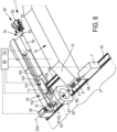
- the invention relates to a machine 1, as illustrated in particular on the figures 1 , 3 And 6 , which is intended for the automatic manufacture of a tire, and more preferably for the automatic manufacture of a pneumatic tire.
- Said machine 1 comprises a first zone 2, called “constructing zone” 2, arranged to produce a first annular block 3 constituting the tire, called “carcass block” 3, which comprises at least one carcass ply 4 provided with a first set of wire reinforcement elements 5, called “carcass reinforcements” 5, as is particularly visible on the figures 2 , 4 And 7 .
- wire is meant an element extending longitudinally along a main line and which has a section perpendicular to said main line whose largest dimension, called “transverse dimension” G, is relatively small compared to the dimension called " longitudinal dimension » L considered along said main line.
- transverse dimension G
- L longitudinal dimension » L considered along said main line.
- relatively low we mean that the L/G ratio is greater than or equal to 100, preferably greater than or equal to 1000.
- This definition covers both wire elements of circular section and wire elements of non-circular section, for example example of polygonal or oblong section.
- each wire element has a circular section.
- the carcass ply 4 is preferably formed, in a manner known per se, from a ply of elastomeric material, preferably based on raw rubber, that is to say unvulcanized rubber, in which the carcass reinforcements 5.
- said carcass reinforcements 5 extend in length parallel to each other and each continuously from a side edge of said carcass ply 4 to the opposite side edge.
- the carcass reinforcements 5 have a stiffness, that is to say a tensile strength modulus, which is strictly greater than the tensile modulus of the raw rubber constituting the ply, and more generally greater than the tensile modulus of the vulcanized rubber. , so as to give the carcass ply 4 a quasi-inextensible character in the direction of the length of said carcass reinforcements 5.
- the carcass reinforcements 5 may be formed by wires or cables of any suitable material, preferably of textile material or of metallic material.
- the manufacturing zone 2 comprises a manufacturing drum 6, which has a central drum axis X6 and which is mounted to rotate around said central drum axis X6.
- Said drum 6 is thus carried by, and mounted in rotation on, a drum frame 7, preferably cantilevered relative to said drum frame 7.
- Said drum frame 7 preferably comprises a drive motor, preferably electric, making it possible to drive the drum 6 in rotation around its central axis X6.
- the manufactured drum 6 has, at least initially during the installation of the carcass ply 4, a receiving surface, preferably cylindrical with a circular base, which forms a surface of revolution around the central axis X6 of the drum , and which is intended to receive the components of the carcass block 3.
- a receiving surface preferably cylindrical with a circular base, which forms a surface of revolution around the central axis X6 of the drum , and which is intended to receive the components of the carcass block 3.
- the manufacturing zone 2 also includes a first feed system 10 which is arranged to place a carcass sheet 4 on the manufacturing drum 6 by winding on said manufacturing drum 6, around the central axis of the drum X6, and this so that the carcass reinforcements 5 have, relative to a circumferential direction C6 of the drum, a first angular orientation A5_1.
- the first feed system 10 may in particular comprise a conveyor belt 13, which extends transversely to the central axis of the drum X6 and which opens opposite said drum 6.
- circumferential direction here more precisely by “circumferential direction C6 of the drum”, we mean the direction which, at the point considered, is substantially perpendicular to both the axial reference direction considered, that is to say here perpendicular to the direction of the central axis of the drum
- the circumferential direction C6 of the drum corresponds here to the fictitious curve, preferably a circle, with regard to the preferably circular section of the drum 6, such that said fictitious curve is defined by the intersection of the cylindrical receiving surface of the drum 6, which receives the constituents of the carcass block 3, with a gauge plane normal to the central axis X6 of the drum.
- the circumferential direction C6 thus corresponds, at any point considered on the circumference of the drum, to the ortho-radial vector which defines the tangent to said circumference of the drum at the point considered, in said gauge plane.
- said gauge plane corresponds to the equatorial plane P_EQ of the tire, and more particularly to the equatorial plane of the carcass block 3, centered axially with respect to the carcass block 2, and which thus axially subdivides said carcass block 3 into two substantially symmetrical hemispheres, of the same axial height, such that the circumferential direction C6 substantially coincides with the equatorial line of the carcass block 3.
- the carcass reinforcements 5 initially extend, during the “flat” laying of the carcass ply 4 on the drum 6, before shaping, along radial planes which contain the central axis X6 of the drum.
- the carcass reinforcements 5 thus extend preferably parallel to the central axis X6, as is particularly visible on the figures 13 and 14 .
- the first angular orientation A5_1 corresponds in this case to a perpendicular orientation, the carcass reinforcements 5 in fact forming an angle of 90 degrees (or substantially 90 degrees, for example between 85 and 95 degrees) relative to the circumferential direction C6 .
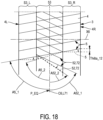
- first angular orientation A5_1 according to which the carcass reinforcements 5 would initially be arranged obliquely with respect to the circumferential direction C6, as is the case at purely illustrative title on the Figure 18 , for example by forming, before conformation, an angle of between 27 and 150 degrees, preferably between 56 degrees and 123 degrees with respect to said circumferential direction C6.
- the carcass reinforcements 5 extend parallel to each other, and are each axially continuous, from a first edge 4L forming, with reference to the axial direction of the drum X6, an axial end from the carcass ply 4 to a second edge 4R forming the opposite axial end of said carcass ply 4.
- each material constituting the reinforcing wire element and therefore more generally said reinforcing wire element, here in particular each carcass reinforcement 5, extends in an uninterrupted manner, preferably by a in one piece, over the entire length of said reinforcing wire element.
- the carcass reinforcements 5 will be able to connect two annular rods 11, 12 to each other.
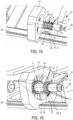
- Said annular rods 11, 12, preferably made from metal wire braids, will be integrated into the carcass block 3, concentrically with the central axis of the drum X6, as is visible on the Figure 15 , to subsequently allow the tire to be attached to a rim.
- each of said rods 11, 12 will be attached to the carcass block 3 in the form of a sub-assembly called “heel block” which comprises said rod 11, 12 as well as a rubber ring, not represented here, which is called “bead packing”, which has a substantially triangular transverse section, and whose radially internal base is arranged to press against or even surround the section of the bead 11, 12 in the bead zone through which the tire comes resting on the rim.
- the manufacturing zone 2, and more preferably the first feed system 10, will of course be arranged to place other possible components of the carcass block 3 on the drum.
- the first supply system 10 will preferably make it possible to wind on the drum 6, prior to the installation of the carcass ply 4, a film called “inner rubber”, which is intended to ensure watertightness. air from the bandage.
- the first feed system 10 could be designed to place and wind on the drum 6, around the central axis X6, a “complex” (not shown), that is to say a subassembly which will have been, to reduce the cycle time of the machine 1, pre-assembled before being brought to the drum 6, and which will include for example the inner rubber, as well as two strips of rubber covering the lateral portions of said inner rubber and intended to form the outer sides of the tire, and, possibly, rubber cushions called “bead protectors”, intended to reinforce the beads of the tire at the level of the beadings 11, 12.
- a “complex” not shown
- a subassembly which will have been, to reduce the cycle time of the machine 1, pre-assembled before being brought to the drum 6, and which will include for example the inner rubber, as well as two strips of rubber covering the lateral portions of said inner rubber and intended to form the outer sides of the tire, and, possibly, rubber cushions called “bead protectors”, intended to reinforce the beads of the tire at the level of the bea
- the carcass layer 4 will then be placed on the drum 6, over said complex.
- the machine 1 also includes a second zone 20, called “finishing zone” 20, arranged to produce a second annular block 21 constituting the tire, called “top block” 21, which comprises at least one tread 22.
- Said finishing zone 20 comprises for this purpose a ferrule 23 mounted to rotate around a central axis around the central axis of ferrule X23, as illustrated on the Figure 12 .
- the ferrule 23 is carried, preferably cantilevered, by a ferrule frame 25, capable of driving said ferrule 23 in rotation around its central axis X23.
- Said shell frame 25 is provided for this purpose with a drive motor, preferably an electric motor.
- the ferrule 23 will preferably have a receiving surface having a shape of revolution around the central axis of the ferrule to receive the components of the top block 21.
- the central axis of the shell X23 will be parallel to the central axis of the drum X6.
- the common direction, parallel to these two central axes X6, X23 will define, by convention, a global axial direction of machine 1.
- finishing zone 20 will include, if necessary, the equipment 26, 27 necessary to place the various other constituent components of the top block 21 by winding on the ferrule 23.
- the finishing zone 20 may include truncation equipment, designed to place on the ferrule 23, before the installation of the tread 22 and therefore radially under said tread 22, a strapping ring, said hoop being obtained by winding a continuous reinforced strip in a helix around the central axis of ferrule X23, in several consecutive contiguous turns.
- the reinforced strip used to make the hoop will contain continuous hoop reinforcements, which extend parallel to each other and parallel to the longitudinal direction of said reinforced strip so that, ultimately, said hoop reinforcements are will be found in the top block 21, and more generally in the bandage, oriented relative to the circumferential direction C6 at an angle which corresponds to the helix angle of the turns of said hoop, and which is relatively weak, for example less than or equal to 5 degrees, so that said reinforcements extend substantially in the circumferential direction.
- the installation of the hoop within the finishing zone 20 will be carried out by choosing, during transcanning, a helix angle which will preferably be less than or equal to 10 degrees, preferably less than or equal to 7 degrees , and more preferably less than or equal to 5 degrees.
- the equipment 26, 27 of the finishing zone may include several delivery systems if necessary, as is visible in particular on the figures 1 , 2 , 3 , 6 Or 7 , each delivery system being capable of conveying at least one of the constituents of the top block 21 to the ferrule 23.
- the equipment in particular the feed systems, 24, 26, 27, can be staged axially and/or vertically at the level of the finishing zone 20, for good compactness of the together.
- the ferrule frame 25 can then be provided with a movement mechanism allowing it to move horizontally (along the ferrule axis X23) and/or vertically so that said ferrule frame 25 can come to present the ferrule 23 successively opposite the different equipment and supply systems 24, 26, 27, in order to collect the different constituents of the top block 21 in the desired order.
- the machine 1 further comprises a shaping system 30, arranged to carry out a shaping operation which causes a radial expansion of the carcass block 3 present on the manufacturing drum 6, in order to obtain a so-called “shaped” carcass block 3, of toroidal shape, as visible on the Figure 16 .
- Such a conformation system 30 essentially makes it possible to bring the first rod 11 and the second rod 12 axially closer to each other, while pushing back radially, according to a centrifugal radial expansion movement relative to the central axis the final shape of the bandage. In doing so, a circumferential expansion of the carcass block 3 is also caused, along the circumferential direction C6.
- said conformation system 30 will make it possible to pass the carcass block 3 from a retracted configuration, preferably cylindrical with a circular base, which corresponds to the "flat" configuration according to which the inner rubber and the carcass ply 4 are initially placed by winding on the drum 6, in an deployed configuration, in which said carcass block 3 has a toroidal shape, convexed radially outwards, which preferably corresponds substantially to the shape that said carcass block 3 will adopt within the tire finished.
- the conformation system 30 operates by inflation, so as to produce the expansion of the carcass block 3 by blowing, inside the sealed cavity which is delimited by the wall formed by the constituent layers of the carcass block 3, and more particularly by the wall formed by the interior rubber, a gas, for example air, under a predetermined pressure, called “conformation pressure”, greater than the ambient atmospheric pressure.
- a gas for example air
- conformation pressure a predetermined pressure
- the machine 1 also includes a third zone 40 called "assembly zone" 40, which is arranged to assemble the top block 21 concentrically on the shaped carcass block 3, as illustrated in the figure. Figure 17 , in order to obtain a bandage.
- the top block 21, closed in a ring on itself during its manufacture on the ferrule 23, is threaded axially along and around the drum 6 carrying the carcass block 3.
- This partial retraction allows the carcass block 3 to maintain a toroidal shape, in an intermediate expansion configuration in which said carcass block 3 has an overall radius which has an intermediate value strictly between on the one hand the base radius of the drum which corresponds to the retracted “flat” configuration for laying the carcass ply 4 and on the other hand a maximum radius which corresponds to the deployed conformation configuration, in which the carcass block 3 is fully expanded.
- This partial retraction can be obtained by slightly releasing the inflation pressure applied by the conformation system 30, to bring the inflation pressure to an intermediate level between the ambient atmospheric pressure and the conformation pressure, said intermediate level being called “pressure d 'introduction', and by (slightly) increasing the distance which axially separates the two rods 11, 12 from one another.
- top block 21 engaged and superimposed on the carcass block 3
- rolling can be carried out to press, substantially radially, said top block 21 on the carcass block 3, in order to ensure good cohesion between the two blocks 21, 3 , in particular at the level of the shoulders of the tire, where the lateral ends (wings) of the tread 22 come to match the sides of the carcass block 3.
- the assembly zone 40 comprises a transfer device 41, of the transfer ring type 41, which is arranged to receive the top block 21 coming from the ferrule 23 of the finishing zone 20, such as this is illustrated on the figure 13 , and to transfer said top block 21 onto and around the shaped carcass block 3, as is illustrated successively on the figures 14 And 17 .
- the transfer device 41 is preferably formed by a transfer ring 41, and can therefore be compared to such a transfer ring 41 in the following.
- Said transfer ring 41 is advantageously coaxial with the manufacturing drum 6, so that the drum 6, carrying the carcass block 3, can slide inside said transfer ring 41, carrying the top block 21, by a movement of ruzement in axial translation, in a direction parallel, and preferably collinear, to the central axis X6 of the drum 6.
- the transfer ring 41 preferably ensures gripping of the crown block 21 from the outside, by engaging on the radially external surface of the tread 22, preferably in several angular sectors which, to ensure a balanced grip and stable, are preferably distributed over at least 180 degrees, at least 270 degrees, or even 360 degrees around the central axis X41 of said transfer ring 41.
- transfer ring 41 grips, for example, the top block 21 by a system of suction cups.
- the transfer ring 41 will grip the top block 21 by means of a plurality of jaws 45 which are mounted movable radially and distributed in azimuth, substantially in a star shape, around the central axis X41 of said transfer ring, so as to be able to come into centripetal support simultaneously on the summit block 21 in distinct and substantially concurrent directions.
- the maintenance of the crown block 21 in the transfer ring 41 can be ensured mechanically, by constriction, by taking advantage of the intrinsic rigidity of the closed annular structure of said crown block 21.
- the ferrule frame 25 brings together and axially threads the ferrule 23 into the transfer ring 41, the central axis of which X41 is then preferably confused with the central axis X23 of said ferrule, as is visible on the figure 13 .
- the ferrule 23 is released axially by an axial recoil movement of the ferrule frame 25, as is illustrated in the Figure 14 .
- the drum frame 7 can then be moved to axially engage the drum 6 in the transfer ring 41, preferably from the side opposite to that used to engage the ferrule 23, so that the transfer ring 41 can apply the top block 21 in radial superposition on, and all around, the carcass block 3, as illustrated in the Figure 17 .
- the central axis X41 of the transfer ring 41 is then preferably coincident with the central axis X6 of the drum.
- the arrangement of the shroud 23 cantilevered, here projecting axially, relative to the shroud frame 25, as well as the arrangement of the drum 6 cantilevered, here projecting axially. , relative to the drum frame 7, facilitates the alternative introduction of the ferrule 23, then respectively, of the drum 6, inside the transfer ring 41.
- the transfer ring 41 is itself movable, in particular in axial translation, guided parallel to the respective central axes of the ferrule X23 and the drum X6, so as to be able to ensure at least part of the displacement necessary to pass from the ferrule 23 to the drum 6, and more particularly to axially transfer the top block 21 from the finishing zone 20 to the assembly zone 40.
- the transfer ring 41 will be stationary, so as to occupy a predetermined fixed position in the assembly zone 40, relative to the frame of reference in which the machine 1 is located (typically the floor of the building). , while it is the shell frame 25, respectively the drum frame 7, which will form mobile elements and will carry out the necessary movements, here more particularly the necessary axial movements, with respect to the installation reference frame, and therefore with respect to the transfer ring 41, to be placed alternately within said transfer ring 41, respectively from the finishing zone 20 and from the manufacturing zone 2.
- a fixed transfer ring 41 preferably placed in a substantially central position relative to the drum 6 and the ferrule 23, will make it possible to easily and reliably and reproducibly take a photo. machine origin in relation to said transfer ring 41, and thus to use a common reference frame to carry out the different movements of the drum frame 7 and the shell frame 25.
- the manufacturing drum 6, here more particularly the drum frame 7, the transfer device 41, here the ring transfer 41, and the ferrule 23, here more particularly the ferrule frame 25, are aligned in this order along the same main guide rail 42, preferably rectilinear, so that the ferrule 23, here more particularly the ferrule frame 25, can move back and forth along said main guide rail 42 from the finishing zone 20 to the assembly zone 40 to deposit the top block 21 in the transfer device 41, while the making drum 6, here more particularly the drum frame 7 can come and go from the manufacturing zone 2 to the assembly zone 40 to present the carcass block 3 shaped in the transfer device 41, facing each other, axially , of the top block 21 contained in said transfer device 41.
- Such an arrangement advantageously makes it possible to place the assembly zone 40, and the transfer device 41, in a central position, while the operations of making on the one hand, that is to say manufacturing the carcass block 3, and finishing on the other hand, that is to say manufacturing the top block 21, are distributed in the “wings” of the machine 1, on either side of the assembly zone 40, respectively in a first manufacturing zone 2 located axially, along the main guide rail 42, on a first side of the assembly zone 40 and the transfer device 41, and in a second finishing zone 20 located, axially, on a second side of the assembly zone 40 and the transfer device 41, opposite the first side.
- Such a well-balanced spatial distribution makes it possible, on the one hand, to distribute the manufacturing tasks of the different blocks 3, 21 constituting the tire, and thus to reduce the cycle time by carrying out certain tasks in hidden time, as will be explained later. low, and on the other hand to limit the amplitude of the movements of the drum frames 7 and shell 25, which saves time and energy.
- the alignment (in this order) of the manufacturing 2, assembly 40 and finishing 20 zones in a common direction materialized by the main guide rail 42 advantageously makes it possible to achieve a rational and compact arrangement of the machine 1 , within which the supply systems 10, 24, 26, 27, 70 responsible for supplying the components necessary for the manufacture of the carcass 3 and top 21 blocks can advantageously extend, as is visible on the figures 1 , 3 And 6 , transversely to the direction of the main guide rail 42, and more preferably perpendicular to the direction of the main guide rail 42, preferably in directions parallel to the horizontal.
- the supply and maintenance operations of the machine 1 are advantageously simplified.
- the direction of the guide rail 42 is parallel to the central axis of the drum X6, and, more generally, to the central axis X23 of the ferrule and to the central axis X41 of the transfer ring, and thus materializes the axial (global) direction of machine 1.
- the machine 1 comprises a polarization system 50 which is arranged to bring into contact with the carcass block 3, before the shaping operation, an annular structure called “polarization structure” 51, which is centered on the central axis of the drum X6 and provided with a second set of wire reinforcement elements 52, called “reinforcements of polarization » 52, which have, relative to the circumferential direction of the drum C6, a second angular orientation A52_1, which is different from the first angular orientation A5_1 of the carcass reinforcements 5.
- polarization structure which is centered on the central axis of the drum X6 and provided with a second set of wire reinforcement elements 52, called “reinforcements of polarization » 52, which have, relative to the circumferential direction of the drum C6, a second angular orientation A52_1, which is different from the first angular orientation A5_1 of the carcass reinforcements 5.
- Said polarization structure 51 thus brought and positioned by the polarization system 50 extends so as to partially overlap the carcass ply 4 along the central axis of the drum although during the shaping operation, the polarization reinforcements 52 interact with the carcass reinforcements 5 in order to modify, in the covering zone 53, the angular orientation of said carcass reinforcements 5 relative to the circumferential direction of the drum C6, so that we obtain a shaped and polarized carcass block 3.
- the polarization reinforcements 52 preferably extend parallel to each other, and preferably continuously from one axial end to the other axial end of the covering zone 53, and more generally from one axial end to the other of the polarization structure 51.
- polarized we designate an object or a structure, here the carcass layer 4 and more generally the carcass block 3 as a whole, which results from a polarization operation within the meaning of the invention.
- a "polarization" operation consists of overlapping part of a carcass ply containing wire reinforcing elements called “carcass reinforcements” with a structure of polarization 52 containing polarization reinforcements 52, so that said reinforcements cross and can thus interact in order to mutually reorient under the effect of the conformation.
- the carcass sheet 4 and the polarization structure 51 will be linked in a sufficiently secure manner to one another, at least before and during the shaping operation, so that they do not slide freely one by one. relative to each other, and that their respective reinforcements 5, 52 can thus interact, in the manner of the meshes (here parallelepiped) of a mesh network, the nodes of which correspond to the virtual crossings of said reinforcements 5, 52 (considered in projection on the surface of the covering zone 53).
- the covering zone 53 corresponds to a central portion of the carcass ply 4, which is located at a distance from each of the axial ends 4L, 4R of said carcass ply 4, and which is intended to be found under the tread 22, between the shoulders of the bandage.
- the lateral portions of the carcass ply 4, not covered by the polarization structure 51 and therefore located outside the covering zone 53, are advantageously intended to form the left flanks S3_L and right S3_R of the carcass block 3 and more generally of the tire.
- Said sides correspond, in a manner known per se, to the portions of the carcass block 3, and more generally of the tire, intended to straighten out substantially radially during the shaping operation to each connect a rod 11, 12 to the most shoulder. close, to the corresponding axial end of the tread 22.
- the polarization operation causes the carcass reinforcements 5 located on the expanded cylindrical surface of the carcass block 3, thereby modifying the angular orientation of said carcass reinforcements 5 relative to the circumferential direction C6, as is illustrated in dotted line on the Figure 18 , so as to give said carcass reinforcements 5 a third angular orientation A5_2, distinct from the first angular orientation A5_1, said polarization operation does not however affect, or substantially not, the edges of the carcass ply 4 forming the sides S3_L , S3_R, not covered by the polarization structure 51, and therefore located outside the covering zone 53.
- the action of the carcass reinforcements 5 on the polarization reinforcements 52 during the conformation operation reorients said polarization reinforcements to move them from the second angular orientation A52_1 to a fourth angular orientation A52_2 different from said second angular orientation A52_1, as illustrated in the Figure 18 .
- the shaping operation tends to "radialize" the carcass reinforcements 5, that is to say to substantially align said carcass reinforcements 5 on radial planes containing the axis of the drum were not already initially arranged parallel to said drum axis X6, during the installation of the carcass ply 4.
- the first rod 11 can be carried by a first cradle of the drum 6 and the second rod by a second cradle of the same drum 6, mounted in free rotation relative to the first cradle, around the drum axis X6.
- the polarization located in the covering zone 53, as it is operated according to the invention, allows the carcass block 3, and therefore more generally the tire, to adopt a polarized reinforcement architecture under its top, while retaining a radial reinforcement architecture in its sides.
- the machine comprises an automatic control unit 60, for example an electronic control unit 60, which comprises at least one program making it possible to automatically cause the machine 1 to execute a cycle, called a "bandage manufacturing cycle".
- polarized top which comprises a step (a) of producing a top block 21 in the finishing zone 20, a step (b) of preparing a shaped and polarized carcass block 3 which comprises a sub-step (b1 ) producing a carcass block 3 in the manufacturing zone 2 then a sub-step (b2) of conformation and polarization during which said carcass block 3 coming from the manufacturing zone is shaped and polarized 2 to obtain a shaped and polarized carcass block 3, said cycle providing that step (a) of producing the top block 21 overlaps temporally at least in part with step (b) of preparing the carcass block 3, so that at least part of the production of the top block 21 takes place in hidden time compared to the preparation of the carcass block 3, then finally a step (c) assembly during which, in the assembly zone 40,
- control unit 60 is programmed so that step (a) of producing the top block 21, which takes place in the finishing zone 20, and during which said top block 21 is manufactured by placing on the ferrule 23 the component(s) of said top block 21, among which the tread 22, overlaps temporally at least in part with the sub-step (b1) of producing the carcass block 3, which takes place in the manufacturing zone 2, and during which said carcass block 3 is manufactured, here preferably "flat", by placing on the drum 6 the components of said carcass block 3, including the carcass ply 4.
- control unit 60 which automatically ensures centralized and synchronized management of the different zones 2, 20, 40 and the different systems 6, 7, 10, 23, 25, 24, 30, 41, 50 of the same machine 1 makes it possible to optimize the progress of the above-mentioned steps, and in particular to execute simultaneously, at least in part, on the one hand the preparation of a carcass block 3, and on the other hand the manufacture of a top block 21 intended to integrate the same tire as said carcass block 3.
- the machine 1 can thus automatically manufacture a top block 21 in the finishing zone 20 and place said top block 21 waiting in the transfer ring 41, while moreover, at least partly in the same interval of time, it manufactures, then conforms and polarizes on the drum 6, a carcass block 3, which it then threads, with the drum 6, into the transfer ring 41 so that said carcass block 3 receives, on its radially external surface , said summit block 21.
- the preparation of a shaped and polarized carcass block 3, in the manufacturing zone 2 can in practice be longer than the production of the corresponding top block 21 in the finishing zone 20, so that it is generally the summit block 21 which is completed first and placed on hold in the transfer ring 41, awaiting the end of the manufacturing, conformation and polarization process of the carcass block 3.
- the automatic sequence of the above-mentioned steps will make it possible to automatically produce a bandage during a cycle then, as soon as said bandage is evacuated for cooking, to start the same cycle again to automatically produce a second bandage, and and so on.
- the machine 1 preferably comprises, as is visible in particular on the figures 1 , 3 , And 6 , a third feed system 70 which is arranged to bring a ply called "top ply” 71, which top ply 71 is intended to integrate the tire between the carcass ply 4 and the tread 22 to reinforce said tire.
- said top sheet 71 comprises a layer of elastomeric material which extends, in a longitudinal direction L71, from a head end 71F to a tail end 71R, and within which are located wire reinforcing elements 72, called “top ply reinforcements” 72, which are arranged parallel to each other at an angle called “top ply angle” predetermined relative to the longitudinal direction L71, as is particularly visible on THE figures 1 And 15 .
- Said top ply reinforcements 72 each extend continuously from a side edge of the top ply 71 to the axially opposite side edge of said top ply 71.
- the longitudinal ends 71F, 71R of the top ply 71 form bevels, the cutting direction of which corresponds to the oblique direction of the angle of the top ply, so that the edges of said bevels are parallel to the reinforcements of summit tablecloth 72.
- top ply reinforcements 72 are superimposed by crossing with the carcass ply reinforcements 5, and where appropriate with a third family of reinforcements which are contained in a hoop (not shown) of the top block 21 and oriented substantially in the circumferential direction C6, so that these three types of superimposed and crossed reinforcements form, as a whole, a triangular reinforcement structure.
- the top ply reinforcements 72 are formed by metal wires or cables based on metal wires.
- the polarization system 50 may use as polarization structure 51 a polarizing sleeve, which contains the polarization reinforcements 52 and which is an integral part of the manufacturing drum 6 on which we come place the carcass ply 4, so that said polarizing sleeve can act as a reusable polarization structure 51, which temporarily interacts with the carcass block 3 when a radial expansion of the manufactured drum 6 is carried out to carry out the operation conformation, then which is separated from the bandage when said bandage is removed from the manufacturing drum 6.
- the top sheet 71 will preferably be integrated into the top block 21, and not into the carcass block 3, so as not to interfere with the action of the polarizing sleeve 51 of the drum 6 when the expansion is carried out. of said drum 6 to cause the conformation and polarization of the carcass ply 4, in the covering zone 53.
- top ply 71 will be integrated initially into the top block 21, then finally placed on the carcass ply 4 and the carcass block 3 at the same time as the rest of the top block 21, after conformation and polarization of said carcass block 3.
- the polarization system 50 with a reusable sleeve could for example correspond to the Figure 14 , if we considered that, on this Figure 14 , the dotted lines of the polarization structure 51 would here correspond to the axial limits of an underlying polarization sleeve, which would envelop the expandable surface of the drum 6, under the zone covering 53 of the carcass ply 4.
- Such a polarization sleeve would preferably be in the form of a tubular elastic membrane, engaged on the drum 6, and within which the polarization reinforcements 52 would be located.
- the polarization system 50 will this time use the top sheet 71 itself as a polarization structure 51, so that the reinforcements of top layer 72 form the polarization reinforcements 52.
- the third feed system 70 will then be arranged for this purpose to bring the top ply 71 into the manufacturing zone 2 and wind said top ply 71 on the manufacturing drum 6 until closing the tail end 71R of said ply top 71 on the head end 71F of this same top ply 71, so as to integrate said top ply 71 into the carcass block 3, before the shaping operation.
- the polarized portion of the carcass ply 4, under the top of the tire, in the covering zone 53, can replace one of the necessary top plys, since the carcass reinforcements 5 thus oriented obliquely relative to the circumferential direction C6 may overlap and intersect with the reinforcements 72 of the top ply 71 on the one hand, and with the circumferential reinforcements of the hoop on the other hand, to form triangular reinforcement structures. It will thus be possible to advantageously use only one top layer 71 instead of two top layers to constitute the bandage.
- the longitudinal direction L71 of said top ply 71 merges with the circumferential direction C6 of the drum 6 and the carcass block 3.
- the sheet angle formed by the top sheet reinforcements 72 with respect to the longitudinal direction L71 of the top sheet coincides with the angular orientation, and more particularly with the second angular orientation A52_1, of the polarization reinforcements 52.
- the covering zone 53 corresponds to the portion of the carcass ply 4 covered by the top ply 71, and therefore coincides in practice with the (complete) surface extent of said top ply. 71, while the sides S3_L, S3_R of the carcass block 3, which will not be subject to the polarization phenomenon, correspond to the portions of the carcass ply 4 not covered by the top ply 71, and initially forming, on the cylindrical surface of the drum 6, annular bands which are located overhanging, on either side axially, of said top sheet 71.
- the present second possibility of implementation uses as polarization structure the top sheet 71 itself, which is thus integrated into the carcass block 3 before conformation so that its reinforcements 72 interact with the carcass reinforcements 5 to cause polarization, and which is therefore definitively integrated into the tire, as a structural element of said tire, and more particularly as a structural element of the block carcass 3.
- the method according to this second possibility of implementation amounts to permanently integrating into the bandage the polarization structure 51, which is thus consumed in each cycle of manufacturing a bandage with a polarized top.
- machines 1 could be considered capable of implementing the use of the top sheet 71 as a polarization structure 51.
- top sheet 71 is directly conveyed into the manufacturing zone 2, by a third delivery system 70 which is entirely and exclusively located on the same side as the manufacturing zone 2, with respect to the assembly zone 40 and its transfer device 41, along the guide rail 72, or on the contrary variants ( Figure 6 ) within which said third feed system 70 also extends at least partly on the same side as the finishing zone 20, and allows the top sheet 71 to branch off towards the manufacturing zone 2, when necessary, by crossing the fictitious vertical plane called the “separation plane” which is normal to the guide rail 42 (and more generally which is normal to the central axis X6 of the drum 6 and/or to the central axis X23 of the ferrule 23) and which passes by the area assembly 40 and/or by the transfer ring 41, preferably by the axial middle of said assembly zone 40 and/or by the axial middle of the transfer ring 41.
- the third delivery system 70 which is entirely and exclusively located on the same side as the manufacturing zone 2, with respect to the assembly zone 40 and its transfer device 41, along the guide
- the third feed system 70 responsible for conveying the top ply to the manufacturing zone 2 can be superimposed with the first feed system 10 responsible for conveying the carcass ply 4, so that the drum 6 can successively receive the carcass ply 4 then the top ply 71 without it being necessary to modify the axial position of said drum 6, along the central axis of the drum X6.
- the first and the third feed system 10, 70 may in particular respectively comprise a first conveyor belt 13, conveying the carcass ply 4, and if necessary also capable of conveying the complex comprising the inner rubber and the outer sides, and a second conveyor belt 73, responsible for conveying the top ply 71, and be arranged so that each of said first and second conveyor belts 13, 73 opens into the manufacturing zone 2, opposite the drum 6.
- the two conveyor belts 13, 73 will preferably be arranged transversely, and more preferably perpendicularly, to the main guide rail 42, and tiered vertically, that is to say arranged one above the other, of so as to both emerge at the same abscissa along said main guide rail 42, and therefore at the same axial location opposite the drum 6.
- the carcass ply 4 then the top ply 71 can be transported successively, by said conveyor belts 13, 73, to the same location of the manufacturing zone 2 to be wound on the drum 6, which will save travel of the drum frame 7.
- Said top ply preparation device 80 preferably comprises a reel 81 intended to receive a reel 82 containing a base strip 83 of elastomeric material containing the top ply reinforcements 72, as well as a cutting tool 84 arranged to cut the strip base 83 over its entire width, following a cutting angle which corresponds to the angle of the top ply reinforcements 72, in order to detach successive widths in said base strip, each of which has a length equal to the desired length for the top sheet 71, and thus forms said top sheet 71.
- the top sheet 71 can be conveyed by means of an auxiliary distributor 90, distinct and axially distant from the first delivery system 10.
- Said auxiliary distributor 90 may include a top web preparation device 80 as described above, but this time arranged axially offset from the first supply system 10, at a distance from the latter, and preferably towards the outside, i.e. that is to say that said top ply preparation device 80 will be located, in the longitudinal direction of the main guide rail 42, further axially from the assembly zone 40 than is the first feed system 10 .
- the auxiliary distributor 90 will further comprise a carriage 91, provided with an applicator roller 92, and movably mounted, preferably on an auxiliary guide rail 93 parallel to the main guide rail 42, between on the one hand a position reception P92_1, located axially opposite the top ply preparation device 80, and in which the applicator roller 92 can receive the top ply 71 coming from said top ply preparation device 80, and more particularly from of the cutting tool 84, and on the other hand an application position P92_2, in which the applicator roller 92 can transfer the top ply 71 onto the drum 6, around the carcass ply 4.
- the application position P92_2 is, as visible on the figures 4 and 5 , located in an intermediate position, included axially between the receiving position P92_1 and the axial position P10 where the first feed system 10 opens opposite the drum 6 to be able to place the carcass ply 4.
- the axis of the applicator roller 92 is parallel to the central axis , against the drum, and by simultaneously animating the drum 6 and the applicator roller 92 with rotational movements in opposite directions.
- the applicator roller 92 will be dimensioned so as to be able to receive and convey the top ply 71 to the drum 6, then transfer said top ply 71 to the drum 6.
- the axial width of the applicator roller 92 will be equal to or greater than the axial width of the top sheet 71.
- the circumference of the applicator roller 92 will have a length strictly greater than the overall length of the top ply 71, said overall length meaning the length of said top ply 71 measured from the head end 71F , here the head tip, to the tail end 71R farthest from said head end 71F.
- the head 71F and tail 71R ends of the top sheet 71 will not be able to meet, nor even more so overlap, nor even overlap in azimuth around the central axis of the applicator roller 92, when the top sheet 71 is wound on said applicator roller 92.
- the top sheet 71 not only remains open, in that it will not be closed in a ring on itself, when it is on the applicator roller 92 , but also sufficiently open so that, when the applicator roller 92 presses the head end 71F against the drum 6 ( figure 4 ), the tail end 71R remains at a distance from the contact area between the applicator roller 92 and the drum 6, and is therefore not trapped between the applicator roller 92 and the drum 6, so that the tip of tail of the top ply 71 does not interfere with the installation of the head tip of this same top ply 71 on the drum 6.
- the applicator roller 92 will therefore notably have a diameter strictly greater than the initial, unexpanded diameter of the drum 6.
- the auxiliary distributor 90 and more particularly the alternating axial movements of the carriage 91 along the auxiliary guide rail 93, as well as the rotation of the applicator roller 92, will be controlled by the control unit 60, and can be carried out by means of electric motors.
- top ply 71 we can provide an indirect routing of the top ply 71, during which first of all the top ply 71 is initially routed towards, or even into, the finishing zone 20, as is the case when one wishes to integrate said top ply 71 to the top block 21 to produce a tire with conventional radial architecture, without polarization of the top, then said top ply 71 is transferred to and up to the manufacturing zone 2, to integrate it into the carcass block 3 rather than at summit block 21.
- the third feed system 70 comprises on the one hand a feed conveyor 100, which brings the top ply 71 into the finishing zone 20, and on the other hand a distribution device 101 which is arranged to pick up the top sheet 71, conveyed by the supply conveyor 100, in the finishing zone 2, as is visible on the figures 6 to 8 , then to transport said top sheet 71 to the manufacturing drum 6, in the manufacturing zone 2, as illustrated on the figures 10 And 11 , bypassing the assembly zone 40 and its transfer device 41, as is visible on the Figure 9 .
- a feed conveyor 100 which brings the top ply 71 into the finishing zone 20
- a distribution device 101 which is arranged to pick up the top sheet 71, conveyed by the supply conveyor 100, in the finishing zone 2, as is visible on the figures 6 to 8 , then to transport said top sheet 71 to the manufacturing drum 6, in the manufacturing zone 2, as illustrated on the figures 10 And 11 , bypassing the assembly zone 40 and its transfer device 41, as is visible on the Figure 9 .
- the distribution device 101 may comprise an intermediate roller 102 which is mounted movably between on the one hand a sampling position P102_1, which is located in the finishing zone 20 and in which said intermediate roller 102 picks up the top sheet 71 on the feed conveyor 100, as visible on the figures 6 And 7 , and on the other hand an unloading position P102_2 which is located in the preparation zone 2 and in which said intermediate roller 102 comes, as is visible on the figures 10 And 11 , apply the top ply 71 to the manufacturing drum 6 to integrate said top ply 71 to the carcass block 3 before the shaping operation.
- the intermediate roller 102 is carried by a carriage 103 movably mounted on an auxiliary guide rail 104, preferably parallel to the guide rail main axis 42.
- the central axis of rotation of the intermediate roller 102 is preferably parallel to the central axis of the drum X6.
- the carriage 103 further preferably comprises a reversing table 105, which authorizes a translation movement in a direction which is transverse, preferably perpendicular, to the main guide rail 42, and more generally perpendicular to the central axes of the drum the X23 ferrule.
- This reversing table 105 advantageously allows the intermediate roller 102 to alternately perform reversing movements on the one hand, which make it possible to move the intermediate roller 102 away from the main guide rail 42 and the central axes of the drum Figure 9 , and on the other hand advance movements, which make it possible to bring the intermediate roller 102 closer to the main guide rail 42 and the central axis of the drum X6 to allow in particular said intermediate roller 102 to cooperate with the drum 6 , in the manufacturing zone 2, in order to place the top tablecloth 71 there.
- the recoil movements of the intermediate roller 102 are carried out towards the rear of the machine, going upstream of the feed conveyor 100, and more generally going back towards the upstream of the feed systems 10, 24, 26, 27, 70, on the side of said feed systems relative to the main guide rail 42.
- the unloading position 102_2, in the manufacturing zone 2 will preferably be located axially, along of the main guide rail 42, between the first feed system 10 and the transfer ring 41, as is visible on the Figure 10 .
- the intermediate roller 102 will pick up the top sheet 71 from the belt of the feed conveyor 100 by peeling, while rolling on said belt.
- the rotation of the intermediate roller 102 can be carried out either by maintaining the central axis of said intermediate roller 102 in a fixed position, or at the same time as carrying out a backward movement of said central axis of the intermediate roller 102.
- the carriage 103 could be arranged to accommodate a possible variation in height of the central axis of the intermediate roller 102, in particular a vertical elevation of said axis, if the belt of the conveyor 100 is sloping (as is the case on the figure 8 ) and that the intermediate roller 102 goes up said slope during its backward movement.
- the transfer of the top ply 71 from the intermediate roller 102 to the drum 6 will preferably be carried out by applying the intermediate roller 102 carrying the top ply 71 against the drum 6, and by placing the drum 6 and the roller intermediate 102 in rotations in opposite directions.
- the axial width and the circumferential length of the intermediate roller 102 will be adapted to the transport and transfer of the top sheet 71, in a manner analogous to what was described above with reference to the applicator roller 92.
- the intermediate roller 102 will have a circumference strictly greater than the overall length of the top ply 71, a diameter strictly greater than the unexpanded base diameter of the drum 6, and an axial width greater than the width of the top ply 71.
- the movements of translation of the carriage 103 along the auxiliary guide rail 104, of translation on the reversing table 105, and of rotation of the intermediate roller 102 will be controlled by the control unit 60, and preferably animated by means of electric motors.
- the members of the third feed system 70 intended to convey, manipulate and transfer the carcass ply 4, such as the second conveyor belt 73, the applicator roller 92 of the auxiliary distributor 90, the feed conveyor 100 and the intermediate roller 102, will preferably be provided with a magnetization system, so as to be able to retain the carcass ply 4 by magnetic adhesion.
- the magnetization system of the supply conveyor 100 can alternatively adopt an active configuration, in which it exerts a magnetic field sufficient to keep the carcass ply 4 pressed against the surface of said conveyor. supply until said carcass ply 4 reaches the drum 6, and a deactivated configuration, in which the magnetic field is reduced or even eliminated in said terminal zone, so as to become lower than the magnetic field of attraction exerted by the intermediate roller 102, in order to allow a transfer of the carcass ply 4 from the feed conveyor 100, from which the carcass ply 4 detaches, to the intermediate roller 102.
- the magnetization system of the feed conveyor 100 may include magnets, preferably permanent magnets, arranged on a magnetic sole placed under the surface of said feed conveyor 100, parallel to said surface.
- the transition from the active configuration to the deactivated configuration, and vice versa, can then be done for example by moving the magnetic soleplate away from the surface of the supply conveyor 100, and conversely by bringing said magnetic soleplate closer to the surface of the supply conveyor 100.
- the control unit 60 is associated with a selector 61 which allows either to activate or deactivate the polarization system 50, so that the control unit 60 can make the machine 1 respectively execute either a manufacturing cycle of polarized top tire, during which a polarization structure 51 is associated with the carcass block 3 so as to modify the orientation of the carcass reinforcements 5 in the covering zone 53 during the conformation operation, i.e. a cycle of manufacture of a so-called “conventional radial architecture” tire, within which the conformation operation is carried out without having associated a polarization structure 51 with the carcass block 3.
- such a machine 1 will be particularly versatile, since it will make it possible to diversify production according to needs, and in particular to easily adapt the production of the workshop in which said machine 1 is located.
- the selector 61 will in fact make it possible to integrate a top ply 71 as required either into the carcass block 3, so that said top ply 71 will be joined with the carcass ply 4 before conformation and will therefore cause the desired polarization , or at the top block 21, so that said top ply 71 will be reunited with the carcass ply 4 only after conformation.
- Such a machine 1 must of course include, in addition to the polarization system 50 which the selector 61 allows to use optionally, the equipment 24, 26, 27, and in particular the feed systems, necessary to transport up to the finishing zone 20 and integrate into the top block 21, on the ferrule 23, the components necessary to obtain a tire with conventional radial architecture, and here more particularly to convey and integrate into the top block 21 a first ply top and a second top ply whose reinforcements have a different direction from the reinforcements of the first top ply.
- the ferrule frame 25 will be able to move the ferrule 23, in the finishing zone 20, so as to present said ferrule 23 successively facing the supply system 27 of the first top layer , to receive the first top ply, then opposite the second top ply feed system 26, to receive the second top ply around the first top ply, then opposite the trancaning system of circumferential hoop, to be completed by the turns of a hoop which encircles the assembly formed by the first and the second top ply, then finally opposite the second feed system 24 which delivers the strip of bearing 22, over the hoop.
- the top block 21 thus constituted, comprising (at least) the two top layers whose reinforcements intersect, will then be attached to a carcass block 3, which contains as many to it the carcass ply 4 (as well as the inner rubber and the outer sidewalls, as said above), but which is devoid of top ply 71, and which will have been previously produced in the manufacturing zone 2, then shaped by the expansion of the drum 6, but not polarized, due to the absence of polarization structure 51.
- the feed conveyor 100 of the third feed system 70 could be arranged so as to be able to cooperate selectively either with the ferrule 23, in the finishing zone 20, so as to place and roll up the top sheet 71 (when said top ply 71 is intended to form the first of two top plys of a bandage with conventional radial architecture) on the ferrule 23 and thus integrate said top ply 71 into the top block 21 before said top block 21 is transferred and placed by the transfer device 41 on the shaped carcass block 3, or with the intermediate roller 102 which belongs to the distribution device 101 and which is mounted movable between on the one hand a sampling position P102_1, which is located in the zone of finish 20 and in which said intermediate roller 102 picks up the top ply 71 from the feed conveyor 100, and on the other hand an unloading position P102_2 which is located in the preparation zone 2 and in which said intermediate roller 102 comes apply the top ply 71 to the construction drum 6 to integrate said top ply 71 (which then forms
- the feed conveyor 100 advantageously forms a branch which is common on the one hand to the supply system 27 of the first top ply, used in the context of a tire manufacturing cycle with radial architecture conventional, and on the other hand to the supply system 70 of a single crown ply 71, used in the context of a polarized crown tire manufacturing cycle.
- the bifurcation of the routing of the top ply 71, provided downstream of the supply conveyor 100, and which makes it possible to return the top ply 71 from the finishing zone 20 to the manufacturing zone 2 is advantageously operated by means of the distribution device 101 and its intermediate roller 102.
- the angles formed by the reinforcing wire elements within a top layer, or of each of the (typically two) “top layers” at the meaning of the invention are preferably initially understood, before conformation, between 4 degrees and 60 degrees, or even between 15 degrees and 50 degrees, with respect to the longitudinal direction of the top layer considered, and more preferably with respect to the direction circumferential C6.
- said top ply angles will preferably be chosen so that, after shaping, and in the finished tire, the angle of the shaped top ply is between 15 degrees and 50 degrees, preferably between 18 degrees and 30 degrees from the circumferential direction of the bandage.
- adhesion is preferably achieved simply by the “stickiness” (“tack” in English) of the elastomeric material constituting the component considered.
- the top block 21 is produced by integrating said top block at least two top layers with respective reinforcements crossed.
- the ferrule 23 is presented successively opposite the feed system 27 of the first top ply 71, which places and rolls up said first top ply into a first closed ring on said ferrule 23, then facing the feed system 26 of the second top layer, which places on this same ferrule 23 a second top layer by winding it over and around the first top layer, so as to form a second closed ring superimposed on the first ring, then preferably opposite a hoop installation system by trancaning, then finally opposite of the system 24 for feeding the tread 22 which places said tread over the hoop.
- the ferrule frame 25 axially moves the ferrule 23, along the main guide rail 42, in order to leave the finishing zone 20 to gain the contiguous assembly zone 40 of said finishing zone 20, and aligns the central axis X23 of the ferrule 23 with the central axis X41 of the transfer ring 41, in order to engage, here from the left side on the figures 1 , 3 , 6 , the ferrule and the top block 21 inside said transfer ring 41.
- the top block 21 is then gripped by the transfer ring 41, and placed on hold in the assembly zone 40.
- the ferrule frame 25 then executes a return movement, in the opposite direction to the previous one, so as to extract the ferrule 23 out of the transfer ring 41, to free access to the interior of said transfer ring 41, and return the ferrule 23 to its initial position, within the finishing zone 20.
- the carcass block 3 is produced.
- the first feed system 10 successively transports and places, by winding in closed rings superimposed on the drum 6, the complex comprising (at least minus) the inner rubber and the outer sidewalls, then, over and around said complex, the carcass ply 4, thus forming an annular cylindrical carcass block 3.
- the drum 6 expands the carcass block 3 to give it a toroidal shape.
- the sides are then folded over the rods 11, 12 and pressed by rolling against the carcass ply 4.
- the drum 6 and the carcass block 3 are then slightly retracted, so that the carcass block 3 retains an expanded toroidal shape, with an external diameter greater than the initial "flat" diameter that said carcass block 3 presented before conformation, during the placed on the drum 6, but of external diameter strictly less than the internal diameter of the top block 21 waiting in the transfer ring 41.
- the drum frame 7 then slides axially along the main guide rail 42 to leave the assembly zone 2 and bring the drum 6 and its carcass block 3 thus shaped into the contiguous assembly zone 40, until said drum 6 and its carcass block 3 inside the transfer ring 41, inside the annular element that forms the waiting top block 21.
- the carcass block 3 and the top block 21, as well as preferably the transfer ring itself 41, are coaxial.
- the carcass block 3 and the top block 21 then occupy axially, along the main guide rail 42, the same range of abscissa, so as to overlap axially in coincidence with each other, for a perfect layering.
- the drum 6 then proceeds to a new radial expansion of the carcass block 3 to bring it into contact with the interior face of the top block 21, so that the transfer ring 41 can place and fix said top block 21 on said block carcass 3 conform.
- the tire with conventional radial carcass architecture thus obtained is then released from the drum 6, and said drum 6 moves away from the assembly zone 40 to be replaced in the manufacturing zone 2, opposite the first feed system 10, waiting for the start of a next cycle.
- the process will be as follows. For economy of description, only the steps or sub-steps which differ from those implemented for the manufacture of a tire with conventional radial architecture will be detailed.
- the manufacture of the top block 21 this time does not require a top sheet in the sense indicated above, and takes place according to step (a) mentioned above.
- the ferrule 23 is positioned successively, in the finishing zone 20, in front of the processing equipment which places the hoop on the ferrule 23, by winding in turns of a continuous reinforced strip, then in front of the second feed system 24, which places the tread 22 in a closed ring on the ferrule 23, over the hoop.
- This specific summit block 21 is then placed on hold in the transfer ring 41, within the assembly zone 40.
- the carcass block 3 is prepared as follows, in accordance with step (b) mentioned above.
- the sub-step (b1) of producing the carcass block 3, which here includes the installation on the drum 6, by the first feed system 10, of the complex comprising the inner rubber and the outer sides, then the installation of the ply carcass 4, takes place as described above.
- the top ply 71 is transported and placed on top of said carcass ply 4, to integrate said top ply 71 into the carcass block 3.
- the drum 6 it suffices to leave the drum 6 waiting in the same axial position as that which said drum 6 occupied to receive the carcass ply 4, facing the first feed system 10 , so that the third feed system 70, and more particularly the second conveyor belt 73, carries out the supply and winding of the top ply 71 on said drum 6, at said same axial position, such that is visible on the figures 1 And 2 .
- the drum frame 7 causes the drum 6 to move back axially along the main guide rail 42, away from the assembly zones 40 and finishing 20, to place the drum 6 in the application position P92_2, between the first supply system 10 and the auxiliary distributor 90, as is visible on the figures 4 and 5 , so that the applicator roller 92 comes to place by winding on said drum 6, around the carcass ply 3, the top ply 71 coming from the cutting tool 84 of the top ply preparation device 80.
- the top ply 71 is initially conveyed by the feed conveyor 100 to the finishing zone 20, as if said top ply were intended to integrate the top block 21. Said top ply 71 is however intercepted by the distribution device 101, which, placed in the sampling zone P102_1, takes said top sheet 71 from said supply conveyor 100, the magnetization system of which will have been deactivated for the circumstance, by means of the roller intermediate 102 and redirects said top sheet 71 towards the finishing zone 2.
- the carriage 103 moves along the auxiliary guide rail 104, which makes it possible to extract the intermediate roller 102 out of the finishing zone 20, and to transport it, with the top sheet 71 which it carries, beyond the assembly zone 40, bypassing the transfer ring 41, until bringing it into the manufacturing zone 2, between the first feed system 10 and the transfer ring 41, in the unloading position P102_2 where said top sheet 71 is then placed by winding on the drum 6.
- the drum frame 7 is positioned, along the main guide rail 42, in the manufacturing zone 2 , so that the drum 6, carrying the carcass block 3, receives the rods 11, 12, and more particularly the "heel blocks", which are slipped on said drum, on either side of the zone of recovery 53.
- step (b2) of conformation and polarization during which the radial expansion of the carcass block 3, caused by the drum 6, and as represented on the Figure 16 , transforms the cylindrical carcass block 3 into a toroidal shaped carcass block 3, and, above all, is accompanied here by a polarization, that is to say a rotation of the ply reinforcements 5 with respect to the circumferential direction C6 , in the overlap zone 53.
- the carcass reinforcements 5 pass from the first angular orientation A5_1 to the third angular orientation A5_2, while, simultaneously, the polarization reinforcements 52, and more particularly the top ply reinforcements 72 which constitute them, pass from the second angular orientation A52_1 has a fourth angular orientation A52_2 distinct from the second angular orientation A52_1.
- the carcass reinforcements 5 as well as the polarization reinforcements 52, 72, which intersect, may have a tendency, by operating rotations in opposite directions relative to each other, to fall back towards the circumferential direction C6 of the drum 6, so that, in absolute value, the third angular orientation A5_2 of the carcass reinforcements 5, final, reached after conformation, and preserved in the final tire, is less than the first angular orientation A5_1, while, analogously, the fourth final angular orientation A52_2 of the top ply reinforcements 72 is less than the second angular orientation A52_1.
- the carcass reinforcements 5 located outside the covering zone 53, in the sides which straighten substantially radially, here substantially vertically, are oriented along radial planes.
- the twisting rotation of the ends of the carcass block 3 and the corresponding rods 11, 12 is advantageously accommodated by the rotational mobility of the cradles supporting said rods.
- the drum frame 7 is then moved along the main guide rail 42, towards the assembly zone 40, until the drum 6 and its carcass block 3, shaped and polarized, fit into the transfer ring 41, in said assembly zone 40, coaxially and axially opposite the waiting top block 21.
Claims (8)
- Maschine (1) zur automatischen Herstellung einer Bandage, wobei die Maschine Folgendes umfasst:- einen als "Konfektionsbereich" (2) bezeichneten ersten Bereich (2), der dazu angeordnet ist, einen als "Karkassenblock" (3) bezeichneten ersten ringförmigen konstitutiven Block (3) der Bandage herzustellen, der mindestens eine Karkassenlage (4) umfasst, die mit einem ersten Satz von als "Karkassenverstärkungen" (5) bezeichneten drahtförmigen Verstärkungselementen (5) versehen ist, wobei der Konfektionsbereich (2) zu diesem Zweck Folgendes umfasst: eine Konfektionstrommel (6), die eine zentrale Trommelachse (X6) aufweist und die um die zentrale Trommelachse (X6) drehbar montiert ist, und ein erstes Zufuhrsystem (10), das dazu angeordnet ist, die Karkassenlage (4) auf die Konfektionstrommel zu legen, indem sie um die zentrale Trommelachse (X6) auf die Konfektionstrommel (6) gewickelt wird, sodass die Karkassenverstärkungen (5) in Bezug auf eine Umfangsrichtung (C6) der Trommel eine erste Winkelausrichtung (A5_1) aufweisen,- einen als "Endbearbeitungsbereich" (20) bezeichneten zweiten Bereich (20), der dazu angeordnet ist, einen als "Scheitelblock" (21) bezeichneten zweiten ringförmigen konstitutiven Block (21) der Bandage zu bilden, der mindestens einen Laufstreifen (22) umfasst, wobei der Endbearbeitungsbereich (20) zu diesem Zweck Folgendes umfasst: einen Ring (23), der um eine zentrale Ringachse (X23) drehbar montiert ist, und ein zweites Zufuhrsystem (24), das es ermöglicht, den Laufstreifen (22) auf den Ring (23) zu legen, indem er um die zentrale Ringachse (X23) gewickelt wird,- ein Formgebungssystem (30), das dazu angeordnet ist, einen Formgebungsvorgang durchzuführen, der eine radiale Ausdehnung des auf der Konfektionstrommel (6) vorhandenen Karkassenblocks (3) bewirkt, um einen geformten Karkassenblock mit toroidaler Form zu erhalten,- einen als "Verbindungsbereich" (40) bezeichneten dritten Bereich (40), der dazu angeordnet ist, den Scheitelblock (21) konzentrisch mit dem geformten Karkassenblock (3) zu verbinden, um eine Bandage zu erhalten, wobei der Verbindungsbereich (40) zu diesem Zweck eine Übertragungsvorrichtung (41) von der Art eines Übertragungsrings (41) umfasst, die dazu angeordnet ist, den vom Ring (23) aus dem Endbearbeitungsbereich (20) kommenden Scheitelblock (21) aufzunehmen und den Scheitelblock (21) auf den geformten Karkassenblock (3) und um diesen herum zu übertragen,- ein Polarisationssystem (50), das dazu angeordnet ist, mit dem Karkassenblock (3) vor dem Formgebungsvorgang eine als "Polarisationsstruktur" (51) bezeichnete ringförmige Struktur in Kontakt zu bringen, die auf der zentralen Trommelachse (X6) zentriert und mit einem zweiten Satz von als "Polarisationsverstärkungen" (52) bezeichneten drahtförmigen Verstärkungselementen versehen ist, die in Bezug auf die Umfangsrichtung der Trommel (C6) eine von der ersten Winkelausrichtung (A5_1) der Karkassenverstärkungen (5) verschiedene zweite Winkelausrichtung (A52_l) aufweisen, wobei sich die Polarisationsstruktur (51) so erstreckt, dass sie die Karkassenlage (4) entlang der zentralen Trommelachse (X6) gemäß einem als "Überlappungsbereich" (53) bezeichneten Bereich teilweise überlappt, so dass während des Formgebungsvorgangs die Polarisationsverstärkungen (52) mit den Karkassenverstärkungen (5) zusammenwirken, um im Überlappungsbereich (53) die Winkelausrichtung der Karkassenverstärkungen (5) in Bezug auf die Umfangsrichtung (C6) der Trommel zu verändern, und dass so ein geformter und polarisierter Karkassenblock (3) erhalten wird,- eine automatische Steuereinheit (60), die mindestens ein Programm umfasst, das es ermöglicht, die Maschine dazu zu veranlassen, automatisch einen als "Zyklus zur Herstellung einer Bandage mit polarisiertem Scheitel" bezeichneten Zyklus auszuführen, der Folgendes umfasst: einen Schritt (a) der Herstellung eines Scheitelblocks (21) im Endbearbeitungsbereich (20), einen Schritt (b) der Herstellung eines geformten und polarisierten Karkassenblocks (3), der einen Unterschritt (b1) der Herstellung eines Karkassenblocks (3) im Konfektionsbereich (2) und einen anschließenden Formgebungs- und Polarisationsunterschritt (b2), bei dem der aus dem Konfektionsbereich (2) kommende Karkassenblock (3) geformt und polarisiert wird, um einen geformten und polarisierten Karkassenblock zu erhalten, umfasst, wobei der Zyklus vorsieht, dass sich der Schritt (a) der Herstellung des Scheitelblocks (21) zeitlich zumindest teilweise mit dem Schritt (b) der Herstellung des Karkassenblocks (3) überschneidet, sodass zumindest ein Teil der Herstellung des Scheitelblocks (21) im Hintergrund der Herstellung des Karkassenblocks (3) erfolgt, und schließlich einen Verbindungsschritt (c), bei dem im Verbindungsbereich (40) die Übertragungsvorrichtung (41) den Scheitelblock (21) auf dem geformten und polarisierten Karkassenblock (3) anordnet und befestigt, um eine Bandage zu erhalten.
- Maschine nach Anspruch 1, dadurch gekennzeichnet, dass die Konfektionstrommel (6), die Übertragungsvorrichtung (41) und der Ring (23) in dieser Reihenfolge entlang einer gleichen, vorzugsweise geradlinigen Hauptführungsschiene (42) ausgerichtet sind, sodass sich der Ring (23) entlang der Hauptführungsschiene (42) vom Endbearbeitungsbereich (20) bis zum Verbindungsbereich (40) hin- und herbewegen kann, um den Scheitelblock (21) in der Übertragungsvorrichtung (41) abzulegen, während sich die Konfektionstrommel (6) vom Konfektionsbereich (2) bis zum Verbindungsbereich (40) hin- und herbewegen kann, um den in der Übertragungsvorrichtung (41) geformten Karkassenblock (3) axial gegenüber dem in der Übertragungsvorrichtung (41) enthaltenen Scheitelblock (21) zu präsentieren.
- Maschine nach Anspruch 1 oder 2, dadurch gekennzeichnet, dass sie ein drittes Zufuhrsystem (70) umfasst, das dazu angeordnet ist, eine als "Scheitellage" (71) bezeichnete Lage zuzuführen, die dazu bestimmt ist, die Bandage zwischen die Karkassenlage (4) und den Laufstreifen (22) einzufügen, um die Bandage zu verstärken, wobei die Scheitellage (71) zu diesem Zweck eine Schicht aus elastomerem Material umfasst, die sich in einer Längsrichtung (L71) von einem vorderen Ende (71F) zu einem hinteren Ende (71R) erstreckt und in der sich als "Scheitellagenverstärkungen" (72) bezeichnete drahtförmige Verstärkungselemente (72) befinden, die parallel zueinander in einem als "Scheitellagenwinkel" bezeichneten vorbestimmten Winkel in Bezug auf die Längsrichtung (L71) angeordnet sind.
- Maschine nach Anspruch 3, dadurch gekennzeichnet, dass das Polarisationssystem (50) die Scheitellage (71) als Polarisationsstruktur nutzt, sodass die Scheitellagenverstärkungen (72) die Polarisationsverstärkungen (52) bilden, und dass das dritte Zufuhrsystem (70) zu diesem Zweck so angeordnet ist, dass es die Scheitellage (71) in den Konfektionsbereich (2) bringt und die Scheitellage (71) auf die Konfektionstrommel (6) wickelt, bis das hintere Ende (71R) der Scheitellage auf dem vorderen Ende (71F) geschlossen ist, um die Scheitellage (71) vor dem Formgebungsvorgang in den Karkassenblock (3) zu integrieren.
- Maschine nach Anspruch 3 oder 4, dadurch gekennzeichnet, dass das dritte Zufuhrsystem (70) einerseits einen Zufuhrförderer (100) umfasst, der die Scheitellage (71) in den Endbearbeitungsbereich (20) bringt, und andererseits eine Verteilvorrichtung (101) umfasst, die dazu angeordnet ist, die durch den Zufuhrförderer (100) beförderte Scheitellage (71) aufzunehmen und anschließend die Scheitellage (71) unter Umgehung des Verbindungsbereichs (40) und seiner Übertragungsvorrichtung (41) zur Konfektionstrommel (6) in den Konfektionsbereich (2) zu transportieren.
- Maschine nach Anspruch 5, dadurch gekennzeichnet, dass der Zufuhrförderer (100) des dritten Zufuhrsystems (70) so angeordnet ist, dass er selektiv entweder mit dem Ring (23) im Endbearbeitungsbereich (20) zusammenwirken kann, um die Scheitellage (71) auf den Ring (23) zu legen und zu wickeln und so die Scheitellage (71) in den Scheitelblock (21) zu integrieren, bevor der Scheitelblock (21) durch die Übertragungsvorrichtung (41) auf den geformten Karkassenblock (3) übertragen und darauf abgelegt wird, oder mit einer Zwischenrolle (102) zusammenzuwirken, die zur Verteilvorrichtung (101) gehört und beweglich montiert ist zwischen einer Entnahmeposition (P102_1) auf der einen Seite, die sich im Endbearbeitungsbereich (20) befindet und in der die Zwischenrolle (102) die Scheitellage (71) auf dem Zufuhrförderer (100) aufnimmt, und einer Entladeposition (P102_2) auf der anderen Seite, die sich im Konfektionsbereich (2) befindet und in der die Zwischenrolle (102) die Scheitellage (71) auf die Konfektionstrommel (6) aufbringt, um die Scheitellage (71) vor dem Formgebungsvorgang in den Karkassenblock (3) zu integrieren.
- Maschine nach einem der vorangehenden Ansprüche, dadurch gekennzeichnet, dass das Polarisationssystem (50) als Polarisationsstruktur (51) eine Polarisationshülse verwendet, die die Polarisationsverstärkungen (52) enthält und integraler Bestandteil der Konfektionstrommel (6) ist, auf die die Karkassenlage (4) gelegt wird, sodass die Polarisationshülse als wiederverwendbare Polarisationsstruktur (51) dienen kann, die vorübergehend mit dem Karkassenblock (3) zusammenwirkt, wenn eine radiale Ausdehnung der Konfektionstrommel (6) vorgenommen wird, um den Formgebungsvorgang durchzuführen, und die dann von der Bandage getrennt wird, wenn die Bandage von der Konfektionstrommel (6) abgenommen wird.
- Maschine nach einem der vorangehenden Ansprüche, dadurch gekennzeichnet, dass die Steuereinheit (60) mit einem Wahlschalter (61) verbunden ist, der es ermöglicht, das Polarisationssystem (50) zu aktivieren oder zu deaktivieren, sodass die Steuereinheit (60) die Maschine (1) dazu veranlassen kann, einen Zyklus zur Herstellung einer Bandage mit polarisiertem Scheitel auszuführen, bei dem eine Polarisationsstruktur (51) mit dem Karkassenblock (3) verbunden wird, um die Ausrichtung der Karkassenverstärkungen (5) im Überlappungsbereich (53) während des Formgebungsvorgangs zu verändern, bzw. einen Zyklus zur Herstellung einer Bandage mit sogenannter "konventioneller radialer Architektur" auszuführen, bei dem der Formgebungsvorgang durchgeführt wird, ohne eine Polarisationsstruktur (51) mit dem Karkassenblock (3) verbunden zu haben.
Applications Claiming Priority (2)
| Application Number | Priority Date | Filing Date | Title |
|---|---|---|---|
| FR1915248A FR3105081B1 (fr) | 2019-12-20 | 2019-12-20 | Machine de fabrication automatique de bandages pneumatiques à sommet dit « polarisé » |
| PCT/FR2020/052209 WO2021123530A1 (fr) | 2019-12-20 | 2020-11-27 | Machine de fabrication automatique de bandages pneumatiques à sommet dit "polarisé" |
Publications (2)
| Publication Number | Publication Date |
|---|---|
| EP4076922A1 EP4076922A1 (de) | 2022-10-26 |
| EP4076922B1 true EP4076922B1 (de) | 2024-01-17 |
Family
ID=70008778
Family Applications (1)
| Application Number | Title | Priority Date | Filing Date |
|---|---|---|---|
| EP20824608.2A Active EP4076922B1 (de) | 2019-12-20 | 2020-11-27 | Maschine zur automatischen herstellung von luftreifen mit einer "diagonalen" krone |
Country Status (5)
| Country | Link |
|---|---|
| US (1) | US20230010819A1 (de) |
| EP (1) | EP4076922B1 (de) |
| CN (1) | CN114829123B (de) |
| FR (1) | FR3105081B1 (de) |
| WO (1) | WO2021123530A1 (de) |
Families Citing this family (1)
| Publication number | Priority date | Publication date | Assignee | Title |
|---|---|---|---|---|
| CN113619173B (zh) * | 2021-07-26 | 2023-04-28 | 厦门洪海机械有限公司 | 一种生产轻卡轮胎成型机的一段主机结构及成型方法 |
Family Cites Families (29)
| Publication number | Priority date | Publication date | Assignee | Title |
|---|---|---|---|---|
| US2490445A (en) * | 1947-08-09 | 1949-12-06 | Gen Tire & Rubber Co | Mechanism for compacting tire carcasses on tire building machines |
| US3016321A (en) * | 1957-03-06 | 1962-01-09 | Continental Gummi Werke Ag | Tire building machine |
| US3075570A (en) * | 1959-09-22 | 1963-01-29 | Goodrich Co B F | Tire building machine |
| DE1208877B (de) * | 1961-08-26 | 1966-01-13 | Continental Gummi Werke Ag | Spannbalg zum Bombieren von Luftreifenrohlingen |
| NL131398C (de) | 1964-05-14 | Michelin & Cie | ||
| US3607556A (en) * | 1969-06-11 | 1971-09-21 | Goodyear Tire & Rubber | Tire building machine including an elastomer conveyor |
| US3746597A (en) * | 1969-06-11 | 1973-07-17 | Goodyear Tire & Rubber | Tire building machine and method |
| US3700526A (en) * | 1970-02-11 | 1972-10-24 | Firestone Tire & Rubber Co | Tire building machine having means advancing a plurality of drums through a plurality of assembly stations |
| US3779834A (en) * | 1971-06-21 | 1973-12-18 | Goodyear Tire & Rubber | Tire building machine |
| US4933033A (en) * | 1988-05-26 | 1990-06-12 | The Uniroyal Goodrich Tire Company | Second stage tire building machine and method |
| US4894103A (en) * | 1988-05-26 | 1990-01-16 | The Uniroyal Goodrich Tire Company | Robot for tire building machine and method of operation |
| US5354404A (en) * | 1990-05-25 | 1994-10-11 | Cooper Tire & Rubber Company | Control for integrated tire building system |
| JP3467120B2 (ja) * | 1995-06-06 | 2003-11-17 | 株式会社ブリヂストン | タイヤ成形機 |
| US5635016A (en) * | 1995-10-24 | 1997-06-03 | Wyko, Inc. | Transfer ring or drum apparatus with adjustable circumference |
| DE69722438T2 (de) * | 1997-11-28 | 2004-03-11 | Pirelli Pneumatici S.P.A. | Verfahren zur Herstellung von Luftreifen für Fahrzeugräder |
| TR200100302T2 (tr) * | 1998-06-05 | 2001-06-21 | Pirelli Pneumatici S.P.A. | Araç tekerlek lastiği için imalat yöntemi, sözü geçen yöntemle elde edilebilen lastik ve sözü geçen lastiği ihtiva eden araç tekerliği |
| FR2781411A1 (fr) * | 1998-07-23 | 2000-01-28 | Michelin Soc Tech | Moule pour pneumatique de vehicule, et presse de vulcanisation adaptee pour recevoir un tel moule |
| FR2797213B1 (fr) | 1999-08-02 | 2002-08-30 | Michelin Soc Tech | Procede de fabrication d'un pneumatique avec preconformation d'une nappe de carcasse radiale pour rendre obliques les cables de la partie centrale |
| DE60221580T2 (de) * | 2001-02-07 | 2008-04-17 | Société de Technologie Michelin | Schwingarmvorrichtung zur Herstellung einer Reifenverstärkungsstruktur mit einem einzigen Reifenkord |
| JP2006043908A (ja) * | 2004-07-30 | 2006-02-16 | Sumitomo Rubber Ind Ltd | タイヤ製造方法 |
| EP2234799B1 (de) * | 2007-12-21 | 2012-09-26 | Pirelli Tyre S.P.A. | Verfahren und Anlage zum Bau von Reifen für Fahrzeugräder |
| IT1403131B1 (it) * | 2010-12-14 | 2013-10-04 | Pirelli | Processo ed apparato per realizzare una struttura di rinforzo di un pneumatico per ruote di veicoli. |
| KR101941962B1 (ko) * | 2011-04-28 | 2019-01-24 | 피렐리 타이어 소시에떼 퍼 아찌오니 | 차륜용 타이어들을 제조하기 위한 공정 및 설비 |
| CN103144330A (zh) * | 2011-12-07 | 2013-06-12 | 软控股份有限公司 | 轮胎三鼓成型机及其物料输送方法 |
| JP5997960B2 (ja) | 2012-07-25 | 2016-09-28 | Kyb株式会社 | リニアアクチュエータ |
| FR3013259B1 (fr) * | 2013-11-15 | 2017-03-17 | Michelin & Cie | Armature de sommet pour pneumatique d'avion |
| EP3310589B1 (de) * | 2015-06-16 | 2019-10-09 | Compagnie Générale des Etablissements Michelin | Luftreifen mit einer krone mit verstärkungslage und lauffläche mit hoher bodenhaftung |
| IT201600119949A1 (it) * | 2016-11-28 | 2018-05-28 | Intereuropean Srl | Apparato e metodo per la produzione di pneumatici |
| NL2018566B1 (en) * | 2017-03-23 | 2018-10-03 | Vmi Holland Bv | Tire building drum and method for operating said tire building drum |
-
2019
- 2019-12-20 FR FR1915248A patent/FR3105081B1/fr active Active
-
2020
- 2020-11-27 WO PCT/FR2020/052209 patent/WO2021123530A1/fr unknown
- 2020-11-27 US US17/782,499 patent/US20230010819A1/en active Pending
- 2020-11-27 EP EP20824608.2A patent/EP4076922B1/de active Active
- 2020-11-27 CN CN202080088744.7A patent/CN114829123B/zh active Active
Also Published As
| Publication number | Publication date |
|---|---|
| WO2021123530A1 (fr) | 2021-06-24 |
| CN114829123B (zh) | 2024-02-06 |
| US20230010819A1 (en) | 2023-01-12 |
| CN114829123A (zh) | 2022-07-29 |
| FR3105081A1 (fr) | 2021-06-25 |
| FR3105081B1 (fr) | 2021-11-19 |
| EP4076922A1 (de) | 2022-10-26 |
Similar Documents
| Publication | Publication Date | Title |
|---|---|---|
| EP2408609B1 (de) | Verfahren und vorrichtung für die automatisierte herstellung von mindestens einem länglichen verbundteil mit einer oder mehreren lagen | |
| CA1328442C (fr) | Dispositif pour appliquer un enroulement filamentaire sur un support de forme quelconque et machine a bobiner universelle en comportant application | |
| EP3233457B1 (de) | Verfahren und ausrüstung zur montage eines reifenrohlings | |
| EP4076922B1 (de) | Maschine zur automatischen herstellung von luftreifen mit einer "diagonalen" krone | |
| EP2536874A2 (de) | Verfahren für die bedienung einer maschine zur flechtung von verstärkungsfasern | |
| EP1506086B1 (de) | Speicher- und transfer-vorrichtung von bandförmigen produkten zur verwendung in der reifenherstellung | |
| EP4076923B1 (de) | Verfahren zur herstellung und übertragung eines mehrlagigen laminats zur anwendung bei der herstellung von ringförmigen verstärkungen für reifen | |
| WO2023275457A1 (fr) | Installation a galets basculants pour le rabattage d'une nappe carcasse de bandage pneumatique autour d'une tringle et procédé de retroussage | |
| EP3793813B1 (de) | Vorrichtung und verfahren zur herstellung von verstärkten bändern mit einer apparatur zum umdrehen flachen streifen | |
| EP3160724B1 (de) | Verfahren und vorrichtung zur herstellung eines reifenrohlings | |
| EP1426170B1 (de) | Vorrichtung mit mehreren Auftragungsarmen zur Herstellung eines Verstärkungselements für Luftreifen | |
| CH426241A (fr) | Procédé de fabrication de pneumatiques, pneumatique fabriqué selon ce procédé et appareil pour la mise en oeuvre de ce procédé | |
| FR2755898A1 (fr) | Fabrication d'un renforcement de carcasse pour pneumatique au moyen de deux demi-renforcements de carcasse | |
| EP3237190B1 (de) | Vorrichtung und verfahren zur herstellung von reifen | |
| EP3902643A1 (de) | Vorrichtung zur herstellung von wulstdrähten für luftreifen mit einem kopf zum umschalten zwischen schneid- und crimpwerkzeugen | |
| EP3894202B1 (de) | Vorrichtung und verfahren zur positionierung einer karkassenlage auf eine reifenaufbautrommel mit synchronem schneiden | |
| EP3160725B1 (de) | Vorrichtung und verfahren zur reifenherstellung | |
| EP1864787A1 (de) | Verfahren zur Herstellung eines selbsttragenden Reifens und Vorrichtungen zur Herstellung eines solchen Reifens. | |
| WO2023126361A1 (fr) | Procede de remplacements d organes de prehension de preformes et installation de convoyage associee | |
| WO2020136322A1 (fr) | Installation de fabrication de tringles pour bandages pneumatiques comprenant une tête de permutation des outils de coupe et de sertissage | |
| CH691996A5 (fr) | Film extensible, procédé et dispositif de production et d'enroulement de ce film. |
Legal Events
| Date | Code | Title | Description |
|---|---|---|---|
| STAA | Information on the status of an ep patent application or granted ep patent |
Free format text: STATUS: UNKNOWN |
|
| STAA | Information on the status of an ep patent application or granted ep patent |
Free format text: STATUS: THE INTERNATIONAL PUBLICATION HAS BEEN MADE |
|
| PUAI | Public reference made under article 153(3) epc to a published international application that has entered the european phase |
Free format text: ORIGINAL CODE: 0009012 |
|
| STAA | Information on the status of an ep patent application or granted ep patent |
Free format text: STATUS: REQUEST FOR EXAMINATION WAS MADE |
|
| 17P | Request for examination filed |
Effective date: 20220720 |
|
| AK | Designated contracting states |
Kind code of ref document: A1 Designated state(s): AL AT BE BG CH CY CZ DE DK EE ES FI FR GB GR HR HU IE IS IT LI LT LU LV MC MK MT NL NO PL PT RO RS SE SI SK SM TR |
|
| DAV | Request for validation of the european patent (deleted) | ||
| DAX | Request for extension of the european patent (deleted) | ||
| GRAP | Despatch of communication of intention to grant a patent |
Free format text: ORIGINAL CODE: EPIDOSNIGR1 |
|
| STAA | Information on the status of an ep patent application or granted ep patent |
Free format text: STATUS: GRANT OF PATENT IS INTENDED |
|
| INTG | Intention to grant announced |
Effective date: 20230818 |
|
| GRAS | Grant fee paid |
Free format text: ORIGINAL CODE: EPIDOSNIGR3 |
|
| GRAA | (expected) grant |
Free format text: ORIGINAL CODE: 0009210 |
|
| STAA | Information on the status of an ep patent application or granted ep patent |
Free format text: STATUS: THE PATENT HAS BEEN GRANTED |
|
| AK | Designated contracting states |
Kind code of ref document: B1 Designated state(s): AL AT BE BG CH CY CZ DE DK EE ES FI FR GB GR HR HU IE IS IT LI LT LU LV MC MK MT NL NO PL PT RO RS SE SI SK SM TR |
|
| REG | Reference to a national code |
Ref country code: GB Ref legal event code: FG4D Free format text: NOT ENGLISH |
|
| REG | Reference to a national code |
Ref country code: CH Ref legal event code: EP |
|
| REG | Reference to a national code |
Ref country code: DE Ref legal event code: R096 Ref document number: 602020024600 Country of ref document: DE |
|
| REG | Reference to a national code |
Ref country code: IE Ref legal event code: FG4D Free format text: LANGUAGE OF EP DOCUMENT: FRENCH |
|
| REG | Reference to a national code |
Ref country code: NL Ref legal event code: FP |