EP3237190B1 - Vorrichtung und verfahren zur herstellung von reifen - Google Patents
Vorrichtung und verfahren zur herstellung von reifen Download PDFInfo
- Publication number
- EP3237190B1 EP3237190B1 EP15821078.1A EP15821078A EP3237190B1 EP 3237190 B1 EP3237190 B1 EP 3237190B1 EP 15821078 A EP15821078 A EP 15821078A EP 3237190 B1 EP3237190 B1 EP 3237190B1
- Authority
- EP
- European Patent Office
- Prior art keywords
- strip
- fingers
- carousel
- axis
- star
- Prior art date
- Legal status (The legal status is an assumption and is not a legal conclusion. Google has not performed a legal analysis and makes no representation as to the accuracy of the status listed.)
- Active
Links
- 238000004519 manufacturing process Methods 0.000 title claims description 11
- 238000000034 method Methods 0.000 claims description 25
- 238000004804 winding Methods 0.000 claims description 11
- 230000008569 process Effects 0.000 claims description 10
- 230000003068 static effect Effects 0.000 claims description 10
- 230000003014 reinforcing effect Effects 0.000 claims description 8
- 238000009434 installation Methods 0.000 claims description 4
- 230000001747 exhibiting effect Effects 0.000 claims 1
- 230000002787 reinforcement Effects 0.000 description 44
- 239000011324 bead Substances 0.000 description 10
- 238000007493 shaping process Methods 0.000 description 7
- 238000005096 rolling process Methods 0.000 description 6
- 230000009471 action Effects 0.000 description 3
- 229910000831 Steel Inorganic materials 0.000 description 2
- 238000013459 approach Methods 0.000 description 2
- 238000009826 distribution Methods 0.000 description 2
- 239000012467 final product Substances 0.000 description 2
- 238000009940 knitting Methods 0.000 description 2
- 239000000463 material Substances 0.000 description 2
- 238000002360 preparation method Methods 0.000 description 2
- 239000011265 semifinished product Substances 0.000 description 2
- 239000010959 steel Substances 0.000 description 2
- 238000012546 transfer Methods 0.000 description 2
- 230000009466 transformation Effects 0.000 description 2
- 238000011144 upstream manufacturing Methods 0.000 description 2
- 238000004073 vulcanization Methods 0.000 description 2
- 229920000049 Carbon (fiber) Polymers 0.000 description 1
- 230000006978 adaptation Effects 0.000 description 1
- 230000008901 benefit Effects 0.000 description 1
- 239000004917 carbon fiber Substances 0.000 description 1
- 239000000470 constituent Substances 0.000 description 1
- 238000005260 corrosion Methods 0.000 description 1
- 230000007797 corrosion Effects 0.000 description 1
- 238000006073 displacement reaction Methods 0.000 description 1
- 230000000694 effects Effects 0.000 description 1
- 239000003365 glass fiber Substances 0.000 description 1
- 229910052500 inorganic mineral Inorganic materials 0.000 description 1
- 238000005259 measurement Methods 0.000 description 1
- 239000002184 metal Substances 0.000 description 1
- VNWKTOKETHGBQD-UHFFFAOYSA-N methane Chemical compound C VNWKTOKETHGBQD-UHFFFAOYSA-N 0.000 description 1
- 239000011707 mineral Substances 0.000 description 1
- 238000007789 sealing Methods 0.000 description 1
- 230000001360 synchronised effect Effects 0.000 description 1
- 239000012209 synthetic fiber Substances 0.000 description 1
- 229920002994 synthetic fiber Polymers 0.000 description 1
- 238000012360 testing method Methods 0.000 description 1
- 239000004753 textile Substances 0.000 description 1
- 238000012549 training Methods 0.000 description 1
- 230000007704 transition Effects 0.000 description 1
Images


Classifications
-
- B—PERFORMING OPERATIONS; TRANSPORTING
- B29—WORKING OF PLASTICS; WORKING OF SUBSTANCES IN A PLASTIC STATE IN GENERAL
- B29D—PRODUCING PARTICULAR ARTICLES FROM PLASTICS OR FROM SUBSTANCES IN A PLASTIC STATE
- B29D30/00—Producing pneumatic or solid tyres or parts thereof
- B29D30/06—Pneumatic tyres or parts thereof (e.g. produced by casting, moulding, compression moulding, injection moulding, centrifugal casting)
- B29D30/08—Building tyres
- B29D30/20—Building tyres by the flat-tyre method, i.e. building on cylindrical drums
- B29D30/22—Breaker plies being applied in the unexpanded state
-
- B—PERFORMING OPERATIONS; TRANSPORTING
- B29—WORKING OF PLASTICS; WORKING OF SUBSTANCES IN A PLASTIC STATE IN GENERAL
- B29D—PRODUCING PARTICULAR ARTICLES FROM PLASTICS OR FROM SUBSTANCES IN A PLASTIC STATE
- B29D30/00—Producing pneumatic or solid tyres or parts thereof
- B29D30/06—Pneumatic tyres or parts thereof (e.g. produced by casting, moulding, compression moulding, injection moulding, centrifugal casting)
- B29D30/08—Building tyres
- B29D30/20—Building tyres by the flat-tyre method, i.e. building on cylindrical drums
- B29D30/30—Applying the layers; Guiding or stretching the layers during application
- B29D30/3035—Applying the layers; Guiding or stretching the layers during application by feeding a continuous band and moving it back and forth (zig-zag) to form an annular element
-
- B—PERFORMING OPERATIONS; TRANSPORTING
- B29—WORKING OF PLASTICS; WORKING OF SUBSTANCES IN A PLASTIC STATE IN GENERAL
- B29D—PRODUCING PARTICULAR ARTICLES FROM PLASTICS OR FROM SUBSTANCES IN A PLASTIC STATE
- B29D30/00—Producing pneumatic or solid tyres or parts thereof
- B29D30/06—Pneumatic tyres or parts thereof (e.g. produced by casting, moulding, compression moulding, injection moulding, centrifugal casting)
- B29D30/38—Textile inserts, e.g. cord or canvas layers, for tyres; Treatment of inserts prior to building the tyre
-
- D—TEXTILES; PAPER
- D07—ROPES; CABLES OTHER THAN ELECTRIC
- D07B—ROPES OR CABLES IN GENERAL
- D07B1/00—Constructional features of ropes or cables
- D07B1/06—Ropes or cables built-up from metal wires, e.g. of section wires around a hemp core
- D07B1/0606—Reinforcing cords for rubber or plastic articles
- D07B1/0646—Reinforcing cords for rubber or plastic articles comprising longitudinally preformed wires
-
- D—TEXTILES; PAPER
- D07—ROPES; CABLES OTHER THAN ELECTRIC
- D07B—ROPES OR CABLES IN GENERAL
- D07B7/00—Details of, or auxiliary devices incorporated in, rope- or cable-making machines; Auxiliary apparatus associated with such machines
- D07B7/02—Machine details; Auxiliary devices
- D07B7/025—Preforming the wires or strands prior to closing
Definitions
- the invention relates to the field of the manufacture of tires for passenger or utility vehicles and is more particularly concerned with the assembly methods allowing all the components of such a tire to be placed successively without appreciable variation in the laying diameter.
- the term “conformation” is used to describe the transformation which the tire blank undergoes when it changes from its substantially tubular shape to the generally toroidal shape of a finished tire.
- the central part of the blank which corresponds to the crown of the tire sees its diameter increase by the action of internal pressure while the beads are kept at the initial diameter.
- the difference in circumference between the seat diameter and the shaped diameter is generally between 30% and 70% and for example commonly of the order of 50% for a tire for a passenger vehicle.
- the document US4094354 proposes that the 0 ° reinforcements be prepared in the form of a double rubber strip comprising, on the one hand, corrugated 0 ° reinforcements and, on the other hand, taut but fragile threads intended to be broken during shaping.
- One problem with this process is clearly the complexity of preparing the double strip as well as introducing unnecessary or even harmful threads into the final product.
- the object of the invention is therefore to overcome at least one of the drawbacks described above.
- the invention provides for this a device allowing the preparation and placement of a strip comprising longitudinal reinforcements, said strip being placed in corrugated form so that the length of the longitudinal reinforcements is very substantially greater than the laying length.
- reinforcement strip denotes a narrow rubber strip including reinforcements. longitudinal and intended to be laid by helical winding within the blank of a tire.
- the reinforcements may for example be cables or monofilaments, made of steel, of mineral material (glass or carbon fiber), of synthetic fiber or of textile material in a manner known per se in the field of tires.
- a strip comprises a plurality of reinforcements, for example between 3 and 10 reinforcements. Such a strip has a maximum width of the order of 15 to 20 mm depending on the total width of the hooping reinforcement. More preferably, for the hooping reinforcement of a tire for a passenger vehicle, the strip has a width of between 10 and 15 mm.
- the winding comprises a plurality of turns, for example between 10 and 30 turns to constitute a complete hooping frame.
- a static cam controls the pivoting of the finger supports as a function of the angular position of said supports in their generally circular movement around the carousel axis.
- the static cam comprises two opposing cam surfaces, each of the two surfaces controlling a direction of pivoting of the supports.
- the static cam comprises two cam surfaces, each of the two surfaces controlling a direction of pivoting of the supports, in which the static cam controls the pivoting of each support by means of two cam rollers, each of the two rollers. cam cooperating with only one of the two cam surfaces.
- the fingers are maintained in their bearing position over a sector of at least 90 ° of their circular movement around the carousel axis, said sector corresponding substantially to the interference portion.
- the pivoting of the finger supports with respect to the carousel takes place around a support axis substantially perpendicular to the carousel axis.
- each of the fingers is a part of revolution about a finger axis, each of the fingers being free to rotate relative to its support about its finger axis.
- the guide means comprise pulleys capable of guiding the strip towards the interference portion in a direction close to said common plane.
- the carousel and the star are carried by a base movable relative to a fixed frame.
- the device further comprises means for rolling the corrugated strip.
- the device further comprises a capstan capable of controlling the supply of flat strip.
- the invention also provides an installation comprising the device described above and further comprising a rotary receiving form placed opposite the interference portion so that the peaks of the waves of the corrugated strip can adhere to the surface of the form to allow the transfer of the corrugated strip onto the form.
- the invention also provides a method for preparing a corrugated strip using this installation.
- the receiving form is constituted by a tire blank carried by a drum.
- a plurality of turns of the corrugated strip are wound helically on the tire blank, the waves of the strip extending in a plane substantially parallel to an equatorial plane of the blank.
- the height of the waves is varied during winding on the blank.
- the waves of the strip are folded against the blank as the strip is transferred onto the form using rolling means.
- the device 1 comprises a carousel 4 rotating the fingers 5 in the direction indicated by arrows on the figure 1 .
- the fingers are carried by supports 51 pivotally mounted on the carousel. For clarity of the drawing, only part of the supports and fingers have been shown.
- the carousel thus guides the fingers in a generally circular movement about a carousel axis AC while the control of the pivoting of the supports causes the ends of the fingers to travel more precisely a path represented by the curved line 41.
- a rotating star 6 (see also figures 2 to 4 , the star not being represented on the figure 1 ) carries rollers 7 distributed at its periphery on a circle 61.
- the circle 61 is concentric with the axis of rotation AE of the rotating star.
- the axes of the rollers are parallel to the star axis AE.
- the rollers 7 (like the fingers 5) are free to rotate around their respective axes.
- the rotation of the star is controlled by a star gear motor 62 while the carousel 4 is driven here by a carousel gear motor 42 (see figure 2 ).
- Synchronization means make it possible to control the speed of the two geared motors so that the general rotation of the fingers 5 is coordinated with that of the rollers 7 of the star, in particular in a PI interference portion in which the fingers and rollers can thus move in a common plane perpendicular to the star axis AE.
- This common plan corresponds substantially to the plan of the figure 1 .
- the fingers are inserted between the rollers of the star thanks to the pivoting of the finger supports 51 (see also the figures 2 and 8 ). The fingers therefore bear on the upper face of the strip while the rollers 7 bear on the lower face of the strip. It is understood that the strip is gradually forced to take a wavy shape 21.
- the device 1 can be associated with a rotary form 3 as shown here.
- the device is then placed facing the form so that the rollers of the rotating star come one after the other to approach the surface 31 of the form.
- the operation of the device described above is synchronized with the rotation of the form.
- the peaks 211 of the waves of the corrugated strip 21 can then come into contact and be pressed one by one against the surface of the form.
- the rubber strip can thus adhere punctually to the surface of the rotating form and then be driven by the latter.
- the tilting control of the finger supports can then force the finger to move away from the strip and reach a disengaged position in which the strip 21 escapes it and can remain linked to the strip. the form.
- the strip is then driven by the rotating form and also escapes the control of the rollers.
- the fingers are maintained in their bearing position on a sector of at least 90 ° of the circular movement around the carousel axis, said sector corresponding to the interference portion P1. Beyond the portion interference, the fingers are sufficiently clear of the common plane and the rollers that they are not likely to come into contact even if their paths seem to cross on the sight of the figure 1 .
- the device also makes it possible to transform the corrugated strip 21 into a rolled corrugated strip 22, that is to say into a strip whose waves have been drawn back onto the receiving form.
- the rolled corrugated strip 22 is thus even better fixed as to its position and as to the longitudinal orientation of its reinforcements, which makes it possible to ensure the best distribution of the over-length of the reinforcements over the circumference of the form.
- a base 16 movable relative to a frame 17 makes it possible to control the position of all the elements of the device relative to the receiving form and also makes it possible to control the pressure with which the corrugated strip 21 is applied by the pebbles on the surface of the form.
- the position of the mobile base 16 is here controlled by an electric jack 19.
- the rolling means 70 here in the form of several pressure rollers, are also carried by the mobile base 16 (see also figure 3 ).
- the movement of the slide 15 can be actively controlled by an electric slide actuator or managed passively under the action of a spring 18. In order to give an indication of the order of magnitude, it can be said that an over-length 50% is obtained when the waves have a height (amplitude) of about 11 mm.
- Guide means here in the form of pulleys 9 and 10 placed upstream of the interference portion, ensure that the flat reinforcing strip 20 enters and travels through the device in a suitable orientation.
- each of the points 65 carries a roller 7. It also shows the operation and the structure of the rolling means 70 of the corrugated strip 21. They include here a pair of inclined rollers 71 whose role is to guarantee the radial position of the waves before they are plated by the right caster 72 against the surface of the form 3. A pneumatic cylinder 73 acts on the roller lever 74 to give adequate pressure to the right caster. The rolling support 75 carries all of these elements. Its position relative to the movable base 16 is controlled by an approach jack 76.
- the points 65 carry the rollers 7 at their ends.
- the star continuously transmits the pressure necessary for fixing the strip during its transfer to the form.
- the star can also undergo forces caused by the inertia of the device when it encounters any extra thicknesses present on the rotating form.
- the axes of the rollers are preferably taken as a yoke as shown here. Remember that the rollers are free to rotate around their axes relative to the star.
- the device of the invention therefore makes it possible to implement a method according to the invention consisting in preparing and placing on the receiving form a corrugated strip comprising a controlled excess length. These two stages take place successively and continuously.
- the corrugated strip then being driven by the receiving form.
- the corrugated strip can then be stored in reels and constitute a semi-finished product intended to be used in the subsequent manufacture of a tire.
- the method of the invention consists in applying the strip directly to the blank of a tire during its manufacture.
- direct laying on the blank makes it possible to better guarantee the precision of the laying, in particular as regards the value of the extra length of the reinforcements and the regular distribution of this over-length around the circumference of the blank.
- the receiving form is therefore constituted by a tire blank (carried for example by an assembly drum) on which a suitable number of turns of the corrugated strip is helically wound in order to constitute the hooping reinforcement. of the tire.
- This winding can be done to the diameter of the seat as described above in the preamble to the application since the excess length of the reinforcements of the corrugated strip then allows the blank to be shaped, that is to say to take the practically final shape of a tire, before said reinforcements at 0 ° are actually tensioned.
- the excess length of the strip is also possible to vary thanks to the control of the position of the slider 15.
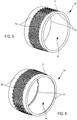
- FIG. 5 there is schematically shown an example of this application of the invention to the constitution of a hooping reinforcement directly within a tire blank 50. It is therefore this blank which served as the receiving form for the strip. corrugated prepared by the device of the invention.
- the waves of the strip extend in a plane parallel to the equatorial plane of the blank (neglecting the helix angle of the winding as discussed above). About fifteen turns were wound around the blank in order to constitute the complete hooping frame.
- the layer containing the carcass reinforcements 151 and the beads 52 containing the bead reinforcements can be placed under the hooping frame.
- a layer of sealing rubber 53 is preferably present inside the carcass 151.
- the reinforcing strips at 0 ° are shown here in the corrugated form 21 but not rolled (referenced 22 in the preceding figures) in order to facilitate reading the drawing. It is understood that the rolled shape may be preferred in order to improve the precision of the positioning of the reinforcements in the remainder of the process as described above.
- a tread and sidewall protection rubber can also be added to this blank. All the components of the future tire can thus be placed at the same reduced diameter, that is to say on the same drum with the diameter of the seat and therefore without intermediate conformation.
- the laying drum can also have a diameter slightly greater than the diameter of the seat if it includes grooves to receive the beads of the blank. Rather, we obtain a blank as shown in figure 6 .
- the assembly thus formed can then be placed in a vulcanization press, shaped and then molded and vulcanized in a manner known per se.
- feeding the device with a flat strip is subject to precise control of its flow rate.
- This can be obtained by using a motorized capstan placed upstream of the device.
- the figure 7 shows an embodiment of this capstan 100 (practically invisible on the figure 2 ).
- the flat strip 20 being guided around the pulley 101 of the capstan, the rotation of this pulley being controlled by the capstan motor 102 (visible at figure 2 ).
- a strap 103 stretched between references 104 presses the strip onto the capstan pulley in order to prevent it from slipping inadvertently.
- the speed of rotation of the capstan that is to say the speed of the flat strip feeding the device 1
- the offset between the star axis AE and the carousel axis AC can be actively adapted by means of a management based on a measurement of the voltage. effective test strip.
- this adaptation is provided passively by means for example of a simple spring 18 tending to push back the slide 15 and therefore to increase the amplitude of the waves in order to absorb the length of strip effectively delivered by the capstan.
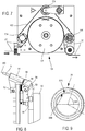
- the figures 8 and 9 show in detail an embodiment of the finger supports 51 and the control of their tilting in the interference portion.
- FIG. 8 To make the figure 8 More readable, only one support 51 is shown therein articulated by its support axis 52 on the carousel 4.
- the support axis is substantially perpendicular to the carousel axis.
- the support 51 is shown here in its disengaged position.
- a carriage 53 slides on a slide 54 and controls the pivoting of the support by means of the bush 55 slidably mounted on the tail 56 of the support.
- the movement of the carriage 53 is imposed by the rolling of a cam roller 57 on a cam surface 58, a spring (not shown) being able to ensure the return to the disengaged position.
- the grooved cam 59 shown in figure 9 imposes a support position over a range of approximately 100 ° of angle corresponding substantially to the interference portion PI. The rest of the rotation of the carousel corresponding to the two transition phases and to the release position.
Landscapes
- Engineering & Computer Science (AREA)
- Mechanical Engineering (AREA)
- Textile Engineering (AREA)
- Tyre Moulding (AREA)
Claims (17)
- Vorrichtung (1) zur Herstellung eines Verstärkungsstreifens, der zur Herstellung eines Reifens bestimmt ist, wobei die Vorrichtung ermöglicht, einen gewellten Verstärkungsstreifen (21) aus einem flachen Verstärkungsstreifen (20) herzustellen, wobei die Vorrichtung umfasst:- ein Karussell (4), das geeignet ist, mehrere Finger (5) in einer im Wesentlichen kreisförmigen Bewegung um eine Karussellachse (AC) zu führen,- einen Stern (6), der um eine Sternachse (AE) drehbar ist, wobei der drehbare Stern mehrere drehbare Rollen (7) mit zur Sternachse parallelen Achsen trägt, wobei die Rollen auf einem zur Sternachse konzentrischen Kreis (61) verteilt sind,- Mittel zur Synchronisation der im Wesentlichen kreisförmigen Bewegung der Finger und der Drehung des Sterns,- Mittel zur Führung (9, 10) des in die Vorrichtung eintretenden flachen Verstärkungsstreifens,wobei:- die Sternachse und die Karussellachse beabstandet und im Wesentlichen parallel sind, wobei die Finger geeignet sind, sich auf einer ersten Seite des Streifens abzustützen, wobei die Rollen geeignet sind, sich auf einer zweiten Seite des Streifens abzustützen,- jeder der Finger von einem Träger (51) getragen wird, der in Bezug auf das Karussell so schwenkbar ist, dass der Finger eine Anlageposition, in welcher er sich auf der ersten Seite des Streifens abstützt, und eine Freigabeposition, in welcher er sich von der ersten Seite des Streifens und von der gemeinsamen Ebene entfernt, einnehmen kann,- die im Wesentlichen kreisförmige Bewegung, in welche die Finger durch das Karussell versetzt werden, einen Interferenzabschnitt (PI) aufweist, in welchem die Mittel zur Synchronisation ermöglichen, dass sich die Finger und die Rollen in einer gemeinsamen Ebene bewegen, die zu der Sternachse senkrecht ist, wobei die Finger und die Rollen in dem Interferenzabschnitt so ineinandergreifen, dass sie dem Streifen Wellen aufzwingen, die sich in der gemeinsamen Ebene erstrecken.
- Vorrichtung nach Anspruch 1, wobei ein statischer Nocken (59) die Schwenkung der Träger der Finger in Abhängigkeit von der Winkelposition der Träger in ihrer im Wesentlichen kreisförmigen Bewegung um die Karussellachse steuert.
- Vorrichtung nach Anspruch 2, wobei der statische Nocken zwei einander gegenüberliegende Nockenflächen (58A, 58B) umfasst, wobei jede der zwei Flächen eine Schwenkrichtung der Träger kontrolliert.
- Vorrichtung nach Anspruch 2, wobei der statische Nocken zwei Nockenflächen umfasst, wobei jede der zwei Flächen eine Schwenkrichtung der Träger kontrolliert, wobei der statische Nocken die Schwenkung jedes Trägers über zwei Nockenrollen steuert, wobei jede der zwei Nockenrollen mit nur einer der zwei Nockenflächen zusammenwirkt.
- Vorrichtung nach einem der vorhergehenden Ansprüche, wobei die Finger auf einem Sektor von wenigstens 90° ihrer kreisförmigen Bewegung um die Karussellachse in ihrer Anlageposition gehalten werden, wobei der Sektor im Wesentlichen dem Interferenzabschnitt (PI) entspricht.
- Vorrichtung nach einem der vorhergehenden Ansprüche, wobei die Schwenkung der Träger der Finger in Bezug auf das Karussell um eine Trägerachse (52) erfolgt, die im Wesentlichen senkrecht zur Karussellachse (AC) ist.
- Vorrichtung nach einem der vorhergehenden Ansprüche, wobei jeder der Finger ein Rotationskörper um eine Fingerachse (AD) ist, wobei sich jeder der Finger in Bezug auf seinen Träger (51) frei um seine Fingerachse drehen kann.
- Vorrichtung nach einem der vorhergehenden Ansprüche, wobei die Mittel zur Führung Antriebsscheiben (9, 10) umfassen, die geeignet sind, den Streifen in Richtung des Interferenzabschnitts in einer zur gemeinsamen Ebene nahen Richtung zu führen.
- Vorrichtung nach einem der vorhergehenden Ansprüche, wobei das Karussell und der Stern (6) von einem Unterteil (16) getragen werden, das in Bezug auf ein festes Gestell (17) beweglich ist.
- Vorrichtung nach einem der vorhergehenden Ansprüche, welche außerdem Mittel zum Aufwalzen (70) des gewellten Streifens umfasst.
- Vorrichtung nach einem der vorhergehenden Ansprüche, welche außerdem eine Winde (100) umfasst, die geeignet ist, die Zuführung von flachen Streifen zu steuern.
- Anlage, welche die Vorrichtung (1) nach einem der vorhergehenden Ansprüche umfasst und außerdem eine drehbare Aufnahmeform (3) umfasst, die gegenüber dem Interferenzabschnitt (PI) angeordnet ist, derart, dass die Scheitel der Wellen des gewellten Streifens an der Oberfläche der Form anhaften können, um die Übertragung des gewellten Streifens auf die Form zu ermöglichen.
- Verfahren zur Herstellung eines gewellten Streifens unter Verwendung der Anlage von Anspruch 12.
- Verfahren nach Anspruch 13, wobei die Aufnahmeform aus einem Reifenrohling (50) besteht, der von einer Trommel getragen wird.
- Verfahren nach Anspruch 14, wobei mehrere Windungen des gewellten Streifens spiralförmig auf den Reifenrohling gewickelt werden, wobei sich die Wellen des Streifens in einer Ebene erstrecken, die im Wesentlichen zu einer Äquatorialebene des Rohlings parallel ist.
- Verfahren nach Anspruch 15, wobei während des Aufwickelns auf den Rohling ein Variieren der Höhe der Wellen bewirkt wird.
- Verfahren nach einem der Ansprüche 13 bis 16, wobei die Wellen des Streifens während der Übertragung des Streifens auf die Form nach und nach mithilfe der Mittel zum Aufwalzen (70) auf den Rohling umgeschlagen werden.
Applications Claiming Priority (2)
| Application Number | Priority Date | Filing Date | Title |
|---|---|---|---|
| FR1463177A FR3030349B1 (fr) | 2014-12-23 | 2014-12-23 | Dispositif et procede pour la fabrication de pneumatiques |
| PCT/EP2015/081071 WO2016102614A1 (fr) | 2014-12-23 | 2015-12-22 | Dispositif et procede pour la fabrication de pneumatiques |
Publications (3)
| Publication Number | Publication Date |
|---|---|
| EP3237190A1 EP3237190A1 (de) | 2017-11-01 |
| EP3237190B1 true EP3237190B1 (de) | 2020-12-16 |
| EP3237190B8 EP3237190B8 (de) | 2021-03-31 |
Family
ID=53483857
Family Applications (1)
| Application Number | Title | Priority Date | Filing Date |
|---|---|---|---|
| EP15821078.1A Active EP3237190B8 (de) | 2014-12-23 | 2015-12-22 | Vorrichtung und verfahren zur herstellung von reifen |
Country Status (4)
| Country | Link |
|---|---|
| EP (1) | EP3237190B8 (de) |
| CN (1) | CN107206719B (de) |
| FR (1) | FR3030349B1 (de) |
| WO (1) | WO2016102614A1 (de) |
Families Citing this family (1)
| Publication number | Priority date | Publication date | Assignee | Title |
|---|---|---|---|---|
| IT201800007455A1 (it) * | 2018-07-24 | 2020-01-24 | Processo ed un apparato per realizzare pneumatici per ruote di veicoli |
Family Cites Families (8)
| Publication number | Priority date | Publication date | Assignee | Title |
|---|---|---|---|---|
| JP3305844B2 (ja) * | 1993-12-24 | 2002-07-24 | 株式会社ブリヂストン | ゴム複合用金属コードの製造方法 |
| JP3752343B2 (ja) * | 1997-02-14 | 2006-03-08 | 横浜ゴム株式会社 | 空気入りタイヤ用カーカス構造体の製造方法及び装置並びに空気入りタイヤの製造方法 |
| DE19901958C2 (de) * | 1999-01-20 | 2001-06-13 | Continental Ag | Vorrichtung und Verfahren zur Herstellung einer Gürtelbandage eines Fahrzeugluftreifens |
| JP2002347134A (ja) * | 2001-05-29 | 2002-12-04 | Bridgestone Corp | タイヤの製造方法およびカーカスコードの貼付け装置 |
| FR2882535B1 (fr) * | 2005-02-28 | 2007-04-13 | Michelin Soc Tech | Dispositif et procede de fabrication de nappes ondulees |
| JP4866123B2 (ja) * | 2006-03-27 | 2012-02-01 | 横浜ゴム株式会社 | 空気入りタイヤの製造方法 |
| CN102056734A (zh) * | 2008-06-04 | 2011-05-11 | 株式会社普利司通 | 轮胎的制造方法和制造装置 |
| JP5319219B2 (ja) * | 2008-09-16 | 2013-10-16 | 株式会社ブリヂストン | コード製造装置及びコード製造方法 |
-
2014
- 2014-12-23 FR FR1463177A patent/FR3030349B1/fr not_active Expired - Fee Related
-
2015
- 2015-12-22 WO PCT/EP2015/081071 patent/WO2016102614A1/fr active Application Filing
- 2015-12-22 CN CN201580070217.2A patent/CN107206719B/zh active Active
- 2015-12-22 EP EP15821078.1A patent/EP3237190B8/de active Active
Non-Patent Citations (1)
| Title |
|---|
| None * |
Also Published As
| Publication number | Publication date |
|---|---|
| CN107206719B (zh) | 2019-06-18 |
| EP3237190A1 (de) | 2017-11-01 |
| CN107206719A (zh) | 2017-09-26 |
| WO2016102614A1 (fr) | 2016-06-30 |
| FR3030349A1 (fr) | 2016-06-24 |
| FR3030349B1 (fr) | 2017-01-06 |
| EP3237190B8 (de) | 2021-03-31 |
Similar Documents
| Publication | Publication Date | Title |
|---|---|---|
| EP3233457B1 (de) | Verfahren und ausrüstung zur montage eines reifenrohlings | |
| EP2707204B1 (de) | Werkzeug zum positionieren eines bandes zur herstellung eines reifenrohlings und verfahren zur realisation eines reifenrohlings | |
| EP1517781A1 (de) | Vorrichtung zur herstellung einer verstärkungsstruktur für einen reifen mit einem wulstfahnendrehmechanismus | |
| FR2999466A1 (fr) | Machine de placement de fibres comprenant un rouleau avec des bagues pivotantes | |
| EP3237190B1 (de) | Vorrichtung und verfahren zur herstellung von reifen | |
| FR3043936A1 (fr) | Tambour et procede d’assemblage d’un adaptateur de pneumatique sur une jante | |
| EP2613928B1 (de) | Verfahren und vorrichtung zur herstellung eines reifenrohlings mittels eines streifens | |
| EP2707202B1 (de) | Verfahren und vorrichtung zur herstellung einer reifenkarkassenlage | |
| EP3160724B1 (de) | Verfahren und vorrichtung zur herstellung eines reifenrohlings | |
| WO2003101714A2 (fr) | Fabrication d’une structure de renforcement pour pneumatique avec controle volumetrique de la matrice | |
| EP4076922B1 (de) | Maschine zur automatischen herstellung von luftreifen mit einer "diagonalen" krone | |
| EP3160725B1 (de) | Vorrichtung und verfahren zur reifenherstellung | |
| CH426241A (fr) | Procédé de fabrication de pneumatiques, pneumatique fabriqué selon ce procédé et appareil pour la mise en oeuvre de ce procédé | |
| FR3084279A1 (fr) | Installation de fabrication de nappes de renfort avec dispositif de retournement a plat de bandelettes | |
| EP2919980B1 (de) | Vorrichtung und verfahren zur montage der gürtellage eines reifens | |
| EP3237230B1 (de) | Vorrichtung zur abscheidung eines gewellten drahtes auf eine aufnahmefläche | |
| FR2969030A1 (fr) | Support d'assemblage d'une ebauche crue de pneumatique muni d'elements mobiles | |
| WO2016102538A1 (fr) | Dispositif et procede de depose d'un fil ondule sur une surface de reception | |
| WO2017109375A1 (fr) | Procédé et dispositif de fabrication d'un élément multicouche pour pneumatique | |
| FR3139751A1 (fr) | Procédé de fabrication sur un noyau d’un bandage pneumatique dont la carcasse comprend des renforts qui sont inclinés dans les flancs et radiaux sous le sommet | |
| EP2655051A1 (de) | Nockenträger zur montage eines reifenrohlings |
Legal Events
| Date | Code | Title | Description |
|---|---|---|---|
| STAA | Information on the status of an ep patent application or granted ep patent |
Free format text: STATUS: THE INTERNATIONAL PUBLICATION HAS BEEN MADE |
|
| PUAI | Public reference made under article 153(3) epc to a published international application that has entered the european phase |
Free format text: ORIGINAL CODE: 0009012 |
|
| STAA | Information on the status of an ep patent application or granted ep patent |
Free format text: STATUS: REQUEST FOR EXAMINATION WAS MADE |
|
| 17P | Request for examination filed |
Effective date: 20170724 |
|
| AK | Designated contracting states |
Kind code of ref document: A1 Designated state(s): AL AT BE BG CH CY CZ DE DK EE ES FI FR GB GR HR HU IE IS IT LI LT LU LV MC MK MT NL NO PL PT RO RS SE SI SK SM TR |
|
| AX | Request for extension of the european patent |
Extension state: BA ME |
|
| DAV | Request for validation of the european patent (deleted) | ||
| DAX | Request for extension of the european patent (deleted) | ||
| RAP1 | Party data changed (applicant data changed or rights of an application transferred) |
Owner name: COMPAGNIE GENERALE DES ETABLISSEMENTS MICHELIN Owner name: MICHELIN RECHERCHE ET TECHNIQUE S.A. |
|
| GRAP | Despatch of communication of intention to grant a patent |
Free format text: ORIGINAL CODE: EPIDOSNIGR1 |
|
| STAA | Information on the status of an ep patent application or granted ep patent |
Free format text: STATUS: GRANT OF PATENT IS INTENDED |
|
| INTG | Intention to grant announced |
Effective date: 20200723 |
|
| GRAS | Grant fee paid |
Free format text: ORIGINAL CODE: EPIDOSNIGR3 |
|
| GRAA | (expected) grant |
Free format text: ORIGINAL CODE: 0009210 |
|
| STAA | Information on the status of an ep patent application or granted ep patent |
Free format text: STATUS: THE PATENT HAS BEEN GRANTED |
|
| AK | Designated contracting states |
Kind code of ref document: B1 Designated state(s): AL AT BE BG CH CY CZ DE DK EE ES FI FR GB GR HR HU IE IS IT LI LT LU LV MC MK MT NL NO PL PT RO RS SE SI SK SM TR |
|
| REG | Reference to a national code |
Ref country code: GB Ref legal event code: FG4D Free format text: NOT ENGLISH |
|
| REG | Reference to a national code |
Ref country code: DE Ref legal event code: R096 Ref document number: 602015063632 Country of ref document: DE |
|
| REG | Reference to a national code |
Ref country code: IE Ref legal event code: FG4D Free format text: LANGUAGE OF EP DOCUMENT: FRENCH |
|
| REG | Reference to a national code |
Ref country code: AT Ref legal event code: REF Ref document number: 1345208 Country of ref document: AT Kind code of ref document: T Effective date: 20210115 |
|
| RAP2 | Party data changed (patent owner data changed or rights of a patent transferred) |
Owner name: COMPAGNIE GENERALE DES ETABLISSEMENTS MICHELIN |
|
| REG | Reference to a national code |
Ref country code: DE Ref legal event code: R081 Ref document number: 602015063632 Country of ref document: DE Owner name: COMPAGNIE GENERALE DES ETABLISSEMENTS MICHELIN, FR Free format text: FORMER OWNERS: COMPAGNIE GENERALE DES ETABLISSEMENTS MICHELIN, CLERMONT-FERRAND, FR; MICHELIN RECHERCHE ET TECHNIQUE S.A., GRANGES-PACCOT, CH |
|
| REG | Reference to a national code |
Ref country code: CH Ref legal event code: PK Free format text: RECTIFICATION B8 |
|
| PG25 | Lapsed in a contracting state [announced via postgrant information from national office to epo] |
Ref country code: FI Free format text: LAPSE BECAUSE OF FAILURE TO SUBMIT A TRANSLATION OF THE DESCRIPTION OR TO PAY THE FEE WITHIN THE PRESCRIBED TIME-LIMIT Effective date: 20201216 Ref country code: RS Free format text: LAPSE BECAUSE OF FAILURE TO SUBMIT A TRANSLATION OF THE DESCRIPTION OR TO PAY THE FEE WITHIN THE PRESCRIBED TIME-LIMIT Effective date: 20201216 Ref country code: NO Free format text: LAPSE BECAUSE OF FAILURE TO SUBMIT A TRANSLATION OF THE DESCRIPTION OR TO PAY THE FEE WITHIN THE PRESCRIBED TIME-LIMIT Effective date: 20210316 Ref country code: GR Free format text: LAPSE BECAUSE OF FAILURE TO SUBMIT A TRANSLATION OF THE DESCRIPTION OR TO PAY THE FEE WITHIN THE PRESCRIBED TIME-LIMIT Effective date: 20210317 |
|
| REG | Reference to a national code |
Ref country code: AT Ref legal event code: MK05 Ref document number: 1345208 Country of ref document: AT Kind code of ref document: T Effective date: 20201216 |
|
| REG | Reference to a national code |
Ref country code: NL Ref legal event code: MP Effective date: 20201216 |
|
| PG25 | Lapsed in a contracting state [announced via postgrant information from national office to epo] |
Ref country code: SE Free format text: LAPSE BECAUSE OF FAILURE TO SUBMIT A TRANSLATION OF THE DESCRIPTION OR TO PAY THE FEE WITHIN THE PRESCRIBED TIME-LIMIT Effective date: 20201216 Ref country code: LV Free format text: LAPSE BECAUSE OF FAILURE TO SUBMIT A TRANSLATION OF THE DESCRIPTION OR TO PAY THE FEE WITHIN THE PRESCRIBED TIME-LIMIT Effective date: 20201216 Ref country code: BG Free format text: LAPSE BECAUSE OF FAILURE TO SUBMIT A TRANSLATION OF THE DESCRIPTION OR TO PAY THE FEE WITHIN THE PRESCRIBED TIME-LIMIT Effective date: 20210316 |
|
| PG25 | Lapsed in a contracting state [announced via postgrant information from national office to epo] |
Ref country code: NL Free format text: LAPSE BECAUSE OF FAILURE TO SUBMIT A TRANSLATION OF THE DESCRIPTION OR TO PAY THE FEE WITHIN THE PRESCRIBED TIME-LIMIT Effective date: 20201216 Ref country code: HR Free format text: LAPSE BECAUSE OF FAILURE TO SUBMIT A TRANSLATION OF THE DESCRIPTION OR TO PAY THE FEE WITHIN THE PRESCRIBED TIME-LIMIT Effective date: 20201216 |
|
| REG | Reference to a national code |
Ref country code: LT Ref legal event code: MG9D |
|
| PG25 | Lapsed in a contracting state [announced via postgrant information from national office to epo] |
Ref country code: EE Free format text: LAPSE BECAUSE OF FAILURE TO SUBMIT A TRANSLATION OF THE DESCRIPTION OR TO PAY THE FEE WITHIN THE PRESCRIBED TIME-LIMIT Effective date: 20201216 Ref country code: CZ Free format text: LAPSE BECAUSE OF FAILURE TO SUBMIT A TRANSLATION OF THE DESCRIPTION OR TO PAY THE FEE WITHIN THE PRESCRIBED TIME-LIMIT Effective date: 20201216 Ref country code: SM Free format text: LAPSE BECAUSE OF FAILURE TO SUBMIT A TRANSLATION OF THE DESCRIPTION OR TO PAY THE FEE WITHIN THE PRESCRIBED TIME-LIMIT Effective date: 20201216 Ref country code: LT Free format text: LAPSE BECAUSE OF FAILURE TO SUBMIT A TRANSLATION OF THE DESCRIPTION OR TO PAY THE FEE WITHIN THE PRESCRIBED TIME-LIMIT Effective date: 20201216 Ref country code: PT Free format text: LAPSE BECAUSE OF FAILURE TO SUBMIT A TRANSLATION OF THE DESCRIPTION OR TO PAY THE FEE WITHIN THE PRESCRIBED TIME-LIMIT Effective date: 20210416 Ref country code: SK Free format text: LAPSE BECAUSE OF FAILURE TO SUBMIT A TRANSLATION OF THE DESCRIPTION OR TO PAY THE FEE WITHIN THE PRESCRIBED TIME-LIMIT Effective date: 20201216 Ref country code: RO Free format text: LAPSE BECAUSE OF FAILURE TO SUBMIT A TRANSLATION OF THE DESCRIPTION OR TO PAY THE FEE WITHIN THE PRESCRIBED TIME-LIMIT Effective date: 20201216 |
|
| REG | Reference to a national code |
Ref country code: CH Ref legal event code: PL |
|
| PG25 | Lapsed in a contracting state [announced via postgrant information from national office to epo] |
Ref country code: PL Free format text: LAPSE BECAUSE OF FAILURE TO SUBMIT A TRANSLATION OF THE DESCRIPTION OR TO PAY THE FEE WITHIN THE PRESCRIBED TIME-LIMIT Effective date: 20201216 Ref country code: AT Free format text: LAPSE BECAUSE OF FAILURE TO SUBMIT A TRANSLATION OF THE DESCRIPTION OR TO PAY THE FEE WITHIN THE PRESCRIBED TIME-LIMIT Effective date: 20201216 |
|
| REG | Reference to a national code |
Ref country code: BE Ref legal event code: MM Effective date: 20201231 |
|
| REG | Reference to a national code |
Ref country code: DE Ref legal event code: R097 Ref document number: 602015063632 Country of ref document: DE |
|
| PG25 | Lapsed in a contracting state [announced via postgrant information from national office to epo] |
Ref country code: IS Free format text: LAPSE BECAUSE OF FAILURE TO SUBMIT A TRANSLATION OF THE DESCRIPTION OR TO PAY THE FEE WITHIN THE PRESCRIBED TIME-LIMIT Effective date: 20210416 Ref country code: MC Free format text: LAPSE BECAUSE OF FAILURE TO SUBMIT A TRANSLATION OF THE DESCRIPTION OR TO PAY THE FEE WITHIN THE PRESCRIBED TIME-LIMIT Effective date: 20201216 |
|
| PLBE | No opposition filed within time limit |
Free format text: ORIGINAL CODE: 0009261 |
|
| STAA | Information on the status of an ep patent application or granted ep patent |
Free format text: STATUS: NO OPPOSITION FILED WITHIN TIME LIMIT |
|
| PG25 | Lapsed in a contracting state [announced via postgrant information from national office to epo] |
Ref country code: LU Free format text: LAPSE BECAUSE OF NON-PAYMENT OF DUE FEES Effective date: 20201222 Ref country code: IT Free format text: LAPSE BECAUSE OF FAILURE TO SUBMIT A TRANSLATION OF THE DESCRIPTION OR TO PAY THE FEE WITHIN THE PRESCRIBED TIME-LIMIT Effective date: 20201216 Ref country code: IE Free format text: LAPSE BECAUSE OF NON-PAYMENT OF DUE FEES Effective date: 20201222 Ref country code: AL Free format text: LAPSE BECAUSE OF FAILURE TO SUBMIT A TRANSLATION OF THE DESCRIPTION OR TO PAY THE FEE WITHIN THE PRESCRIBED TIME-LIMIT Effective date: 20201216 |
|
| 26N | No opposition filed |
Effective date: 20210917 |
|
| GBPC | Gb: european patent ceased through non-payment of renewal fee |
Effective date: 20210316 |
|
| PG25 | Lapsed in a contracting state [announced via postgrant information from national office to epo] |
Ref country code: CH Free format text: LAPSE BECAUSE OF NON-PAYMENT OF DUE FEES Effective date: 20201231 Ref country code: DK Free format text: LAPSE BECAUSE OF FAILURE TO SUBMIT A TRANSLATION OF THE DESCRIPTION OR TO PAY THE FEE WITHIN THE PRESCRIBED TIME-LIMIT Effective date: 20201216 Ref country code: LI Free format text: LAPSE BECAUSE OF NON-PAYMENT OF DUE FEES Effective date: 20201231 |
|
| PG25 | Lapsed in a contracting state [announced via postgrant information from national office to epo] |
Ref country code: GB Free format text: LAPSE BECAUSE OF NON-PAYMENT OF DUE FEES Effective date: 20210316 Ref country code: ES Free format text: LAPSE BECAUSE OF FAILURE TO SUBMIT A TRANSLATION OF THE DESCRIPTION OR TO PAY THE FEE WITHIN THE PRESCRIBED TIME-LIMIT Effective date: 20201216 |
|
| PG25 | Lapsed in a contracting state [announced via postgrant information from national office to epo] |
Ref country code: SI Free format text: LAPSE BECAUSE OF FAILURE TO SUBMIT A TRANSLATION OF THE DESCRIPTION OR TO PAY THE FEE WITHIN THE PRESCRIBED TIME-LIMIT Effective date: 20201216 |
|
| PG25 | Lapsed in a contracting state [announced via postgrant information from national office to epo] |
Ref country code: IS Free format text: LAPSE BECAUSE OF FAILURE TO SUBMIT A TRANSLATION OF THE DESCRIPTION OR TO PAY THE FEE WITHIN THE PRESCRIBED TIME-LIMIT Effective date: 20210416 Ref country code: TR Free format text: LAPSE BECAUSE OF FAILURE TO SUBMIT A TRANSLATION OF THE DESCRIPTION OR TO PAY THE FEE WITHIN THE PRESCRIBED TIME-LIMIT Effective date: 20201216 Ref country code: MT Free format text: LAPSE BECAUSE OF FAILURE TO SUBMIT A TRANSLATION OF THE DESCRIPTION OR TO PAY THE FEE WITHIN THE PRESCRIBED TIME-LIMIT Effective date: 20201216 Ref country code: CY Free format text: LAPSE BECAUSE OF FAILURE TO SUBMIT A TRANSLATION OF THE DESCRIPTION OR TO PAY THE FEE WITHIN THE PRESCRIBED TIME-LIMIT Effective date: 20201216 |
|
| PG25 | Lapsed in a contracting state [announced via postgrant information from national office to epo] |
Ref country code: MK Free format text: LAPSE BECAUSE OF FAILURE TO SUBMIT A TRANSLATION OF THE DESCRIPTION OR TO PAY THE FEE WITHIN THE PRESCRIBED TIME-LIMIT Effective date: 20201216 |
|
| PG25 | Lapsed in a contracting state [announced via postgrant information from national office to epo] |
Ref country code: BE Free format text: LAPSE BECAUSE OF NON-PAYMENT OF DUE FEES Effective date: 20201231 |
|
| PGFP | Annual fee paid to national office [announced via postgrant information from national office to epo] |
Ref country code: FR Payment date: 20231221 Year of fee payment: 9 Ref country code: DE Payment date: 20231214 Year of fee payment: 9 |