EP4076922B1 - Machine for the automatic manufacture of pneumatic tyres with a "biased" crown - Google Patents
Machine for the automatic manufacture of pneumatic tyres with a "biased" crown Download PDFInfo
- Publication number
- EP4076922B1 EP4076922B1 EP20824608.2A EP20824608A EP4076922B1 EP 4076922 B1 EP4076922 B1 EP 4076922B1 EP 20824608 A EP20824608 A EP 20824608A EP 4076922 B1 EP4076922 B1 EP 4076922B1
- Authority
- EP
- European Patent Office
- Prior art keywords
- carcass
- zone
- ply
- entity
- drum
- Prior art date
- Legal status (The legal status is an assumption and is not a legal conclusion. Google has not performed a legal analysis and makes no representation as to the accuracy of the status listed.)
- Active
Links
- 238000004519 manufacturing process Methods 0.000 title claims description 103
- 238000012546 transfer Methods 0.000 claims description 88
- 230000003014 reinforcing effect Effects 0.000 claims description 33
- 238000007493 shaping process Methods 0.000 claims description 27
- 238000004804 winding Methods 0.000 claims description 16
- 238000002360 preparation method Methods 0.000 claims description 14
- 238000009826 distribution Methods 0.000 claims description 13
- 239000013536 elastomeric material Substances 0.000 claims description 6
- 230000002787 reinforcement Effects 0.000 description 101
- 230000010287 polarization Effects 0.000 description 75
- 241001417494 Sciaenidae Species 0.000 description 24
- 235000009508 confectionery Nutrition 0.000 description 17
- 238000009434 installation Methods 0.000 description 13
- 239000000470 constituent Substances 0.000 description 7
- 238000000034 method Methods 0.000 description 7
- 230000004048 modification Effects 0.000 description 7
- 238000012986 modification Methods 0.000 description 7
- 230000008901 benefit Effects 0.000 description 6
- 230000008569 process Effects 0.000 description 6
- 230000032258 transport Effects 0.000 description 6
- 239000011324 bead Substances 0.000 description 5
- 238000005520 cutting process Methods 0.000 description 5
- 238000005096 rolling process Methods 0.000 description 5
- 238000013519 translation Methods 0.000 description 5
- 230000000694 effects Effects 0.000 description 4
- 230000005415 magnetization Effects 0.000 description 4
- 239000000463 material Substances 0.000 description 4
- 238000011144 upstream manufacturing Methods 0.000 description 4
- 238000010411 cooking Methods 0.000 description 3
- 239000002184 metal Substances 0.000 description 3
- 238000005070 sampling Methods 0.000 description 3
- 241001080024 Telles Species 0.000 description 2
- 240000008042 Zea mays Species 0.000 description 2
- 230000009471 action Effects 0.000 description 2
- 238000010276 construction Methods 0.000 description 2
- 229940082150 encore Drugs 0.000 description 2
- 230000003993 interaction Effects 0.000 description 2
- 230000000670 limiting effect Effects 0.000 description 2
- 238000012423 maintenance Methods 0.000 description 2
- 239000003607 modifier Substances 0.000 description 2
- 230000036961 partial effect Effects 0.000 description 2
- 238000012545 processing Methods 0.000 description 2
- 230000002829 reductive effect Effects 0.000 description 2
- 241000135309 Processus Species 0.000 description 1
- 238000000429 assembly Methods 0.000 description 1
- 238000007664 blowing Methods 0.000 description 1
- 238000006073 displacement reaction Methods 0.000 description 1
- 238000005265 energy consumption Methods 0.000 description 1
- 239000000446 fuel Substances 0.000 description 1
- 230000001939 inductive effect Effects 0.000 description 1
- 230000010354 integration Effects 0.000 description 1
- 238000005304 joining Methods 0.000 description 1
- 238000007726 management method Methods 0.000 description 1
- 230000007246 mechanism Effects 0.000 description 1
- 239000012528 membrane Substances 0.000 description 1
- 239000007769 metal material Substances 0.000 description 1
- 238000012856 packing Methods 0.000 description 1
- 230000001012 protector Effects 0.000 description 1
- 238000011084 recovery Methods 0.000 description 1
- 230000000284 resting effect Effects 0.000 description 1
- 230000000717 retained effect Effects 0.000 description 1
- 238000000926 separation method Methods 0.000 description 1
- 230000001360 synchronised effect Effects 0.000 description 1
- 239000004753 textile Substances 0.000 description 1
- 230000007704 transition Effects 0.000 description 1
- 239000004636 vulcanized rubber Substances 0.000 description 1
- 239000002699 waste material Substances 0.000 description 1
Images


Classifications
-
- B—PERFORMING OPERATIONS; TRANSPORTING
- B29—WORKING OF PLASTICS; WORKING OF SUBSTANCES IN A PLASTIC STATE IN GENERAL
- B29D—PRODUCING PARTICULAR ARTICLES FROM PLASTICS OR FROM SUBSTANCES IN A PLASTIC STATE
- B29D30/00—Producing pneumatic or solid tyres or parts thereof
- B29D30/06—Pneumatic tyres or parts thereof (e.g. produced by casting, moulding, compression moulding, injection moulding, centrifugal casting)
- B29D30/08—Building tyres
- B29D30/20—Building tyres by the flat-tyre method, i.e. building on cylindrical drums
- B29D30/30—Applying the layers; Guiding or stretching the layers during application
-
- B—PERFORMING OPERATIONS; TRANSPORTING
- B29—WORKING OF PLASTICS; WORKING OF SUBSTANCES IN A PLASTIC STATE IN GENERAL
- B29D—PRODUCING PARTICULAR ARTICLES FROM PLASTICS OR FROM SUBSTANCES IN A PLASTIC STATE
- B29D30/00—Producing pneumatic or solid tyres or parts thereof
- B29D30/06—Pneumatic tyres or parts thereof (e.g. produced by casting, moulding, compression moulding, injection moulding, centrifugal casting)
- B29D30/08—Building tyres
- B29D30/20—Building tyres by the flat-tyre method, i.e. building on cylindrical drums
- B29D30/24—Drums
- B29D30/26—Accessories or details, e.g. membranes, transfer rings
- B29D30/2607—Devices for transferring annular tyre components during the building-up stage, e.g. from the first stage to the second stage building drum
-
- B—PERFORMING OPERATIONS; TRANSPORTING
- B29—WORKING OF PLASTICS; WORKING OF SUBSTANCES IN A PLASTIC STATE IN GENERAL
- B29D—PRODUCING PARTICULAR ARTICLES FROM PLASTICS OR FROM SUBSTANCES IN A PLASTIC STATE
- B29D30/00—Producing pneumatic or solid tyres or parts thereof
- B29D30/0061—Accessories, details or auxiliary operations not otherwise provided for
-
- B—PERFORMING OPERATIONS; TRANSPORTING
- B29—WORKING OF PLASTICS; WORKING OF SUBSTANCES IN A PLASTIC STATE IN GENERAL
- B29D—PRODUCING PARTICULAR ARTICLES FROM PLASTICS OR FROM SUBSTANCES IN A PLASTIC STATE
- B29D30/00—Producing pneumatic or solid tyres or parts thereof
- B29D30/06—Pneumatic tyres or parts thereof (e.g. produced by casting, moulding, compression moulding, injection moulding, centrifugal casting)
- B29D30/08—Building tyres
- B29D30/20—Building tyres by the flat-tyre method, i.e. building on cylindrical drums
- B29D30/22—Breaker plies being applied in the unexpanded state
-
- B—PERFORMING OPERATIONS; TRANSPORTING
- B29—WORKING OF PLASTICS; WORKING OF SUBSTANCES IN A PLASTIC STATE IN GENERAL
- B29D—PRODUCING PARTICULAR ARTICLES FROM PLASTICS OR FROM SUBSTANCES IN A PLASTIC STATE
- B29D30/00—Producing pneumatic or solid tyres or parts thereof
- B29D30/06—Pneumatic tyres or parts thereof (e.g. produced by casting, moulding, compression moulding, injection moulding, centrifugal casting)
- B29D30/08—Building tyres
- B29D30/20—Building tyres by the flat-tyre method, i.e. building on cylindrical drums
- B29D30/30—Applying the layers; Guiding or stretching the layers during application
- B29D2030/3064—Details, accessories and auxiliary operations not otherwise provided for
Definitions
- the present invention relates to the field of manufacturing pneumatic tires.
- An automatic tire manufacturing machine is described, for example, in the document WO 2018/096511 A1 .
- first annular block which comprises at least one carcass ply containing reinforcing wires which extend along radial planes relative to the central axis of the tire, and which is shaped, preferably by inflation, so as to have a toroidal shape
- second annular block which comprises a tread, as well as layers reinforcement, called “top layers”, which each have reinforcing wires arranged parallel to each other and obliquely relative to the circumferential direction of the bandage, at an angle called “ply angle”.
- Such a tire architecture called “radial carcass” has numerous advantages, particularly in terms of road holding.
- the conformation parameters as well as the initial orientation of the reinforcing wires of the carcass ply and the second ply, here preferably a top ply, it is possible to control the rotation of the direction of the reinforcing wires respective of each ply, and thus to obtain, after conformation, the final angular orientation desired for the different reinforcing wires.
- Another advantage is that the interaction between reinforcing threads belonging to two distinct layers, interaction which is due to the crossing of said reinforcing threads created by the superposition and joining of the layers, occurs, and causes a modification of orientation of the direction of said reinforcing wires, mainly or even exclusively in the covering zone, and little, if any, outside of said covering zone.
- the objects assigned to the invention therefore aim to remedy the aforementioned drawbacks and propose a new bandage manufacturing machine which allows efficient production of bandages having a polarized top architecture.
- the machine according to the invention makes it possible to carry out, in a limited time and in a reduced space, all of the operations making it possible to constitute a bandage having a polarized vertex architecture.
- the tire from the machine is preferably a raw rubber-based tire, ready to be sent to cooking to be vulcanized.
- the proximity of the manufacturing, finishing and assembly zones advantageously limits the footprint of the machine according to the invention as well as the amplitude of the transfer movements of the different constituent blocks of the tire, which makes it possible to reduce the cycle time and energy consumption of said machine.
- the automation of the manufacturing process, and the simultaneous realization of the manufacturing steps of different constituent elements of the tire, in this case the crown block on the one hand and the carcass block on the other hand, makes it possible to optimize said cycle time.
- the modular architecture of the proposed machine makes it possible in particular to exploit certain mechanical sub-assemblies already known and proven, particularly in terms of producing the carcass block and/or producing the top block, which contributes to good reliability. of the machine, and simplifies the integration of said machine within workshops and its handling by operators.
- the machine according to the invention can advantageously present great versatility, insofar as it is possible to configure said machine in such a way that it can produce both tires having a radial carcass architecture and tires having an architecture with polarized top.
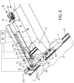
- the invention relates to a machine 1, as illustrated in particular on the figures 1 , 3 And 6 , which is intended for the automatic manufacture of a tire, and more preferably for the automatic manufacture of a pneumatic tire.
- Said machine 1 comprises a first zone 2, called “constructing zone” 2, arranged to produce a first annular block 3 constituting the tire, called “carcass block” 3, which comprises at least one carcass ply 4 provided with a first set of wire reinforcement elements 5, called “carcass reinforcements” 5, as is particularly visible on the figures 2 , 4 And 7 .
- wire is meant an element extending longitudinally along a main line and which has a section perpendicular to said main line whose largest dimension, called “transverse dimension” G, is relatively small compared to the dimension called " longitudinal dimension » L considered along said main line.
- transverse dimension G
- L longitudinal dimension » L considered along said main line.
- relatively low we mean that the L/G ratio is greater than or equal to 100, preferably greater than or equal to 1000.
- This definition covers both wire elements of circular section and wire elements of non-circular section, for example example of polygonal or oblong section.
- each wire element has a circular section.
- the carcass ply 4 is preferably formed, in a manner known per se, from a ply of elastomeric material, preferably based on raw rubber, that is to say unvulcanized rubber, in which the carcass reinforcements 5.
- said carcass reinforcements 5 extend in length parallel to each other and each continuously from a side edge of said carcass ply 4 to the opposite side edge.
- the carcass reinforcements 5 have a stiffness, that is to say a tensile strength modulus, which is strictly greater than the tensile modulus of the raw rubber constituting the ply, and more generally greater than the tensile modulus of the vulcanized rubber. , so as to give the carcass ply 4 a quasi-inextensible character in the direction of the length of said carcass reinforcements 5.
- the carcass reinforcements 5 may be formed by wires or cables of any suitable material, preferably of textile material or of metallic material.
- the manufacturing zone 2 comprises a manufacturing drum 6, which has a central drum axis X6 and which is mounted to rotate around said central drum axis X6.
- Said drum 6 is thus carried by, and mounted in rotation on, a drum frame 7, preferably cantilevered relative to said drum frame 7.
- Said drum frame 7 preferably comprises a drive motor, preferably electric, making it possible to drive the drum 6 in rotation around its central axis X6.
- the manufactured drum 6 has, at least initially during the installation of the carcass ply 4, a receiving surface, preferably cylindrical with a circular base, which forms a surface of revolution around the central axis X6 of the drum , and which is intended to receive the components of the carcass block 3.
- a receiving surface preferably cylindrical with a circular base, which forms a surface of revolution around the central axis X6 of the drum , and which is intended to receive the components of the carcass block 3.
- the manufacturing zone 2 also includes a first feed system 10 which is arranged to place a carcass sheet 4 on the manufacturing drum 6 by winding on said manufacturing drum 6, around the central axis of the drum X6, and this so that the carcass reinforcements 5 have, relative to a circumferential direction C6 of the drum, a first angular orientation A5_1.
- the first feed system 10 may in particular comprise a conveyor belt 13, which extends transversely to the central axis of the drum X6 and which opens opposite said drum 6.
- circumferential direction here more precisely by “circumferential direction C6 of the drum”, we mean the direction which, at the point considered, is substantially perpendicular to both the axial reference direction considered, that is to say here perpendicular to the direction of the central axis of the drum
- the circumferential direction C6 of the drum corresponds here to the fictitious curve, preferably a circle, with regard to the preferably circular section of the drum 6, such that said fictitious curve is defined by the intersection of the cylindrical receiving surface of the drum 6, which receives the constituents of the carcass block 3, with a gauge plane normal to the central axis X6 of the drum.
- the circumferential direction C6 thus corresponds, at any point considered on the circumference of the drum, to the ortho-radial vector which defines the tangent to said circumference of the drum at the point considered, in said gauge plane.
- said gauge plane corresponds to the equatorial plane P_EQ of the tire, and more particularly to the equatorial plane of the carcass block 3, centered axially with respect to the carcass block 2, and which thus axially subdivides said carcass block 3 into two substantially symmetrical hemispheres, of the same axial height, such that the circumferential direction C6 substantially coincides with the equatorial line of the carcass block 3.
- the carcass reinforcements 5 initially extend, during the “flat” laying of the carcass ply 4 on the drum 6, before shaping, along radial planes which contain the central axis X6 of the drum.
- the carcass reinforcements 5 thus extend preferably parallel to the central axis X6, as is particularly visible on the figures 13 and 14 .
- the first angular orientation A5_1 corresponds in this case to a perpendicular orientation, the carcass reinforcements 5 in fact forming an angle of 90 degrees (or substantially 90 degrees, for example between 85 and 95 degrees) relative to the circumferential direction C6 .
- first angular orientation A5_1 according to which the carcass reinforcements 5 would initially be arranged obliquely with respect to the circumferential direction C6, as is the case at purely illustrative title on the Figure 18 , for example by forming, before conformation, an angle of between 27 and 150 degrees, preferably between 56 degrees and 123 degrees with respect to said circumferential direction C6.
- the carcass reinforcements 5 extend parallel to each other, and are each axially continuous, from a first edge 4L forming, with reference to the axial direction of the drum X6, an axial end from the carcass ply 4 to a second edge 4R forming the opposite axial end of said carcass ply 4.
- each material constituting the reinforcing wire element and therefore more generally said reinforcing wire element, here in particular each carcass reinforcement 5, extends in an uninterrupted manner, preferably by a in one piece, over the entire length of said reinforcing wire element.
- the carcass reinforcements 5 will be able to connect two annular rods 11, 12 to each other.
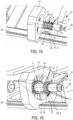
- Said annular rods 11, 12, preferably made from metal wire braids, will be integrated into the carcass block 3, concentrically with the central axis of the drum X6, as is visible on the Figure 15 , to subsequently allow the tire to be attached to a rim.
- each of said rods 11, 12 will be attached to the carcass block 3 in the form of a sub-assembly called “heel block” which comprises said rod 11, 12 as well as a rubber ring, not represented here, which is called “bead packing”, which has a substantially triangular transverse section, and whose radially internal base is arranged to press against or even surround the section of the bead 11, 12 in the bead zone through which the tire comes resting on the rim.
- the manufacturing zone 2, and more preferably the first feed system 10, will of course be arranged to place other possible components of the carcass block 3 on the drum.
- the first supply system 10 will preferably make it possible to wind on the drum 6, prior to the installation of the carcass ply 4, a film called “inner rubber”, which is intended to ensure watertightness. air from the bandage.
- the first feed system 10 could be designed to place and wind on the drum 6, around the central axis X6, a “complex” (not shown), that is to say a subassembly which will have been, to reduce the cycle time of the machine 1, pre-assembled before being brought to the drum 6, and which will include for example the inner rubber, as well as two strips of rubber covering the lateral portions of said inner rubber and intended to form the outer sides of the tire, and, possibly, rubber cushions called “bead protectors”, intended to reinforce the beads of the tire at the level of the beadings 11, 12.
- a “complex” not shown
- a subassembly which will have been, to reduce the cycle time of the machine 1, pre-assembled before being brought to the drum 6, and which will include for example the inner rubber, as well as two strips of rubber covering the lateral portions of said inner rubber and intended to form the outer sides of the tire, and, possibly, rubber cushions called “bead protectors”, intended to reinforce the beads of the tire at the level of the bea
- the carcass layer 4 will then be placed on the drum 6, over said complex.
- the machine 1 also includes a second zone 20, called “finishing zone” 20, arranged to produce a second annular block 21 constituting the tire, called “top block” 21, which comprises at least one tread 22.
- Said finishing zone 20 comprises for this purpose a ferrule 23 mounted to rotate around a central axis around the central axis of ferrule X23, as illustrated on the Figure 12 .
- the ferrule 23 is carried, preferably cantilevered, by a ferrule frame 25, capable of driving said ferrule 23 in rotation around its central axis X23.
- Said shell frame 25 is provided for this purpose with a drive motor, preferably an electric motor.
- the ferrule 23 will preferably have a receiving surface having a shape of revolution around the central axis of the ferrule to receive the components of the top block 21.
- the central axis of the shell X23 will be parallel to the central axis of the drum X6.
- the common direction, parallel to these two central axes X6, X23 will define, by convention, a global axial direction of machine 1.
- finishing zone 20 will include, if necessary, the equipment 26, 27 necessary to place the various other constituent components of the top block 21 by winding on the ferrule 23.
- the finishing zone 20 may include truncation equipment, designed to place on the ferrule 23, before the installation of the tread 22 and therefore radially under said tread 22, a strapping ring, said hoop being obtained by winding a continuous reinforced strip in a helix around the central axis of ferrule X23, in several consecutive contiguous turns.
- the reinforced strip used to make the hoop will contain continuous hoop reinforcements, which extend parallel to each other and parallel to the longitudinal direction of said reinforced strip so that, ultimately, said hoop reinforcements are will be found in the top block 21, and more generally in the bandage, oriented relative to the circumferential direction C6 at an angle which corresponds to the helix angle of the turns of said hoop, and which is relatively weak, for example less than or equal to 5 degrees, so that said reinforcements extend substantially in the circumferential direction.
- the installation of the hoop within the finishing zone 20 will be carried out by choosing, during transcanning, a helix angle which will preferably be less than or equal to 10 degrees, preferably less than or equal to 7 degrees , and more preferably less than or equal to 5 degrees.
- the equipment 26, 27 of the finishing zone may include several delivery systems if necessary, as is visible in particular on the figures 1 , 2 , 3 , 6 Or 7 , each delivery system being capable of conveying at least one of the constituents of the top block 21 to the ferrule 23.
- the equipment in particular the feed systems, 24, 26, 27, can be staged axially and/or vertically at the level of the finishing zone 20, for good compactness of the together.
- the ferrule frame 25 can then be provided with a movement mechanism allowing it to move horizontally (along the ferrule axis X23) and/or vertically so that said ferrule frame 25 can come to present the ferrule 23 successively opposite the different equipment and supply systems 24, 26, 27, in order to collect the different constituents of the top block 21 in the desired order.
- the machine 1 further comprises a shaping system 30, arranged to carry out a shaping operation which causes a radial expansion of the carcass block 3 present on the manufacturing drum 6, in order to obtain a so-called “shaped” carcass block 3, of toroidal shape, as visible on the Figure 16 .
- Such a conformation system 30 essentially makes it possible to bring the first rod 11 and the second rod 12 axially closer to each other, while pushing back radially, according to a centrifugal radial expansion movement relative to the central axis the final shape of the bandage. In doing so, a circumferential expansion of the carcass block 3 is also caused, along the circumferential direction C6.
- said conformation system 30 will make it possible to pass the carcass block 3 from a retracted configuration, preferably cylindrical with a circular base, which corresponds to the "flat" configuration according to which the inner rubber and the carcass ply 4 are initially placed by winding on the drum 6, in an deployed configuration, in which said carcass block 3 has a toroidal shape, convexed radially outwards, which preferably corresponds substantially to the shape that said carcass block 3 will adopt within the tire finished.
- the conformation system 30 operates by inflation, so as to produce the expansion of the carcass block 3 by blowing, inside the sealed cavity which is delimited by the wall formed by the constituent layers of the carcass block 3, and more particularly by the wall formed by the interior rubber, a gas, for example air, under a predetermined pressure, called “conformation pressure”, greater than the ambient atmospheric pressure.
- a gas for example air
- conformation pressure a predetermined pressure
- the machine 1 also includes a third zone 40 called "assembly zone" 40, which is arranged to assemble the top block 21 concentrically on the shaped carcass block 3, as illustrated in the figure. Figure 17 , in order to obtain a bandage.
- the top block 21, closed in a ring on itself during its manufacture on the ferrule 23, is threaded axially along and around the drum 6 carrying the carcass block 3.
- This partial retraction allows the carcass block 3 to maintain a toroidal shape, in an intermediate expansion configuration in which said carcass block 3 has an overall radius which has an intermediate value strictly between on the one hand the base radius of the drum which corresponds to the retracted “flat” configuration for laying the carcass ply 4 and on the other hand a maximum radius which corresponds to the deployed conformation configuration, in which the carcass block 3 is fully expanded.
- This partial retraction can be obtained by slightly releasing the inflation pressure applied by the conformation system 30, to bring the inflation pressure to an intermediate level between the ambient atmospheric pressure and the conformation pressure, said intermediate level being called “pressure d 'introduction', and by (slightly) increasing the distance which axially separates the two rods 11, 12 from one another.
- top block 21 engaged and superimposed on the carcass block 3
- rolling can be carried out to press, substantially radially, said top block 21 on the carcass block 3, in order to ensure good cohesion between the two blocks 21, 3 , in particular at the level of the shoulders of the tire, where the lateral ends (wings) of the tread 22 come to match the sides of the carcass block 3.
- the assembly zone 40 comprises a transfer device 41, of the transfer ring type 41, which is arranged to receive the top block 21 coming from the ferrule 23 of the finishing zone 20, such as this is illustrated on the figure 13 , and to transfer said top block 21 onto and around the shaped carcass block 3, as is illustrated successively on the figures 14 And 17 .
- the transfer device 41 is preferably formed by a transfer ring 41, and can therefore be compared to such a transfer ring 41 in the following.
- Said transfer ring 41 is advantageously coaxial with the manufacturing drum 6, so that the drum 6, carrying the carcass block 3, can slide inside said transfer ring 41, carrying the top block 21, by a movement of ruzement in axial translation, in a direction parallel, and preferably collinear, to the central axis X6 of the drum 6.
- the transfer ring 41 preferably ensures gripping of the crown block 21 from the outside, by engaging on the radially external surface of the tread 22, preferably in several angular sectors which, to ensure a balanced grip and stable, are preferably distributed over at least 180 degrees, at least 270 degrees, or even 360 degrees around the central axis X41 of said transfer ring 41.
- transfer ring 41 grips, for example, the top block 21 by a system of suction cups.
- the transfer ring 41 will grip the top block 21 by means of a plurality of jaws 45 which are mounted movable radially and distributed in azimuth, substantially in a star shape, around the central axis X41 of said transfer ring, so as to be able to come into centripetal support simultaneously on the summit block 21 in distinct and substantially concurrent directions.
- the maintenance of the crown block 21 in the transfer ring 41 can be ensured mechanically, by constriction, by taking advantage of the intrinsic rigidity of the closed annular structure of said crown block 21.
- the ferrule frame 25 brings together and axially threads the ferrule 23 into the transfer ring 41, the central axis of which X41 is then preferably confused with the central axis X23 of said ferrule, as is visible on the figure 13 .
- the ferrule 23 is released axially by an axial recoil movement of the ferrule frame 25, as is illustrated in the Figure 14 .
- the drum frame 7 can then be moved to axially engage the drum 6 in the transfer ring 41, preferably from the side opposite to that used to engage the ferrule 23, so that the transfer ring 41 can apply the top block 21 in radial superposition on, and all around, the carcass block 3, as illustrated in the Figure 17 .
- the central axis X41 of the transfer ring 41 is then preferably coincident with the central axis X6 of the drum.
- the arrangement of the shroud 23 cantilevered, here projecting axially, relative to the shroud frame 25, as well as the arrangement of the drum 6 cantilevered, here projecting axially. , relative to the drum frame 7, facilitates the alternative introduction of the ferrule 23, then respectively, of the drum 6, inside the transfer ring 41.
- the transfer ring 41 is itself movable, in particular in axial translation, guided parallel to the respective central axes of the ferrule X23 and the drum X6, so as to be able to ensure at least part of the displacement necessary to pass from the ferrule 23 to the drum 6, and more particularly to axially transfer the top block 21 from the finishing zone 20 to the assembly zone 40.
- the transfer ring 41 will be stationary, so as to occupy a predetermined fixed position in the assembly zone 40, relative to the frame of reference in which the machine 1 is located (typically the floor of the building). , while it is the shell frame 25, respectively the drum frame 7, which will form mobile elements and will carry out the necessary movements, here more particularly the necessary axial movements, with respect to the installation reference frame, and therefore with respect to the transfer ring 41, to be placed alternately within said transfer ring 41, respectively from the finishing zone 20 and from the manufacturing zone 2.
- a fixed transfer ring 41 preferably placed in a substantially central position relative to the drum 6 and the ferrule 23, will make it possible to easily and reliably and reproducibly take a photo. machine origin in relation to said transfer ring 41, and thus to use a common reference frame to carry out the different movements of the drum frame 7 and the shell frame 25.
- the manufacturing drum 6, here more particularly the drum frame 7, the transfer device 41, here the ring transfer 41, and the ferrule 23, here more particularly the ferrule frame 25, are aligned in this order along the same main guide rail 42, preferably rectilinear, so that the ferrule 23, here more particularly the ferrule frame 25, can move back and forth along said main guide rail 42 from the finishing zone 20 to the assembly zone 40 to deposit the top block 21 in the transfer device 41, while the making drum 6, here more particularly the drum frame 7 can come and go from the manufacturing zone 2 to the assembly zone 40 to present the carcass block 3 shaped in the transfer device 41, facing each other, axially , of the top block 21 contained in said transfer device 41.
- Such an arrangement advantageously makes it possible to place the assembly zone 40, and the transfer device 41, in a central position, while the operations of making on the one hand, that is to say manufacturing the carcass block 3, and finishing on the other hand, that is to say manufacturing the top block 21, are distributed in the “wings” of the machine 1, on either side of the assembly zone 40, respectively in a first manufacturing zone 2 located axially, along the main guide rail 42, on a first side of the assembly zone 40 and the transfer device 41, and in a second finishing zone 20 located, axially, on a second side of the assembly zone 40 and the transfer device 41, opposite the first side.
- Such a well-balanced spatial distribution makes it possible, on the one hand, to distribute the manufacturing tasks of the different blocks 3, 21 constituting the tire, and thus to reduce the cycle time by carrying out certain tasks in hidden time, as will be explained later. low, and on the other hand to limit the amplitude of the movements of the drum frames 7 and shell 25, which saves time and energy.
- the alignment (in this order) of the manufacturing 2, assembly 40 and finishing 20 zones in a common direction materialized by the main guide rail 42 advantageously makes it possible to achieve a rational and compact arrangement of the machine 1 , within which the supply systems 10, 24, 26, 27, 70 responsible for supplying the components necessary for the manufacture of the carcass 3 and top 21 blocks can advantageously extend, as is visible on the figures 1 , 3 And 6 , transversely to the direction of the main guide rail 42, and more preferably perpendicular to the direction of the main guide rail 42, preferably in directions parallel to the horizontal.
- the supply and maintenance operations of the machine 1 are advantageously simplified.
- the direction of the guide rail 42 is parallel to the central axis of the drum X6, and, more generally, to the central axis X23 of the ferrule and to the central axis X41 of the transfer ring, and thus materializes the axial (global) direction of machine 1.
- the machine 1 comprises a polarization system 50 which is arranged to bring into contact with the carcass block 3, before the shaping operation, an annular structure called “polarization structure” 51, which is centered on the central axis of the drum X6 and provided with a second set of wire reinforcement elements 52, called “reinforcements of polarization » 52, which have, relative to the circumferential direction of the drum C6, a second angular orientation A52_1, which is different from the first angular orientation A5_1 of the carcass reinforcements 5.
- polarization structure which is centered on the central axis of the drum X6 and provided with a second set of wire reinforcement elements 52, called “reinforcements of polarization » 52, which have, relative to the circumferential direction of the drum C6, a second angular orientation A52_1, which is different from the first angular orientation A5_1 of the carcass reinforcements 5.
- Said polarization structure 51 thus brought and positioned by the polarization system 50 extends so as to partially overlap the carcass ply 4 along the central axis of the drum although during the shaping operation, the polarization reinforcements 52 interact with the carcass reinforcements 5 in order to modify, in the covering zone 53, the angular orientation of said carcass reinforcements 5 relative to the circumferential direction of the drum C6, so that we obtain a shaped and polarized carcass block 3.
- the polarization reinforcements 52 preferably extend parallel to each other, and preferably continuously from one axial end to the other axial end of the covering zone 53, and more generally from one axial end to the other of the polarization structure 51.
- polarized we designate an object or a structure, here the carcass layer 4 and more generally the carcass block 3 as a whole, which results from a polarization operation within the meaning of the invention.
- a "polarization" operation consists of overlapping part of a carcass ply containing wire reinforcing elements called “carcass reinforcements” with a structure of polarization 52 containing polarization reinforcements 52, so that said reinforcements cross and can thus interact in order to mutually reorient under the effect of the conformation.
- the carcass sheet 4 and the polarization structure 51 will be linked in a sufficiently secure manner to one another, at least before and during the shaping operation, so that they do not slide freely one by one. relative to each other, and that their respective reinforcements 5, 52 can thus interact, in the manner of the meshes (here parallelepiped) of a mesh network, the nodes of which correspond to the virtual crossings of said reinforcements 5, 52 (considered in projection on the surface of the covering zone 53).
- the covering zone 53 corresponds to a central portion of the carcass ply 4, which is located at a distance from each of the axial ends 4L, 4R of said carcass ply 4, and which is intended to be found under the tread 22, between the shoulders of the bandage.
- the lateral portions of the carcass ply 4, not covered by the polarization structure 51 and therefore located outside the covering zone 53, are advantageously intended to form the left flanks S3_L and right S3_R of the carcass block 3 and more generally of the tire.
- Said sides correspond, in a manner known per se, to the portions of the carcass block 3, and more generally of the tire, intended to straighten out substantially radially during the shaping operation to each connect a rod 11, 12 to the most shoulder. close, to the corresponding axial end of the tread 22.
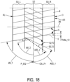
- the polarization operation causes the carcass reinforcements 5 located on the expanded cylindrical surface of the carcass block 3, thereby modifying the angular orientation of said carcass reinforcements 5 relative to the circumferential direction C6, as is illustrated in dotted line on the Figure 18 , so as to give said carcass reinforcements 5 a third angular orientation A5_2, distinct from the first angular orientation A5_1, said polarization operation does not however affect, or substantially not, the edges of the carcass ply 4 forming the sides S3_L , S3_R, not covered by the polarization structure 51, and therefore located outside the covering zone 53.
- the action of the carcass reinforcements 5 on the polarization reinforcements 52 during the conformation operation reorients said polarization reinforcements to move them from the second angular orientation A52_1 to a fourth angular orientation A52_2 different from said second angular orientation A52_1, as illustrated in the Figure 18 .
- the shaping operation tends to "radialize" the carcass reinforcements 5, that is to say to substantially align said carcass reinforcements 5 on radial planes containing the axis of the drum were not already initially arranged parallel to said drum axis X6, during the installation of the carcass ply 4.
- the first rod 11 can be carried by a first cradle of the drum 6 and the second rod by a second cradle of the same drum 6, mounted in free rotation relative to the first cradle, around the drum axis X6.
- the polarization located in the covering zone 53, as it is operated according to the invention, allows the carcass block 3, and therefore more generally the tire, to adopt a polarized reinforcement architecture under its top, while retaining a radial reinforcement architecture in its sides.
- the machine comprises an automatic control unit 60, for example an electronic control unit 60, which comprises at least one program making it possible to automatically cause the machine 1 to execute a cycle, called a "bandage manufacturing cycle".
- polarized top which comprises a step (a) of producing a top block 21 in the finishing zone 20, a step (b) of preparing a shaped and polarized carcass block 3 which comprises a sub-step (b1 ) producing a carcass block 3 in the manufacturing zone 2 then a sub-step (b2) of conformation and polarization during which said carcass block 3 coming from the manufacturing zone is shaped and polarized 2 to obtain a shaped and polarized carcass block 3, said cycle providing that step (a) of producing the top block 21 overlaps temporally at least in part with step (b) of preparing the carcass block 3, so that at least part of the production of the top block 21 takes place in hidden time compared to the preparation of the carcass block 3, then finally a step (c) assembly during which, in the assembly zone 40,
- control unit 60 is programmed so that step (a) of producing the top block 21, which takes place in the finishing zone 20, and during which said top block 21 is manufactured by placing on the ferrule 23 the component(s) of said top block 21, among which the tread 22, overlaps temporally at least in part with the sub-step (b1) of producing the carcass block 3, which takes place in the manufacturing zone 2, and during which said carcass block 3 is manufactured, here preferably "flat", by placing on the drum 6 the components of said carcass block 3, including the carcass ply 4.
- control unit 60 which automatically ensures centralized and synchronized management of the different zones 2, 20, 40 and the different systems 6, 7, 10, 23, 25, 24, 30, 41, 50 of the same machine 1 makes it possible to optimize the progress of the above-mentioned steps, and in particular to execute simultaneously, at least in part, on the one hand the preparation of a carcass block 3, and on the other hand the manufacture of a top block 21 intended to integrate the same tire as said carcass block 3.
- the machine 1 can thus automatically manufacture a top block 21 in the finishing zone 20 and place said top block 21 waiting in the transfer ring 41, while moreover, at least partly in the same interval of time, it manufactures, then conforms and polarizes on the drum 6, a carcass block 3, which it then threads, with the drum 6, into the transfer ring 41 so that said carcass block 3 receives, on its radially external surface , said summit block 21.
- the preparation of a shaped and polarized carcass block 3, in the manufacturing zone 2 can in practice be longer than the production of the corresponding top block 21 in the finishing zone 20, so that it is generally the summit block 21 which is completed first and placed on hold in the transfer ring 41, awaiting the end of the manufacturing, conformation and polarization process of the carcass block 3.
- the automatic sequence of the above-mentioned steps will make it possible to automatically produce a bandage during a cycle then, as soon as said bandage is evacuated for cooking, to start the same cycle again to automatically produce a second bandage, and and so on.
- the machine 1 preferably comprises, as is visible in particular on the figures 1 , 3 , And 6 , a third feed system 70 which is arranged to bring a ply called "top ply” 71, which top ply 71 is intended to integrate the tire between the carcass ply 4 and the tread 22 to reinforce said tire.
- said top sheet 71 comprises a layer of elastomeric material which extends, in a longitudinal direction L71, from a head end 71F to a tail end 71R, and within which are located wire reinforcing elements 72, called “top ply reinforcements” 72, which are arranged parallel to each other at an angle called “top ply angle” predetermined relative to the longitudinal direction L71, as is particularly visible on THE figures 1 And 15 .
- Said top ply reinforcements 72 each extend continuously from a side edge of the top ply 71 to the axially opposite side edge of said top ply 71.
- the longitudinal ends 71F, 71R of the top ply 71 form bevels, the cutting direction of which corresponds to the oblique direction of the angle of the top ply, so that the edges of said bevels are parallel to the reinforcements of summit tablecloth 72.
- top ply reinforcements 72 are superimposed by crossing with the carcass ply reinforcements 5, and where appropriate with a third family of reinforcements which are contained in a hoop (not shown) of the top block 21 and oriented substantially in the circumferential direction C6, so that these three types of superimposed and crossed reinforcements form, as a whole, a triangular reinforcement structure.
- the top ply reinforcements 72 are formed by metal wires or cables based on metal wires.
- the polarization system 50 may use as polarization structure 51 a polarizing sleeve, which contains the polarization reinforcements 52 and which is an integral part of the manufacturing drum 6 on which we come place the carcass ply 4, so that said polarizing sleeve can act as a reusable polarization structure 51, which temporarily interacts with the carcass block 3 when a radial expansion of the manufactured drum 6 is carried out to carry out the operation conformation, then which is separated from the bandage when said bandage is removed from the manufacturing drum 6.
- the top sheet 71 will preferably be integrated into the top block 21, and not into the carcass block 3, so as not to interfere with the action of the polarizing sleeve 51 of the drum 6 when the expansion is carried out. of said drum 6 to cause the conformation and polarization of the carcass ply 4, in the covering zone 53.
- top ply 71 will be integrated initially into the top block 21, then finally placed on the carcass ply 4 and the carcass block 3 at the same time as the rest of the top block 21, after conformation and polarization of said carcass block 3.
- the polarization system 50 with a reusable sleeve could for example correspond to the Figure 14 , if we considered that, on this Figure 14 , the dotted lines of the polarization structure 51 would here correspond to the axial limits of an underlying polarization sleeve, which would envelop the expandable surface of the drum 6, under the zone covering 53 of the carcass ply 4.
- Such a polarization sleeve would preferably be in the form of a tubular elastic membrane, engaged on the drum 6, and within which the polarization reinforcements 52 would be located.
- the polarization system 50 will this time use the top sheet 71 itself as a polarization structure 51, so that the reinforcements of top layer 72 form the polarization reinforcements 52.
- the third feed system 70 will then be arranged for this purpose to bring the top ply 71 into the manufacturing zone 2 and wind said top ply 71 on the manufacturing drum 6 until closing the tail end 71R of said ply top 71 on the head end 71F of this same top ply 71, so as to integrate said top ply 71 into the carcass block 3, before the shaping operation.
- the polarized portion of the carcass ply 4, under the top of the tire, in the covering zone 53, can replace one of the necessary top plys, since the carcass reinforcements 5 thus oriented obliquely relative to the circumferential direction C6 may overlap and intersect with the reinforcements 72 of the top ply 71 on the one hand, and with the circumferential reinforcements of the hoop on the other hand, to form triangular reinforcement structures. It will thus be possible to advantageously use only one top layer 71 instead of two top layers to constitute the bandage.
- the longitudinal direction L71 of said top ply 71 merges with the circumferential direction C6 of the drum 6 and the carcass block 3.
- the sheet angle formed by the top sheet reinforcements 72 with respect to the longitudinal direction L71 of the top sheet coincides with the angular orientation, and more particularly with the second angular orientation A52_1, of the polarization reinforcements 52.
- the covering zone 53 corresponds to the portion of the carcass ply 4 covered by the top ply 71, and therefore coincides in practice with the (complete) surface extent of said top ply. 71, while the sides S3_L, S3_R of the carcass block 3, which will not be subject to the polarization phenomenon, correspond to the portions of the carcass ply 4 not covered by the top ply 71, and initially forming, on the cylindrical surface of the drum 6, annular bands which are located overhanging, on either side axially, of said top sheet 71.
- the present second possibility of implementation uses as polarization structure the top sheet 71 itself, which is thus integrated into the carcass block 3 before conformation so that its reinforcements 72 interact with the carcass reinforcements 5 to cause polarization, and which is therefore definitively integrated into the tire, as a structural element of said tire, and more particularly as a structural element of the block carcass 3.
- the method according to this second possibility of implementation amounts to permanently integrating into the bandage the polarization structure 51, which is thus consumed in each cycle of manufacturing a bandage with a polarized top.
- machines 1 could be considered capable of implementing the use of the top sheet 71 as a polarization structure 51.
- top sheet 71 is directly conveyed into the manufacturing zone 2, by a third delivery system 70 which is entirely and exclusively located on the same side as the manufacturing zone 2, with respect to the assembly zone 40 and its transfer device 41, along the guide rail 72, or on the contrary variants ( Figure 6 ) within which said third feed system 70 also extends at least partly on the same side as the finishing zone 20, and allows the top sheet 71 to branch off towards the manufacturing zone 2, when necessary, by crossing the fictitious vertical plane called the “separation plane” which is normal to the guide rail 42 (and more generally which is normal to the central axis X6 of the drum 6 and/or to the central axis X23 of the ferrule 23) and which passes by the area assembly 40 and/or by the transfer ring 41, preferably by the axial middle of said assembly zone 40 and/or by the axial middle of the transfer ring 41.
- the third delivery system 70 which is entirely and exclusively located on the same side as the manufacturing zone 2, with respect to the assembly zone 40 and its transfer device 41, along the guide
- the third feed system 70 responsible for conveying the top ply to the manufacturing zone 2 can be superimposed with the first feed system 10 responsible for conveying the carcass ply 4, so that the drum 6 can successively receive the carcass ply 4 then the top ply 71 without it being necessary to modify the axial position of said drum 6, along the central axis of the drum X6.
- the first and the third feed system 10, 70 may in particular respectively comprise a first conveyor belt 13, conveying the carcass ply 4, and if necessary also capable of conveying the complex comprising the inner rubber and the outer sides, and a second conveyor belt 73, responsible for conveying the top ply 71, and be arranged so that each of said first and second conveyor belts 13, 73 opens into the manufacturing zone 2, opposite the drum 6.
- the two conveyor belts 13, 73 will preferably be arranged transversely, and more preferably perpendicularly, to the main guide rail 42, and tiered vertically, that is to say arranged one above the other, of so as to both emerge at the same abscissa along said main guide rail 42, and therefore at the same axial location opposite the drum 6.
- the carcass ply 4 then the top ply 71 can be transported successively, by said conveyor belts 13, 73, to the same location of the manufacturing zone 2 to be wound on the drum 6, which will save travel of the drum frame 7.
- Said top ply preparation device 80 preferably comprises a reel 81 intended to receive a reel 82 containing a base strip 83 of elastomeric material containing the top ply reinforcements 72, as well as a cutting tool 84 arranged to cut the strip base 83 over its entire width, following a cutting angle which corresponds to the angle of the top ply reinforcements 72, in order to detach successive widths in said base strip, each of which has a length equal to the desired length for the top sheet 71, and thus forms said top sheet 71.
- the top sheet 71 can be conveyed by means of an auxiliary distributor 90, distinct and axially distant from the first delivery system 10.
- Said auxiliary distributor 90 may include a top web preparation device 80 as described above, but this time arranged axially offset from the first supply system 10, at a distance from the latter, and preferably towards the outside, i.e. that is to say that said top ply preparation device 80 will be located, in the longitudinal direction of the main guide rail 42, further axially from the assembly zone 40 than is the first feed system 10 .
- the auxiliary distributor 90 will further comprise a carriage 91, provided with an applicator roller 92, and movably mounted, preferably on an auxiliary guide rail 93 parallel to the main guide rail 42, between on the one hand a position reception P92_1, located axially opposite the top ply preparation device 80, and in which the applicator roller 92 can receive the top ply 71 coming from said top ply preparation device 80, and more particularly from of the cutting tool 84, and on the other hand an application position P92_2, in which the applicator roller 92 can transfer the top ply 71 onto the drum 6, around the carcass ply 4.
- the application position P92_2 is, as visible on the figures 4 and 5 , located in an intermediate position, included axially between the receiving position P92_1 and the axial position P10 where the first feed system 10 opens opposite the drum 6 to be able to place the carcass ply 4.
- the axis of the applicator roller 92 is parallel to the central axis , against the drum, and by simultaneously animating the drum 6 and the applicator roller 92 with rotational movements in opposite directions.
- the applicator roller 92 will be dimensioned so as to be able to receive and convey the top ply 71 to the drum 6, then transfer said top ply 71 to the drum 6.
- the axial width of the applicator roller 92 will be equal to or greater than the axial width of the top sheet 71.
- the circumference of the applicator roller 92 will have a length strictly greater than the overall length of the top ply 71, said overall length meaning the length of said top ply 71 measured from the head end 71F , here the head tip, to the tail end 71R farthest from said head end 71F.
- the head 71F and tail 71R ends of the top sheet 71 will not be able to meet, nor even more so overlap, nor even overlap in azimuth around the central axis of the applicator roller 92, when the top sheet 71 is wound on said applicator roller 92.
- the top sheet 71 not only remains open, in that it will not be closed in a ring on itself, when it is on the applicator roller 92 , but also sufficiently open so that, when the applicator roller 92 presses the head end 71F against the drum 6 ( figure 4 ), the tail end 71R remains at a distance from the contact area between the applicator roller 92 and the drum 6, and is therefore not trapped between the applicator roller 92 and the drum 6, so that the tip of tail of the top ply 71 does not interfere with the installation of the head tip of this same top ply 71 on the drum 6.
- the applicator roller 92 will therefore notably have a diameter strictly greater than the initial, unexpanded diameter of the drum 6.
- the auxiliary distributor 90 and more particularly the alternating axial movements of the carriage 91 along the auxiliary guide rail 93, as well as the rotation of the applicator roller 92, will be controlled by the control unit 60, and can be carried out by means of electric motors.
- top ply 71 we can provide an indirect routing of the top ply 71, during which first of all the top ply 71 is initially routed towards, or even into, the finishing zone 20, as is the case when one wishes to integrate said top ply 71 to the top block 21 to produce a tire with conventional radial architecture, without polarization of the top, then said top ply 71 is transferred to and up to the manufacturing zone 2, to integrate it into the carcass block 3 rather than at summit block 21.
- the third feed system 70 comprises on the one hand a feed conveyor 100, which brings the top ply 71 into the finishing zone 20, and on the other hand a distribution device 101 which is arranged to pick up the top sheet 71, conveyed by the supply conveyor 100, in the finishing zone 2, as is visible on the figures 6 to 8 , then to transport said top sheet 71 to the manufacturing drum 6, in the manufacturing zone 2, as illustrated on the figures 10 And 11 , bypassing the assembly zone 40 and its transfer device 41, as is visible on the Figure 9 .
- a feed conveyor 100 which brings the top ply 71 into the finishing zone 20
- a distribution device 101 which is arranged to pick up the top sheet 71, conveyed by the supply conveyor 100, in the finishing zone 2, as is visible on the figures 6 to 8 , then to transport said top sheet 71 to the manufacturing drum 6, in the manufacturing zone 2, as illustrated on the figures 10 And 11 , bypassing the assembly zone 40 and its transfer device 41, as is visible on the Figure 9 .
- the distribution device 101 may comprise an intermediate roller 102 which is mounted movably between on the one hand a sampling position P102_1, which is located in the finishing zone 20 and in which said intermediate roller 102 picks up the top sheet 71 on the feed conveyor 100, as visible on the figures 6 And 7 , and on the other hand an unloading position P102_2 which is located in the preparation zone 2 and in which said intermediate roller 102 comes, as is visible on the figures 10 And 11 , apply the top ply 71 to the manufacturing drum 6 to integrate said top ply 71 to the carcass block 3 before the shaping operation.
- the intermediate roller 102 is carried by a carriage 103 movably mounted on an auxiliary guide rail 104, preferably parallel to the guide rail main axis 42.
- the central axis of rotation of the intermediate roller 102 is preferably parallel to the central axis of the drum X6.
- the carriage 103 further preferably comprises a reversing table 105, which authorizes a translation movement in a direction which is transverse, preferably perpendicular, to the main guide rail 42, and more generally perpendicular to the central axes of the drum the X23 ferrule.
- This reversing table 105 advantageously allows the intermediate roller 102 to alternately perform reversing movements on the one hand, which make it possible to move the intermediate roller 102 away from the main guide rail 42 and the central axes of the drum Figure 9 , and on the other hand advance movements, which make it possible to bring the intermediate roller 102 closer to the main guide rail 42 and the central axis of the drum X6 to allow in particular said intermediate roller 102 to cooperate with the drum 6 , in the manufacturing zone 2, in order to place the top tablecloth 71 there.
- the recoil movements of the intermediate roller 102 are carried out towards the rear of the machine, going upstream of the feed conveyor 100, and more generally going back towards the upstream of the feed systems 10, 24, 26, 27, 70, on the side of said feed systems relative to the main guide rail 42.
- the unloading position 102_2, in the manufacturing zone 2 will preferably be located axially, along of the main guide rail 42, between the first feed system 10 and the transfer ring 41, as is visible on the Figure 10 .
- the intermediate roller 102 will pick up the top sheet 71 from the belt of the feed conveyor 100 by peeling, while rolling on said belt.
- the rotation of the intermediate roller 102 can be carried out either by maintaining the central axis of said intermediate roller 102 in a fixed position, or at the same time as carrying out a backward movement of said central axis of the intermediate roller 102.
- the carriage 103 could be arranged to accommodate a possible variation in height of the central axis of the intermediate roller 102, in particular a vertical elevation of said axis, if the belt of the conveyor 100 is sloping (as is the case on the figure 8 ) and that the intermediate roller 102 goes up said slope during its backward movement.
- the transfer of the top ply 71 from the intermediate roller 102 to the drum 6 will preferably be carried out by applying the intermediate roller 102 carrying the top ply 71 against the drum 6, and by placing the drum 6 and the roller intermediate 102 in rotations in opposite directions.
- the axial width and the circumferential length of the intermediate roller 102 will be adapted to the transport and transfer of the top sheet 71, in a manner analogous to what was described above with reference to the applicator roller 92.
- the intermediate roller 102 will have a circumference strictly greater than the overall length of the top ply 71, a diameter strictly greater than the unexpanded base diameter of the drum 6, and an axial width greater than the width of the top ply 71.
- the movements of translation of the carriage 103 along the auxiliary guide rail 104, of translation on the reversing table 105, and of rotation of the intermediate roller 102 will be controlled by the control unit 60, and preferably animated by means of electric motors.
- the members of the third feed system 70 intended to convey, manipulate and transfer the carcass ply 4, such as the second conveyor belt 73, the applicator roller 92 of the auxiliary distributor 90, the feed conveyor 100 and the intermediate roller 102, will preferably be provided with a magnetization system, so as to be able to retain the carcass ply 4 by magnetic adhesion.
- the magnetization system of the supply conveyor 100 can alternatively adopt an active configuration, in which it exerts a magnetic field sufficient to keep the carcass ply 4 pressed against the surface of said conveyor. supply until said carcass ply 4 reaches the drum 6, and a deactivated configuration, in which the magnetic field is reduced or even eliminated in said terminal zone, so as to become lower than the magnetic field of attraction exerted by the intermediate roller 102, in order to allow a transfer of the carcass ply 4 from the feed conveyor 100, from which the carcass ply 4 detaches, to the intermediate roller 102.
- the magnetization system of the feed conveyor 100 may include magnets, preferably permanent magnets, arranged on a magnetic sole placed under the surface of said feed conveyor 100, parallel to said surface.
- the transition from the active configuration to the deactivated configuration, and vice versa, can then be done for example by moving the magnetic soleplate away from the surface of the supply conveyor 100, and conversely by bringing said magnetic soleplate closer to the surface of the supply conveyor 100.
- the control unit 60 is associated with a selector 61 which allows either to activate or deactivate the polarization system 50, so that the control unit 60 can make the machine 1 respectively execute either a manufacturing cycle of polarized top tire, during which a polarization structure 51 is associated with the carcass block 3 so as to modify the orientation of the carcass reinforcements 5 in the covering zone 53 during the conformation operation, i.e. a cycle of manufacture of a so-called “conventional radial architecture” tire, within which the conformation operation is carried out without having associated a polarization structure 51 with the carcass block 3.
- such a machine 1 will be particularly versatile, since it will make it possible to diversify production according to needs, and in particular to easily adapt the production of the workshop in which said machine 1 is located.
- the selector 61 will in fact make it possible to integrate a top ply 71 as required either into the carcass block 3, so that said top ply 71 will be joined with the carcass ply 4 before conformation and will therefore cause the desired polarization , or at the top block 21, so that said top ply 71 will be reunited with the carcass ply 4 only after conformation.
- Such a machine 1 must of course include, in addition to the polarization system 50 which the selector 61 allows to use optionally, the equipment 24, 26, 27, and in particular the feed systems, necessary to transport up to the finishing zone 20 and integrate into the top block 21, on the ferrule 23, the components necessary to obtain a tire with conventional radial architecture, and here more particularly to convey and integrate into the top block 21 a first ply top and a second top ply whose reinforcements have a different direction from the reinforcements of the first top ply.
- the ferrule frame 25 will be able to move the ferrule 23, in the finishing zone 20, so as to present said ferrule 23 successively facing the supply system 27 of the first top layer , to receive the first top ply, then opposite the second top ply feed system 26, to receive the second top ply around the first top ply, then opposite the trancaning system of circumferential hoop, to be completed by the turns of a hoop which encircles the assembly formed by the first and the second top ply, then finally opposite the second feed system 24 which delivers the strip of bearing 22, over the hoop.
- the top block 21 thus constituted, comprising (at least) the two top layers whose reinforcements intersect, will then be attached to a carcass block 3, which contains as many to it the carcass ply 4 (as well as the inner rubber and the outer sidewalls, as said above), but which is devoid of top ply 71, and which will have been previously produced in the manufacturing zone 2, then shaped by the expansion of the drum 6, but not polarized, due to the absence of polarization structure 51.
- the feed conveyor 100 of the third feed system 70 could be arranged so as to be able to cooperate selectively either with the ferrule 23, in the finishing zone 20, so as to place and roll up the top sheet 71 (when said top ply 71 is intended to form the first of two top plys of a bandage with conventional radial architecture) on the ferrule 23 and thus integrate said top ply 71 into the top block 21 before said top block 21 is transferred and placed by the transfer device 41 on the shaped carcass block 3, or with the intermediate roller 102 which belongs to the distribution device 101 and which is mounted movable between on the one hand a sampling position P102_1, which is located in the zone of finish 20 and in which said intermediate roller 102 picks up the top ply 71 from the feed conveyor 100, and on the other hand an unloading position P102_2 which is located in the preparation zone 2 and in which said intermediate roller 102 comes apply the top ply 71 to the construction drum 6 to integrate said top ply 71 (which then forms
- the feed conveyor 100 advantageously forms a branch which is common on the one hand to the supply system 27 of the first top ply, used in the context of a tire manufacturing cycle with radial architecture conventional, and on the other hand to the supply system 70 of a single crown ply 71, used in the context of a polarized crown tire manufacturing cycle.
- the bifurcation of the routing of the top ply 71, provided downstream of the supply conveyor 100, and which makes it possible to return the top ply 71 from the finishing zone 20 to the manufacturing zone 2 is advantageously operated by means of the distribution device 101 and its intermediate roller 102.
- the angles formed by the reinforcing wire elements within a top layer, or of each of the (typically two) “top layers” at the meaning of the invention are preferably initially understood, before conformation, between 4 degrees and 60 degrees, or even between 15 degrees and 50 degrees, with respect to the longitudinal direction of the top layer considered, and more preferably with respect to the direction circumferential C6.
- said top ply angles will preferably be chosen so that, after shaping, and in the finished tire, the angle of the shaped top ply is between 15 degrees and 50 degrees, preferably between 18 degrees and 30 degrees from the circumferential direction of the bandage.
- adhesion is preferably achieved simply by the “stickiness” (“tack” in English) of the elastomeric material constituting the component considered.
- the top block 21 is produced by integrating said top block at least two top layers with respective reinforcements crossed.
- the ferrule 23 is presented successively opposite the feed system 27 of the first top ply 71, which places and rolls up said first top ply into a first closed ring on said ferrule 23, then facing the feed system 26 of the second top layer, which places on this same ferrule 23 a second top layer by winding it over and around the first top layer, so as to form a second closed ring superimposed on the first ring, then preferably opposite a hoop installation system by trancaning, then finally opposite of the system 24 for feeding the tread 22 which places said tread over the hoop.
- the ferrule frame 25 axially moves the ferrule 23, along the main guide rail 42, in order to leave the finishing zone 20 to gain the contiguous assembly zone 40 of said finishing zone 20, and aligns the central axis X23 of the ferrule 23 with the central axis X41 of the transfer ring 41, in order to engage, here from the left side on the figures 1 , 3 , 6 , the ferrule and the top block 21 inside said transfer ring 41.
- the top block 21 is then gripped by the transfer ring 41, and placed on hold in the assembly zone 40.
- the ferrule frame 25 then executes a return movement, in the opposite direction to the previous one, so as to extract the ferrule 23 out of the transfer ring 41, to free access to the interior of said transfer ring 41, and return the ferrule 23 to its initial position, within the finishing zone 20.
- the carcass block 3 is produced.
- the first feed system 10 successively transports and places, by winding in closed rings superimposed on the drum 6, the complex comprising (at least minus) the inner rubber and the outer sidewalls, then, over and around said complex, the carcass ply 4, thus forming an annular cylindrical carcass block 3.
- the drum 6 expands the carcass block 3 to give it a toroidal shape.
- the sides are then folded over the rods 11, 12 and pressed by rolling against the carcass ply 4.
- the drum 6 and the carcass block 3 are then slightly retracted, so that the carcass block 3 retains an expanded toroidal shape, with an external diameter greater than the initial "flat" diameter that said carcass block 3 presented before conformation, during the placed on the drum 6, but of external diameter strictly less than the internal diameter of the top block 21 waiting in the transfer ring 41.
- the drum frame 7 then slides axially along the main guide rail 42 to leave the assembly zone 2 and bring the drum 6 and its carcass block 3 thus shaped into the contiguous assembly zone 40, until said drum 6 and its carcass block 3 inside the transfer ring 41, inside the annular element that forms the waiting top block 21.
- the carcass block 3 and the top block 21, as well as preferably the transfer ring itself 41, are coaxial.
- the carcass block 3 and the top block 21 then occupy axially, along the main guide rail 42, the same range of abscissa, so as to overlap axially in coincidence with each other, for a perfect layering.
- the drum 6 then proceeds to a new radial expansion of the carcass block 3 to bring it into contact with the interior face of the top block 21, so that the transfer ring 41 can place and fix said top block 21 on said block carcass 3 conform.
- the tire with conventional radial carcass architecture thus obtained is then released from the drum 6, and said drum 6 moves away from the assembly zone 40 to be replaced in the manufacturing zone 2, opposite the first feed system 10, waiting for the start of a next cycle.
- the process will be as follows. For economy of description, only the steps or sub-steps which differ from those implemented for the manufacture of a tire with conventional radial architecture will be detailed.
- the manufacture of the top block 21 this time does not require a top sheet in the sense indicated above, and takes place according to step (a) mentioned above.
- the ferrule 23 is positioned successively, in the finishing zone 20, in front of the processing equipment which places the hoop on the ferrule 23, by winding in turns of a continuous reinforced strip, then in front of the second feed system 24, which places the tread 22 in a closed ring on the ferrule 23, over the hoop.
- This specific summit block 21 is then placed on hold in the transfer ring 41, within the assembly zone 40.
- the carcass block 3 is prepared as follows, in accordance with step (b) mentioned above.
- the sub-step (b1) of producing the carcass block 3, which here includes the installation on the drum 6, by the first feed system 10, of the complex comprising the inner rubber and the outer sides, then the installation of the ply carcass 4, takes place as described above.
- the top ply 71 is transported and placed on top of said carcass ply 4, to integrate said top ply 71 into the carcass block 3.
- the drum 6 it suffices to leave the drum 6 waiting in the same axial position as that which said drum 6 occupied to receive the carcass ply 4, facing the first feed system 10 , so that the third feed system 70, and more particularly the second conveyor belt 73, carries out the supply and winding of the top ply 71 on said drum 6, at said same axial position, such that is visible on the figures 1 And 2 .
- the drum frame 7 causes the drum 6 to move back axially along the main guide rail 42, away from the assembly zones 40 and finishing 20, to place the drum 6 in the application position P92_2, between the first supply system 10 and the auxiliary distributor 90, as is visible on the figures 4 and 5 , so that the applicator roller 92 comes to place by winding on said drum 6, around the carcass ply 3, the top ply 71 coming from the cutting tool 84 of the top ply preparation device 80.
- the top ply 71 is initially conveyed by the feed conveyor 100 to the finishing zone 20, as if said top ply were intended to integrate the top block 21. Said top ply 71 is however intercepted by the distribution device 101, which, placed in the sampling zone P102_1, takes said top sheet 71 from said supply conveyor 100, the magnetization system of which will have been deactivated for the circumstance, by means of the roller intermediate 102 and redirects said top sheet 71 towards the finishing zone 2.
- the carriage 103 moves along the auxiliary guide rail 104, which makes it possible to extract the intermediate roller 102 out of the finishing zone 20, and to transport it, with the top sheet 71 which it carries, beyond the assembly zone 40, bypassing the transfer ring 41, until bringing it into the manufacturing zone 2, between the first feed system 10 and the transfer ring 41, in the unloading position P102_2 where said top sheet 71 is then placed by winding on the drum 6.
- the drum frame 7 is positioned, along the main guide rail 42, in the manufacturing zone 2 , so that the drum 6, carrying the carcass block 3, receives the rods 11, 12, and more particularly the "heel blocks", which are slipped on said drum, on either side of the zone of recovery 53.
- step (b2) of conformation and polarization during which the radial expansion of the carcass block 3, caused by the drum 6, and as represented on the Figure 16 , transforms the cylindrical carcass block 3 into a toroidal shaped carcass block 3, and, above all, is accompanied here by a polarization, that is to say a rotation of the ply reinforcements 5 with respect to the circumferential direction C6 , in the overlap zone 53.
- the carcass reinforcements 5 pass from the first angular orientation A5_1 to the third angular orientation A5_2, while, simultaneously, the polarization reinforcements 52, and more particularly the top ply reinforcements 72 which constitute them, pass from the second angular orientation A52_1 has a fourth angular orientation A52_2 distinct from the second angular orientation A52_1.
- the carcass reinforcements 5 as well as the polarization reinforcements 52, 72, which intersect, may have a tendency, by operating rotations in opposite directions relative to each other, to fall back towards the circumferential direction C6 of the drum 6, so that, in absolute value, the third angular orientation A5_2 of the carcass reinforcements 5, final, reached after conformation, and preserved in the final tire, is less than the first angular orientation A5_1, while, analogously, the fourth final angular orientation A52_2 of the top ply reinforcements 72 is less than the second angular orientation A52_1.
- the carcass reinforcements 5 located outside the covering zone 53, in the sides which straighten substantially radially, here substantially vertically, are oriented along radial planes.
- the twisting rotation of the ends of the carcass block 3 and the corresponding rods 11, 12 is advantageously accommodated by the rotational mobility of the cradles supporting said rods.
- the drum frame 7 is then moved along the main guide rail 42, towards the assembly zone 40, until the drum 6 and its carcass block 3, shaped and polarized, fit into the transfer ring 41, in said assembly zone 40, coaxially and axially opposite the waiting top block 21.
Description
La présente invention concerne le domaine de la fabrication des bandages pneumatiques. Une machine de fabrication automatique de bandages pneumatiques est décrite, par exemple, dans le document
Il est connu de fabriquer des bandages pneumatiques en réunissant d'une part un premier bloc annulaire, dit « bloc carcasse », qui comprend au moins une nappe carcasse contenant des fils de renfort qui s'étendent selon des plans radiaux par rapport à l'axe central du bandage, et qui est conformé, de préférence par gonflage, de sorte à présenter une forme toroïdale, et d'autre part un second bloc annulaire, dit « bloc sommet », qui comprend une bande de roulement, ainsi que des nappes de renfort, dites « nappes sommet », qui présentent chacune des fils de renfort disposés parallèlement les uns aux autres et en oblique par rapport à la direction circonférentielle du bandage, selon un angle dit « angle de nappe ».It is known to manufacture pneumatic tires by bringing together on the one hand a first annular block, called a “carcass block”, which comprises at least one carcass ply containing reinforcing wires which extend along radial planes relative to the central axis of the tire, and which is shaped, preferably by inflation, so as to have a toroidal shape, and on the other hand a second annular block, called "summit block", which comprises a tread, as well as layers reinforcement, called “top layers”, which each have reinforcing wires arranged parallel to each other and obliquely relative to the circumferential direction of the bandage, at an angle called “ply angle”.
En superposant à la nappe carcasse deux nappes sommet qui possèdent des angles de nappe différents, et dont par conséquent les fils de renfort obliques respectifs se croisent entre eux et avec les fils de renfort de la nappe carcasse, on obtient avantageusement, en définitive, une armature qui présente des structures de renfort triangulaires. Cette armature est en outre généralement complétée par une frette comprenant des fils de renforts qui sont enroulés en continu, le cas échéant en spires jointives, sensiblement selon la direction circonférentielle du bandage.By superimposing on the carcass ply two top layers which have different ply angles, and whose respective oblique reinforcing threads therefore cross with each other and with the reinforcing threads of the carcass ply, we advantageously obtain, ultimately, a frame which has triangular reinforcement structures. This reinforcement is also generally supplemented by a hoop comprising reinforcing wires which are wound continuously, where appropriate in contiguous turns, substantially in the circumferential direction of the bandage.
Une telle architecture de bandage, dite « à carcasse radiale » présente de nombreux avantages, notamment en matière de tenue de route.Such a tire architecture, called “radial carcass” has numerous advantages, particularly in terms of road holding.
Ceci étant, dans un souci d'allègement des bandages visant notamment à réduire la consommation de carburant des véhicules, on perçoit aujourd'hui un regain d'intérêt pour une possible architecture simplifiée, qui avait notamment été décrite dans le brevet
Cette architecture à sommet polarisé est ainsi désignée car elle résulte d'une opération de fabrication telle que notamment décrite dans la demande susmentionnée et que, dans la présente description, on désignera par « opération de polarisation », ou en abrégé « polarisation », selon laquelle :
- on forme tout d'abord une structure stratifiée annulaire en superposant une nappe carcasse et une seconde nappe, de préférence une nappe sommet, qui chevauche une partie seulement de ladite nappe carcasse selon une zone dite « zone de recouvrement », laquelle partie de la nappe carcasse correspondant à ladite zone de recouvrement est destinée en pratique à venir se placer sous une bande de roulement pour former une partie du sommet du bandage, et ladite seconde nappe contenant des fils de renfort qui sont orientés différemment des fils de renforts contenus dans la nappe carcasse, de sorte que, dans ladite zone de recouvrement, les fils de renfort de ladite seconde nappe forment un réseau croisé avec les fils de renfort contenus dans la nappe carcasse, puis, ensuite, et seulement ensuite,
- on procède à une opération de conformation selon laquelle on provoque, par exemple par gonflage, une expansion radiale de la structure stratifiée, induisant une extension conjointe de la nappe carcasse et de la seconde nappe dans la zone de recouvrement, de telle manière que, dans ladite zone de recouvrement, les fils de renfort de la nappe carcasse interagissent avec les fils de renfort de la seconde nappe pendant la conformation pour produire, en forçant mutuellement une rotation de leurs directions longitudinales respectives, une modification de l'orientation desdits fils de renfort de chacune desdites nappes dans ladite zone de recouvrement. La nouvelle orientation des fils de renfort de chaque nappe, telle qu'elle est issue de ce processus de modification intentionnelle et contrôlée, est conservée dans le bandage fini.
- we first form an annular laminated structure by superimposing a carcass ply and a second ply, preferably a top ply, which overlaps only part of said carcass ply in a zone called "covering zone", which part of the ply carcass corresponding to said covering zone is intended in practice to be placed under a tread to form part of the top of the tire, and said second ply containing reinforcing threads which are oriented differently from the reinforcing threads contained in the ply carcass, so that, in said covering zone, the reinforcing threads of said second ply form a crossed network with the reinforcing threads contained in the carcass ply, then, then, and only then,
- we carry out a conformation operation according to which we cause, for example by inflation, a radial expansion of the laminated structure, inducing a joint extension of the carcass ply and the second ply in the covering zone, such that, in said covering zone, the reinforcing threads of the carcass ply interact with the reinforcing threads of the second ply during conformation to produce, by mutually forcing a rotation of their respective longitudinal directions, a modification of the orientation of said reinforcing threads of each of said layers in said covering zone. The new orientation of the reinforcing threads of each ply, as it results from this intentional and controlled modification process, is preserved in the finished bandage.
Avantageusement, en choisissant judicieusement les paramètres de la conformation ainsi que l'orientation initiale des fils de renfort de la nappe carcasse et de la seconde nappe, ici préférentiellement une nappe sommet, il est possible de maîtriser la rotation de la direction des fils de renfort respectifs de chaque nappe, et ainsi d'obtenir, après conformation, l'orientation angulaire finale souhaitée pour les différents fils de renfort.Advantageously, by judiciously choosing the conformation parameters as well as the initial orientation of the reinforcing wires of the carcass ply and the second ply, here preferably a top ply, it is possible to control the rotation of the direction of the reinforcing wires respective of each ply, and thus to obtain, after conformation, the final angular orientation desired for the different reinforcing wires.
Un autre avantage est que l'interaction entre fils de renforts appartenant à deux nappes distinctes, interaction qui est due au croisement desdits fils de renfort créé par la superposition et la solidarisation des nappes, intervient, et provoque une modification d'orientation de la direction desdits fils de renfort, principalement voire exclusivement dans la zone de recouvrement, et peu, voire pas en dehors de ladite zone de recouvrement.Another advantage is that the interaction between reinforcing threads belonging to two distinct layers, interaction which is due to the crossing of said reinforcing threads created by the superposition and joining of the layers, occurs, and causes a modification of orientation of the direction of said reinforcing wires, mainly or even exclusively in the covering zone, and little, if any, outside of said covering zone.
Ainsi, on pourra par exemple conserver une orientation radiale des fils de renfort de la nappe carcasse dans au moins une partie des flancs du bandage, hors de la zone de recouvrement.Thus, it is possible, for example, to maintain a radial orientation of the reinforcing wires of the carcass ply in at least part of the sides of the tire, outside the covering zone.
Il résulte notamment de ce qui précède que, au sein d'un bandage possédant une architecture à sommet polarisé, on pourra avantageusement remplacer l'une des deux nappes sommet utilisées traditionnellement dans les bandages à architecture radiale par une portion polarisée de la nappe carcasse, en modifiant par polarisation, dans la portion de la nappe carcasse qui est située sous la bande de roulement, dans la zone de recouvrement, l'orientation des fils de renfort de ladite nappe carcasse, de sorte à obtenir dans ladite zone de recouvrement des fils de renfort de nappe carcasse non radiaux, qui se croisent avec les fils de renfort de l'unique nappe sommet restante, et ce tout en veillant à conserver par ailleurs, dans les flancs du bandage, sur au moins une partie desdits flancs du bandage, hors de la zone de recouvrement, un agencement radial desdits fils de renfort de la nappe carcasse. On obtiendra ainsi un bandage pneumatique allégé qui combine les avantages de l'agencement radial des renforts de flanc avec les avantages de l'agencement oblique et croisé des renforts de sommet.It results in particular from the above that, within a tire having a polarized vertex architecture, it is possible to advantageously replace one of the two crown layers traditionally used in tires with radial architecture by a polarized portion of the carcass layer, by modifying by polarization, in the portion of the carcass ply which is located under the tread, in the covering zone, the orientation of the reinforcing wires of said carcass ply, so as to obtain in said covering zone the wires of non-radial carcass ply reinforcement, which intersect with the reinforcing threads of the single remaining top ply, while taking care to also preserve, in the sides of the tire, on at least part of said sides of the tire, outside the covering zone, a radial arrangement of said reinforcing wires of the carcass ply. We will thus obtain a lightweight pneumatic tire which combines the advantages of the radial arrangement of the sidewall reinforcements with the advantages of the oblique and crossed arrangement of the crown reinforcements.
Cependant, force est de constater que les machines de fabrication existantes, optimisées pour minimiser le temps de cycle nécessaire à une fabrication conformément à une architecture de carcasse radiale conventionnelle, sont inadaptées à la réalisation d'une telle architecture à sommet polarisé.However, it must be noted that existing manufacturing machines, optimized to minimize the cycle time necessary for manufacturing in accordance with a conventional radial carcass architecture, are unsuitable for producing such a polarized vertex architecture.
Les objets assignés à l'invention visent par conséquent à remédier aux inconvénients susmentionnés et proposer une nouvelle machine de fabrication de bandages qui permette une production performante de bandages possédant une architecture à sommet polarisé.The objects assigned to the invention therefore aim to remedy the aforementioned drawbacks and propose a new bandage manufacturing machine which allows efficient production of bandages having a polarized top architecture.
Les objets assignés à l'invention sont atteints au moyen d'une machine pour la fabrication automatique d'un bandage, ladite machine comprenant :
- une première zone dite « zone de confection », agencée pour réaliser un premier bloc annulaire constitutif du bandage, dit « bloc carcasse », qui comprend au moins une nappe carcasse pourvue d'un premier jeu d'éléments filaires de renfort, dit « renforts de carcasse », ladite zone de confection comprenant à cet effet un tambour de confection, qui présente un axe central de tambour et qui est monté en rotation autour dudit axe central de tambour, ainsi qu'un premier système d'amenée qui est agencé pour venir poser la nappe carcasse sur ledit tambour de confection par enroulement sur ledit tambour de confection, autour de l'axe central du tambour, de manière à ce que les renforts de carcasse présentent, par rapport à une direction circonférentielle du tambour de confection, une première orientation angulaire,
- une seconde zone dite « zone de finition », agencée pour réaliser un second bloc annulaire constitutif du bandage, dit « bloc sommet », qui comprend au moins une bande de roulement, ladite zone de finition comprenant à cet effet une virole montée en rotation autour d'un axe central de virole, ainsi qu'un second système d'amenée permettant de poser la bande de roulement par enroulement sur la virole, autour de l'axe central de virole,
- un système de conformation, agencé pour réaliser une opération de conformation qui provoque une expansion radiale du bloc carcasse présent sur le tambour de confection, afin d'obtenir un bloc carcasse conformé de forme toroïdale,
- une troisième zone dite « zone d'assemblage », agencée pour assembler le bloc sommet de manière concentrique sur le bloc carcasse conformé afin d'obtenir un bandage, ladite zone d'assemblage comprenant à cet effet un dispositif de transfert, du genre anneau de transfert, qui est agencé pour recevoir le bloc sommet en provenance de la virole de la zone de finition et pour transférer ledit bloc sommet sur et autour du bloc carcasse conformé,
- un système de polarisation qui est agencé pour amener au contact du bloc carcasse, avant l'opération de conformation, une structure annulaire dite « structure de polarisation », qui est centrée sur l'axe central du tambour et pourvue d'un second jeu d'éléments de renfort filaires, dits « renforts de polarisation », qui présentent par rapport à la direction circonférentielle du tambour une seconde orientation angulaire, qui est différente de la première orientation angulaire des renforts de carcasse, ladite structure de polarisation s'étendant de sorte à chevaucher partiellement la nappe carcasse le long de l'axe central du tambour, selon une zone dite « zone de recouvrement », si bien que lors de l'opération de conformation, les renforts de polarisation interagissent avec les renforts de carcasse afin de modifier, dans la zone de recouvrement, l'orientation angulaire desdits renforts de carcasse par rapport à la direction circonférentielle du tambour, et que l'on obtient ainsi un bloc carcasse conformé et polarisé,
- une unité de commande automatique, qui comprend au moins un programme permettant de faire exécuter automatiquement à la machine un cycle, dit « cycle de fabrication de bandage à sommet polarisé », qui comprend une étape de réalisation d'un bloc sommet dans la zone de finition, une étape de préparation d'un bloc carcasse conformé et polarisé qui comprend une sous-étape de réalisation d'un bloc carcasse dans la zone de confection puis une sous-étape de conformation et de polarisation au cours de laquelle on conforme et l'on polarise ledit bloc carcasse en provenance de la zone de confection pour obtenir un bloc carcasse conformé et polarisé, ledit cycle prévoyant que l'étape de réalisation du bloc sommet se chevauche temporellement au moins en partie avec l'étape de préparation du bloc carcasse, de sorte qu'une partie au moins de la réalisation du bloc sommet s'opère en temps masqué par rapport à la préparation du bloc carcasse, puis enfin une étape d'assemblage au cours de laquelle, dans la zone d'assemblage, le dispositif de transfert place et fixe le bloc sommet sur le bloc carcasse conformé et polarisé, de manière à obtenir un bandage.
- a first zone called a "constructing zone", arranged to produce a first annular block constituting the tire, called a "carcass block", which comprises at least one carcass ply provided with a first set of wire reinforcement elements, called "reinforcements carcass", said manufacturing zone comprising for this purpose a manufacturing drum, which has a central drum axis and which is mounted in rotation around said central drum axis, as well as a first feed system which is arranged to place the carcass ply on said manufacturing drum by winding on said manufacturing drum, around the central axis of the drum, so that the carcass reinforcements have, relative to a circumferential direction of the manufacturing drum, a first angular orientation,
- a second zone called "finishing zone", arranged to produce a second annular block constituting the tire, called "top block", which comprises at least one tread, said finishing zone comprising for this purpose a ferrule mounted to rotate around a central axis of the ferrule, as well as a second delivery system allowing the tread to be placed by winding on the ferrule, around the central axis of the ferrule,
- a shaping system, arranged to carry out a shaping operation which causes a radial expansion of the carcass block present on the manufacturing drum, in order to obtain a shaped carcass block of toroidal shape,
- a third zone called "assembly zone", arranged to assemble the top block concentrically on the shaped carcass block in order to obtain a tire, said assembly zone comprising for this purpose a transfer device, of the ring type transfer, which is arranged to receive the top block coming from the shell of the finishing zone and to transfer said top block onto and around the shaped carcass block,
- a polarization system which is arranged to bring into contact with the carcass block, before the shaping operation, an annular structure called "polarization structure", which is centered on the central axis of the drum and provided with a second set of wire reinforcement elements, called “polarization reinforcements”, which have, relative to the circumferential direction of the drum, a second angular orientation, which is different from the first angular orientation of the carcass reinforcements, said polarization structure extending so to partially overlap the carcass ply along the central axis of the drum, in a zone called "overlap zone", so that during the shaping operation, the polarization reinforcements interact with the carcass reinforcements in order to modify , in the covering zone, the angular orientation of said carcass reinforcements relative to the circumferential direction of the drum, and that a shaped and polarized carcass block is thus obtained,
- an automatic control unit, which comprises at least one program allowing to cause the machine to automatically execute a cycle, called "polarized crown tire manufacturing cycle", which includes a step of producing a crown block in the finishing zone, a step of preparing a shaped carcass block and polarized which comprises a sub-step of producing a carcass block in the manufacturing zone then a sub-step of conformation and polarization during which we conform and polarize said carcass block coming from the manufacturing zone to obtain a shaped and polarized carcass block, said cycle providing that the step of producing the top block overlaps temporally at least in part with the step of preparing the carcass block, so that at least part of the production of the top block takes place in hidden time relative to the preparation of the carcass block, then finally an assembly step during which, in the assembly zone, the transfer device places and fixes the top block on the carcass block shaped and polarized, so as to obtain a bandage.
Avantageusement, la machine selon l'invention permet de réaliser, dans un temps limité et dans un espace réduit, l'ensemble des opérations permettant de constituer un bandage possédant une architecture à sommet polarisé. Le bandage issu de la machine est de préférence un bandage à base de caoutchouc cru, prêt à être envoyé en cuisson pour y être vulcanisé.Advantageously, the machine according to the invention makes it possible to carry out, in a limited time and in a reduced space, all of the operations making it possible to constitute a bandage having a polarized vertex architecture. The tire from the machine is preferably a raw rubber-based tire, ready to be sent to cooking to be vulcanized.
La proximité des zones de confection, de finition, et d'assemblage limite avantageusement l'emprise au sol de la machine selon l'invention ainsi que l'amplitude des mouvements de transfert des différents blocs constitutifs du bandage, ce qui permet de réduire le temps de cycle et la consommation d'énergie de ladite machine.The proximity of the manufacturing, finishing and assembly zones advantageously limits the footprint of the machine according to the invention as well as the amplitude of the transfer movements of the different constituent blocks of the tire, which makes it possible to reduce the cycle time and energy consumption of said machine.
De même, l'automatisation du processus de fabrication, et la réalisation simultanée des étapes de fabrication de différents éléments constitutifs du bandage, en l'espèce le bloc sommet d'une part et le bloc carcasse d'autre part, permet d'optimiser ledit temps de cycle.Likewise, the automation of the manufacturing process, and the simultaneous realization of the manufacturing steps of different constituent elements of the tire, in this case the crown block on the one hand and the carcass block on the other hand, makes it possible to optimize said cycle time.
Par ailleurs, l'architecture modulaire de la machine proposée permet notamment d'exploiter certains sous-ensembles mécaniques déjà connus et éprouvés, notamment en matière de réalisation du bloc carcasse et/ou de réalisation du bloc sommet, ce qui contribue à une bonne fiabilité de la machine, et simplifie l'intégration de ladite machine au sein des ateliers et sa prise en main par les opérateurs.Furthermore, the modular architecture of the proposed machine makes it possible in particular to exploit certain mechanical sub-assemblies already known and proven, particularly in terms of producing the carcass block and/or producing the top block, which contributes to good reliability. of the machine, and simplifies the integration of said machine within workshops and its handling by operators.
Enfin, la machine selon l'invention peut avantageusement présenter une grande polyvalence, dans la mesure où il est possible de configurer ladite machine de telle sorte qu'elle puisse réaliser aussi bien des bandages possédant une architecture à carcasse radiale que des bandages possédant une architecture à sommet polarisé.Finally, the machine according to the invention can advantageously present great versatility, insofar as it is possible to configure said machine in such a way that it can produce both tires having a radial carcass architecture and tires having an architecture with polarized top.
D'autres objets, caractéristiques et avantages de l'invention apparaîtront plus en détail à la lecture de la description qui suit, ainsi qu'à l'aide des dessins annexés, fournis à titre purement illustratif et non limitatif, parmi lesquels :
- La
figure 1 illustre, selon une vue en perspective, une première variante de machine selon l'invention, au sein de laquelle le système de polarisation utilise une nappe sommet comme structure de polarisation, et achemine ladite nappe sommet vers la zone de confection au moyen d'un convoyeur, qui est superposé au convoyeur utilisé pour acheminer la nappe carcasse jusqu'au tambour, de sorte que le tambour peut recevoir successivement la nappe carcasse et la nappe sommet sans qu'il soit nécessaire de modifier la position axiale dudit tambour. - La
figure 2 est une vue en perspective de la machine de lafigure 1 au sein de laquelle, dans la zone de confection, on a enroulé sur le tambour, par-dessus la nappe carcasse, la nappe sommet apportée par le convoyeur, pour intégrer ladite nappe sommet au bloc carcasse. - La
figure 3 illustre, selon une vue en perspective, une seconde variante de machine selon l'invention, au sein de laquelle le système de polarisation utilise, ici encore, une nappe sommet comme structure de polarisation, mais achemine cette fois ladite nappe sommet vers la zone de confection au moyen d'un distributeur auxiliaire, occupant axialement un emplacement distinct de celui occupé par le convoyeur qui est utilisé pour acheminer la nappe carcasse jusqu'au tambour. - La
figure 4 illustre, selon une vue en perspective, la machine de lafigure 3 dans une configuration où le distributeur auxiliaire, chargé de la nappe sommet, se présente en vis-à-vis du tambour, dans la zone de confection. - La
figure 5 illustre, selon une vue en perspective, la machine desfigures 3 et4 , au sein de laquelle on a enroulé sur le tambour, par-dessus la nappe carcasse, la nappe sommet issue du distributeur auxiliaire, pour intégrer ladite nappe sommet au bloc carcasse. - La
figure 6 illustre, selon une vue en perspective, une troisième variante de machine selon l'invention, au sein de laquelle le système de polarisation utilise, ici encore, une nappe sommet comme structure de polarisation, mais comprend cette fois un convoyeur d'alimentation qui achemine ladite nappe sommet initialement dans la zone de finition, et qui est complété par un dispositif de répartition capable de prélever la nappe sommet sur le convoyeur d'alimentation et de rediriger ladite nappe sommet jusqu'à la zone de confection en contournant la zone d'assemblage. - La
figure 7 est une vue en perspective de la machine de lafigure 6 , lorsque le dispositif de répartition prélève la nappe sommet sur le convoyeur d'alimentation. - La
figure 8 est une vue de côté de la machine de lafigure 7 . - La
figure 9 illustre, selon une vue en perspective, la machine desfigures 6 à 8 lorsque le dispositif de répartition, portant la nappe sommet, contourne l'anneau de transfert et la zone d'assemblage pour transférer ladite nappe sommet de la zone de finition à la zone de confection. - La
figure 10 est une vue en perspective de la machine desfigues 6 à 9, une fois que le dispositif de répartition s'est positionné axialement dans la zone de confection, en vis-à-vis du tambour. - La
figure 11 illustre, selon une vue en perspective, la machine desfigures 6 à 10 , au sein de laquelle on a enroulé sur le tambour, par-dessus la nappe carcasse, la nappe sommet issue du dispositif de répartition, pour intégrer ladite nappe sommet au bloc carcasse. - La
figure 12 illustre, selon une vue en perspective, l'enroulement sur la virole, dans la zone de finition, d'une bande de roulement pour la constitution d'un bloc sommet. - La
figure 13 illustre, selon une vue en perspective, la prise en charge, par l'anneau de transfert, du bloc sommet issu de la virole. - La
figure 14 illustre, selon une vue en perspective, l'anneau de transfert tenant le bloc sommet, extrait de la virole, dans une position prédéterminée dans la zone d'assemblage, en attente du bloc carcasse. - La
figure 15 illustre, selon une vue en perspective, la pose de tringles sur le bloc carcasse présent sur le tambour de confection. - La
figure 16 illustre, selon une vue en perspective, le tambour réalisant l'opération de conformation du bloc carcasse, accompagnée le cas échéant d'une opération simultanée de polarisation dudit bloc carcasse. - La
figure 17 illustre, selon une vue en perspective, l'anneau de transfert procédant, dans la zone d'assemblage, à l'assemblage du bloc sommet sur le bloc carcasse, tandis que ledit bloc carcasse est maintenu par le tambour en configuration conformée et, le cas échéant, polarisée. - La
figure 18 illustre, selon une vue schématique d'une portion de développée de bloc carcasse selon l'invention, les phénomènes de réorientation des renforts des nappes qui surviennent lors de l'opération de conformation, en faisant apparaître d'une part l'effet de la polarisation, qui résulte de la coopération entre les renforts de carcasse et les renforts de polarisation et provoque, dans la zone de recouvrement, une modification mutuelle de l'orientation des renforts de carcasse et des renforts de polarisation, et d'autre part l'effet de radialisation, c'est-à-dire l'alignement des renforts de carcasse selon des plans radiaux qui se produit en-dehors de la zone de recouvrement, dans les flancs du bandage, sous l'effet de l'expansion radiale du bloc carcasse.
- There
figure 1 illustrates, in a perspective view, a first variant of machine according to the invention, within which the polarization system uses a top layer as a polarization structure, and routes said top layer towards the manufacturing zone by means of a conveyor, which is superimposed on the conveyor used to convey the carcass ply to the drum, so that the drum can successively receive the carcass ply and the top ply without it being necessary to modify the axial position of said drum. - There
figure 2 is a perspective view of the machine from thefigure 1 within which, in the manufacturing zone, the top ply brought by the conveyor was wound on the drum, over the carcass ply, to integrate said top ply into the carcass block. - There
Figure 3 illustrates, in a perspective view, a second variant of machine according to the invention, within which the polarization system uses, here again, a top layer as a polarization structure, but this time routes said top layer towards the zone of made by means of an auxiliary distributor, axially occupying a location distinct from that occupied by the conveyor which is used to transport the carcass layer to the drum. - There
Figure 4 illustrates, in a perspective view, the machine of theFigure 3 in a configuration where the auxiliary distributor, responsible for the top layer, is opposite the drum, in the manufacturing zone. - There
Figure 5 illustrates, from a perspective view, the machine offigures 3 And4 , within which the top ply coming from the auxiliary distributor has been wound on the drum, over the carcass ply, to integrate said top ply into the carcass block. - There
Figure 6 illustrates, in a perspective view, a third variant of machine according to the invention, within which the polarization system uses, here again, a top layer as polarization structure, but this time includes a supply conveyor which conveys said top ply initially in the finishing zone, and which is supplemented by a distribution device capable of taking the top ply from the supply conveyor and redirecting said top ply to the manufacturing zone by bypassing the processing zone assembly. - There
Figure 7 is a perspective view of the machine from theFigure 6 , when the distribution device takes the top layer from the supply conveyor. - There
figure 8 is a side view of the machine from theFigure 7 . - There
Figure 9 illustrates, from a perspective view, the machine offigures 6 to 8 when the distribution device, carrying the top ply, bypasses the transfer ring and the assembly zone to transfer said top ply from the finishing zone to the manufacturing zone. - There
Figure 10 is a perspective view of the machine in figs 6 to 9, once the distribution device has been positioned axially in the manufacturing zone, facing the drum. - There
Figure 11 illustrates, from a perspective view, the machine offigures 6 to 10 , within which the top ply coming from the distribution device has been wound on the drum, over the carcass ply, to integrate said top ply into the carcass block. - There
Figure 12 illustrates, in a perspective view, the winding on the ferrule, in the finishing zone, of a tread to form a crown block. - There
figure 13 illustrates, in a perspective view, the support, by the transfer ring, of the crown block coming from the shell. - There
Figure 14 illustrates, in a perspective view, the transfer ring holding the top block, extracted from the shell, in a predetermined position in the assembly zone, waiting for the carcass block. - There
Figure 15 illustrates, from a perspective view, the installation of rods on the carcass block present on the manufacturing drum. - There
Figure 16 illustrates, in a perspective view, the drum carrying out the operation of shaping the carcass block, accompanied where appropriate by a simultaneous operation of polarization of said carcass block. - There
Figure 17 illustrates, in a perspective view, the transfer ring proceeding, in the assembly zone, to the assembly of the top block on the carcass block, while said carcass block is held by the drum in shaped configuration and, the where applicable, polarized. - There
Figure 18 illustrates, according to a schematic view of a developed portion of a carcass block according to the invention, the phenomena of reorientation of the reinforcements of the layers which occur during the conformation operation, by revealing on the one hand the effect of the polarization, which results from the cooperation between the carcass reinforcements and the polarization reinforcements and causes, in the overlap zone, a mutual modification of the orientation of the carcass reinforcements and the polarization reinforcements, and on the other hand the radialization effect, that is to say the alignment of the carcass reinforcements according to radial planes which occurs outside the covering zone, in the sides of the tire, under the effect of the radial expansion of the carcass block.
L'invention concerne une machine 1, telle qu'illustrée notamment sur les
Ladite machine 1 comprend une première zone 2, dite « zone de confection » 2, agencée pour réaliser un premier bloc 3 annulaire constitutif du bandage, dit « bloc carcasse » 3, qui comprend au moins une nappe carcasse 4 pourvue d'un premier jeu d'éléments filaires de renfort 5, dit « renforts de carcasse » 5, comme cela est notamment visible sur les
Par « filaire », on entend un élément s'étendant longitudinalement selon une ligne principale et qui présente une section perpendiculaire à ladite ligne principale dont la plus grande dimension, dite « dimension transverse » G, est relativement faible par rapport à la dimension dite « dimension longitudinale » L considérée selon ladite ligne principale. Par « relativement faible », on entend que le rapport L/G est supérieur ou égal à 100, de préférence supérieur ou égal à 1000. Cette définition couvre aussi bien les éléments filaires de section circulaire que les éléments filaires de section non circulaire, par exemple de section polygonale ou oblongue. De façon préférentielle, chaque élément filaire présente une section circulaire.By "wire" is meant an element extending longitudinally along a main line and which has a section perpendicular to said main line whose largest dimension, called "transverse dimension" G, is relatively small compared to the dimension called " longitudinal dimension » L considered along said main line. By “relatively low”, we mean that the L/G ratio is greater than or equal to 100, preferably greater than or equal to 1000. This definition covers both wire elements of circular section and wire elements of non-circular section, for example example of polygonal or oblong section. Preferably, each wire element has a circular section.
La nappe carcasse 4 est de préférence formée, de manière connue en soi, à partir d'une nappe en matériau élastomérique, de préférence à base de caoutchouc cru, c'est-à-dire de caoutchouc non vulcanisé, dans laquelle sont noyés les renforts de carcasse 5.The carcass ply 4 is preferably formed, in a manner known per se, from a ply of elastomeric material, preferably based on raw rubber, that is to say unvulcanized rubber, in which the
De préférence, lesdits renforts de carcasse 5 s'étendent en longueur de façon parallèle les uns aux autres et chacun continûment depuis un bord latéral de ladite nappe carcasse 4 jusqu'au bord latéral opposé.Preferably, said
Les renforts de carcasse 5 présentent une raideur, c'est-à-dire un module de résistance en traction, qui est strictement supérieur au module de traction du caoutchouc cru constitutif de la nappe, et plus globalement supérieur au module de traction du caoutchouc vulcanisé, de sorte à conférer à la nappe carcasse 4 un caractère quasi-inextensible dans le sens de la longueur desdits renforts de carcasse 5.The
En l'espèce, les renforts de carcasse 5 pourront être formés par des fils ou des câbles en tout matériau approprié, de préférence en matériau textile ou en matériau métallique.In this case, the
Pour permettre la réalisation du bloc carcasse 3, la zone de confection 2 comprend un tambour 6 de confection, qui présente un axe central de tambour X6 et qui est monté en rotation autour dudit axe central de tambour X6.To enable the production of the
Ledit tambour 6 est ainsi porté par, et monté en rotation sur, un bâti de tambour 7, de préférence en porte-à-faux par rapport audit bâti de tambour 7. Ledit bâti de tambour 7 comprend de préférence un moteur d'entraînement, préférentiellement électrique, permettant d'entraîner le tambour 6 en rotation autour de son axe central X6.Said
De préférence, le tambour 6 de confection présente, au moins initialement lors de la pose de la nappe carcasse 4, une surface de réception, de préférence cylindrique de base circulaire, qui forme une surface de révolution autour de l'axe central X6 de tambour, et qui est destinée à recevoir les composants du bloc carcasse 3.Preferably, the manufactured
La zone de confection 2 comprend également un premier système d'amenée 10 qui est agencé pour venir poser une nappe carcasse 4 sur le tambour de confection 6 par enroulement sur ledit tambour de confection 6, autour de l'axe central du tambour X6, et ce de manière à ce que les renforts de carcasse 5 présentent, par rapport à une direction circonférentielle C6 du tambour, une première orientation angulaire A5_1.The
Le premier système d'amenée 10 pourra notamment comprendre un tapis de convoyage 13, qui s'étend transversalement à l'axe central du tambour X6 et qui débouche en vis-à-vis dudit tambour 6.The
En pratique, l'axe central de tambour X6 coïncide avec l'axe central du bloc carcasse 3, qui correspond lui-même au futur axe de rotation de la roue qui accueillera le bandage réalisé à partir dudit bloc carcasse 3. On pourra donc, par commodité de description, assimiler ces différents axes les uns aux autres.In practice, the central axis of the drum for ease of description, assimilate these different axes to each other.
Par « direction circonférentielle », ici plus précisément par « direction circonférentielle C6 du tambour », on entend la direction qui, au point considéré, est sensiblement perpendiculaire à la fois à la direction axiale de référence considérée, c'est-à-dire ici perpendiculaire à la direction de l'axe central du tambour X6, et perpendiculaire à un rayon tiré perpendiculairement depuis ledit axe de référence jusqu'au point considéré, ici donc un rayon du tambour 6, ou le cas échéant un rayon du bloc carcasse 3.By “circumferential direction”, here more precisely by “circumferential direction C6 of the drum”, we mean the direction which, at the point considered, is substantially perpendicular to both the axial reference direction considered, that is to say here perpendicular to the direction of the central axis of the drum
Ainsi, la direction circonférentielle C6 du tambour correspond ici à la courbe fictive, de préférence un cercle, eu égard à la section préférentiellement circulaire du tambour 6, telle que ladite courbe fictive est définie par l'intersection de la surface de réception cylindrique du tambour 6, qui reçoit les constituants du bloc carcasse 3, avec un plan de jauge normal à l'axe central X6 du tambour. La direction circonférentielle C6 correspond ainsi, en tout point considéré de la circonférence du tambour, au vecteur ortho-radial qui définit la tangente à ladite circonférence du tambour au point considéré, dans ledit plan de jauge.Thus, the circumferential direction C6 of the drum corresponds here to the fictitious curve, preferably a circle, with regard to the preferably circular section of the
De façon préférentielle, ledit plan de jauge correspond quant à lui au plan équatorial P_EQ du bandage, et plus particulièrement au plan équatorial du bloc carcasse 3, centré axialement par rapport au bloc carcasse 2, et qui subdivise ainsi axialement ledit bloc carcasse 3 en deux hémisphères sensiblement symétriques, de même hauteur axiale, de telle sorte que la direction circonférentielle C6 coïncide sensiblement avec la ligne équatoriale du bloc carcasse 3.Preferably, said gauge plane corresponds to the equatorial plane P_EQ of the tire, and more particularly to the equatorial plane of the
De préférence, les renforts de carcasse 5 s'étendent initialement, lors de la pose « à plat » de la nappe carcasse 4 sur le tambour 6, avant conformation, selon des plans radiaux qui contiennent l'axe central X6 du tambour.Preferably, the
Initialement, après la pose de la nappe carcasse 4 sur le tambour 6, lesdits renforts de carcasse 5 s'étendent ainsi de préférence parallèlement à l'axe central X6, tel que cela est notamment visible sur les
Bien entendu, on pourrait, sans sortir du cadre de l'invention, choisir une autre première orientation angulaire A5_1, selon laquelle les renforts de carcasse 5 seraient initialement disposés en oblique par rapport à la direction circonférentielle C6, tel que cela est le cas à titre purement illustratif sur la
Quelle que soit la première orientation angulaire A5_1 retenue, les renforts de carcasse 5 s'étendent parallèlement les uns aux autres, et sont chacun axialement continu, depuis une première lisière 4L formant, en référence à la direction axiale du tambour X6, une extrémité axiale de la nappe carcasse 4 jusqu'à une seconde lisière 4R formant l'extrémité axiale opposée de ladite nappe carcasse 4.Whatever the first angular orientation A5_1 retained, the
Par « continu », on entend que chaque matériau constitutif de l'élément filaire de renfort, et donc plus globalement ledit élément filaire de renfort, ici en particulier chaque renfort de carcasse 5, s'étend de façon ininterrompue, de préférence d'un seul tenant, sur toute la longueur dudit élément filaire de renfort.By "continuous", we mean that each material constituting the reinforcing wire element, and therefore more generally said reinforcing wire element, here in particular each
De la sorte, les renforts de carcasse 5 pourront relier l'une à l'autre deux tringles 11, 12 annulaires. Lesdites tringles annulaires 11, 12, de préférence réalisées à partir de tresses de fil métallique, seront intégrées au bloc carcasse 3, concentriquement à l'axe central du tambour X6, tel que cela est visible sur la
On notera que, de préférence, chacune desdites tringles 11, 12 sera rapportée sur le bloc carcasse 3 sous forme d'un sous-ensemble dit « bloc-talon » qui comprend ladite tringle 11, 12 ainsi qu'un anneau de gomme, non représenté ici, qui est dit « bourrage tringle », qui présente une section transverse sensiblement triangulaire, et dont la base radialement interne est agencée pour appuyer contre voire entourer la section de la tringle 11, 12 dans la zone de bourrelet par laquelle le bandage vient en appui sur la jante.It will be noted that, preferably, each of said
La zone de confection 2, et plus préférentiellement le premier système d'amenée 10, seront bien entendu agencés pour poser sur le tambour d'autres éventuels composants du bloc carcasse 3.The
En particulier, le premier système d'amenée 10 permettra de préférence d'enrouler sur le tambour 6, préalablement à la pose de la nappe carcasse 4, un film dit « gomme intérieure », qui est destiné à assurer l'étanchéité à l'air du bandage.In particular, the
Plus particulièrement, le premier système d'amenée 10 pourra être conçu pour poser et enrouler sur le tambour 6, autour de l'axe central X6, un « complexe » (non représenté), c'est-à-dire un sous-ensemble qui aura été, pour réduire le temps de cycle de la machine 1, préassemblé avant d'être amené au tambour 6, et qui comprendra par exemple la gomme intérieure, ainsi que deux bandes de gomme couvrant les portions latérales de ladite gomme intérieure et destinées à former les flancs extérieurs du bandage, et, éventuellement, des coussins de gomme dits « protecteurs de tringle », destinés à renforcer les bourrelets du bandage au niveau des tringles 11, 12.More particularly, the
La nappe carcasse 4 sera ensuite posée sur le tambour 6, par-dessus ledit complexe.The
Tel que cela est visible notamment sur les
Ladite zone de finition 20 comprend à cet effet une virole 23 montée en rotation autour d'un axe central X23 de virole, ainsi qu'un second système d'amenée 24 permettant de poser la bande de roulement 22 par enroulement sur la virole 23, autour de l'axe central de virole X23, tel que cela est illustré sur la
La virole 23 est portée, de préférence en porte-à-faux, par un bâti de virole 25, capable d'entraîner ladite virole 23 en rotation autour de son axe central X23. Ledit bâti de virole 25 est pourvu à cet effet d'un moteur d'entraînement, de préférence un moteur électrique.The
La virole 23 présentera de préférence une surface de réception présentant une forme de révolution autour de l'axe central de virole X23, par exemple une forme cylindrique de base circulaire ou bien encore une forme bombée (convexe) toroïdale, ladite surface de réception étant destinée à recevoir les composants du bloc sommet 21.The
De préférence, notamment par souci de compacité, l'axe central de virole X23 sera parallèle à l'axe central de tambour X6.Preferably, in particular for the sake of compactness, the central axis of the shell X23 will be parallel to the central axis of the drum X6.
Plus globalement, la direction commune, parallèle à ces deux axes centraux X6, X23 définira, par convention, une direction axiale globale de la machine 1.More generally, the common direction, parallel to these two central axes X6, X23 will define, by convention, a global axial direction of machine 1.
Bien entendu, la zone de finition 20 comportera, s'il y a lieu, les équipements 26, 27 nécessaires pour poser par enroulement sur la virole 23 les différents autres composants constitutifs du bloc sommet 21.Of course, the finishing
En particulier, la zone de finition 20 pourra comporter un équipement de trancanage, conçu pour poser sur la virole 23, avant la mise en place de la bande de roulement 22 et donc radialement sous ladite bande de roulement 22, une frette de cerclage, ladite frette étant obtenue en enroulant une bande renforcée continue en hélice autour de l'axe central de virole X23, selon plusieurs spires consécutives jointives.In particular, the finishing
La bande renforcée utilisée pour réaliser la frette contiendra des renforts de frette continus, qui s'étendent parallèlement les uns aux autres et parallèlement à la direction longitudinale de ladite bande renforcée de sorte que, in fine, lesdits renforts de frette se retrouveront dans le bloc sommet 21, et plus globalement dans le bandage, orientés par rapport à la direction circonférentielle C6 selon un angle qui correspond à l'angle d'hélice des spires de ladite frette, et qui est relativement faible, par exemple inférieur ou égal à 5 degrés, de sorte que lesdits renforts s'étendent sensiblement selon la direction circonférentielle.The reinforced strip used to make the hoop will contain continuous hoop reinforcements, which extend parallel to each other and parallel to the longitudinal direction of said reinforced strip so that, ultimately, said hoop reinforcements are will be found in the
En pratique, la mise en place de la frette au sein de la zone de finition 20 sera réalisée en choisissant, lors du trancanage, un angle d'hélice qui sera de préférence inférieur ou égal à 10 degrés, préférentiellement inférieur ou égal à 7 degrés, et plus préférentiellement inférieur ou égal à 5 degrés.In practice, the installation of the hoop within the finishing
Les équipements 26, 27 de la zone de finition pourront comprendre au besoin plusieurs systèmes d'amenée, tel que cela est visible notamment sur les
Tel que cela est visible sur les figures susmentionnées, les équipements, notamment les systèmes d'amenée, 24, 26, 27, pourront être étagés axialement et/ou verticalement au niveau de la zone de finition 20, pour une bonne compacité de l'ensemble.As can be seen in the above-mentioned figures, the equipment, in particular the feed systems, 24, 26, 27, can be staged axially and/or vertically at the level of the finishing
Le bâti de virole 25 pourra alors être pourvu d'un mécanisme de déplacement lui permettant de se déplacer horizontalement (selon l'axe de virole X23) et/ou verticalement de manière à ce que ledit bâti de virole 25 puisse venir présenter la virole 23 successivement en vis-à-vis des différents équipements et systèmes d'amenée 24, 26, 27, afin de recueillir les différents constituants du bloc sommet 21 dans l'ordre souhaité.The
La machine 1 comprend en outre un système de conformation 30, agencé pour réaliser une opération de conformation qui provoque une expansion radiale du bloc carcasse 3 présent sur le tambour de confection 6, afin d'obtenir un bloc carcasse 3 dit « conformé », de forme toroïdale, tel que cela est visible sur la
Pour une meilleure clarté des figures, le système de conformation 30, connu en soi, n'est pas représenté de façon détaillée.For better clarity of the figures, the
Un tel système de conformation 30 permet pour l'essentiel de rapprocher axialement la première tringle 11 et la seconde tringle 12 l'une de l'autre, tout en repoussant radialement, selon un mouvement d'expansion radiale centrifuge par rapport à l'axe central X6, la portion axialement centrale du bloc carcasse 3, de sorte à conférer audit bloc carcasse 3 une forme bombée, toroïdale, qui est proche, voire coïncide, avec la forme définitive du bandage. Ce faisant, on provoque également une expansion circonférentielle du bloc carcasse 3, le long de la direction circonférentielle C6.Such a
Plus particulièrement, ledit système de conformation 30 permettra de faire passer le bloc carcasse 3 d'une configuration rétractée, de préférence cylindrique de base circulaire, qui correspond à la configuration « à plat » selon laquelle la gomme intérieure et la nappe carcasse 4 sont initialement posées par enroulement sur le tambour 6, à une configuration déployée, dans laquelle ledit bloc carcasse 3 présente une forme toroïdale, bombée radialement vers l'extérieur, qui correspond de préférence sensiblement à la forme qu'adoptera ledit bloc carcasse 3 au sein du bandage fini.More particularly, said
De préférence, le système de conformation 30 fonctionne par gonflage, de sorte à produire l'expansion du bloc carcasse 3 en insufflant, à l'intérieur de la cavité étanche qui est délimitée par la paroi que forment les couches constitutives du bloc carcasse 3, et plus particulièrement par la paroi que forme la gomme intérieure, un gaz, par exemple de l'air, sous une pression prédéterminée, dite « pression de conformation », supérieure à la pression atmosphérique ambiante.Preferably, the
Une fois le bloc carcasse 3 conformé, on procède de préférence à une opération de retroussage qui consiste à rabattre par-dessus les tringles 11, 12, et plus globalement par-dessus les blocs-talons, contre les portions latérales du bloc carcasse 3 conformé, les pans latéraux de la nappe carcasse 4 qui dépassent en saillie axiale des tringles ainsi que les bandes formant les flancs extérieurs.Once the
La machine 1 comprend également une troisième zone 40 dite « zone d'assemblage » 40, qui est agencée pour assembler le bloc sommet 21 de manière concentrique sur le bloc carcasse 3 conformé, tel que cela est illustré sur la
Pour effectuer cet assemblage, le bloc sommet 21, fermé en anneau sur lui-même lors de sa fabrication sur la virole 23, est enfilé axialement le long et autour du tambour 6 portant le bloc carcasse 3.To carry out this assembly, the
Pour faciliter l'engagement du bloc sommet 21 autour du bloc carcasse 3, il est possible de rétracter radialement, de façon partielle, le bloc carcasse 3, par rapport à la configuration pleinement conformée qui correspond à une expansion radiale maximale.To facilitate engagement of the
Cette rétractation partielle permet au bloc carcasse 3 de conserver une forme toroïdale, dans une configuration d'expansion intermédiaire dans laquelle ledit bloc carcasse 3 possède un rayon hors tout qui présente une valeur intermédiaire strictement comprise entre d'une part le rayon de base du tambour qui correspond à la configuration rétractée « plate » de pose de la nappe carcasse 4 et d'autre part un rayon maximal qui correspond à la configuration déployée de conformation, dans laquelle le bloc carcasse 3 est pleinement expansé.This partial retraction allows the
Cette rétractation partielle peut être obtenue en relâchant légèrement la pression de gonflage appliquée par le système de conformation 30, pour porter la pression de gonflage à un niveau intermédiaire entre la pression atmosphérique ambiante et la pression de conformation, ledit niveau intermédiaire étant dit « pression d'introduction », et en augmentant (légèrement) la distance qui sépare axialement les deux tringles 11, 12 l'une de l'autre.This partial retraction can be obtained by slightly releasing the inflation pressure applied by the
Une fois le bloc sommet 21 engagé et superposé sur le bloc carcasse 3, on peut réaliser un rouletage pour presser, sensiblement radialement, ledit bloc sommet 21 sur le bloc carcasse 3, afin d'assurer une bonne cohésion entre les deux blocs 21, 3, en particulier au niveau des épaules du bandage, où les extrémités latérales (ailes) de la bande de roulement 22 viennent épouser les flancs du bloc carcasse 3.Once the
De même, une autre opération de rouletage, exerçant cette fois une pression principalement axiale, permet d'assurer une bonne cohésion, au niveau des flancs, des rabats de la nappe carcasse 4 formés par-dessus les tringles 11, 12 lors de l'opération de retroussage mentionnée plus haut.Likewise, another rolling operation, this time exerting a mainly axial pressure, makes it possible to ensure good cohesion, at the level of the sides, of the flaps of the carcass ply 4 formed over the
On notera à ce titre que l'on pourra opter soit pour une variante de procédé selon laquelle on retrousse la nappe carcasse 4 par-dessus les tringles 11, 12, en rouletant les flancs, dans la zone de confection 2, avant de poser ensuite le bloc sommet 21, de manière à ce que les extrémité axiales dudit bloc sommet, et plus particulièrement les extrémités axiales de la bande de roulement 22 formant les épaules du bandage, viennent se poser par-dessus les flancs préalablement rouletés, soit pour une autre variante de procédé selon laquelle, cette fois, on laisse ouverts les pans de flancs (au moins dans leur portion radialement la plus éloignée de l'axe du tambour X6) lors de la réalisation du bloc carcasse 3, puis l'on pose le bloc sommet 21 sur le bloc carcasse 3, et seulement ensuite on retrousse, en les rouletant, lesdits flancs, par-dessus les extrémités axiales de la bande de roulement 22.It will be noted in this respect that we can opt either for a variant of the process according to which we roll up the carcass ply 4 over the
En tout état de cause, une fois le bandage (cru) ainsi constitué, ledit bandage est retiré du tambour, par exemple au moyen d'un bras d'évacuation robotisé (non représenté), puis emporté jusqu'à une presse de cuisson pour y être vulcanisé.In any case, once the (raw) bandage is thus constituted, said bandage is removed from the drum, for example by means of a robotic evacuation arm (not shown), then taken to a cooking press for be vulcanized there.
Pour réaliser l'assemblage, la zone d'assemblage 40 comprend un dispositif de transfert 41, du genre anneau de transfert 41, qui est agencé pour recevoir le bloc sommet 21 en provenance de la virole 23 de la zone de finition 20, tel que cela est illustré sur la
Le dispositif de transfert 41 est de préférence formé par un anneau de transfert 41, et pourra donc être assimilé à un tel anneau de transfert 41 dans ce qui suit.The
Ledit anneau de transfert 41 est avantageusement coaxial au tambour 6 de confection, de manière à ce que le tambour 6, portant le bloc carcasse 3, puisse venir se glisser à l'intérieur dudit anneau de transfert 41, portant le bloc sommet 21, par un mouvement de rapprochement en translation axiale, suivant une direction parallèle, et de préférence colinéaire, à l'axe central X6 du tambour 6.Said
Comme cela est illustré sur les
On pourrait, dans l'absolu, envisager que l'anneau de transfert 41 saisisse par exemple le bloc sommet 21 par un système de ventouses.We could, in absolute terms, envisage that the
Cependant, de préférence, tel que cela est visible sur les
De préférence, pour permettre à l'anneau de transfert 41 de détacher le bloc sommet 21 de la virole 23, le bâti de virole 25 rapproche et enfile axialement la virole 23 dans l'anneau de transfert 41, dont l'axe central X41 est alors de préférence confondu avec l'axe central X23 de ladite virole, comme cela est visible sur la
Une fois le bloc sommet 21 saisi par l'anneau de transfert 41, la virole 23 est dégagée axialement par un mouvement de recul axial du bâti de virole 25, comme cela est illustré sur la
On peut alors déplacer le bâti de tambour 7 pour engager axialement le tambour 6 dans l'anneau de transfert 41, de préférence par le côté opposé à celui utilisé pour engager la virole 23, de sorte que l'anneau de transfert 41 puisse appliquer le bloc sommet 21 en superposition radiale sur le, et tout autour du, bloc carcasse 3, tel que cela est illustré sur la
On notera que l'agencement de la virole 23 en porte-à-faux, ici en saillie axiale, par rapport au bâti de virole 25, de même que l'agencement du tambour 6 en porte-à-faux, ici en saillie axiale, par rapport au bâti de tambour 7, facilite l'introduction alternative de la virole 23, puis respectivement, du tambour 6, à l'intérieur de l'anneau de transfert 41.It will be noted that the arrangement of the
Dans l'absolu, on pourrait envisager que l'anneau de transfert 41 soit lui-même mobile, notamment en translation axiale, guidée parallèlement aux axes centraux respectifs de la virole X23 et du tambour X6, de sorte à pouvoir assurer au moins une partie du déplacement nécessaire pour passer de la virole 23 au tambour 6, et plus particulièrement pour transférer axialement le bloc sommet 21 de la zone de finition 20 jusqu'à la zone d'assemblage 40.In absolute terms, one could envisage that the
Toutefois, de façon particulièrement préférentielle, l'anneau de transfert 41 sera stationnaire, de manière à occuper une position fixe prédéterminée dans la zone d'assemblage 40, par rapport au référentiel dans lequel est implantée la machine 1 (typiquement le sol du bâtiment), tandis que ce sont le bâti de virole 25, respectivement le bâti de tambour 7, qui formeront des éléments mobiles et effectueront les déplacements nécessaires, ici plus particulièrement les déplacements axiaux nécessaires, par rapport au référentiel d'implantation, et donc par rapport à l'anneau de transfert 41, pour venir se placer alternativement au sein dudit anneau de transfert 41, respectivement depuis la zone de finition 20 et depuis la zone de confection 2.However, in a particularly preferential manner, the
Avantageusement, l'utilisation d'un anneau de transfert fixe 41, de préférence placé dans une position sensiblement centrale par rapport au tambour 6 et à la virole 23, permettra d'effectuer facilement, et de manière fiable et reproductible, une prise d'origine machine par rapport audit anneau de transfert 41, et ainsi d'utiliser un référentiel commun pour effectuer les différents déplacements du bâti de tambour 7 et du bâti de virole 25.Advantageously, the use of a fixed
Selon un agencement préférentiel de la machine 1, qui est notamment applicable que l'anneau de transfert 41 soit fixe ou mobile, le tambour de confection 6, ici plus particulièrement le bâti de tambour 7, le dispositif de transfert 41, ici l'anneau de transfert 41, et la virole 23, ici plus particulièrement le bâti de virole 25, sont alignés dans cet ordre selon un même rail de guidage principal 42, de préférence rectiligne, de sorte que la virole 23, ici plus particulièrement le bâti de virole 25, peut aller et venir le long dudit rail de guidage principal 42 depuis la zone de finition 20 jusqu'à la zone d'assemblage 40 pour déposer le bloc sommet 21 dans le dispositif de transfert 41, tandis que le tambour de confection 6, ici plus particulièrement le bâti de tambour 7, peut aller et venir depuis la zone de confection 2 jusqu'à la zone d'assemblage 40 pour présenter le bloc carcasse 3 conformé dans le dispositif de transfert 41, en vis-à-vis, axialement, du bloc sommet 21 contenu dans ledit dispositif de transfert 41.According to a preferred arrangement of the machine 1, which is particularly applicable whether the
Un tel agencement permet avantageusement de placer la zone d'assemblage 40, et le dispositif de transfert 41, dans une position centrale, tandis que les opérations de confection d'une part, c'est-à-dire de fabrication du bloc carcasse 3, et de finition d'autre part, c'est-à-dire de fabrication du bloc sommet 21, sont réparties dans les « ailes » de la machine 1, de part et d'autre de la zone d'assemblage 40, respectivement dans une première zone de confection 2 située axialement, le long du rail de guidage principal 42, d'un premier côté de la zone d'assemblage 40 et du dispositif de transfert 41, et dans une seconde zone de finition 20 située, axialement, d'un second côté de la zone d'assemblage 40 et du dispositif de transfert 41, opposé au premier côté.Such an arrangement advantageously makes it possible to place the
Une telle répartition spatiale, bien équilibrée, permet d'une part de répartir les tâches de fabrication des différents blocs 3, 21 constitutifs du bandage, et ainsi de réduire le temps de cycle en effectuant certaines tâches en temps masqué, comme cela sera expliqué plus bas, et d'autre part de limiter l'amplitude des déplacements des bâtis de tambour 7 et de virole 25, ce qui permet un gain de temps et d'énergie.Such a well-balanced spatial distribution makes it possible, on the one hand, to distribute the manufacturing tasks of the
En outre, l'alignement (dans cet ordre) des zones de confection 2, d'assemblage 40 et de finition 20 selon une direction commune matérialisée par le rail de guidage principal 42 permet avantageusement de réaliser un agencement rationnel et compact de la machine 1, au sein de laquelle les systèmes d'amenée 10, 24, 26, 27, 70 chargés d'approvisionner les composants nécessaires à la fabrication des blocs carcasse 3 et sommet 21 peuvent avantageusement s'étendre, tel que cela est visible sur les
Les opérations d'approvisionnement et de maintenance de la machine 1 s'en trouvent avantageusement simplifiées.The supply and maintenance operations of the machine 1 are advantageously simplified.
De préférence, la direction du rail de guidage 42 est parallèle à l'axe central du tambour X6, et, plus globalement, à l'axe central X23 de la virole et à l'axe central X41 de l'anneau de transfert, et matérialise ainsi la direction axiale (globale) de la machine 1.Preferably, the direction of the
Selon l'invention, la machine 1 comprend un système de polarisation 50 qui est agencé pour amener au contact du bloc carcasse 3, avant l'opération de conformation, une structure annulaire dite « structure de polarisation » 51, qui est centrée sur l'axe central du tambour X6 et pourvue d'un second jeu d'éléments filaires de renfort 52, dits « renforts de polarisation » 52, qui présentent par rapport à la direction circonférentielle du tambour C6 une seconde orientation angulaire A52_1, qui est différente de la première orientation angulaire A5_1 des renforts de carcasse 5.According to the invention, the machine 1 comprises a
Ladite structure de polarisation 51 ainsi amenée et positionnée par le système de polarisation 50 s'étend de sorte à chevaucher partiellement la nappe carcasse 4 le long de l'axe central du tambour X6, selon une zone dite « zone de recouvrement » 53, si bien que lors de l'opération de conformation, les renforts de polarisation 52 interagissent avec les renforts de carcasse 5 afin de modifier, dans la zone de recouvrement 53, l'orientation angulaire desdits renforts de carcasse 5 par rapport à la direction circonférentielle du tambour C6, de telle sorte que l'on obtient ainsi un bloc carcasse 3 conformé et polarisé.
Tel que cela est notamment visible sur les
Par « polarisé », on désigne un objet ou une structure, ici la nappe carcasse 4 et plus globalement le bloc carcasse 3 dans son ensemble, qui est issu d'une opération de polarisation au sens de l'invention.By “polarized”, we designate an object or a structure, here the
Comme indiqué dans la partie introductive de la présente demande et rappelé ci-dessus, une opération de « polarisation » consiste à faire se chevaucher une partie d'une nappe carcasse contenant des éléments filaires de renfort dits « renforts de carcasse » avec une structure de polarisation 52 contenant des renforts de polarisation 52, de sorte à ce que lesdits renforts se croisent et puissent ainsi interagir afin de se réorienter mutuellement sous l'effet de la conformation.As indicated in the introductory part of the present application and recalled above, a "polarization" operation consists of overlapping part of a carcass ply containing wire reinforcing elements called "carcass reinforcements" with a structure of
Bien entendu, la nappe carcasse 4 et la structure de polarisation 51 seront liées de façon suffisamment solidaire l'une à l'autre, au moins avant et pendant l'opération de conformation, pour qu'elles ne glissent pas librement l'une par rapport à l'autre, et que leurs renforts 5, 52 respectifs puissent ainsi interagir, à la manière des mailles (ici parallélépipédiques) d'un réseau grillagé, dont les noeuds correspondent aux croisements virtuels desdits renforts 5, 52 (considérés en projection sur la surface de la zone de recouvrement 53) .Of course, the
En pratique, et tel que cela est notamment bien visible sur la
Les portions latérales de la nappe carcasse 4, non recouvertes par la structure de polarisation 51 et donc situées hors de la zone de recouvrement 53, sont avantageusement destinées à former les flancs gauche S3_L et droit S3_R du bloc carcasse 3 et plus globalement du bandage. Lesdits flancs correspondent, de façon connue en soi, au portions du bloc carcasse 3, et plus globalement du bandage, destinées à se redresser sensiblement radialement lors de l'opération de conformation pour relier chacune une tringle 11, 12 à l'épaule la plus proche, à l'extrémité axiale correspondante de la bande de roulement 22.The lateral portions of the
Ainsi, si l'opération de polarisation fait tourner en lacet (dans un plan fictif, ortho-radial par rapport à l'axe de tambour X6, et donc tangent à la direction circonférentielle C6 au point considéré) les renforts de carcasse 5 situés sur la surface cylindrique expansée du bloc carcasse 3, en modifiant ainsi l'orientation angulaire desdits renforts de carcasse 5 par rapport à la direction circonférentielle C6, comme cela est illustré en trait pointillé sur la
De manière analogue, simultanée, et réciproque, l'action des renforts de carcasse 5 sur les renforts de polarisation 52 pendant l'opération de conformation réoriente lesdits renforts de polarisation pour les faire passer de la seconde orientation angulaire A52_1 à une quatrième orientation angulaire A52_2 différente de ladite seconde orientation angulaire A52_1, tel que cela est illustré sur la
On notera par ailleurs que, dans les portions de flancs S3_L, S3_R, hors de la zone de recouvrement 53, l'opération de conformation tend à « radialiser » les renforts de carcasse 5, c'est-à-dire à aligner sensiblement lesdits renforts de carcasse 5 sur des plans radiaux contenant l'axe du tambour X6, si tant est, du reste, que lesdits renforts de carcasse 5 n'étaient pas déjà initialement disposés parallèlement audit axe de tambour X6, lors de la pose de la nappe carcasse 4.It will also be noted that, in the sidewall portions S3_L, S3_R, outside the covering
Ainsi, si les renforts de carcasse 5 étaient initialement parallèles à l'axe de tambour X6 (A5_1 = 90 degrés), lesdits renforts conserveront alors sensiblement, lors de l'opération de conformation, leur orientation initiale, selon des plans radiaux contenant l'axe central du tambour X6.Thus, if the
A l'inverse, si les renforts de carcasse 5 sont initialement posés en oblique par rapport à l'axe central du tambour X6, alors l'opération de conformation tend à les ré-aligner sur les plans radiaux, tel que cela est illustré sur la
De préférence, afin de permettre au tambour 6 d'accompagner la rotation azimutale relative Thêta_12 des tringles 11, 12, dite « rotation de vrillage » Thêta_12, généralement de l'ordre de 5 degrés à 10 degrés en pratique, qui s'opère durant la conformation du bloc carcasse 3 et la radialisation des renforts de carcasse 5 dans les flancs, comme cela est visible sur la
En tout état de cause, la polarisation, localisée dans la zone de recouvrement 53, telle qu'elle est opérée selon l'invention, permet au bloc carcasse 3, et donc plus globalement au bandage, d'adopter une architecture de renfort polarisée sous son sommet, tout en conservant une architecture de renfort radiale dans ses flancs.In any case, the polarization, located in the
Selon l'invention, la machine comporte une unité de commande 60 automatique, par exemple une unité de commande 60 électronique, qui comprend au moins un programme permettant de faire exécuter automatiquement à la machine 1 un cycle, dit « cycle de fabrication de bandage à sommet polarisé », qui comprend une étape (a) de réalisation d'un bloc sommet 21 dans la zone de finition 20, une étape (b) de préparation d'un bloc carcasse 3 conformé et polarisé qui comprend une sous-étape (b1) de réalisation d'un bloc carcasse 3 dans la zone de confection 2 puis une sous-étape (b2) de conformation et de polarisation au cours de laquelle on conforme et l'on polarise ledit bloc carcasse 3 en provenance de la zone de confection 2 pour obtenir un bloc carcasse 3 conformé et polarisé, ledit cycle prévoyant que l'étape (a) de réalisation du bloc sommet 21 se chevauche temporellement au moins en partie avec l'étape (b) de préparation du bloc carcasse 3, de sorte qu'une partie au moins de la réalisation du bloc sommet 21 s'opère en temps masqué par rapport à la préparation du bloc carcasse 3, puis enfin une étape (c) d'assemblage au cours de laquelle, dans la zone d'assemblage 40, le dispositif de transfert 41 place et fixe le bloc sommet 21 sur le bloc carcasse 3 conformé et polarisé, de manière à obtenir un bandage, en l'occurrence un bandage possédant une architecture à sommet polarisé.According to the invention, the machine comprises an
Plus préférentiellement, l'unité de commande 60 est programmée de manière à ce que l'étape (a) de réalisation du bloc sommet 21, qui se déroule dans la zone de finition 20, et au cours de laquelle on fabrique ledit bloc sommet 21 en posant sur la virole 23 le ou les composants dudit bloc sommet 21, parmi lesquels la bande de roulement 22, se chevauche temporellement au moins en partie avec la sous-étape (b1) de réalisation du bloc carcasse 3, qui se déroule dans la zone de confection 2, et au cours de laquelle on fabrique ledit bloc carcasse 3, ici de préférence « à plat », en posant sur le tambour 6 les composants dudit bloc carcasse 3, parmi lesquels la nappe carcasse 4.More preferably, the
Avantageusement, la mise en oeuvre d'une unité de commande 60 qui assure automatiquement une gestion centralisée et synchronisée des différentes zones 2, 20, 40 et des différents systèmes 6, 7, 10, 23, 25, 24, 30, 41, 50 de la même machine 1 permet d'optimiser le déroulement des étapes susmentionnées, et en particulier d'exécuter simultanément, au moins pour partie, d'une part la préparation d'un bloc carcasse 3, et d'autre part la fabrication d'un bloc sommet 21 destiné à intégrer le même bandage que ledit bloc carcasse 3.Advantageously, the implementation of a
Plus particulièrement, la machine 1 peut ainsi fabriquer automatiquement un bloc sommet 21 dans la zone de finition 20 et placer ledit bloc sommet 21 en attente dans l'anneau de transfert 41, tandis que par ailleurs, au moins en partie dans le même intervalle de temps, elle fabrique, puis conforme et polarise sur le tambour 6, un bloc carcasse 3, qu'elle enfile ensuite, avec le tambour 6, dans l'anneau de transfert 41 pour que ledit bloc carcasse 3 reçoive, sur sa surface radialement externe, ledit bloc sommet 21.More particularly, the machine 1 can thus automatically manufacture a
On notera que la préparation d'un bloc carcasse 3 conformé et polarisé, dans la zone de confection 2, peut être en pratique plus longue que la réalisation du bloc sommet 21 correspondant dans la zone de finition 20, de sorte que c'est généralement le bloc sommet 21 qui est achevé en premier et placé en attente dans l'anneau de transfert 41, en attendant la fin du processus de fabrication, de conformation et de polarisation du bloc carcasse 3.It will be noted that the preparation of a shaped and
En tout état de cause, l'enchaînement automatique des étapes susmentionnées permettra de produire automatiquement un bandage au cours d'un cycle puis, sitôt ledit bandage évacué pour sa mise en cuisson, de recommencer un même cycle pour produire automatiquement un second bandage, et ainsi de suite.In any case, the automatic sequence of the above-mentioned steps will make it possible to automatically produce a bandage during a cycle then, as soon as said bandage is evacuated for cooking, to start the same cycle again to automatically produce a second bandage, and and so on.
On pourra ainsi produire séquentiellement, unité après unité, autant de bandages que souhaité, et ce avantageusement sans gaspillage de matière, puisque les composants préparés et acheminés au sein de la machine 1 sont immédiatement et intégralement consommés en étant intégrés à leur bloc 3, 21 respectif, et plus globalement au bandage effectivement fabriqué au cours du cycle concerné.It will thus be possible to produce sequentially, unit after unit, as many bandages as desired, and this advantageously without waste of material, since the components prepared and transported within the machine 1 are immediately and completely consumed by being integrated into their
Quelle que soit par ailleurs la variante considérée, la machine 1 comprend de préférence, tel que cela est visible notamment sur les
Pour exercer sa fonction de renforcement, ladite nappe sommet 71 comprend une couche de matériau élastomérique qui s'étend, selon une direction longitudinale L71, depuis une extrémité de tête 71F jusqu'à une extrémité de queue 71R, et au sein de laquelle se trouvent des éléments filaires de renfort 72, dits « renforts de nappe sommet » 72, qui sont disposés parallèlement les uns aux autres selon un angle dit « angle de nappe sommet » prédéterminé par rapport à la direction longitudinale L71, tel que cela est notamment visible sur les
Lesdits renforts de nappe sommet 72 s'étendent chacun en continu d'un bord latéral de la nappe sommet 71 au bord latéral axialement opposé de ladite nappe sommet 71.Said
De préférence, les extrémités 71F, 71R longitudinales de la nappe sommet 71 forment des biseaux, dont la direction de coupe correspond à la direction, oblique, de l'angle de nappe sommet, de sorte que les bords desdits biseaux sont parallèles aux renforts de nappe sommet 72.Preferably, the longitudinal ends 71F, 71R of the
Comme expliqué plus haut, les renforts de nappe sommet 72 viennent se superposer en se croisant avec les renforts de nappe carcasse 5, et le cas échéant avec une troisième famille de renforts qui sont contenus dans une frette (non représentée) du bloc sommet 21 et orientés sensiblement selon la direction circonférentielle C6, de sorte que ces trois types de renforts superposés et croisés forment, dans leur ensemble, une structure d'armature triangulaire.As explained above, the
De préférence, les renforts de nappe sommet 72 sont formés par des fils métalliques ou des câbles à base de fils métalliques.Preferably, the
Selon une première possibilité de mise en oeuvre de l'invention, le système de polarisation 50 pourra utiliser comme structure de polarisation 51 un manchon polarisant, qui contient les renforts de polarisation 52 et qui fait partie intégrante du tambour 6 de confection sur lequel on vient poser la nappe carcasse 4, de sorte que ledit manchon polarisant puisse faire office de structure de polarisation 51 réutilisable, qui vient temporairement interagir avec le bloc carcasse 3 lorsque l'on procède à une expansion radiale du tambour 6 de confection pour réaliser l'opération de conformation, puis qui se trouve séparée du bandage lorsque l'on retire ledit bandage du tambour 6 de confection.According to a first possibility of implementing the invention, the
En pareil cas, la nappe sommet 71 sera de préférence intégrée au bloc sommet 21, et non pas au bloc carcasse 3, afin de ne pas interférer avec l'action du manchon polarisant 51 du tambour 6 lorsque l'on procède à l'expansion dudit tambour 6 pour provoquer la conformation et la polarisation de la nappe carcasse 4, dans la zone de recouvrement 53.In such a case, the
Ainsi, la nappe sommet 71 sera intégrée initialement au bloc sommet 21, puis finalement posée sur la nappe carcasse 4 et le bloc carcasse 3 en même temps que le reste du bloc sommet 21, après conformation et polarisation dudit bloc carcasse 3.Thus, the top ply 71 will be integrated initially into the
Un tel procédé de polarisation par manchon réutilisable a notamment fait l'objet du
Le système de polarisation 50 à manchon réutilisable pourrait par exemple correspondre à la
Selon une seconde possibilité de mise en oeuvre de l'invention, que l'on pourra préférer à la précédente, le système de polarisation 50 utilisera cette fois la nappe sommet 71 elle-même comme structure de polarisation 51, de sorte que les renforts de nappe sommet 72 forment les renforts de polarisation 52.According to a second possibility of implementing the invention, which may be preferred to the previous one, the
Le troisième système d'amenée 70 sera alors agencé à cet effet pour amener la nappe sommet 71 dans la zone de confection 2 et enrouler ladite nappe sommet 71 sur le tambour 6 de confection jusqu'à refermer l'extrémité de queue 71R de ladite nappe sommet 71 sur l'extrémité de tête 71F de cette même nappe sommet 71, de manière à intégrer ladite nappe sommet 71 au bloc carcasse 3, avant l'opération de conformation.The
Avantageusement, la portion polarisée de la nappe carcasse 4, sous le sommet du bandage, dans la zone de recouvrement 53, pourra se substituer à l'une des nappes sommet nécessaires, puisque les renforts de carcasse 5 ainsi orientés en oblique par rapport à la direction circonférentielle C6 pourront se superposer et se croiser avec les renforts 72 de la nappe sommet 71 d'une part, et avec les renforts circonférentiels de la frette d'autre part, pour former des structures triangulaires d'armature. On pourra ainsi avantageusement n'utiliser qu'une seule nappe sommet 71 au lieu de deux nappes sommet pour constituer le bandage.Advantageously, the polarized portion of the
De préférence, lors de la pose et de l'enroulement de la nappe sommet 71 sur le tambour 6, au cours desquels ladite nappe sommet 71 vient se refermer en anneau sur elle-même, par-dessus la nappe carcasse 4, la direction longitudinale L71 de ladite nappe sommet 71 se confond avec la direction circonférentielle C6 du tambour 6 et du bloc carcasse 3.Preferably, during the installation and winding of the
Ainsi, l'angle de nappe que forment les renforts de nappe sommet 72 par rapport à la direction longitudinale L71 de la nappe sommet coïncide avec l'orientation angulaire, et plus particulièrement avec la seconde orientation angulaire A52_1, des renforts de polarisation 52.Thus, the sheet angle formed by the
En pratique, selon cette seconde possibilité de mise en oeuvre, la zone de recouvrement 53 correspond à la portion de la nappe carcasse 4 couverte par la nappe sommet 71, et coïncide donc en pratique avec l'étendue surfacique (complète) de ladite nappe sommet 71, tandis que les flancs S3_L, S3_R du bloc carcasse 3, qui ne seront pas soumis au phénomène de polarisation, correspondent aux portions de la nappe carcasse 4 non recouvertes par la nappe sommet 71, et formant initialement, sur la surface cylindrique du tambour 6, des bandes annulaires qui sont situées en débordement, de part et d'autre axialement, de ladite nappe sommet 71.In practice, according to this second possibility of implementation, the covering
Contrairement à la première possibilité de mise en oeuvre qui faisait appel à un manchon de polarisation réutilisable, la présente seconde possibilité de mise en oeuvre utilise comme structure de polarisation la nappe sommet 71 elle-même, qui est ainsi intégrée au bloc carcasse 3 avant conformation de sorte que ses renforts 72 interagissent avec les renforts de carcasse 5 pour provoquer la polarisation, et qui se retrouve donc intégrée définitivement au bandage, en tant qu'élément de structure dudit bandage, et plus particulièrement en tant qu'élément de structure du bloc carcasse 3.Unlike the first possibility of implementation which used a reusable polarization sleeve, the present second possibility of implementation uses as polarization structure the
En d'autres termes, le procédé selon cette seconde possibilité de mise en oeuvre revient à intégrer à demeure au bandage la structure de polarisation 51, qui est ainsi consommée à chaque cycle de fabrication d'un bandage à sommet polarisé.In other words, the method according to this second possibility of implementation amounts to permanently integrating into the bandage the
On notera que l'on pourra envisager plusieurs variantes de machines 1 à même de mettre en oeuvre l'utilisation de la nappe sommet 71 comme structure de polarisation 51.It will be noted that several variants of machines 1 could be considered capable of implementing the use of the
En particulier, on pourra prévoir des variantes (
Selon une première variante de réalisation, illustrée sur les
Plus particulièrement, tel que cela est visible sur les
Les deux tapis de convoyage 13, 73 seront de préférence agencés transversalement, et plus préférentiellement perpendiculairement, au rail de guidage principal 42, et étagés verticalement, c'est-à-dire disposés l'un au-dessus de l'autre, de sorte à déboucher tous les deux à une même abscisse le long dudit rail de guidage principal 42, et donc à un même emplacement axial en vis-à-vis du tambour 6.The two
Ainsi, la nappe carcasse 4 puis la nappe sommet 71 pourront être acheminées successivement, par lesdits tapis de convoyage 13, 73, au même emplacement de la zone de confection 2 pour être enroulées sur le tambour 6, ce qui permettra d'économiser des déplacements du bâti de tambour 7.Thus, the carcass ply 4 then the
Pour obtenir cette première variante de réalisation, on pourra avantageusement installer, en amont du second tapis de convoyage 73, et plus globalement en amont du premier système d'amenée 10, un dispositif de préparation de nappe sommet 80, qui alimente le second tapis de convoyage 73 en nappes sommet 71.To obtain this first alternative embodiment, it will be possible advantageously to install, upstream of the
Ledit dispositif de préparation de nappe sommet 80 comprend de préférence un dévidoir 81 destiné à recevoir une bobine 82 contenant une bande de base 83 en matériau élastomérique contenant les renforts de nappe sommet 72, ainsi qu'un outil de coupe 84 agencé pour sectionner la bande de base 83 sur toute sa largeur, suivant un angle de coupe qui correspond à l'angle des renforts de nappe sommet 72, afin de détacher dans ladite bande de base des laizes successives, dont chacune présente une longueur égale à la longueur voulue pour la nappe sommet 71, et forme ainsi ladite nappe sommet 71.Said top
Selon une seconde variante de réalisation, illustrée sur les
Ledit distributeur auxiliaire 90 pourra comprendre un dispositif de préparation de nappe sommet 80 comme décrit plus haut, mais agencé cette fois en déport axial du premier système d'amenée 10, à distance de ce dernier, et de préférence vers l'extérieur, c'est-à-dire que ledit dispositif de préparation de nappe sommet 80 sera implanté, selon la direction longitudinale du rail de guidage principal 42, plus loin axialement de la zone d'assemblage 40 que ne l'est le premier système d'amenée 10.Said
De préférence, le distributeur auxiliaire 90 comprendra en outre un chariot 91, pourvu d'un rouleau applicateur 92, et monté mobile, de préférence sur un rail de guidage auxiliaire 93 parallèle au rail de guidage principal 42, entre d'une part une position de réception P92_1, située axialement en vis-à-vis du dispositif de préparation de nappe sommet 80, et dans laquelle le rouleau applicateur 92 peut recevoir la nappe sommet 71 en provenance dudit dispositif de préparation de nappe sommet 80, et plus particulièrement en provenance de l'outil de coupe 84, et d'autre part une position d'application P92_2, dans laquelle le rouleau applicateur 92 peut transférer la nappe sommet 71 sur le tambour 6, autour de la nappe carcasse 4.Preferably, the
De préférence, la position d'application P92_2 est, tel que cela est visible sur les
De préférence, l'axe du rouleau applicateur 92 est parallèle à l'axe central X6 du tambour 6, de sorte que le transfert de la nappe sommet 71 peut s'effectuer en venant appliquer le rouleau applicateur 92, chargé de la nappe sommet 71, contre le tambour, et en animant simultanément le tambour 6 et le rouleau applicateur 92 de mouvements de rotation de sens contraires.Preferably, the axis of the
Bien entendu, le rouleau applicateur 92 sera dimensionné de sorte à pouvoir recevoir et convoyer la nappe sommet 71 jusqu'au tambour 6, puis transférer ladite nappe sommet 71 sur le tambour 6.Of course, the
En particulier, la largeur axiale du rouleau applicateur 92 sera égale ou supérieure à la largeur axiale de la nappe sommet 71.In particular, the axial width of the
De même, la circonférence du rouleau applicateur 92 présentera une longueur strictement supérieure à la longueur hors-tout de la nappe sommet 71, ladite longueur hors-tout s'entendant de la longueur de ladite nappe sommet 71 mesurée depuis l'extrémité de tête 71F, ici la pointe de tête, jusqu'à l'extrémité de queue 71R la plus éloignée de ladite extrémité de tête 71F.Likewise, the circumference of the
De la sorte, les extrémités de tête 71F et de queue 71R de la nappe sommet 71 ne pourront pas se rejoindre, ni à plus forte raison se chevaucher, ni même se chevaucher en azimut autour de l'axe central du rouleau applicateur 92, lorsque la nappe sommet 71 se trouve enroulée sur ledit rouleau applicateur 92. Ainsi, la nappe sommet 71 reste non seulement ouverte, en ceci qu'elle ne sera pas fermée en anneau sur elle-même, lorsqu'elle se trouve sur le rouleau applicateur 92, mais également suffisamment ouverte pour que, lorsque le rouleau applicateur 92 vient presser l'extrémité de tête 71F contre le tambour 6 (
En pratique, le rouleau applicateur 92 présentera donc notamment un diamètre strictement supérieur au diamètre initial, non expansé, du tambour 6.In practice, the
Le distributeur auxiliaire 90, et plus particulièrement les déplacements axiaux alternés du chariot 91 le long du rail de guidage auxiliaire 93, ainsi que la rotation du rouleau applicateur 92, seront pilotés par l'unité de commande 60, et pourront être réalisés au moyen de moteurs électriques.The
Selon une troisième variante de réalisation, illustrée sur les
De préférence, selon cette troisième variante, le troisième système d'amenée 70 comprend d'une part un convoyeur d'alimentation 100, qui amène la nappe sommet 71 dans la zone de finition 20, et d'autre part un dispositif de répartition 101 qui est agencé pour venir prélever la nappe sommet 71, acheminée par le convoyeur d'alimentation 100, dans la zone de finition 2, tel que cela est visible sur les
Tel que cela est visible sur les
De préférence, le rouleau intermédiaire 102 est porté par un chariot 103 monté mobile sur un rail de guidage auxiliaire 104, de préférence parallèle au rail de guidage principal 42. L'axe central de rotation du rouleau intermédiaire 102 est de préférence parallèle à l'axe central du tambour X6.Preferably, the
Le chariot 103 comprend en outre de préférence une table de recul 105, qui autorise un mouvement de translation selon une direction qui est transverse, de préférence perpendiculaire, au rail de guidage principal 42, et plus globalement perpendiculaire aux axes centraux du tambour X6 et de la virole X23.The
Cette table de recul 105, de préférence croisée perpendiculairement au rail de guidage auxiliaire 104, permet avantageusement au rouleau intermédiaire 102 d'effectuer alternativement d'une part des mouvements de recul, qui permettent d'éloigner le rouleau intermédiaire 102 du rail de guidage principal 42 et des axes centraux du tambour X6 et de la virole X23 pour permettre audit rouleau intermédiaire 102 de contourner et franchir l'obstacle que forme l'anneau de transfert 41, tel que cela est visible sur la
Pour une meilleure compacité de la machine 1, les mouvements de recul du rouleau intermédiaire 102 s'effectue en direction de l'arrière de la machine, en remontant vers l'amont du convoyeur d'alimentation 100, et plus globalement en remontant vers l'amont des systèmes d'amenée 10, 24, 26, 27, 70, du côté desdits systèmes d'amenée par rapport au rail de guidage principal 42.For better compactness of the machine 1, the recoil movements of the
De même, pour limiter l'emprise au sol de la machine 1 tout en évitant des interférences entre les différents systèmes et dispositifs de la machine, la position de déchargement 102_2, dans la zone de confection 2, sera de préférence située axialement, le long du rail de guidage principal 42, entre le premier système d'amenée 10 et l'anneau de transfert 41, tel que cela est visible sur la
De préférence, en position de prélèvement P102_1, le rouleau intermédiaire 102 viendra prélever la nappe sommet 71 sur le tapis du convoyeur d'alimentation 100 par pelage, en roulant sur ledit tapis.Preferably, in the picking position P102_1, the
La rotation du rouleau intermédiaire 102 pourra être effectuée soit en maintenant l'axe central dudit rouleau intermédiaire 102 en position fixe, soit en même temps que l'on exécute un mouvement de recul dudit axe central du rouleau intermédiaire 102. Dans ce second cas, le chariot 103 pourra être agencé pour pouvoir accommoder une éventuelle variation de hauteur de l'axe central du rouleau intermédiaire 102, notamment une élévation verticale dudit axe, si le tapis du convoyeur 100 est en pente (comme c'est le cas sur la
De manière analogue, le transfert de la nappe sommet 71 depuis le rouleau intermédiaire 102 sur le tambour 6 s'effectuera de préférence en appliquant le rouleau intermédiaire 102 portant la nappe sommet 71 contre le tambour 6, et en mettant le tambour 6 et le rouleau intermédiaire 102 en rotations de sens contraires.Similarly, the transfer of the top ply 71 from the
Bien entendu, la largeur axiale et la longueur de circonférence du rouleau intermédiaire 102 seront adaptées au transport et au transfert de la nappe sommet 71, de manière analogue à ce qui a été décrit plus haut en référence au rouleau applicateur 92. Ainsi, en particulier, le rouleau intermédiaire 102 présentera une circonférence strictement supérieure à la longueur hors-tout de la nappe sommet 71, un diamètre strictement supérieur au diamètre de base, non expansé, du tambour 6, et une largeur axiale supérieure à la largeur de la nappe sommet 71.Of course, the axial width and the circumferential length of the
De préférence, les mouvements de translation du chariot 103 le long du rail de guidage auxiliaire 104, de translation sur la table de recul 105, et de rotation du rouleau intermédiaire 102, seront contrôlés par l'unité de commande 60, et de préférence animés au moyen de moteurs électriques.Preferably, the movements of translation of the
On notera par ailleurs que, de préférence, les organes du troisième système d'amenée 70, destinés à acheminer, manipuler et transférer la nappe carcasse 4, tels que le second tapis de convoyage 73, le rouleau applicateur 92 du distributeur auxiliaire 90, le convoyeur d'alimentation 100 et le rouleau intermédiaire 102, seront de préférence pourvus d'un système d'aimantation, de sorte à pouvoir retenir la nappe carcasse 4 par adhérence magnétique.It will also be noted that, preferably, the members of the
Dans le cas particulier de la troisième variante décrite ci-dessus, on pourra prévoir que dans la zone terminale du convoyeur d'alimentation 100, là où le rouleau intermédiaire peut venir prélever la nappe carcasse 4 par pelage, le système d'aimantation du convoyeur d'alimentation 100 peut adopter alternativement une configuration active, dans laquelle il exerce un champ magnétique suffisant pour maintenir la nappe carcasse 4 plaquée contre la surface dudit convoyeur d'alimentation jusqu'à ce que ladite nappe carcasse 4 atteigne le tambour 6, et une configuration désactivée, dans laquelle le champ magnétique est réduit voire supprimé dans ladite zone terminale, de sorte à devenir inférieur au champ magnétique d'attraction exercé par le rouleau intermédiaire 102, afin de permettre un transfert de la nappe carcasse 4 du convoyeur d'alimentation 100, dont se détache la nappe carcasse 4, vers le rouleau intermédiaire 102.In the particular case of the third variant described above, it could be provided that in the end zone of the
Le système d'aimantation du convoyeur d'alimentation 100 pourra comporter des aimants, de préférence des aimants permanents, disposés sur une semelle magnétique placée sous la surface dudit convoyeur d'alimentation 100, parallèlement à ladite surface. Le passage de la configuration active à la configuration désactivée, et réciproquement, pourra alors par exemple se faire en éloignant la semelle magnétique de la surface du convoyeur d'alimentation 100, et réciproquement en rapprochant ladite semelle magnétique de la surface du convoyeur d'alimentation 100.The magnetization system of the
Selon une possibilité d'agencement particulièrement préférentielle, qui peut s'appliquer dans l'absolu à toute machine 1 selon l'invention, et en particulier à l'une quelconque des première, seconde et troisième variantes de réalisation décrites dans ce qui précède, l'unité de commande 60 est associée à un sélecteur 61 qui permet soit d'activer, soit de désactiver le système de polarisation 50, de sorte que l'unité de commande 60 puisse faire exécuter à la machine 1 respectivement soit un cycle de fabrication de bandage à sommet polarisé, au cours duquel on associe une structure de polarisation 51 au bloc carcasse 3 de sorte à modifier l'orientation des renforts de carcasse 5 dans la zone de recouvrement 53 lors de l'opération de conformation, soit un cycle de fabrication d'un bandage dit « à architecture radiale conventionnelle », au sein duquel on réalise l'opération de conformation sans avoir associé de structure de polarisation 51 au bloc carcasse 3.According to a particularly preferential arrangement possibility, which can apply absolutely to any machine 1 according to the invention, and in particular to any of the first, second and third embodiments described in the above, the
Avantageusement, une telle machine 1 sera particulièrement polyvalente, puisqu'elle permettra de diversifier la production en fonction des besoins, et notamment d'adapter facilement la production de l'atelier dans laquelle ladite machine est implantée 1.Advantageously, such a machine 1 will be particularly versatile, since it will make it possible to diversify production according to needs, and in particular to easily adapt the production of the workshop in which said machine 1 is located.
Avantageusement, le sélecteur 61 selon l'invention permettra en effet d'intégrer une nappe sommet 71 selon les besoins soit au bloc carcasse 3, de sorte que ladite nappe sommet 71 sera réunie avec la nappe carcasse 4 avant conformation et provoquera donc la polarisation souhaitée, soit au bloc sommet 21, de sorte que ladite nappe sommet 71 sera réunie avec la nappe carcasse 4 seulement après conformation.Advantageously, the
Une telle machine 1 devra bien entendu comporter, en sus du système de polarisation 50 que le sélecteur 61 permet d'utiliser de manière optionnelle, les équipements 24, 26, 27, et notamment les systèmes d'amenée, nécessaires pour acheminer jusqu'à la zone de finition 20 et intégrer dans le bloc sommet 21, sur la virole 23, les composants nécessaires à l'obtention d'un bandage à architecture radiale conventionnelle, et ici plus particulièrement pour acheminer et intégrer dans le bloc sommet 21 une première nappe sommet et une seconde nappe sommet dont les renforts présentent une direction différente des renforts de la première nappe sommet.Such a machine 1 must of course include, in addition to the
A cet effet, on trouvera de préférence, parmi lesdits équipements 24, 26, 27 de la zone de finition 20, outre le second système d'amenée 24 prévu pour acheminer la bande de roulement 22, et outre le système de trancanage de frette, au moins un système d'amenée 27 de première nappe sommet et un système d'amenée 26 de seconde nappe sommet, qui prennent de préférence la forme de deux tapis de convoyage distincts, débouchant dans la zone de finition 20.For this purpose, we will preferably find, among said
Comme cela a été indiqué plus haut, le bâti de virole 25 pourra déplacer la virole 23, dans la zone de finition 20, de sorte à présenter ladite virole 23 successivement en vis-à-vis du système d'amenée 27 de première nappe sommet, pour recevoir la première nappe sommet, puis en vis-à-vis du système d'amenée 26 de seconde nappe sommet, pour recevoir la seconde nappe sommet autour de la première nappe sommet, puis en vis-à-vis du système de trancanage de frette circonférentielle, pour être complété par les spires d'une frette qui vient cercler l'ensemble formé par la première et la seconde nappe sommet, puis enfin en vis-à-vis du second système d'amenée 24 qui délivre la bande de roulement 22, par-dessus la frette.As indicated above, the
Le bloc sommet 21 ainsi constitué, comprenant (au moins) les deux nappes sommet dont les renforts se croisent, sera ensuite rapporté sur un bloc carcasse 3, qui contient quant à lui la nappe carcasse 4 (ainsi que la gomme intérieure et les flancs extérieurs, comme dit plus haut), mais qui est dépourvu de nappe sommet 71, et qui aura été préalablement réalisé dans la zone de confection 2, puis conformé par l'expansion du tambour 6, mais pas polarisé, en raison de l'absence de structure de polarisation 51.The
A titre d'exemple, non limitatif, on pourrait notamment mettre en oeuvre le sélecteur 61 au sein de la troisième variante de réalisation qui a été décrite plus haut et qui est représentée sur les
Selon un tel exemple, le convoyeur d'alimentation 100 du troisième système d'amenée 70 pourra être agencé de manière à pouvoir coopérer sélectivement soit avec la virole 23, dans la zone de finition 20, de manière à poser et enrouler la nappe sommet 71 (lorsque ladite nappe sommet 71 est destinée à former la première de deux nappes sommet d'un bandage à architecture radiale conventionnelle) sur la virole 23 et ainsi intégrer ladite nappe sommet 71 au bloc sommet 21 avant que ledit bloc sommet 21 ne soit transféré et posé par le dispositif de transfert 41 sur le bloc carcasse 3 conformé, soit avec le rouleau intermédiaire 102 qui appartient au dispositif de répartition 101 et qui est monté mobile entre d'une part une position de prélèvement P102_1, qui est située dans la zone de finition 20 et dans laquelle ledit rouleau intermédiaire 102 vient prélever la nappe sommet 71 sur le convoyeur d'alimentation 100, et d'autre part une position de déchargement P102_2 qui est située dans la zone de confection 2 et dans laquelle ledit rouleau intermédiaire 102 vient appliquer la nappe sommet 71 sur le tambour de confection 6 pour intégrer ladite nappe sommet 71 (qui forme alors l'unique nappe sommet d'un bandage à architecture à sommet polarisé) au bloc carcasse 3 avant l'opération de conformation.According to such an example, the
Selon une telle variante de réalisation, le convoyeur d'alimentation 100 forme avantageusement une branche qui est commune d'une part au système d'amenée 27 de première nappe sommet, utilisé dans le cadre d'un cycle de fabrication de bandage à architecture radiale conventionnelle, et d'autre part au système d'amenée 70 d'une nappe sommet 71 unique, utilisé dans le cadre d'un cycle de fabrication de bandage à sommet polarisé. Dans ce second cas, la bifurcation de l'acheminement de la nappe sommet 71, prévue en aval du convoyeur d'alimentation 100, et qui permet de renvoyer la nappe sommet 71 de la zone de finition 20 à la zone de confection 2, est avantageusement opérée au moyen du dispositif de répartition 101 et de son rouleau intermédiaire 102.According to such an alternative embodiment, the
Le fonctionnement des différentes variantes de réalisation susmentionnées va maintenant être décrit plus en détail, en référence aux figures.The operation of the different aforementioned embodiments will now be described in more detail, with reference to the figures.
On notera que, à titre indicatif, quelle que soit du reste l'architecture du bandage fabriqué, les angles formés par les éléments filaires de renfort au sein d'une nappe sommet, ou de chacune des (typiquement deux) « nappes sommet » au sens de l'invention, sont de préférence initialement compris, avant conformation, entre 4 degrés et 60 degrés, voire entre 15 degrés et 50 degrés, par rapport à la direction longitudinale de la nappe sommet considérée, et plus préférentiellement par rapport à la direction circonférentielle C6. En tout état de cause, lesdits angles de nappe sommet seront de préférence choisis pour que, après conformation, et dans le bandage fini, l'angle de la nappe sommet conformée soit compris entre 15 degrés et 50 degrés, de préférence entre 18 degrés et 30 degrés par rapport à la direction circonférentielle du bandage.It will be noted that, as an indication, whatever the rest of the architecture of the bandage manufactured, the angles formed by the reinforcing wire elements within a top layer, or of each of the (typically two) “top layers” at the meaning of the invention, are preferably initially understood, before conformation, between 4 degrees and 60 degrees, or even between 15 degrees and 50 degrees, with respect to the longitudinal direction of the top layer considered, and more preferably with respect to the direction circumferential C6. In any case, said top ply angles will preferably be chosen so that, after shaping, and in the finished tire, the angle of the shaped top ply is between 15 degrees and 50 degrees, preferably between 18 degrees and 30 degrees from the circumferential direction of the bandage.
On notera également que, lors de la pose d'un composant à base de matériau élastomérique, de type nappe 4, 71 ou bande de roulement 22, sur la virole 23, sur le tambour 6, et le cas échéant par-dessus un autre composant déjà posé, l'adhésion se fait de préférence du simple fait du « collant » (« tack », en anglais) du matériau élastomérique constitutif du composant considéré.It will also be noted that, when installing a component based on elastomeric material, of the
Quelle que soit la variante de réalisation de la machine 1 considérée, si le sélecteur 61 opte pour un cycle de fabrication de bandage à architecture radiale conventionnelle, alors le bloc sommet 21 est réalisé en intégrant audit bloc sommet au moins deux nappes sommet aux renforts respectifs croisés.Whatever the alternative embodiment of the machine 1 considered, if the
Pour ce faire, dans la zone de finition 20, la virole 23 se présente successivement en vis-à-vis du système d'amenée 27 de la première nappe sommet 71, qui pose et enroule ladite première nappe sommet en un premier anneau fermé sur ladite virole 23, puis en vis-à-vis du système d'amenée 26 de la seconde nappe sommet, qui pose sur cette même virole 23 une seconde nappe sommet en enroulant celle-ci par-dessus et autour de la première nappe sommet, de sorte à former un second anneau fermé superposé au premier anneau, puis de préférence en vis-à-vis d'un système de pose de frette par trancanage, puis enfin en vis-à-vis du système 24 d'amenée de la bande de roulement 22 qui pose ladite bande de roulement par-dessus la frette.To do this, in the finishing
Une fois le bloc sommet 21 « conventionnel » ainsi constitué, le bâti de virole 25 déplace axialement la virole 23, le long du rail de guidage principal 42, afin de quitter la zone de finition 20 pour gagner la zone d'assemblage 40 contiguë de ladite zone de finition 20, et aligne l'axe central X23 de la virole 23 avec l'axe central X41 de l'anneau de transfert 41, afin d'engager, ici par le côté gauche sur les
Le bloc sommet 21 est ensuite saisi par l'anneau de transfert 41, et placé en attente dans la zone d'assemblage 40.The
Le bâti de virole 25 exécute alors un mouvement de retour, dans le sens inverse du précédent, de sorte à extraire la virole 23 hors de l'anneau de transfert 41, pour libérer l'accès à l'intérieur dudit anneau de transfert 41, et faire revenir la virole 23 dans sa position initiale, au sein de la zone de finition 20.The
Pendant ce temps, dans la zone de confection 2, on réalise le bloc carcasse 3. A cet effet, le premier système d'amenée 10 achemine et pose successivement, par enroulement en anneaux fermés superposés sur le tambour 6, le complexe comprenant (au moins) la gomme intérieure et les flancs extérieurs, puis, par-dessus et autour dudit complexe, la nappe carcasse 4, formant ainsi un bloc carcasse 3 annulaire cylindrique.During this time, in the
Dans la mesure où il convient de ne pas associer de structure de polarisation 51 à ce bloc carcasse 3, on s'abstiendra ici d'y incorporer une nappe sommet.To the extent that it is appropriate not to associate a
On engage ensuite les tringles 11, 12, et plus particulièrement les « blocs-talons » correspondants, sur le tambour 6, par-dessus le bloc carcasse 3.We then engage the
Le tambour 6 procède à l'expansion du bloc carcasse 3 pour lui conférer une forme toroïdale. Les flancs sont alors rabattus par-dessus les tringles 11, 12 et pressés par rouletage contre la nappe carcasse 4.The
Le tambour 6 et le bloc carcasse 3 sont alors légèrement rétractés, de sorte que le bloc carcasse 3 conserve une forme toroïdale expansée, de diamètre externe supérieur au diamètre initial « à plat » que ledit bloc carcasse 3 présentait avant conformation, lors de la pose sur le tambour 6, mais de diamètre externe strictement inférieur au diamètre interne du bloc sommet 21 en attente dans l'anneau de transfert 41.The
Le bâti de tambour 7 coulisse ensuite axialement le long du rail principal de guidage 42 pour quitter la zone de confection 2 et amener le tambour 6 et son bloc carcasse 3 ainsi conformé dans la zone d'assemblage 40 contiguë, jusqu'à faire pénétrer ledit tambour 6 et son bloc carcasse 3 à l'intérieur de l'anneau de transfert 41, à l'intérieur de l'élément annulaire que forme le bloc sommet 21 en attente.The
En position ainsi insérée dans l'anneau de transfert 41, le bloc carcasse 3 et le bloc sommet 21, ainsi que de préférence l'anneau de transfert lui-même 41, sont coaxiaux. En outre, le bloc carcasse 3 et le bloc sommet 21 occupent alors axialement, le long du rail de guidage principal 42, une même plage d'abscisses, de sorte à se chevaucher axialement en coïncidence l'un avec l'autre, pour une parfaite superposition.In position thus inserted in the
Le tambour 6 procède alors à une nouvelle expansion radiale du bloc carcasse 3 pour amener celui-ci au contact de la face intérieure du bloc sommet 21, de sorte que l'anneau de transfert 41 puisse poser et fixer ledit bloc sommet 21 sur ledit bloc carcasse 3 conformé.The
Le bandage à architecture à carcasse radiale conventionnelle ainsi obtenu est ensuite dégagé du tambour 6, et ledit tambour 6 s'éloigne de la zone d'assemblage 40 pour venir se replacer dans la zone de confection 2, en vis-à-vis du premier système d'amenée 10, dans l'attente du début d'un prochain cycle.The tire with conventional radial carcass architecture thus obtained is then released from the
Si le sélecteur 61 opte pour la fabrication d'un bandage à sommet polarisé, le procédé sera le suivant. Par économie de description, seuls seront détaillées les étapes ou sous-étapes qui diffèrent de celles mise en oeuvre pour la fabrication d'un bandage à architecture radiale conventionnelle.If the
La fabrication du bloc sommet 21 ne requiert cette fois pas de nappe sommet au sens indiqué ci-dessus, et se déroule selon l'étape (a) mentionnée plus haut.The manufacture of the
A ce titre, la virole 23 se positionne successivement, dans la zone de finition 20, devant l'équipement de trancanage qui pose la frette sur la virole 23, par enroulement en spires d'une bande renforcée continue, puis devant le second système d'amenée 24, qui pose la bande de roulement 22 en anneau fermé sur la virole 23, par-dessus la frette.As such, the
Ce bloc sommet 21 spécifique est ensuite placé en attente dans l'anneau de transfert 41, au sein de la zone d'assemblage 40.This
Pendant ce temps, dans la zone de confection 2, on prépare le bloc carcasse 3 comme suit, conformément à l'étape (b) mentionnée plus haut.Meanwhile, in
La sous-étape (b1) de réalisation du bloc carcasse 3, qui inclut ici la pose sur le tambour 6, par le premier système d'amenée 10, du complexe comprenant la gomme intérieure et les flancs extérieurs, puis la pose de la nappe carcasse 4, se déroule comme décrit plus haut.The sub-step (b1) of producing the
Ensuite, on achemine et l'on pose, par-dessus ladite nappe carcasse 4, la nappe sommet 71, pour intégrer ladite nappe sommet 71 au bloc carcasse 3.Then, the top ply 71 is transported and placed on top of said
Au sein de la première variante de réalisation, il suffit de laisser le tambour 6 en attente dans la même position axiale que celle que ledit tambour 6 occupait pour recevoir la nappe carcasse 4, en vis-à-vis du premier système d'amenée 10, afin que le troisième système d'amenée 70, et plus particulièrement le second tapis de convoyage 73, procède à l'approvisionnement et à l'enroulement de la nappe sommet 71 sur ledit tambour 6, à ladite même position axiale, tel que cela est visible sur les
Au sein de la seconde variante de réalisation, en revanche, après la pose de la nappe carcasse 4, le bâti de tambour 7 fait reculer axialement le tambour 6 le long du rail de guidage principal 42, en éloignement des zones d'assemblage 40 et de finition 20, pour venir placer le tambour 6 dans la position d'application P92_2, entre le premier système d'amenée 10 et le distributeur auxiliaire 90, tel que cela est visible sur les
Au sein de la troisième variante de réalisation, la nappe sommet 71 est initialement acheminée par le convoyeur d'alimentation 100 jusque dans la zone de finition 20, comme si ladite nappe sommet était destinée à intégrer le bloc sommet 21. Ladite nappe sommet 71 est toutefois interceptée par le dispositif de répartition 101, qui, placé dans la zone de prélèvement P102_1, prélève ladite nappe sommet 71 sur ledit convoyeur d'alimentation 100, dont le système d'aimantation aura été désactivé pour la circonstance, au moyen du rouleau intermédiaire 102 et redirige ladite nappe sommet 71 vers la zone de confection 2. A cet effet, le chariot 103 exécute un déplacement, le long du rail de guidage auxiliaire 104, qui permet d'extraire le rouleau intermédiaire 102 hors de la zone de finition 20, et de le transporter, avec la nappe sommet 71 qu'il embarque, au-delà de la zone d'assemblage 40, en contournant l'anneau de transfert 41, jusqu'à l'amener dans la zone de confection 2, entre le premier système d'amenée 10 et l'anneau de transfert 41, dans la position de déchargement P102_2 où ladite nappe sommet 71 est alors posée par enroulement sur le tambour 6.Within the third alternative embodiment, the top ply 71 is initially conveyed by the
Quelle que soit la variante de réalisation considérée, une fois que la nappe sommet 71 a été posée et fixée sur la nappe carcasse 4, le bâti de tambour 7 se positionne, le long du rail de guidage principal 42, dans la zone de confection 2, de sorte que le tambour 6, porteur du bloc carcasse 3, reçoive les tringles 11, 12, et plus particulièrement les « blocs-talons », que l'on enfile sur ledit tambour, de part et d'autre de la zone de recouvrement 53.Whatever the alternative embodiment considered, once the
S'ensuit l'étape (b2) de conformation et de polarisation, au cours de laquelle l'expansion radiale du bloc carcasse 3, provoquée par le tambour 6, et telle que représentée sur la
Ce faisant, dans la zone de recouvrement 53, et comme illustré sur la
Plus particulièrement, les renforts de carcasse 5 ainsi que les renforts de polarisation 52, 72, qui se croisent, peuvent avoir tendance, en opérant les uns par rapport aux autres des rotations de sens contraire, à se rabattre vers la direction circonférentielle C6 du tambour 6, de sorte que, en valeur absolue, la troisième orientation angulaire A5_2 des renforts de carcasse 5, finale, atteinte après conformation, et conservée dans le bandage définitif, est inférieure à la première orientation angulaire A5_1, tandis que, de manière analogue, la quatrième orientation angulaire A52_2, finale, des renforts de nappe sommet 72 est inférieure à la seconde orientation angulaire A52_1.More particularly, the
On obtient ainsi un bloc carcasse 3 à sommet polarisé, et plus particulièrement une nappe carcasse 4 polarisée, avec de préférence un ensemble nappe carcasse 4/nappe sommet 71 polarisé.We thus obtain a
Dans le même temps, les renforts de carcasse 5 situés hors de la zone de recouvrement 53, dans les flancs qui se redressent sensiblement radialement, ici sensiblement verticalement, s'orientent selon des plans radiaux. La rotation de vrillage des extrémités du bloc carcasse 3 et des tringles 11, 12 correspondantes est avantageusement accommodée par la mobilité en rotation des berceaux supportant lesdites tringles.At the same time, the
Le bâti de tambour 7 est ensuite déplacé le long du rail de guidage principal 42, en direction de la zone d'assemblage 40, jusqu'à ce que le tambour 6 et son bloc carcasse 3, conformé et polarisé, s'insèrent dans l'anneau de transfert 41, dans ladite zone d'assemblage 40, de façon coaxiale et en vis-à-vis axialement du bloc sommet 21 en attente.The
Comme indiqué précédemment, on pourra ici encore rétracter légèrement le bloc carcasse 3 pour pouvoir engager ledit bloc carcasse 3 sans interférence, mais toujours sous une forme toroïdale, à l'intérieur de l'anneau formé par le bloc sommet 21, puis de nouveau déployer radialement ledit bloc carcasse 3 afin de l'amener au contact de la face cylindrique radialement interne du bloc sommet 21, et ainsi permettre à l'anneau de transfert 41 de fixer ledit bloc sommet 21 sur ledit bloc carcasse 3, tel que cela est illustré sur la
Une fois le bandage ainsi constitué extrait du tambour 6, ledit tambour 6 s'éloigne de la zone d'assemblage 40 et de la zone de finition 20, dans la direction opposée à la virole 23, et regagne sa position initiale, dans la zone de confection 2, de préférence en vis-à-vis axialement du premier système d'amenée 10, où ledit tambour 6 se tient prêt à recevoir un nouveau complexe et une nouvelle nappe carcasse 4.Once the bandage thus constituted has been extracted from the
Claims (8)
- Machine (1) for the automatic manufacture of a tyre, said machine comprising:- a first zone (2) referred to as "tyre-building zone" (2), designed to produce a first annular entity (3) that forms part of the tyre, known as the "carcass entity" (3), which comprises at least one carcass ply (4) provided with a first set of filamentary reinforcing elements (5) referred to as "carcass reinforcers" (5), said tyre-building zone (2) for this purpose comprising a tyre-building drum (6) which has a drum central axis (X6) and which is mounted to rotate about said drum central axis (X6), and a first conveying system (10) which is designed to lay the carcass ply (4) on the tyre-building drum (6) by winding it over said tyre-building drum about the drum central axis (X6) so that the carcass reinforcers (5) exhibit, with respect to a circumferential direction (C6) of the drum, a first angular orientation (A5_1),- a second zone (20) referred to as the "finishing zone" (20), designed to produce a second annular entity (21) that forms part of the tyre, known as the "crown entity" (21), which comprises at least a tread (22), said finishing zone (20) for this purpose comprising a shell ring (23) mounted to rotate about a shell-ring central axis (X23), and a second conveying system (24) for laying the tread (22) by winding on the shell ring (23) about the shell-ring central axis (X23),- a shaping system (30) designed to perform a shaping operation which causes the carcass entity (3) present on the tyre-building drum (6) to expand radially in order to obtain a shaped carcass entity of toroidal shape,- a third zone (40) referred to as the "assembling zone" (40), designed to assemble the crown entity (21) concentrically on the shaped carcass entity (3) so as to obtain a tyre, said assembling zone (40) for this purpose comprising a transfer device (41) of the transfer-ring type (41), which is designed to receive the crown entity (21) coming from the shell ring (23) of the finishing zone (20) and transfer said crown entity (21) onto and around the shaped carcass entity (3),- a biasing system (50) which is designed to bring into contact with the carcass entity (3), prior to the shaping operation, an annular structure referred to as a "biasing structure" (51), which is centred on the drum central axis (X6) and provided with a second set of filamentary reinforcing elements referred to as "biasing reinforcers" (52) which exhibit, with respect to the circumferential direction (C6) of the drum, a second angular orientation (A52_1), which is different from the first angular orientation (A5_1) of the carcass reinforcers (5), said biasing structure (51) extending in such a way as to partially straddle the carcass ply (4) along the drum central axis (X6) in a zone referred to as the "zone of overlap" (53) so that during the shaping operation, the biasing reinforcers (52) interact with the carcass reinforcers (5) so as to modify, in the zone of overlap (53), the angular orientation of said carcass reinforcers (5) with respect to the circumferential direction (C6) of the drum and so that in this way there is obtained a shaped and biased carcass entity (3),- an automatic control unit (60) which comprises at least a program enabling automatic execution by the machine of a cycle known as a "biased-crown tyre manufacturing cycle" which comprises a step (a) of producing a crown entity (21) in the finishing zone (20), a step (b) of preparing a shaped and biased carcass entity (3) which step comprises a sub-step (b1) of creating a carcass entity (3) in the tyre-building zone (2) and then a shaping and biasing sub-step (b2) during which said carcass entity (3) coming from the tyre-building zone (2) is shaped and biased in order to obtain a shaped and biased carcass entity, said cycle making provision for the step (a) of producing the crown entity (21) to overlap in time with at least part of the step (b) of preparing the carcass entity (3) so that at least part of the production of the crown entity (21) is performed in parallel with the preparation of the carcass entity (3), and then finally an assembling step (c) during which, in the assembling zone (40), the transfer device (41) places and fixes the crown entity (21) on the shaped and biased carcass entity (3) so as to obtain a tyre.
- Machine according to Claim 1, characterized in that the tyre-building drum (6), the transfer device (41) and the shell ring (23) are aligned in this order along the one same, preferably rectilinear, main guide rail (42) so that the shell ring (23) can move back and forth along said main guide rail (42) from the finishing zone (20) as far as the assembling zone (40) in order to set down the crown entity (21) in the transfer device (41), whereas the tyre-building drum (6) can move back and forth from the tyre-building zone (2) as far as the assembling zone (40) to present the shaped carcass entity (3), in the transfer device (41), to axially face the crown entity (21) contained in said transfer device (41).
- Machine according to Claim 1 or 2, characterized in that it comprises a third conveying system (70) designed to convey a ply referred to as "crown ply" (71), intended to integrate the tyre between the carcass ply (4) and the tread (22) so as to reinforce said tyre, said crown ply (71) for this purpose comprising a layer of elastomeric material which extends in a longitudinal direction (L71), from a head end (71F) as far as a tail end (71R), and within which there are filamentary reinforcing elements (72) referred to as "crown ply reinforcers" (72) which are arranged parallel to one another at a predetermined angle referred to as the "crown ply angle" with respect to the longitudinal direction (L71).
- Machine according to Claim 3, characterized in that the biasing system (50) uses the crown ply (71) as a biasing structure so that the crown ply reinforcers (72) form the biasing reinforcers (52), and in that the third conveying system (70) is for this purpose designed to convey the crown ply (71) into the tyre-building zone (2) and to wind said crown ply (71) onto the tyre-building drum (6) until the tail end (71R) of said crown ply closes onto the head end (71F) so as to integrate said crown ply (71) into the carcass entity (3) prior to the shaping operation.
- Machine according to Claim 3 or 4, characterized in that the third conveying system (70) comprises, on the one hand, a feed conveyor (100) which conveys the crown ply (71) into the finishing zone (20), and, on the other hand, a distribution device (101) which is designed to pick up the crown ply (71) conveyed by the feed conveyor (100) in the finishing zone (20) and then transport said crown ply (71) as far as the tyre-building drum (6) in the tyre-building zone (2), bypassing the assembling zone (40) and the transfer device (41) thereof.
- Machine according to Claim 5, characterized in that the feed conveyor (100) of the third conveying system (70) is designed to be able to collaborate selectively either with the shell ring (23), in the finishing zone (20), so as to set down and wind the crown ply (71) on the shell ring (23) and thus integrate said crown ply (71) into the crown entity (21) before said crown entity (21) is transferred and set down by the transfer device (41) on the shaped carcass entity (3), or with an intermediate roller (102) which belongs to the distribution device (101) and which is mounted with the ability to move between, on the one hand, a pickup position (P102_1), which is situated in the finishing zone (20) and in which said intermediate roller (102) picks up the crown ply (71) from the feed conveyor (100), and, on the other hand, an off-loading position (P102_2) which is situated in the tyre-building zone (2) and in which said intermediate roller (102) applies the crown ply (71) to the tyre-building drum (6) to integrate said crown ply (71) into the carcass entity (3) before the shaping operation.
- Machine according to one of the preceding claims, characterized in that the biasing system (50) uses, as biasing structure (51), a biasing sleeve which contains the biasing reinforcers (52) and which forms an integral part of the tyre-building drum (6) on which the carcass ply (4) is set down so that said biasing sleeve can act as a reusable biasing structure (51) which interacts temporarily with the carcass entity (3) when the tyre-building drum (6) is being radially expanded in order to perform the shaping operation, and is then separated from the tyre when said tyre is removed from the tyre-building drum (6).
- Machine according to any one of the preceding claims, characterized in that the control unit (60) is associated with a selector (61) making it possible either to activate or to deactivate the biasing system (50) so that the control unit (60) can make the machine (1) execute respectively either a biased-crown tyre manufacturing cycle, during which a biasing structure (51) is associated with the carcass entity (3) so as to modify the orientation of the carcass reinforcers (5) in the zone of overlap (53) during the shaping operation, or a so-called "conventional radial architecture" tyre manufacturing cycle during which the shaping operation is performed without a biasing structure (51) having been associated with the carcass entity (3).
Applications Claiming Priority (2)
| Application Number | Priority Date | Filing Date | Title |
|---|---|---|---|
| FR1915248A FR3105081B1 (en) | 2019-12-20 | 2019-12-20 | AUTOMATIC MANUFACTURING MACHINE FOR PNEUMATIC BANDAGES WITH A "POLARIZED" SUMMIT |
| PCT/FR2020/052209 WO2021123530A1 (en) | 2019-12-20 | 2020-11-27 | Machine for the automatic manufacture of pneumatic tyres with a "biased" crown |
Publications (2)
| Publication Number | Publication Date |
|---|---|
| EP4076922A1 EP4076922A1 (en) | 2022-10-26 |
| EP4076922B1 true EP4076922B1 (en) | 2024-01-17 |
Family
ID=70008778
Family Applications (1)
| Application Number | Title | Priority Date | Filing Date |
|---|---|---|---|
| EP20824608.2A Active EP4076922B1 (en) | 2019-12-20 | 2020-11-27 | Machine for the automatic manufacture of pneumatic tyres with a "biased" crown |
Country Status (5)
| Country | Link |
|---|---|
| US (1) | US20230010819A1 (en) |
| EP (1) | EP4076922B1 (en) |
| CN (1) | CN114829123B (en) |
| FR (1) | FR3105081B1 (en) |
| WO (1) | WO2021123530A1 (en) |
Families Citing this family (1)
| Publication number | Priority date | Publication date | Assignee | Title |
|---|---|---|---|---|
| CN113619173B (en) * | 2021-07-26 | 2023-04-28 | 厦门洪海机械有限公司 | One-section host structure of light truck tire forming machine and forming method |
Family Cites Families (29)
| Publication number | Priority date | Publication date | Assignee | Title |
|---|---|---|---|---|
| US2490445A (en) * | 1947-08-09 | 1949-12-06 | Gen Tire & Rubber Co | Mechanism for compacting tire carcasses on tire building machines |
| US3016321A (en) * | 1957-03-06 | 1962-01-09 | Continental Gummi Werke Ag | Tire building machine |
| US3075570A (en) * | 1959-09-22 | 1963-01-29 | Goodrich Co B F | Tire building machine |
| DE1208877B (en) * | 1961-08-26 | 1966-01-13 | Continental Gummi Werke Ag | Tensioning bellows for crowning pneumatic tires |
| NL131398C (en) | 1964-05-14 | Michelin & Cie | ||
| US3607556A (en) * | 1969-06-11 | 1971-09-21 | Goodyear Tire & Rubber | Tire building machine including an elastomer conveyor |
| US3746597A (en) * | 1969-06-11 | 1973-07-17 | Goodyear Tire & Rubber | Tire building machine and method |
| US3700526A (en) * | 1970-02-11 | 1972-10-24 | Firestone Tire & Rubber Co | Tire building machine having means advancing a plurality of drums through a plurality of assembly stations |
| US3779834A (en) * | 1971-06-21 | 1973-12-18 | Goodyear Tire & Rubber | Tire building machine |
| US4933033A (en) * | 1988-05-26 | 1990-06-12 | The Uniroyal Goodrich Tire Company | Second stage tire building machine and method |
| US4894103A (en) * | 1988-05-26 | 1990-01-16 | The Uniroyal Goodrich Tire Company | Robot for tire building machine and method of operation |
| US5354404A (en) * | 1990-05-25 | 1994-10-11 | Cooper Tire & Rubber Company | Control for integrated tire building system |
| JP3467120B2 (en) * | 1995-06-06 | 2003-11-17 | 株式会社ブリヂストン | Tire building machine |
| US5635016A (en) * | 1995-10-24 | 1997-06-03 | Wyko, Inc. | Transfer ring or drum apparatus with adjustable circumference |
| ATE241459T1 (en) * | 1997-11-28 | 2003-06-15 | Pirelli | METHOD FOR PRODUCING Pneumatic TIRES FOR VEHICLE WHEELS |
| BR9910959B1 (en) * | 1998-06-05 | 2008-11-18 | vehicle wheel tire. | |
| FR2781411A1 (en) * | 1998-07-23 | 2000-01-28 | Michelin Soc Tech | MOLD FOR A VEHICLE PNEUMATIC, AND VULCANIZATION PRESS ADAPTED TO RECEIVE SUCH A MOLD |
| FR2797213B1 (en) | 1999-08-02 | 2002-08-30 | Michelin Soc Tech | PROCESS FOR THE MANUFACTURE OF A TIRE WITH PRECONFORMATION OF A RADIAL CARCASS SHEET TO MOUNT THE CABLES OF THE CENTRAL PART |
| ATE309084T1 (en) * | 2001-02-07 | 2005-11-15 | Michelin Soc Tech | DEVICE WITH SWING ARM FOR PRODUCING A Pneumatic TIRE REINFORCEMENT FROM A WIRE |
| JP2006043908A (en) * | 2004-07-30 | 2006-02-16 | Sumitomo Rubber Ind Ltd | Tire manufacturing method |
| WO2009081220A1 (en) * | 2007-12-21 | 2009-07-02 | Pirelli Tyre S.P.A. | Process and plant for building tyres for vehicle wheels |
| IT1403131B1 (en) * | 2010-12-14 | 2013-10-04 | Pirelli | PROCESS AND EQUIPMENT TO CARRY OUT A REINFORCEMENT STRUCTURE OF A TIRE FOR VEHICLE WHEELS. |
| EP2701897B1 (en) * | 2011-04-28 | 2015-05-06 | Pirelli Tyre S.p.A. | Process and plant for building tyres for vehicle wheels |
| CN103144330A (en) * | 2011-12-07 | 2013-06-12 | 软控股份有限公司 | Three-drum forming machine for tyre, and material conveying method thereof |
| JP5997960B2 (en) | 2012-07-25 | 2016-09-28 | Kyb株式会社 | Linear actuator |
| FR3013259B1 (en) * | 2013-11-15 | 2017-03-17 | Michelin & Cie | TOP REINFORCEMENT FOR AIR TIRE |
| US20180186189A1 (en) * | 2015-06-16 | 2018-07-05 | Compagnie Generale Des Etablissements Michelin | Pneumatic tire having a crown that comprises a reinforcement ply and a high-traction tread |
| IT201600119949A1 (en) * | 2016-11-28 | 2018-05-28 | Intereuropean Srl | APPARATUS AND METHOD FOR THE PRODUCTION OF TIRES |
| NL2018566B1 (en) * | 2017-03-23 | 2018-10-03 | Vmi Holland Bv | Tire building drum and method for operating said tire building drum |
-
2019
- 2019-12-20 FR FR1915248A patent/FR3105081B1/en active Active
-
2020
- 2020-11-27 EP EP20824608.2A patent/EP4076922B1/en active Active
- 2020-11-27 CN CN202080088744.7A patent/CN114829123B/en active Active
- 2020-11-27 WO PCT/FR2020/052209 patent/WO2021123530A1/en unknown
- 2020-11-27 US US17/782,499 patent/US20230010819A1/en active Pending
Also Published As
| Publication number | Publication date |
|---|---|
| CN114829123B (en) | 2024-02-06 |
| WO2021123530A1 (en) | 2021-06-24 |
| US20230010819A1 (en) | 2023-01-12 |
| EP4076922A1 (en) | 2022-10-26 |
| CN114829123A (en) | 2022-07-29 |
| FR3105081A1 (en) | 2021-06-25 |
| FR3105081B1 (en) | 2021-11-19 |
Similar Documents
| Publication | Publication Date | Title |
|---|---|---|
| EP2408609B1 (en) | Method and device for the automated manufacture of at least one elongate composite material part with one or more layers | |
| CA1328442C (en) | Device for applying a filament winding on a support of any shape and multi-purpose winding machine for application of same | |
| EP3233457B1 (en) | Method and equipment for assembling a tire blank | |
| EP4076922B1 (en) | Machine for the automatic manufacture of pneumatic tyres with a "biased" crown | |
| WO2011101110A2 (en) | Method for operating a machine for plaiting reinforcing fibers | |
| EP1506086B1 (en) | Device for storing and transferring strip-type products for use in making a tyre casing | |
| EP4076923B1 (en) | Method for manufacturing and transferring a multi-ply laminate, applicable to the manufacture of annular reinforcements for tyres | |
| FR2930243A1 (en) | Rubber band supplying device for fabricating tire, has roller driving rubber band to unroll product bobbin, and rolling bobbin rolling interposed band, during unrolling of rubber band, where bobbins and roller are mounted on support | |
| WO2023275457A1 (en) | Tilting roller system for folding a pneumatic tyre carcass insert around a bead core and folding-up method | |
| EP3793813B1 (en) | Equipment and method of manufacturing reinforced webs with an apparatus for turning flat strips | |
| EP3160724B1 (en) | Method and apparatus for assembling a tire blank | |
| EP1426170B1 (en) | Apparatus having multiple application arms for the manufacture of a reinforcing element for tyres | |
| CH426241A (en) | Process for manufacturing tires, tire manufactured according to this process and apparatus for implementing this process | |
| FR2755898A1 (en) | MANUFACTURE OF CARCASS REINFORCEMENT FOR PNEUMATIC TIRES USING TWO HALF-REINFORCEMENTS OF CARCASS | |
| EP3237190B1 (en) | Device and method for producing tyres | |
| EP3902643A1 (en) | Apparatus for manufacturing bead wires for pneumatic tyres comprising a head for switching between cutting and crimping tools | |
| EP3894202B1 (en) | Device and method for posing a tire ply on a drum with synchronized cutting | |
| EP3160725B1 (en) | Apparatus and process for tire building | |
| EP1864787A1 (en) | Method of manufacturing a self-supporting tyre and devices for manufacturing such a tyre | |
| EP3551437B1 (en) | Cassette, laying head comprising such a cassette, lay-up installation and method, refill method and preparation method | |
| WO2023126361A1 (en) | Method for replacing preform-gripping members and associated conveying installation | |
| WO2020136322A1 (en) | Apparatus for manufacturing bead wires for pneumatic tyres comprising a head for switching between cutting and crimping tools | |
| CH691996A5 (en) | stretch film, method and device for producing and winding the film. |
Legal Events
| Date | Code | Title | Description |
|---|---|---|---|
| STAA | Information on the status of an ep patent application or granted ep patent |
Free format text: STATUS: UNKNOWN |
|
| STAA | Information on the status of an ep patent application or granted ep patent |
Free format text: STATUS: THE INTERNATIONAL PUBLICATION HAS BEEN MADE |
|
| PUAI | Public reference made under article 153(3) epc to a published international application that has entered the european phase |
Free format text: ORIGINAL CODE: 0009012 |
|
| STAA | Information on the status of an ep patent application or granted ep patent |
Free format text: STATUS: REQUEST FOR EXAMINATION WAS MADE |
|
| 17P | Request for examination filed |
Effective date: 20220720 |
|
| AK | Designated contracting states |
Kind code of ref document: A1 Designated state(s): AL AT BE BG CH CY CZ DE DK EE ES FI FR GB GR HR HU IE IS IT LI LT LU LV MC MK MT NL NO PL PT RO RS SE SI SK SM TR |
|
| DAV | Request for validation of the european patent (deleted) | ||
| DAX | Request for extension of the european patent (deleted) | ||
| GRAP | Despatch of communication of intention to grant a patent |
Free format text: ORIGINAL CODE: EPIDOSNIGR1 |
|
| STAA | Information on the status of an ep patent application or granted ep patent |
Free format text: STATUS: GRANT OF PATENT IS INTENDED |
|
| INTG | Intention to grant announced |
Effective date: 20230818 |
|
| GRAS | Grant fee paid |
Free format text: ORIGINAL CODE: EPIDOSNIGR3 |
|
| GRAA | (expected) grant |
Free format text: ORIGINAL CODE: 0009210 |
|
| STAA | Information on the status of an ep patent application or granted ep patent |
Free format text: STATUS: THE PATENT HAS BEEN GRANTED |
|
| AK | Designated contracting states |
Kind code of ref document: B1 Designated state(s): AL AT BE BG CH CY CZ DE DK EE ES FI FR GB GR HR HU IE IS IT LI LT LU LV MC MK MT NL NO PL PT RO RS SE SI SK SM TR |
|
| REG | Reference to a national code |
Ref country code: GB Ref legal event code: FG4D Free format text: NOT ENGLISH |
|
| REG | Reference to a national code |
Ref country code: CH Ref legal event code: EP |
|
| REG | Reference to a national code |
Ref country code: DE Ref legal event code: R096 Ref document number: 602020024600 Country of ref document: DE |
|
| REG | Reference to a national code |
Ref country code: IE Ref legal event code: FG4D Free format text: LANGUAGE OF EP DOCUMENT: FRENCH |
|
| REG | Reference to a national code |
Ref country code: NL Ref legal event code: FP |