EP1505137B1 - Adhesive sheet - Google Patents
Adhesive sheet Download PDFInfo
- Publication number
- EP1505137B1 EP1505137B1 EP04018764A EP04018764A EP1505137B1 EP 1505137 B1 EP1505137 B1 EP 1505137B1 EP 04018764 A EP04018764 A EP 04018764A EP 04018764 A EP04018764 A EP 04018764A EP 1505137 B1 EP1505137 B1 EP 1505137B1
- Authority
- EP
- European Patent Office
- Prior art keywords
- layer
- adhesive sheet
- adhesive
- substrate
- sheet
- Prior art date
- Legal status (The legal status is an assumption and is not a legal conclusion. Google has not performed a legal analysis and makes no representation as to the accuracy of the status listed.)
- Expired - Lifetime
Links
- 239000000853 adhesive Substances 0.000 title claims description 300
- 230000001070 adhesive effect Effects 0.000 title claims description 300
- 239000010410 layer Substances 0.000 claims description 349
- 239000000758 substrate Substances 0.000 claims description 143
- 239000012790 adhesive layer Substances 0.000 claims description 135
- 238000005520 cutting process Methods 0.000 claims description 63
- VGGSQFUCUMXWEO-UHFFFAOYSA-N Ethene Chemical compound C=C VGGSQFUCUMXWEO-UHFFFAOYSA-N 0.000 claims description 45
- 239000000126 substance Substances 0.000 claims description 45
- 239000004711 α-olefin Substances 0.000 claims description 40
- 238000011282 treatment Methods 0.000 claims description 36
- 238000000034 method Methods 0.000 claims description 34
- 239000005977 Ethylene Substances 0.000 claims description 28
- 229920001155 polypropylene Polymers 0.000 claims description 26
- 229920005989 resin Polymers 0.000 claims description 26
- 239000011347 resin Substances 0.000 claims description 26
- 238000001125 extrusion Methods 0.000 claims description 22
- 229920000089 Cyclic olefin copolymer Polymers 0.000 claims description 16
- 229920002725 thermoplastic elastomer Polymers 0.000 claims description 8
- 239000000203 mixture Substances 0.000 claims description 6
- 229910052736 halogen Inorganic materials 0.000 claims description 4
- 150000002367 halogens Chemical class 0.000 claims description 4
- 239000000463 material Substances 0.000 description 86
- 238000007747 plating Methods 0.000 description 79
- 239000004743 Polypropylene Substances 0.000 description 55
- 238000012360 testing method Methods 0.000 description 52
- 229920001903 high density polyethylene Polymers 0.000 description 35
- 239000004700 high-density polyethylene Substances 0.000 description 35
- 238000012545 processing Methods 0.000 description 34
- 239000000243 solution Substances 0.000 description 33
- 238000011156 evaluation Methods 0.000 description 31
- -1 polypropylene Polymers 0.000 description 21
- 239000000428 dust Substances 0.000 description 20
- 229920001684 low density polyethylene Polymers 0.000 description 20
- 239000004702 low-density polyethylene Substances 0.000 description 20
- WSSSPWUEQFSQQG-UHFFFAOYSA-N 4-methyl-1-pentene Chemical compound CC(C)CC=C WSSSPWUEQFSQQG-UHFFFAOYSA-N 0.000 description 19
- 230000000052 comparative effect Effects 0.000 description 19
- PPBRXRYQALVLMV-UHFFFAOYSA-N Styrene Chemical compound C=CC1=CC=CC=C1 PPBRXRYQALVLMV-UHFFFAOYSA-N 0.000 description 18
- XLYOFNOQVPJJNP-UHFFFAOYSA-N water Substances O XLYOFNOQVPJJNP-UHFFFAOYSA-N 0.000 description 18
- 239000011162 core material Substances 0.000 description 17
- 239000004065 semiconductor Substances 0.000 description 17
- 238000002844 melting Methods 0.000 description 16
- 230000008018 melting Effects 0.000 description 16
- 230000003287 optical effect Effects 0.000 description 16
- 229920000098 polyolefin Polymers 0.000 description 16
- 239000000975 dye Substances 0.000 description 15
- QQONPFPTGQHPMA-UHFFFAOYSA-N propylene Natural products CC=C QQONPFPTGQHPMA-UHFFFAOYSA-N 0.000 description 15
- 229920001577 copolymer Polymers 0.000 description 14
- 238000000465 moulding Methods 0.000 description 14
- 239000000356 contaminant Substances 0.000 description 13
- 238000011109 contamination Methods 0.000 description 13
- 125000004805 propylene group Chemical group [H]C([H])([H])C([H])([*:1])C([H])([H])[*:2] 0.000 description 13
- PXHVJJICTQNCMI-UHFFFAOYSA-N Nickel Chemical compound [Ni] PXHVJJICTQNCMI-UHFFFAOYSA-N 0.000 description 12
- 239000003292 glue Substances 0.000 description 12
- 238000010971 suitability test Methods 0.000 description 12
- QTBSBXVTEAMEQO-UHFFFAOYSA-N Acetic acid Chemical compound CC(O)=O QTBSBXVTEAMEQO-UHFFFAOYSA-N 0.000 description 11
- 239000000123 paper Substances 0.000 description 11
- XUIMIQQOPSSXEZ-UHFFFAOYSA-N Silicon Chemical compound [Si] XUIMIQQOPSSXEZ-UHFFFAOYSA-N 0.000 description 10
- 229910052710 silicon Inorganic materials 0.000 description 10
- 239000010703 silicon Substances 0.000 description 10
- 239000000470 constituent Substances 0.000 description 9
- 238000004080 punching Methods 0.000 description 9
- VXNZUUAINFGPBY-UHFFFAOYSA-N 1-Butene Chemical compound CCC=C VXNZUUAINFGPBY-UHFFFAOYSA-N 0.000 description 8
- RYGMFSIKBFXOCR-UHFFFAOYSA-N Copper Chemical compound [Cu] RYGMFSIKBFXOCR-UHFFFAOYSA-N 0.000 description 8
- 241001050985 Disco Species 0.000 description 8
- 229920001400 block copolymer Polymers 0.000 description 8
- 239000003054 catalyst Substances 0.000 description 8
- PCHJSUWPFVWCPO-UHFFFAOYSA-N gold Chemical compound [Au] PCHJSUWPFVWCPO-UHFFFAOYSA-N 0.000 description 8
- 229910052737 gold Inorganic materials 0.000 description 8
- 239000010931 gold Substances 0.000 description 8
- 229910052751 metal Inorganic materials 0.000 description 8
- 239000002184 metal Substances 0.000 description 8
- 238000002791 soaking Methods 0.000 description 8
- JRZJOMJEPLMPRA-UHFFFAOYSA-N olefin Natural products CCCCCCCC=C JRZJOMJEPLMPRA-UHFFFAOYSA-N 0.000 description 7
- 229920000642 polymer Polymers 0.000 description 7
- 229920006132 styrene block copolymer Polymers 0.000 description 7
- 125000000383 tetramethylene group Chemical group [H]C([H])([*:1])C([H])([H])C([H])([H])C([H])([H])[*:2] 0.000 description 7
- KDLHZDBZIXYQEI-UHFFFAOYSA-N Palladium Chemical compound [Pd] KDLHZDBZIXYQEI-UHFFFAOYSA-N 0.000 description 6
- 239000004698 Polyethylene Substances 0.000 description 6
- 150000001336 alkenes Chemical class 0.000 description 6
- 238000007772 electroless plating Methods 0.000 description 6
- 238000005530 etching Methods 0.000 description 6
- 229910052759 nickel Inorganic materials 0.000 description 6
- 229920000573 polyethylene Polymers 0.000 description 6
- GRYLNZFGIOXLOG-UHFFFAOYSA-N Nitric acid Chemical compound O[N+]([O-])=O GRYLNZFGIOXLOG-UHFFFAOYSA-N 0.000 description 5
- 230000002378 acidificating effect Effects 0.000 description 5
- 239000003795 chemical substances by application Substances 0.000 description 5
- 229910052802 copper Inorganic materials 0.000 description 5
- 239000010949 copper Substances 0.000 description 5
- 238000010438 heat treatment Methods 0.000 description 5
- JEIPFZHSYJVQDO-UHFFFAOYSA-N iron(III) oxide Inorganic materials O=[Fe]O[Fe]=O JEIPFZHSYJVQDO-UHFFFAOYSA-N 0.000 description 5
- 229910017604 nitric acid Inorganic materials 0.000 description 5
- 239000000057 synthetic resin Substances 0.000 description 5
- 229920003002 synthetic resin Polymers 0.000 description 5
- AFFLGGQVNFXPEV-UHFFFAOYSA-N 1-decene Chemical compound CCCCCCCCC=C AFFLGGQVNFXPEV-UHFFFAOYSA-N 0.000 description 4
- LIKMAJRDDDTEIG-UHFFFAOYSA-N 1-hexene Chemical compound CCCCC=C LIKMAJRDDDTEIG-UHFFFAOYSA-N 0.000 description 4
- VHUUQVKOLVNVRT-UHFFFAOYSA-N Ammonium hydroxide Chemical compound [NH4+].[OH-] VHUUQVKOLVNVRT-UHFFFAOYSA-N 0.000 description 4
- QAOWNCQODCNURD-UHFFFAOYSA-N Sulfuric acid Chemical compound OS(O)(=O)=O QAOWNCQODCNURD-UHFFFAOYSA-N 0.000 description 4
- 239000000654 additive Substances 0.000 description 4
- 229920001971 elastomer Polymers 0.000 description 4
- 238000010030 laminating Methods 0.000 description 4
- 230000000873 masking effect Effects 0.000 description 4
- 229920003023 plastic Polymers 0.000 description 4
- 239000004033 plastic Substances 0.000 description 4
- 239000004014 plasticizer Substances 0.000 description 4
- 230000002265 prevention Effects 0.000 description 4
- 239000000047 product Substances 0.000 description 4
- 238000005406 washing Methods 0.000 description 4
- KRHYYFGTRYWZRS-UHFFFAOYSA-N Fluorane Chemical compound F KRHYYFGTRYWZRS-UHFFFAOYSA-N 0.000 description 3
- 239000004642 Polyimide Substances 0.000 description 3
- KWYUFKZDYYNOTN-UHFFFAOYSA-M Potassium hydroxide Chemical compound [OH-].[K+] KWYUFKZDYYNOTN-UHFFFAOYSA-M 0.000 description 3
- ATJFFYVFTNAWJD-UHFFFAOYSA-N Tin Chemical compound [Sn] ATJFFYVFTNAWJD-UHFFFAOYSA-N 0.000 description 3
- 230000002411 adverse Effects 0.000 description 3
- 235000011114 ammonium hydroxide Nutrition 0.000 description 3
- 239000003963 antioxidant agent Substances 0.000 description 3
- QZPSXPBJTPJTSZ-UHFFFAOYSA-N aqua regia Chemical compound Cl.O[N+]([O-])=O QZPSXPBJTPJTSZ-UHFFFAOYSA-N 0.000 description 3
- 238000005452 bending Methods 0.000 description 3
- MTAZNLWOLGHBHU-UHFFFAOYSA-N butadiene-styrene rubber Chemical compound C=CC=C.C=CC1=CC=CC=C1 MTAZNLWOLGHBHU-UHFFFAOYSA-N 0.000 description 3
- KRKNYBCHXYNGOX-UHFFFAOYSA-N citric acid Chemical compound OC(=O)CC(O)(C(O)=O)CC(O)=O KRKNYBCHXYNGOX-UHFFFAOYSA-N 0.000 description 3
- 239000011248 coating agent Substances 0.000 description 3
- 238000000576 coating method Methods 0.000 description 3
- 238000002485 combustion reaction Methods 0.000 description 3
- 239000013065 commercial product Substances 0.000 description 3
- 150000001875 compounds Chemical class 0.000 description 3
- 230000007547 defect Effects 0.000 description 3
- 229910003460 diamond Inorganic materials 0.000 description 3
- 239000010432 diamond Substances 0.000 description 3
- 239000000806 elastomer Substances 0.000 description 3
- 229920001038 ethylene copolymer Polymers 0.000 description 3
- 239000004744 fabric Substances 0.000 description 3
- 239000012760 heat stabilizer Substances 0.000 description 3
- 150000002500 ions Chemical class 0.000 description 3
- 238000005259 measurement Methods 0.000 description 3
- 239000000155 melt Substances 0.000 description 3
- 229910052763 palladium Inorganic materials 0.000 description 3
- 230000000704 physical effect Effects 0.000 description 3
- 239000000049 pigment Substances 0.000 description 3
- 229920001721 polyimide Polymers 0.000 description 3
- 238000006116 polymerization reaction Methods 0.000 description 3
- 230000003449 preventive effect Effects 0.000 description 3
- 229920005604 random copolymer Polymers 0.000 description 3
- 230000001603 reducing effect Effects 0.000 description 3
- 239000011342 resin composition Substances 0.000 description 3
- 238000005096 rolling process Methods 0.000 description 3
- 239000003381 stabilizer Substances 0.000 description 3
- 238000010998 test method Methods 0.000 description 3
- 239000011135 tin Substances 0.000 description 3
- 229910052718 tin Inorganic materials 0.000 description 3
- 230000037303 wrinkles Effects 0.000 description 3
- ZGEGCLOFRBLKSE-UHFFFAOYSA-N 1-Heptene Chemical compound CCCCCC=C ZGEGCLOFRBLKSE-UHFFFAOYSA-N 0.000 description 2
- CRSBERNSMYQZNG-UHFFFAOYSA-N 1-dodecene Chemical compound CCCCCCCCCCC=C CRSBERNSMYQZNG-UHFFFAOYSA-N 0.000 description 2
- GQEZCXVZFLOKMC-UHFFFAOYSA-N 1-hexadecene Chemical compound CCCCCCCCCCCCCCC=C GQEZCXVZFLOKMC-UHFFFAOYSA-N 0.000 description 2
- KWKAKUADMBZCLK-UHFFFAOYSA-N 1-octene Chemical compound CCCCCCC=C KWKAKUADMBZCLK-UHFFFAOYSA-N 0.000 description 2
- VSKJLJHPAFKHBX-UHFFFAOYSA-N 2-methylbuta-1,3-diene;styrene Chemical compound CC(=C)C=C.C=CC1=CC=CC=C1.C=CC1=CC=CC=C1 VSKJLJHPAFKHBX-UHFFFAOYSA-N 0.000 description 2
- YHQXBTXEYZIYOV-UHFFFAOYSA-N 3-methylbut-1-ene Chemical compound CC(C)C=C YHQXBTXEYZIYOV-UHFFFAOYSA-N 0.000 description 2
- NIXOWILDQLNWCW-UHFFFAOYSA-M Acrylate Chemical compound [O-]C(=O)C=C NIXOWILDQLNWCW-UHFFFAOYSA-M 0.000 description 2
- QPLDLSVMHZLSFG-UHFFFAOYSA-N Copper oxide Chemical compound [Cu]=O QPLDLSVMHZLSFG-UHFFFAOYSA-N 0.000 description 2
- 239000005751 Copper oxide Substances 0.000 description 2
- VEXZGXHMUGYJMC-UHFFFAOYSA-N Hydrochloric acid Chemical compound Cl VEXZGXHMUGYJMC-UHFFFAOYSA-N 0.000 description 2
- CERQOIWHTDAKMF-UHFFFAOYSA-N Methacrylic acid Chemical compound CC(=C)C(O)=O CERQOIWHTDAKMF-UHFFFAOYSA-N 0.000 description 2
- 239000004952 Polyamide Substances 0.000 description 2
- GWEVSGVZZGPLCZ-UHFFFAOYSA-N Titan oxide Chemical compound O=[Ti]=O GWEVSGVZZGPLCZ-UHFFFAOYSA-N 0.000 description 2
- 239000004708 Very-low-density polyethylene Substances 0.000 description 2
- XTXRWKRVRITETP-UHFFFAOYSA-N Vinyl acetate Chemical compound CC(=O)OC=C XTXRWKRVRITETP-UHFFFAOYSA-N 0.000 description 2
- BZHJMEDXRYGGRV-UHFFFAOYSA-N Vinyl chloride Chemical compound ClC=C BZHJMEDXRYGGRV-UHFFFAOYSA-N 0.000 description 2
- XLOMVQKBTHCTTD-UHFFFAOYSA-N Zinc monoxide Chemical compound [Zn]=O XLOMVQKBTHCTTD-UHFFFAOYSA-N 0.000 description 2
- 239000006096 absorbing agent Substances 0.000 description 2
- 125000000217 alkyl group Chemical group 0.000 description 2
- 239000000956 alloy Substances 0.000 description 2
- 229910045601 alloy Inorganic materials 0.000 description 2
- 239000000919 ceramic Substances 0.000 description 2
- 230000008859 change Effects 0.000 description 2
- 239000011889 copper foil Substances 0.000 description 2
- 229910000431 copper oxide Inorganic materials 0.000 description 2
- 238000002425 crystallisation Methods 0.000 description 2
- 230000008025 crystallization Effects 0.000 description 2
- LPIQUOYDBNQMRZ-UHFFFAOYSA-N cyclopentene Chemical compound C1CC=CC1 LPIQUOYDBNQMRZ-UHFFFAOYSA-N 0.000 description 2
- 238000001035 drying Methods 0.000 description 2
- 239000000945 filler Substances 0.000 description 2
- 239000007789 gas Substances 0.000 description 2
- 239000011521 glass Substances 0.000 description 2
- 229910000041 hydrogen chloride Inorganic materials 0.000 description 2
- IXCSERBJSXMMFS-UHFFFAOYSA-N hydrogen chloride Substances Cl.Cl IXCSERBJSXMMFS-UHFFFAOYSA-N 0.000 description 2
- 229920000554 ionomer Polymers 0.000 description 2
- JVTAAEKCZFNVCJ-UHFFFAOYSA-N lactic acid Chemical compound CC(O)C(O)=O JVTAAEKCZFNVCJ-UHFFFAOYSA-N 0.000 description 2
- 229920000092 linear low density polyethylene Polymers 0.000 description 2
- 239000004707 linear low-density polyethylene Substances 0.000 description 2
- 238000011068 loading method Methods 0.000 description 2
- 239000000314 lubricant Substances 0.000 description 2
- 238000004519 manufacturing process Methods 0.000 description 2
- 150000001455 metallic ions Chemical class 0.000 description 2
- 239000003960 organic solvent Substances 0.000 description 2
- YWAKXRMUMFPDSH-UHFFFAOYSA-N pentene Chemical compound CCCC=C YWAKXRMUMFPDSH-UHFFFAOYSA-N 0.000 description 2
- 239000003348 petrochemical agent Substances 0.000 description 2
- 239000002985 plastic film Substances 0.000 description 2
- 229920002647 polyamide Polymers 0.000 description 2
- 229920001083 polybutene Polymers 0.000 description 2
- 229920000728 polyester Polymers 0.000 description 2
- 229920000139 polyethylene terephthalate Polymers 0.000 description 2
- 239000005020 polyethylene terephthalate Substances 0.000 description 2
- 229920005672 polyolefin resin Polymers 0.000 description 2
- 238000003825 pressing Methods 0.000 description 2
- 229920001384 propylene homopolymer Polymers 0.000 description 2
- 230000001105 regulatory effect Effects 0.000 description 2
- KDYFGRWQOYBRFD-UHFFFAOYSA-N succinic acid Chemical compound OC(=O)CCC(O)=O KDYFGRWQOYBRFD-UHFFFAOYSA-N 0.000 description 2
- 238000009864 tensile test Methods 0.000 description 2
- XOLBLPGZBRYERU-UHFFFAOYSA-N tin dioxide Chemical compound O=[Sn]=O XOLBLPGZBRYERU-UHFFFAOYSA-N 0.000 description 2
- 229920001866 very low density polyethylene Polymers 0.000 description 2
- 125000000391 vinyl group Chemical group [H]C([*])=C([H])[H] 0.000 description 2
- 239000002699 waste material Substances 0.000 description 2
- LDTAOIUHUHHCMU-UHFFFAOYSA-N 3-methylpent-1-ene Chemical compound CCC(C)C=C LDTAOIUHUHHCMU-UHFFFAOYSA-N 0.000 description 1
- 229910000980 Aluminium gallium arsenide Inorganic materials 0.000 description 1
- KZBUYRJDOAKODT-UHFFFAOYSA-N Chlorine Chemical compound ClCl KZBUYRJDOAKODT-UHFFFAOYSA-N 0.000 description 1
- YCKRFDGAMUMZLT-UHFFFAOYSA-N Fluorine atom Chemical compound [F] YCKRFDGAMUMZLT-UHFFFAOYSA-N 0.000 description 1
- 229910001218 Gallium arsenide Inorganic materials 0.000 description 1
- 229910021578 Iron(III) chloride Inorganic materials 0.000 description 1
- 229910018104 Ni-P Inorganic materials 0.000 description 1
- 229910018536 Ni—P Inorganic materials 0.000 description 1
- ABLZXFCXXLZCGV-UHFFFAOYSA-N Phosphorous acid Chemical compound OP(O)=O ABLZXFCXXLZCGV-UHFFFAOYSA-N 0.000 description 1
- 239000004721 Polyphenylene oxide Substances 0.000 description 1
- 239000004372 Polyvinyl alcohol Substances 0.000 description 1
- ZLMJMSJWJFRBEC-UHFFFAOYSA-N Potassium Chemical compound [K] ZLMJMSJWJFRBEC-UHFFFAOYSA-N 0.000 description 1
- BUGBHKTXTAQXES-UHFFFAOYSA-N Selenium Chemical compound [Se] BUGBHKTXTAQXES-UHFFFAOYSA-N 0.000 description 1
- BQCADISMDOOEFD-UHFFFAOYSA-N Silver Chemical compound [Ag] BQCADISMDOOEFD-UHFFFAOYSA-N 0.000 description 1
- VMHLLURERBWHNL-UHFFFAOYSA-M Sodium acetate Chemical compound [Na+].CC([O-])=O VMHLLURERBWHNL-UHFFFAOYSA-M 0.000 description 1
- 239000004098 Tetracycline Substances 0.000 description 1
- 230000005856 abnormality Effects 0.000 description 1
- 239000002253 acid Substances 0.000 description 1
- NIXOWILDQLNWCW-UHFFFAOYSA-N acrylic acid group Chemical group C(C=C)(=O)O NIXOWILDQLNWCW-UHFFFAOYSA-N 0.000 description 1
- 229920006243 acrylic copolymer Polymers 0.000 description 1
- 229920000800 acrylic rubber Polymers 0.000 description 1
- 230000004913 activation Effects 0.000 description 1
- 230000001464 adherent effect Effects 0.000 description 1
- 239000003513 alkali Substances 0.000 description 1
- 229910052782 aluminium Inorganic materials 0.000 description 1
- XAGFODPZIPBFFR-UHFFFAOYSA-N aluminium Chemical compound [Al] XAGFODPZIPBFFR-UHFFFAOYSA-N 0.000 description 1
- 239000012298 atmosphere Substances 0.000 description 1
- QVGXLLKOCUKJST-UHFFFAOYSA-N atomic oxygen Chemical compound [O] QVGXLLKOCUKJST-UHFFFAOYSA-N 0.000 description 1
- LDDQLRUQCUTJBB-UHFFFAOYSA-O azanium;hydrofluoride Chemical compound [NH4+].F LDDQLRUQCUTJBB-UHFFFAOYSA-O 0.000 description 1
- 229920005601 base polymer Polymers 0.000 description 1
- 239000001045 blue dye Substances 0.000 description 1
- IYYGCUZHHGZXGJ-UHFFFAOYSA-N but-1-ene;ethene;prop-1-ene Chemical compound C=C.CC=C.CCC=C IYYGCUZHHGZXGJ-UHFFFAOYSA-N 0.000 description 1
- 239000001273 butane Substances 0.000 description 1
- 229920005549 butyl rubber Polymers 0.000 description 1
- 229910052799 carbon Inorganic materials 0.000 description 1
- 239000007795 chemical reaction product Substances 0.000 description 1
- 239000003638 chemical reducing agent Substances 0.000 description 1
- TZFWDZFKRBELIQ-UHFFFAOYSA-N chlorzoxazone Chemical compound ClC1=CC=C2OC(O)=NC2=C1 TZFWDZFKRBELIQ-UHFFFAOYSA-N 0.000 description 1
- 229910017052 cobalt Inorganic materials 0.000 description 1
- 239000010941 cobalt Substances 0.000 description 1
- GUTLYIVDDKVIGB-UHFFFAOYSA-N cobalt atom Chemical compound [Co] GUTLYIVDDKVIGB-UHFFFAOYSA-N 0.000 description 1
- 239000002131 composite material Substances 0.000 description 1
- 238000003851 corona treatment Methods 0.000 description 1
- 230000008021 deposition Effects 0.000 description 1
- 230000006866 deterioration Effects 0.000 description 1
- 230000002542 deteriorative effect Effects 0.000 description 1
- 230000001627 detrimental effect Effects 0.000 description 1
- 229940069096 dodecene Drugs 0.000 description 1
- 230000000694 effects Effects 0.000 description 1
- 239000003792 electrolyte Substances 0.000 description 1
- 230000007613 environmental effect Effects 0.000 description 1
- HQQADJVZYDDRJT-UHFFFAOYSA-N ethene;prop-1-ene Chemical group C=C.CC=C HQQADJVZYDDRJT-UHFFFAOYSA-N 0.000 description 1
- 239000011737 fluorine Substances 0.000 description 1
- 229910052731 fluorine Inorganic materials 0.000 description 1
- 239000011888 foil Substances 0.000 description 1
- 238000010528 free radical solution polymerization reaction Methods 0.000 description 1
- 125000000524 functional group Chemical group 0.000 description 1
- 239000007792 gaseous phase Substances 0.000 description 1
- 229910052732 germanium Inorganic materials 0.000 description 1
- GNPVGFCGXDBREM-UHFFFAOYSA-N germanium atom Chemical compound [Ge] GNPVGFCGXDBREM-UHFFFAOYSA-N 0.000 description 1
- 230000009477 glass transition Effects 0.000 description 1
- 239000011086 glassine Substances 0.000 description 1
- 150000002366 halogen compounds Chemical class 0.000 description 1
- 229910000040 hydrogen fluoride Inorganic materials 0.000 description 1
- WPYVAWXEWQSOGY-UHFFFAOYSA-N indium antimonide Chemical compound [Sb]#[In] WPYVAWXEWQSOGY-UHFFFAOYSA-N 0.000 description 1
- 239000012212 insulator Substances 0.000 description 1
- RBTARNINKXHZNM-UHFFFAOYSA-K iron trichloride Chemical compound Cl[Fe](Cl)Cl RBTARNINKXHZNM-UHFFFAOYSA-K 0.000 description 1
- 239000012948 isocyanate Substances 0.000 description 1
- 239000004310 lactic acid Substances 0.000 description 1
- 235000014655 lactic acid Nutrition 0.000 description 1
- 239000003446 ligand Substances 0.000 description 1
- 239000007788 liquid Substances 0.000 description 1
- 239000007791 liquid phase Substances 0.000 description 1
- 229920002521 macromolecule Polymers 0.000 description 1
- 229910021645 metal ion Inorganic materials 0.000 description 1
- 229910044991 metal oxide Inorganic materials 0.000 description 1
- 150000004706 metal oxides Chemical class 0.000 description 1
- 150000002739 metals Chemical class 0.000 description 1
- 239000000178 monomer Substances 0.000 description 1
- TVMXDCGIABBOFY-UHFFFAOYSA-N n-Octanol Natural products CCCCCCCC TVMXDCGIABBOFY-UHFFFAOYSA-N 0.000 description 1
- OFBQJSOFQDEBGM-UHFFFAOYSA-N n-pentane Natural products CCCCC OFBQJSOFQDEBGM-UHFFFAOYSA-N 0.000 description 1
- LGQLOGILCSXPEA-UHFFFAOYSA-L nickel sulfate Chemical compound [Ni+2].[O-]S([O-])(=O)=O LGQLOGILCSXPEA-UHFFFAOYSA-L 0.000 description 1
- 229910000363 nickel(II) sulfate Inorganic materials 0.000 description 1
- QJGQUHMNIGDVPM-UHFFFAOYSA-N nitrogen group Chemical group [N] QJGQUHMNIGDVPM-UHFFFAOYSA-N 0.000 description 1
- JFNLZVQOOSMTJK-KNVOCYPGSA-N norbornene Chemical compound C1[C@@H]2CC[C@H]1C=C2 JFNLZVQOOSMTJK-KNVOCYPGSA-N 0.000 description 1
- 239000002667 nucleating agent Substances 0.000 description 1
- 229910052760 oxygen Inorganic materials 0.000 description 1
- 239000001301 oxygen Substances 0.000 description 1
- 238000010422 painting Methods 0.000 description 1
- 230000036961 partial effect Effects 0.000 description 1
- RGSFGYAAUTVSQA-UHFFFAOYSA-N pentamethylene Natural products C1CCCC1 RGSFGYAAUTVSQA-UHFFFAOYSA-N 0.000 description 1
- 229920006255 plastic film Polymers 0.000 description 1
- 229920013639 polyalphaolefin Polymers 0.000 description 1
- 239000004417 polycarbonate Substances 0.000 description 1
- 229920001692 polycarbonate urethane Polymers 0.000 description 1
- 229920006267 polyester film Polymers 0.000 description 1
- 229920000570 polyether Polymers 0.000 description 1
- 229920000306 polymethylpentene Polymers 0.000 description 1
- 239000011116 polymethylpentene Substances 0.000 description 1
- 229920001296 polysiloxane Polymers 0.000 description 1
- 150000003097 polyterpenes Chemical class 0.000 description 1
- 229920002635 polyurethane Polymers 0.000 description 1
- 239000004814 polyurethane Substances 0.000 description 1
- 229920003225 polyurethane elastomer Polymers 0.000 description 1
- 229920002451 polyvinyl alcohol Polymers 0.000 description 1
- 239000004800 polyvinyl chloride Substances 0.000 description 1
- 229920000915 polyvinyl chloride Polymers 0.000 description 1
- 229910052700 potassium Inorganic materials 0.000 description 1
- 239000011591 potassium Substances 0.000 description 1
- NNFCIKHAZHQZJG-UHFFFAOYSA-N potassium cyanide Chemical compound [K+].N#[C-] NNFCIKHAZHQZJG-UHFFFAOYSA-N 0.000 description 1
- XTFKWYDMKGAZKK-UHFFFAOYSA-N potassium;gold(1+);dicyanide Chemical compound [K+].[Au+].N#[C-].N#[C-] XTFKWYDMKGAZKK-UHFFFAOYSA-N 0.000 description 1
- 230000008569 process Effects 0.000 description 1
- 230000001681 protective effect Effects 0.000 description 1
- 238000011084 recovery Methods 0.000 description 1
- 230000009467 reduction Effects 0.000 description 1
- 230000002829 reductive effect Effects 0.000 description 1
- 239000005060 rubber Substances 0.000 description 1
- 239000012266 salt solution Substances 0.000 description 1
- 229910052711 selenium Inorganic materials 0.000 description 1
- 239000011669 selenium Substances 0.000 description 1
- 229910052709 silver Inorganic materials 0.000 description 1
- 239000004332 silver Substances 0.000 description 1
- 239000002356 single layer Substances 0.000 description 1
- 239000001632 sodium acetate Substances 0.000 description 1
- 235000017281 sodium acetate Nutrition 0.000 description 1
- SIGUVTURIMRFDD-UHFFFAOYSA-M sodium dioxidophosphanium Chemical compound [Na+].[O-][PH2]=O SIGUVTURIMRFDD-UHFFFAOYSA-M 0.000 description 1
- 229910001379 sodium hypophosphite Inorganic materials 0.000 description 1
- 239000007779 soft material Substances 0.000 description 1
- 239000007787 solid Substances 0.000 description 1
- 239000002904 solvent Substances 0.000 description 1
- 238000003860 storage Methods 0.000 description 1
- 239000001384 succinic acid Substances 0.000 description 1
- 230000003746 surface roughness Effects 0.000 description 1
- 238000004381 surface treatment Methods 0.000 description 1
- 238000010557 suspension polymerization reaction Methods 0.000 description 1
- 229920000576 tactic polymer Polymers 0.000 description 1
- 229910052714 tellurium Inorganic materials 0.000 description 1
- PORWMNRCUJJQNO-UHFFFAOYSA-N tellurium atom Chemical compound [Te] PORWMNRCUJJQNO-UHFFFAOYSA-N 0.000 description 1
- 229960002180 tetracycline Drugs 0.000 description 1
- 229930101283 tetracycline Natural products 0.000 description 1
- 235000019364 tetracycline Nutrition 0.000 description 1
- 150000003522 tetracyclines Chemical class 0.000 description 1
- 239000002341 toxic gas Substances 0.000 description 1
- 150000003623 transition metal compounds Chemical class 0.000 description 1
- 229920001567 vinyl ester resin Polymers 0.000 description 1
Images


Classifications
-
- B—PERFORMING OPERATIONS; TRANSPORTING
- B32—LAYERED PRODUCTS
- B32B—LAYERED PRODUCTS, i.e. PRODUCTS BUILT-UP OF STRATA OF FLAT OR NON-FLAT, e.g. CELLULAR OR HONEYCOMB, FORM
- B32B27/00—Layered products comprising a layer of synthetic resin
- B32B27/32—Layered products comprising a layer of synthetic resin comprising polyolefins
-
- B—PERFORMING OPERATIONS; TRANSPORTING
- B32—LAYERED PRODUCTS
- B32B—LAYERED PRODUCTS, i.e. PRODUCTS BUILT-UP OF STRATA OF FLAT OR NON-FLAT, e.g. CELLULAR OR HONEYCOMB, FORM
- B32B27/00—Layered products comprising a layer of synthetic resin
- B32B27/06—Layered products comprising a layer of synthetic resin as the main or only constituent of a layer, which is next to another layer of the same or of a different material
- B32B27/08—Layered products comprising a layer of synthetic resin as the main or only constituent of a layer, which is next to another layer of the same or of a different material of synthetic resin
-
- B—PERFORMING OPERATIONS; TRANSPORTING
- B32—LAYERED PRODUCTS
- B32B—LAYERED PRODUCTS, i.e. PRODUCTS BUILT-UP OF STRATA OF FLAT OR NON-FLAT, e.g. CELLULAR OR HONEYCOMB, FORM
- B32B7/00—Layered products characterised by the relation between layers; Layered products characterised by the relative orientation of features between layers, or by the relative values of a measurable parameter between layers, i.e. products comprising layers having different physical, chemical or physicochemical properties; Layered products characterised by the interconnection of layers
- B32B7/04—Interconnection of layers
- B32B7/12—Interconnection of layers using interposed adhesives or interposed materials with bonding properties
-
- C—CHEMISTRY; METALLURGY
- C09—DYES; PAINTS; POLISHES; NATURAL RESINS; ADHESIVES; COMPOSITIONS NOT OTHERWISE PROVIDED FOR; APPLICATIONS OF MATERIALS NOT OTHERWISE PROVIDED FOR
- C09J—ADHESIVES; NON-MECHANICAL ASPECTS OF ADHESIVE PROCESSES IN GENERAL; ADHESIVE PROCESSES NOT PROVIDED FOR ELSEWHERE; USE OF MATERIALS AS ADHESIVES
- C09J7/00—Adhesives in the form of films or foils
- C09J7/20—Adhesives in the form of films or foils characterised by their carriers
- C09J7/22—Plastics; Metallised plastics
- C09J7/24—Plastics; Metallised plastics based on macromolecular compounds obtained by reactions involving only carbon-to-carbon unsaturated bonds
- C09J7/241—Polyolefin, e.g.rubber
- C09J7/243—Ethylene or propylene polymers
-
- C—CHEMISTRY; METALLURGY
- C09—DYES; PAINTS; POLISHES; NATURAL RESINS; ADHESIVES; COMPOSITIONS NOT OTHERWISE PROVIDED FOR; APPLICATIONS OF MATERIALS NOT OTHERWISE PROVIDED FOR
- C09J—ADHESIVES; NON-MECHANICAL ASPECTS OF ADHESIVE PROCESSES IN GENERAL; ADHESIVE PROCESSES NOT PROVIDED FOR ELSEWHERE; USE OF MATERIALS AS ADHESIVES
- C09J7/00—Adhesives in the form of films or foils
- C09J7/30—Adhesives in the form of films or foils characterised by the adhesive composition
- C09J7/38—Pressure-sensitive adhesives [PSA]
- C09J7/381—Pressure-sensitive adhesives [PSA] based on macromolecular compounds obtained by reactions involving only carbon-to-carbon unsaturated bonds
-
- B—PERFORMING OPERATIONS; TRANSPORTING
- B32—LAYERED PRODUCTS
- B32B—LAYERED PRODUCTS, i.e. PRODUCTS BUILT-UP OF STRATA OF FLAT OR NON-FLAT, e.g. CELLULAR OR HONEYCOMB, FORM
- B32B2323/00—Polyalkenes
- B32B2323/04—Polyethylene
- B32B2323/043—HDPE, i.e. high density polyethylene
-
- B—PERFORMING OPERATIONS; TRANSPORTING
- B32—LAYERED PRODUCTS
- B32B—LAYERED PRODUCTS, i.e. PRODUCTS BUILT-UP OF STRATA OF FLAT OR NON-FLAT, e.g. CELLULAR OR HONEYCOMB, FORM
- B32B2323/00—Polyalkenes
- B32B2323/04—Polyethylene
- B32B2323/046—LDPE, i.e. low density polyethylene
-
- C—CHEMISTRY; METALLURGY
- C09—DYES; PAINTS; POLISHES; NATURAL RESINS; ADHESIVES; COMPOSITIONS NOT OTHERWISE PROVIDED FOR; APPLICATIONS OF MATERIALS NOT OTHERWISE PROVIDED FOR
- C09J—ADHESIVES; NON-MECHANICAL ASPECTS OF ADHESIVE PROCESSES IN GENERAL; ADHESIVE PROCESSES NOT PROVIDED FOR ELSEWHERE; USE OF MATERIALS AS ADHESIVES
- C09J2423/00—Presence of polyolefin
- C09J2423/006—Presence of polyolefin in the substrate
-
- Y—GENERAL TAGGING OF NEW TECHNOLOGICAL DEVELOPMENTS; GENERAL TAGGING OF CROSS-SECTIONAL TECHNOLOGIES SPANNING OVER SEVERAL SECTIONS OF THE IPC; TECHNICAL SUBJECTS COVERED BY FORMER USPC CROSS-REFERENCE ART COLLECTIONS [XRACs] AND DIGESTS
- Y10—TECHNICAL SUBJECTS COVERED BY FORMER USPC
- Y10T—TECHNICAL SUBJECTS COVERED BY FORMER US CLASSIFICATION
- Y10T156/00—Adhesive bonding and miscellaneous chemical manufacture
- Y10T156/10—Methods of surface bonding and/or assembly therefor
- Y10T156/1052—Methods of surface bonding and/or assembly therefor with cutting, punching, tearing or severing
-
- Y—GENERAL TAGGING OF NEW TECHNOLOGICAL DEVELOPMENTS; GENERAL TAGGING OF CROSS-SECTIONAL TECHNOLOGIES SPANNING OVER SEVERAL SECTIONS OF THE IPC; TECHNICAL SUBJECTS COVERED BY FORMER USPC CROSS-REFERENCE ART COLLECTIONS [XRACs] AND DIGESTS
- Y10—TECHNICAL SUBJECTS COVERED BY FORMER USPC
- Y10T—TECHNICAL SUBJECTS COVERED BY FORMER US CLASSIFICATION
- Y10T428/00—Stock material or miscellaneous articles
- Y10T428/14—Layer or component removable to expose adhesive
Definitions
- the present invention relates to an adhesive sheet and in particular to an adhesive sheet used in a processing step involving cutting processing.
- an adhesive sheet having a tackifier applied onto a substrate layer using a plastic vinyl chloride (PVC)-based sheet having a plasticizer added to vinyl chloride resin has been developed and used.
- the PVC-based adhesive sheet is used as an adhesive sheet for surface protection, an adhesive sheet for coating masking, and as a marking sheet.
- the PVC-based adhesive sheet upon combustion for disposal generates a corrosive gas containing a chlorine gas and a hydrogen chloride gas to damage an incinerator, and is thus often disposed of by burying it in the ground.
- the PVC-based adhesive sheet contains a plasticizer which may have an adverse influence on the ecological system, and it is therefore desired that the PVC-based adhesive sheet having a heavy burden on the environment be not used.
- JP-A 2004-35687 discloses a PO-based adhesive sheet which can be used suitably in marking without undergoing cutting or tearing in a release operation by prescribing 2% modulus of a substrate layer, tear strength and adhesion of the adhesive sheet in a specific range.
- JP-A 11-193367 discloses.a surface protection PO-based adhesive sheet with further improvements in tear resistance by prescribing a specific resin composition of a substrate or by prescribing the thickness, tensile modulus of elasticity, and tear strength at 90° of the substrate in a specific range.
- JP-A 11-21528 discloses an adhesive sheet characterized by a substrate layer having a laminate layer arranged on at least one side of a cloth made of polyolefin resin. It is described that in this prior art invention, the laminate layer is particularly an ethylene/ ⁇ -olefin copolymer or syndiotactic polypropylene having a lower melting point that that of the polyolefin resin used in the cloth thereby providing a PO-based adhesive sheet capable of preventing the thermal deterioration of the cloth constituting the substrate layer, to maintain excellent mechanical strength and excellent cutting with hands.
- WO00/05305 discloses a PO-based adhesive sheet characterized by a substrate layer comprising a composition having a fist polymer blended with a second polymer, each of which has a melting temperature of at least 93°C, and in a third aspect of the invention, it is disclosed that in the composition used in the substrate layer, the first polymer is at least 20% atactic, relatively soft material, while the second polymer is at least 80% syndiotactic and/or isotactic, relatively non-soft polypropylene. It is described that the PO-based adhesive sheet obtained in this prior art invention is superior in masking properties in painting an automobile and shows tearing similar to that of the PVC-based adhesive sheet.
- JP-A 2002-265892 discloses an adhesive sheet substrate and an adhesive sheet having at least one layer consisting of a specific propylene polymer or at least one layer of a resin composition containing a specific propylene polymer and an olefin polymer. It is described therein that the substrate and the adhesive sheet containing a propylene polymer having a meso-pendant fraction of 0.2 to 0.6 and a racemic pendant fraction of 0.1 or less as specified steric regularity (that is, regularity regarding an atactic structure) viewed from a triad chain of propylene, thus attaining flexibility similar to that of polyvinyl chloride substrate and PVC-based adhesive sheet.
- Japanese Patent No. 3007081 discloses a PO-based adhesive sheet having a substrate layer consisting of a resin composition containing an olefin polymer as a base polymer, being free of a halogen element and having an oxygen index of 22 or more. It is described that in this prior art invention, the same stretchability and hand cutting feel as those of PVC-based adhesive sheet are achieved.
- any one of the above adhesive sheets is concerned with an adhesive sheet for surface protection, an adhesive sheet for coating masking and a masking sheet, and there is no special description on applications involving various kinds of cutting processing in electronic circuit material, semiconductor material and optical material demanding strict requirements on performance and qualities.
- an adhesive sheet used for the purpose of processing by treatment with chemical solutions such as plating solution and rust preventive solution
- an adhesive sheet for treatment with chemical solutions is required to have flexibility to be contour along an uneven surface of an electrical circuit and punching processability for accurately processing an aperture subjected to plating treatment and rust preventive treatment.
- the PO-based adhesive sheet is poor in punching processability, and thus the PVC-based adhesive sheet is mainly used.
- an adhesive sheet is used for processing a wafer such as silicon wafer is used, and particularly an adhesive sheet used in cutting (dicing) processing (hereinafter referred to as dicing adhesive sheet) is required to hardly undergo chipping and pollution with cutting dust, and after the dicing processing of a wafer into small pieces, the adhesive sheet is also required to have a property (stretchability) by which the adhesive sheet can be stretched so as to broaden the intervals among the small pieces uniformly.
- the adhesive sheet is required to hardly undergo chipping and pollution with cutting dust in the dicing processing and is also required to be highly stretchable, the PCV-based adhesive sheet is used
- JP-A 2002-155249 discloses an adhesive sheet consisting exclusively of a PO-based polymer as a dicing adhesive sheet other than the PVC-based adhesive sheet. This publication describes that particularly chipping can be significantly prevented when evaluated under the condition of dicing processing the adhesive sheet into chips of 3x3 mm in size.
- JP-A 2002-226803 discloses a polyolefin-based film of 3-layer structure comprising a polypropylene resin layer, an ethylene copolymer resin layer and a polypropylene resin layer laminated in this order. It is described therein that the polypropylene resin uses polypropylene resin containing syndiotactic polypropylene, random polypropylene etc., while the ethylene copolymer resin layer uses an ethylene/vinyl acetate copolymer, an ethylene/(meth)acrylic copolymer etc., whereby a dicing substrate film excellent in uniform stretchability can be provided. However, qualities inprocessing, such as chipping and contamination with cutting dust, are not referred to.
- the object of the present invention is to provide an adhesive sheet suitable for applications to surface protection involving cutting processing, and in particular to an adhesive sheet suitable for applications such as chemical treatment and dicing involving cutting processing in the fields of electronic circuit material, semiconductor material and optical material demanding strict requirements for performance and qualities.
- the present inventors made extensive study on an adhesive sheet having high performance qualities required in the fields of electronic circuit material, semiconductor material, and optical material and particularly excellent in cutting processability, and as a result, they found that an adhesive sheet not only attaining excellent cutting processability by prescribing the tensile modulus of elasticity and tear strength in a specific range but also achieving high performance and qualities by using a specific resin can be obtained, and the present invention was thereby completed.
- the present invention relates to an adhesive sheet comprising an adhesive layer laminated on at least one side of a substrate layer, wherein the adhesive sheet comprises the following requirements (a) to (d):
- the adhesive layer comprises an ⁇ -olefin copolymer as a major component and is molded by co-extrusion.
- the adhesive sheet of the present invention can be used preferably in application to surface protection involving cutting processing, particularly preferably in application to treatment of flexible print substrate with a chemical solution and to dicing thereof.
- the present invention relates to a method of providing surface protection during cutting comprising applying the adhesive sheet to a surface to be protected and cutting the surface, a method of providing surface protection during treatment with a chemical solution comprising applying the adhesive sheet to a surface of flexible print substrate to be protected and treating the surface with a chemical solution, and a method of providingdicing comprising applying the adhesive sheet to a surface to be protected and dicing the surface.
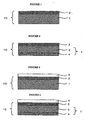
- Fig. 1 is a sectional view showing one embodiment of the adhesive sheet of the present invention.
- the adhesive sheet 10 of the present invention comprises a substrate layer 1 and an adhesive layer 2 laminated on one side of the substrate layer 1.
- the tensile modulus of elasticity in the machine direction (MD-M) and the tensile modulus of elasticity in the transverse direction (TD-M) of the adhesive sheet 10 of the invention at 23°C are in the range of 50 to 2000 MPa, preferably 70 to 1500 MPa, and the ratio of the tensile modulus of elasticity in the machine direction (MD-M) to the tensile modulus of elasticity in the transverse direction (TD-M), that is, (MD-M) / (TD-M), is in the range of 0.5 to 2, preferably 0.7 to 1.5, in order to attain excellent cutting processability.
- the tensile modulus of elasticity is measured according to JIS K 6781.
- the tensile modulus of elasticity of the adhesive sheet 10 is less than 50 MPa, the resulting film may be elongated in the operation of attachment or release thus deteriorating workability so that even if the adhesive sheet is attached correctly, required properties such as accuracy may be hardly achieved. It is not preferable either that the tensile modulus of elasticity is higher than 2000 MPa, because the flexibility thereof to be contour along the shape of an adherend may be reduced.
- the ratio of the tensile modulus of elasticity in the machine direction (MD-M) to the tensile modulus of elasticity in the transverse direction (TD-M), that is, (MD-M)/(TD-M), is less than 0.5 or higher than 2
- the properties in the machine direction may be significantly different from those in the transverse direction, thus failing to attain uniform characteristics in every direction.
- the tear strength in the machine direction (MD-T) and the tear strength in the transverse direction (TD-T) of the adhesive sheet 10 of the invention at 23°C are in the range of 1 to 100 N/mm, preferably 5 to 80 N/mm, and the ratio of the tear strength in the machine direction (MD-T) to the tear strength in the transverse direction (TD-T), that is, [(MD-T)/(TD-T)], is in the range of 0.5 to 2, more effectively 0.7 to 1.5.
- the tear strength is measured according to JIS K 7128 (Elmendorf tear method). When the tear strength is less than 1 N/mm, the adhesive sheet may not be obtained. On the other hand, when the tear strength is higher than 100 N/mm, cutting processability may be made difficult to require special processability.
- MD-T machine direction
- TD-T transverse direction
- the ratio of the tear strength in the machine direction (MD-T) to the tear strength in the transverse direction (TD-T)] is less than 0.5 or higher than 2
- the properties in the machine direction may be made significantly different from those in the transverse direction, thus failing to attain uniform characteristics in every direction.
- the substrate layer 1 preferably comprises an olefin polymer as a major component because the olefin polymer has strength to fix and retain an adherent and flexibility to make the substrate layer contour along the shape of an adherend, is inexpensive and excellent in energy saving, can be selected from materials having various properties, confers functions easily by forming a composite thereof with other materials, hardly brings about a burden on the environment, is substantially free from corrosive ions and metal ions, and easily attains strong adhesion among layers in the case of the adhesive layer formed fromapluralityof layers.
- the major component means a constituent component contained in the highest ratio than other components contained in the substrate layer.
- the olefin polymer further includes low-density polyethylene, very-low-density polyethylene, linear low-density polyethylene, moderate-density polyethylene, high-density polyethylene, and polyethylene copolymers such as copolymers comprising ethylene as main component and various vinyl compounds as minor components selected from C3 to C12 ⁇ -olefins, styrene, vinyl acetate, (meth)acrylic acid, (meth)acrylate and ionomer, which may be random or block copolymers.
- polyethylene copolymers such as copolymers comprising ethylene as main component and various vinyl compounds as minor components selected from C3 to C12 ⁇ -olefins, styrene, vinyl acetate, (meth)acrylic acid, (meth)acrylate and ionomer, which may be random or block copolymers.
- the olefin polymer also includes propylene homopolymers and propylene copolymers comprising propylene as a major component and ethylene or C4 to C12 ⁇ -olefins as minor components, which may be random or block copolymers. Copolymers of C4 or more ⁇ -olefins, such as polybutene and polymethylpentene, can also be mentioned.
- the syndiotactic propylene polymer may be syndiotactic homopropylene or a copolymer comprises propylene, ethylene and if necessary a C4 to C20 olefin, that is, a syndiotactic propylene/ethylene copolymer or a syndiotacticpropylene/ethylene/ ⁇ -olefin copolymer.
- the molar ratio of each of comonomers constituting the copolymer is selected preferably such that propylene is 90 to 99 mol%, ethylene is 0.5 to 9 mol%, and ⁇ -olefin is 0 to 9.5 mol%.
- the ⁇ -olefin used in the syndiotactic propylene/ethylene/ ⁇ -olefin copolymer is used in such a range that the cuttingprocessability, flexibility and mechanical physical properties of the adhesion sheet of the present invention are not deteriorated.
- ⁇ -olefins include 1-butene, 3-methyl-1-butene, 1-hexene, vinylcylohexene, 1-decene, 1-hexadecene, cyclopentene, norbornene etc.
- the syndiotactic propylene copolymer is obtained by copolymerizing propylene with a small amount of comonomer in the presence of a known catalyst giving a poly- ⁇ -olefin excellent in syndiotacticity.
- a repeating unit derived from propylene constituting the syndiotactic propylene polymer used in the present invention is a substantially syndiotactic structure.
- the syndiotacticity thereof viewed from a triad chain of propylene is preferably 0.6 or more, more preferably 0.7 or more.
- the syndiotacticity is in the above range, the rate of crystallization is high, and the resulting polymer is excellent in processability.
- the "substantially syndiotactic structure” means that the syndiotacticity viewed from a triad chain of propylene is 0.6 or more.
- the catalyst used in production of the syndiotactic propylene polymer is preferably a metallocene-based catalyst.
- a catalyst system described by J. A. Ewen et al. in J. Am. Chem. Soc., 110, 6255-6256 (1988) and catalyst systems consisting of crosslinked transition metal compounds having mutually asymmetric ligands and cocatalysts as described in JP-A 2-41303, JP-A 2-41305, JP-A 2-274703, JP-A 2-274704, JP-A 3-179005, JP-A 3-179006 and JP-A 4-69394.
- a catalyst system even using a catalyst having a structure different from that in the above catalyst systems can also be utilized insofar as the resulting propylene homopolymer is a relatively highly tactic polymer having a syndiotactic triad fraction (A. Zambelli et al.: Macromolecules vol 6, 687 (1973), ibid. vol. 8, 925 (1975)) in the above-mentioned range, for example 0.6 or more.
- a polymerization method either a liquid phase polymerization method such as suspension polymerization and solution polymerization or a gaseous phase polymerization method can be used.
- the molecular weight of the syndiotactic propylene polymer in terms of intrinsic viscosity determined in a tetracycline solvent at 135°C, is in the range of preferably 0.1 to 10 dl/g, more preferably 0.5 to 5.0 dl/g.
- the melt flow rate (at a temperature of 230°C with a loading of 21.18 N according to ASTM D-1238) is preferably 0.5 to 70 g/10 min., more preferably 5 to 30 g/10 min.
- the density is preferably 0.81 to 0.96 g/cm 3 , more preferably 0.85 to 0.93 g/cm 3 .
- a resin containing the syndiotactic propylene polymer is used as the component constituting the substrate layer 1, by which the tensile modulus of elasticity and tear strength of the adhesion sheet 10 can be set in a preferable range, uniformity in the machine and transverse directions can be improved, and a cut processed surface can be prevented from generating fibrous burrs .
- the content of the syndiotactic propylene polymer based on the total resin components constituting the substrate layer 1 in the present invention is 10 to 100 wt%, more preferable 30 to 100 wt%.
- the syndiotactic propylene polymer includes, for example, a commercial product available under the registered trade name FINAPLAS from Atofina Petrochemicals, Inc.
- the content of the olefin polymer in the substrate layer 1 is preferably 30 to 100 wt%, more preferably 50 to 100 wt%.
- the ethylene/ ⁇ -olefin copolymer as one example of the olefin polymer improving flexibility and stretchability includes, for example, Tafmer A, Tafmer P etc. (manufactured by Mitsui Chemicals,INC.), the propylene/ ⁇ -olefin coplymer includes, for example, Tafmer XR,Tafmer S etc. (manufactured by Mitusi Chemicals),and the polybutene includes Beaulon (Mitsui Chemicals,INC.).
- a synthetic resin and thermoplastic elastomer besides the olefinic polymer can be added if necessary as a constituent component of the substrate layer 1 in such a range that the performance and qualities of the adhesive sheet 10 are not deteriorated.
- the synthetic resin for improving mechanical properties and heat resistance includes, for example, polyamide, polyester, polyether, polycarbonate and polyurethane
- the thermoplastic elastomer for improving flexibility includes a polyethylene elastomer, polyamide elastomer, polyurethane elastomer and polyester elastomer.
- the substrate layer 1 may contain various additives used generally in a substrate layer in this kind of adhesive sheet.
- various kinds of additives such as fillers, pigments, dyes, UV absorbers, antioxidants, heat stabilizers, lubricants, weatherability stabilizers, plasticizers and crystallization nucleating agents may be contained in such a range that the performance and qualities of the adhesive sheet 10 are not adversely affected
- the thickness of the substrate layer 1 is not particularly limited, and is usually 10 ⁇ m to 1 mm in consideration of cutting processability, mechanical strength, flexibility etc. required depending on the intended use, preferably 25 ⁇ m to 250 ⁇ m in respect of prevention of defects, operativeness in attachment, and price.
- the adhesive layer 2 comprises 30 wt% or more of a mixture of one or more ⁇ -olefin copolymers based on two or more repeating ( ⁇ -olefin units selected from C 2 to C 12 ⁇ -olefins.
- olefin adhesive material examples include, but are not limited to, ⁇ -olefin copolymers described in JP-A 7-233354, JP-A 10-298514, JP-A 11-80233, JP-A 11-43655, JP-A 11-21519, JP-A 11-106716, JP-A 2002-155249 and JP-A 2002-226814.
- the ⁇ -olefin copolymer is used preferably as a major component in the adhesive layer 2 so that the resulting adhesive layer can be well fixed to, and easily released from, an adherend, is substantially free from pollution of an adherend therewith, exhibits stable adhesion in an environment for storage and transport, hardly exerts a burden on the environment, hardly contains corrosive ions and metallic ions, and easily attain strong adhesion to the substrate layer.
- the major component in the adhesive layer is preferably a mixture of one or more ⁇ -olefin copolymers based on two or more repeating ⁇ -olefin units selected from C2 to C12 ⁇ -olefins.
- the C2 to C12 ⁇ -olefins include, for example, ethylene, propylene, 1-butene, 1-pentene, 3-methyl-1-butene, 1-hexene, 4-methyl-1-pentene, 3-methyl-1-pentene, 1-heptene, 1-octene, 1-decene, 1-dodecene etc.
- the total content of ⁇ -olefin copolymers in the adhesive layer 2 is preferably 30 wt% or more, particularly preferably 50 wt% or more.
- an ethylene/other ⁇ -olefin cooligomer or a halogen element-free thermoplastic elastomer besides the ⁇ -olefin copolymer, can be added if necessary.
- the ethylene/other ⁇ -olefin cooligomer or the halogen element-free thermoplastic elastomer is added preferably to the adhesive layer 2 so that the glass transition temperature is lowered, the initial adhesion can be regulated in a suitable range, and the viscosity can be regulated in a suitable range.
- an oxygen- or nitrogen-containing polar group or a group having an unsaturated bond is introduced to a suitable degree into a part of the ⁇ -olefin copolymer and thermoplastic elastomer, because the adhesive layer 2 after attachment can be prevented from undergoing a change in adhesion with time (due to heating, pressurization, humidity, UV rays etc.) and the processing conditions and adhesion thereof to an adherend can be optimized.
- the ethylene/other ⁇ -olefin cooligomer comprises a low-molecular ethylene/other ⁇ -olefin copolymer usually having a number-average molecular weight preferably in the range of 100 to 10000, more preferably in the range of 200 to 5000.
- the thermoplastic elastomer includes, for example, styrene/butadiene block copolymer (SBR), styrene/isoprene/styrene block copolymer (SIS), styrene/butadiene/styrene block copolymer (SBS), styrene/ethylene/butylene/styrene block copolymer (SEBS), styrene/ethylene/propylene/styrene block copolymer (SEPS), hydrogenated styrene/butadiene block copolymer (HSBR), styrene/ethylene/butylene/olefin (crystalline) block copolymer (SEBC), olefin (crystalline)/ethylene/butylene/olefin (crystalline) block copolymer (CEBC) etc.
- SBR styrene/butadiene block copolymer
- SIS styrene/
- Examples of SIS include a product available under the registered trade name JSR SIS from JSR CORPORATION and a product available under the registered trade name Claytone D from Shell Chemicals Japan Ltd.
- Examples of SEPS include a product available under the registered trade name Septone from Kuraray co., Ltd.
- Examples of HSBR, SEBS, SEBC and CEBC include products available under the registered trade name Dynaron from JSR CORPORATION.
- the adhesive layer 2 may contain various minor components in addition to the ⁇ -olefin copolymer, the ethylene/other ⁇ -olefin cooligomer and the thermoplastic elastomer in such a range that the object of the present invention is not hindered.
- a plasticizer such as liquid butyl rubber, a tackifier such as polyterpene, etc. may be contained.
- functional groups for conferring adhesiveness and groups having unsaturated bonds are selected and the amount of the minor components blended is limited desirably to the minimum to prevent the adhesive layer 2 after attachment from undergoing a change in adhesion with time (due to heating, pressurization, humidity, UV rays etc.).
- the adhesive layer in the present invention may contain various additives incorporated generally into this kind of adhesive material.
- various kinds of additives such as pigments, dyes, UV absorbers, antioxidants, heat stabilizers, weatherability stabilizers, etc. may be contained.
- the thickness of the adhesive layer 2 is not particularly limited, and is usually 1 ⁇ m to 200 ⁇ m, preferably 5 to 50 ⁇ m, in consideration of properties required depending on the intended use, such as cutting processability, tackiness, and adhesion to an uneven surface of an adherend.
- the thickness of the adhesive sheet 10 as a whole is usually 10 ⁇ m to 1 mm, preferably 30 to 300 ⁇ m, in respect of prevention of defects, operativeness in attachment, and price.
- the tackiness of the adhesive sheet 10 to various kinds of adherend used is not particularly limited, and is usually 0.05 to 50 N/25 mm, preferably 0.1 to 20 N/25 mm.
- the adhesive layer 2 may consists of a known switching adhesive for lowering the tackiness to a lower level or even to zero.
- Fig. 2 is a sectional view showing another embodiment of the adhesive sheet of the present invention.
- the adhesive sheet 10 of the present invention comprises a substrate layer 1 consisting of 2 layers (i.e. intermediate layer 3 and external layer 4) and an adhesive layer 2 laminated on one side of the intermediate layer 3.
- the intermediate layer 3 adjacent to the adhesive layer 2 preferably comprises an olefin polymer containing a syndiotactic propylene polymer, and the content thereof is usually 10 to 100 wt%, preferably 30 to 100 wt%.
- the olefin polymer includes those described above.
- the major component in the external layer 4 is preferably low-density polyethylene, very-low-density polyethylene, linearlow-density polyethylene,moderate-density polyethylene, high-density polyethylene, and polyethylene copolymers such as copolymers comprising ethylene and various vinyl compounds such as C3 to C12 ⁇ -olefins ,styrene, vinyl acetate, (meth) acrylic acid, (meth)acrylate and ionomer.
- polyethylene copolymers such as copolymers comprising ethylene and various vinyl compounds such as C3 to C12 ⁇ -olefins ,styrene, vinyl acetate, (meth) acrylic acid, (meth)acrylate and ionomer.
- a release agent such as a reaction product of a small amount of polyvinyl alcohol or an ethylene/vinyl alcohol copolymer and long-chain alkyl isocyanate is preferably compounded in an amount of 0.1 to 5 wt%, and an adhesive sheet having an unwinding force of not higher than 5 N/25 mm can be obtained without using a release sheet.
- the thickness of the intermediate layer 3 and external layer 4 is not particularly limited, and the thickness of the intermediate layer 3 is preferably 10 ⁇ m to 0.8 mm, particularly preferably 20 to 200 ⁇ m, and the thickness of the external layer 4 is preferable 3 to 200 ⁇ m, particularly preferably 5 to 50 ⁇ m.
- the thickness of the substrate layer 1 having the adhesive layer 2 laminated on one side of the substrate layer 1 consisting of a single layer is preferably at least 30% relative to the total thickness of the adhesive sheet 10, or when the adhesive layer 2 is laminated on one side of the substrate layer 1 consisting of a plurality of layers, the thickness of the intermediate layer 3 adjacent to the adhesive layer 2 is preferably at least 30% relative to the total thickness of the adhesive sheet 10.
- Fig. 3 is a sectional view showing another embodiment of the adhesive sheet of the present invention.
- the adhesive sheet 10 in the present invention comprises a substrate layer 1, an adhesive layer 2 laminated on the surface of the substrate layer 1, and a release sheet 5 arranged in the side of the adhesive layer 2.
- Fig. 4 is a sectional view showing another embodiment of the adhesive sheet of the present invention.
- the adhesive sheet 10 in the present invention comprises a substrate layer 1 consisting of 2 layers (i.e. an intermediate layer 3 and an external layer 4) and an adhesive layer 2 laminated on the surface of the intermediate layer 3, and a release sheet 5 is arranged in the side of the adhesive layer 2
- the adhesive sheet 10 of the present invention is preferably a sheet having the release sheet 5 laminated in the side of the adhesive layer, in order to facilitate unwinding of the adhesive sheet, to improve the surface smoothness of the adhesive layer and to improve punching processability.
- a release sheet is usually used to protect the adhesive layer.
- the release sheet 5 is formed from various known constituent components and is not particularly limited, but is preferably synthetic resin or coated paper not generating toxic gas such as halogen compound upon combustion treatment.
- coated paper having synthetic resin such as polyethylene applied onto the surface of polyester film or paper is preferable from the viewpoint of rigidity for preventing deformation to punch the adhesive sheet 10 with high accuracy, thickness and flexibility not problematic in rolling, and reduction in the amount of waste material.
- the synthetic resin used in the release sheet 5 may contain various fillers, pigments, UVabsorbers, antioxidants, heat stabilizers, lubricants etc. in such an extent that the adhesive sheet is not adversely affected.
- a release layer may be formed on the surface of the release sheet 5 adjacent to the adhesive sheet 10.
- various release agents used generally in a release layer in this kind of release sheet 5 are used.
- long-chain alkyl release agents such as a long-chain alkyl acrylate copolymer, a long-chain alkyl vinyl ester copolymer and a long-chain alkyl vinyl ether copolymer, silicone-based release agents and fluorine-based release agents can be mentioned.
- the unevenness of the release sheet is transferred onto the surface of the adhesive layer, and thus the surface roughness Ra is preferably in the range of 1 to 0.01 ⁇ m.
- the release sheet 5 is pre ferably as thin as possible so as to be unproblematic in rolling and to reduce the amount of waste material, and the thickness is preferably 5 to 300 ⁇ m, more preferably 15 to 150 ⁇ m.
- a release sheet consisting of polyethylene terephthalate (PET) is for example a commercial product available under the registered trade name Tohcello Separator SP from Tohcello Co., Ltd.
- a release sheet consisting of coated paper is for example a commercial product available under the trade name Separate from Oji Paper Co., Ltd.
- a method of laminating the adhesive layer on the surface of the substrate layer 1 is not particularly limited, and the adhesive sheet can be produced for example by a method wherein a substrate sheet (substrate layer) made of an olefin polymer previously formed by a known inflation method, T-die method, calender method or the like is subjected to surface treatment such as corona treatment, and then an adhesive material is applied thereon and dried, a method that involves applying and drying an adhesive material on a release sheet and then contact-bonding the release sheet to a previously formed substrate sheet (substrate layer) made of an olefin polymer, a method of co-extrusion of an adhesive layer and a substrate layer, or a method of laminating an adhesive layer by melt-extrusion onto a previously formed substrate layer.
- the co-extrusion method is a method of producing a laminate sheet having a multi-layer structure of predetermined thickness by melt-heating the respective materials constituting the substrate layer and the adhesive layer and subsequent extrusion-molding thereof, and is preferable in respect of high efficiency and energy saving to produce the laminate sheet inexpensively.
- an adhesive sheet having one or more substrate layers and an adhesive layer can be simultaneously formed.
- the co-extrusion method using the multi-layer T-die includes, for example, a method that involves combining melts of the layers in a layered form, then feeding them to a flat die, and bonding them in the die (feed block method), a method that involves delivering melts of the layers into manifolds respectively in a flat die, bonding the layers in a layered form in a common place (generally before an inlet of a die slip), then feeding them to the flat die and bonding them in the die (multi-manifold method), and a method comprising the feed block method combined with the multi-manifold method.
- feed block method a method that involves combining melts of the layers in a layered form, then feeding them to a flat die, and bonding them in the die
- multi-manifold method multi-manifold method
- the method of laminating the thus obtained adhesive sheet 10 on the release sheet 5 is not particularly limited, and for example a usual sheet laminating device can be used.
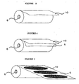
- the adhesive sheet 10 of the present invention can be wound around a core material 6 and stored in a rolled state, and can be used by unwinding a necessary amount of the adhesive sheet.
- the release sheet 5 can stuck to the adhesive layer in the adhesive sheet 10 of the present invention, then wound around a core material 6 and stored in a rolled state, and can be used by unwinding a necessary amount of the adhesive sheet and then releasing the release sheet 5.
- the adhesive sheet 10 of the present invention can be punched off in the most suitable shape (for example, circular) for intended use and maintained on the release sheet 5, can be wound around a core material 6 and stored in a rolled state, and can be used by unwinding a necessary amount of the adhesive sheet and releasing the release sheet 5.
- the shape is not particularly limited, and may be circular, square or rectangular, and for example, the adhesive sheet 10 may be left partially on the release sheet 5 and punched off inanecessary shape.
- the adhesive sheet 10 according to the present invention is used in a wide variety of conventionally known applications. Applications of the adhesive sheet are not particularly limited, but are preferably applications to surface protection involving cutting processing, treatment with a chemical solution, and dicing. Hereinafter, these applications are described.
- the adhesive sheet 10 of the present invention while being stuck to the surface of an adherend can be used preferably in surface protection involving cutting processing in a desired shape.
- a method of using a rotating blade made of metal or diamond, a laser, water jetting is generally used.
- the adhesive sheet 10 of the present invention has the specific tensile modulus of elasticity and tear strength, can thus achieve processing with good accuracy without generating defects on a cut surface, can prevent generation of fibrous burrs or adhesion of cutting dust, and can thus be used preferably as an adhesive sheet for surface protection that involves cutting electronic circuit materials, semiconductor materials and optical materials demanding strict requirements for performance and qualities.
- the adhesive sheet 10 is punched off in a shape in accordance with the shape of a print substrate and a pattern of a circuit, then the adhesive sheet 10 is stuck to the print substrate if necessary by thermal contact-bonding thereby permitting the adhesive sheet to adhere completely to the print substrate. While regions for terminals to be plated, regions for terminals not to be plated and regions such as circuit are protected with high accuracy, the print substrate is dipped in a plating solution heated at about 40°C to about 95°C, then washed with water and dried, followed by removing the adhesive sheet. The adhesive sheet after use is disposed of by combustion or the like.
- the print substrate comprises, for example, a circuit consisting of a conductive metal such as copper or aluminum formed on a plate-shaped substrate made of an insulator such as glass, ceramics or plastics.
- the thickness of the print substrate is usually several tens ⁇ m to several mm, and the area is usually several cm 2 to thousands cm 2 , and the shape is circular, square, rectangular etc.
- the thickness of the adhesive sheet used is also cut and processed in various forms.
- the electroless plating is a method of utilizing a chemically reducing action wherein a material to be plated is dipped in a metallic salt solution containing a soluble reducing agent, a pH regulator, and a stabilizer for the plating solution to form a metallic coating on the material.
- the print substrate is plated with various metals such as copper, nickel, gold, palladium and tin or an alloy by electric plating or electroless plating.
- the electroless plating is used mainly for print substrate required to be thin and fine, particularly for flexible print substrate, because wiring on a material to be plated is not necessary and a plating metal film is excellent in uniformity.
- the electroless plating includes electroless nickel plating, electroless copper plating, electroless cobalt plating, electroless tin plating, electroless palladium plating, electroless silver plating and electroless gold plating, and for plating the print substrate and flexible print substrate, nickel plating, gold plating, copper plating, palladium plating and tin plating are suitably used depending on various requirements such as electrical conductivity, wear resistance, rust prevention, hardness, dimensional accuracy, weatherability, and chemical resistance.
- the temperature of a nickel plating solution is for example about 60 to about 95°C, and the pH is 3 (acidic) to 11 (alkaline).
- the temperature of a gold plating solution is about 70°C to about 80°C, and the pH is for examples 12 to 14.
- the temperature of a copper plating solution is 40°C to 60°C, and the pH is for example 12 to 13.
- etching treatment with sulfuric acid etc. or various surface activation treatments may be suitably carried out to remove an oxide film such as copper oxide.
- a substrate having a circuit formed with cupper foil in a thickness of 18 ⁇ m or less on a polyimide substrate sheet of 13 ⁇ m in thickness is generally used.
- the adhesive sheet used in a step of processing such flexible print substrate having a considerably fine and thinned circuit demands stricter requirements.
- the adhesive sheet demands stability to chemical treatment solutions heated at 40°C to 95°C showing acidity to alkalinity, such as plating solution and etching solution, and higher punching processability for high accuracy required of flexible print substrate.
- the adhesive sheet of the present invention is free of fibrous burrs upon punching processing and excellent in processing accuracy, and also superior in stability to chemical treatment solutions such as plating solution and etching solution, and therefore, the substrate after release of the adhesive sheet is free of adhering contaminants derived from the adhesive sheet. Accordingly, the adhesive sheet 10 of the present invention can be used without any problem in qualities even if the print substrate or flexible print substrate is not washed with a Freon organic solvent, thus reducing a burden on the environment.
- the adhesive sheet 10 of the present invention is preferable not only in the plating treatment but also as a protective sheet for protecting a surface not treated with a chemical in the treatment of various kinds of adherend with an acidic or alkaline chemical in a process for producing electronic circuit materials or semiconductor materials.
- dicing involves steps wherein the adhesive sheet 10 of the present invention is contact-bonded at room temperature or under heating to a wafer as adherend, then the wafer is cut (diced) into chips, washed and dried, the adhesive sheet is stretched, and thereafter the chips are picked up and released from the adhesive sheet.
- the adhesive sheet 10 of the present invention can be fixed closely to a wafer, to maintain the wafer, and thus the chips are not released in the above steps.
- the wafer may be any generally solid wafer, and includes semiconductor materials for example element semiconductors such as silicon, germanium, selenium, tellurium etc.; binary compound semiconductors such as GaAs, GaP, InSb etc.; ternary compound semiconductors such as AlGaAs etc.; quaternary compound semiconductors such as AlGaInAs etc.; and metal oxide semiconductors such as SnO 2 , ZnO, TiO 2 , Y 2 O 5 etc.
- the electronic circuit material is for example a material wherein an electronic circuit formed on a wafer consisting of the above semiconductor material is covered with a rigid plastic material, and the optical material includes a material consisting of glass or ceramics.
- the thickness of the wafer is usually several tens ⁇ m to several mm, and the area of the wafer is usually several tens cm 2 to thousands cm 2 , and the shape is circle, square, rectangle, etc.
- the substrate layer 1 in the present invention comprises an olefin polymer excellent not only in stretchability but also in cutting processability to prevent cutting dust generated upon cutting from growing and washing the dust away in fine form with washing water, thus being free of the cutting dust and being sufficiently stretchable after dicing.
- the adhesive sheet 10 of the present invention can also prevent cutting dust from growing under dicing conditions where cutting dust is easily generated, and therefore the movement of a rotating knife of diamond is not disturbed by cutting dust, thus reducing chipping.
- the adhesive sheet 10 of the present invention can reduce the wear of a metal blade or diamond blade used in punching processing and dicing processing.
- the adhesive sheet 10 of the present invention can achieve accurate processing without chipping from a cut processed surface and can prevent generation of fibrous burrs and adhesion of cutting dust, and can thus be applied as an adhesive sheet for cutting processing with a laser and water jet.
- test specimens in the machine direction and transverse direction were prepared from an adhesive sheet and examined in a tensile test in an environment at a temperature of 23°C and a relative humidity of 50%. From tensile stress measured in distortion in two points in a stress-distortion curve obtained in this tensile test, the tensile modulus of elasticity was calculated.
- the tensile modulus of elasticity (23°C) shown in the Examples below is the average of at least 5 measurements, and the unit is MPa.
- test specimens in the machine direction and transverse. direction were prepared from an adhesive sheet and examined in a tear strength test in an environment at a temperature of 23°C and a relative humidity of 50%.
- the tear strength (23°C) shown in the Examples below is the average of at least 5 measurements, and the unit is N/mm.
- an adhesion test was carried out in an environment at a temperature of 23°C and a relative humidity of 50%. Under pressurization with 2 kg rubber roll, an adhesive sheet was stuck to an SUS-BA plate as test plate, and then placed for 30 minutes in a predetermined environment at a temperature of 23°C and a relative humidity of 50%, and while the adhesive sheet was released at a direction of 180° at a rate of 300 mm/min. from the test plate, its adhesion was measured.
- the adhesion (23°C) shown in the Examples below is the average of at least 2 measurements, and the unit is N/25 mm.
- each layer constituting the adhesive sheet 10 As the material of each layer constituting the adhesive sheet 10, the following materials were used. That is, 30 parts by weight of syndiotactic propylene polymer (s-PP; FINAPLAS TM 1571; density 0. 87 g/cm 3 ; Atofina Petrochemicals, Inc.), 10 parts by weight of high-density polyethylene (HDPE; density 0.
- s-PP syndiotactic propylene polymer
- HDPE high-density polyethylene
- LDPE low-density polyethylene
- PB(4-MP) propylene/1-butene/4-methyl-1-pentene copolymer
- EP-A an ethylene/propylene copolymer
- EP-A 81 mol% ethylene component, 19 mol% propylene; density 0.87 g/cm 3
- SIS styrene/isoprene/styrene block copolymer
- LEO low-density polyethylene
- the material of each layer was melted in an extruder equipped with a full-flighted screw. Molding conditions (melting temperature) were 220°C for the adhesive layer and 230°C for the substrate layer 1, and molten resins of the 2 layers were laminated in a multi-layer die (co-extrusion temperature: 230°C).
- the extruded adhesive sheet 10 was cooled, slit and wound around a core material 6.
- the adhesive sheet 10 thus obtained was a laminate of the single substrate layer 1 and the adhesive layer 2, and the thickness of each layer was 8 ⁇ m for the adhesive layer 2 and 42 ⁇ m for the substrate layer 1, and the total thickness was 50 ⁇ m.
- MD-T machine direction
- TD-T transverse direction
- the adhesive sheet as test specimen was closely stuck to an acrylic plate of 300 mmx300 mmx1 mm thickness and placed for 30 minutes in a drying oven set at a temperature of 80°C, and subjected to cutting processing with a rotating blade.
- Evaluation criteria were as follows: the adhesive sheet not generating fibrous burrs on a cut processed surface without contamination with adhering cutting dust was regarded as passing the examination (designated O), and the adhesive sheet generating fibrous burrs on a cut processed surface or undergoing contamination with adhering cutting dust was regarded as not passing the examination (designated ⁇ ). The presence or absence of fibrous burrs or contaminants such as residual glue was judged by observation under an optical microscope (x200).
- the resulting adhesive sheet 10 is excellent in application to surface protection involving cutting processing.
- Table 1 shows the layer constitution of the adhesive sheet 10, the component constituting each layer and the weight ratio thereof, and the thickness of each layer.
- the tensile modulus of elasticity (A), tear strength (B) and adhesion (C) of the resulting adhesive sheet 10 were examined, and the results are shown in Table 2.
- the results of evaluation of the surface protection suitability (D) of the resulting adhesive sheet 10 are shown in Table 3.
- each layer constituting the adhesive sheet 10 As the material of each layer constituting the adhesive sheet 10, the following materials were used. That is, 60 parts by weight of the same s-PP as in Example 1, 30 parts by weight of a propylene/ethylene/1-butene random copolymer (r-PP: 5 mol% ethylene component, 5 mol% 1-butene component) and 10 parts by weight of the same HDPE as inExample 1 were used as the component of the intermediate layer 3 in the substrate layer 1, 80 parts by weight of the same HDPE as in Example 1 and 20 parts by weight of the same LDPE as in Example 1 were used as the component of the external layer 4 in the substrate layer 1, and 60 parts by weight of the same PB(4-MP) as in Example 1, 5 parts by weight of the same EP-A as in Example 1, 10 parts by weight of a propylene polymer (h-PP; density 0.91 g/cm 3 ), 10 parts by weight of a styrene/ethylene/butylene/styrene block copolymer
- the material of each layer was melted in an extruder equipped with a full-flighted screw. Molding conditions (melting temperature) were 230°C for the adhesive layer 2, 230°C for the intermediate layer 3 and 220°C for the external layer 4, andmolten resins of the 3 layers were laminated in amulti-layer die (co-extrusion temperature: 230°C).
- the extruded adhesive sheet 10 was cooled, slit and wound around a core material 6.
- the adhesive sheet 10 thus obtained was a laminate of the 2-layer substrate layer 1 and the adhesive layer 2, and the thickness of each layer was 8 ⁇ m for the adhesive layer 2, 34 ⁇ m for the intermediate layer 3, and 8 ⁇ m for the external layer 4, and the total thickness was 50 ⁇ m.
- Table 1 shows the layer constitution of the adhesive sheet 10, the component constituting each layer and the weight ratio thereof, and the thickness of each layer.
- the tensile modulus of elasticity (A), tear strength (B) and adhesion (C) of the resulting adhesive sheet 10 were examined, and the results are shown in Table 2.
- the results of evaluation of the surface protection suitability (D) of the resulting adhesive sheet 10 are shown in Table 3.
- each layer constituting the adhesive sheet 10 As the material of each layer constituting the adhesive sheet 10, the following materials were used. That is, 90 parts by weight of the same s-PP as in Example 1 and 10 parts by weight of the same HDPE as in Example 1 were used as the component of the intermediate layer 3 in the substrate layer 1, the same component in the same ratio as in Example 2 was used as the component of the external layer 4 in the substrate layer 1, and the same component in the same ratio as in Example 2 was used as the component of the adhesive layer 2.
- the material of each layer was melted in an extruder equipped with a full-flighted screw. Molding conditions (melting temperature) were 230°C for the adhesive layer 2, 230°C for the intermediate layer 3 and 220°C for the external layer 4, andmolten resins of the 3 layers were laminated in amulti-layer die (co-extrusion temperature: 230°C).
- the extruded adhesive sheet 10 was cooled, slit and wound around a core material 6.
- the adhesive sheet 10 thus obtained was a laminate of the 2-layer substrate layer 1 and the adhesive layer 2, and the thickness of each layer was 8 ⁇ m for the adhesive layer 2, 24 ⁇ m for the intermediate layer 3, and 8 ⁇ m for the external layer 4, and the total thickness was 40 ⁇ m.
- Table 1 shows the layer constitution of the adhesive sheet 10, the component constituting each layer and the weight ratio thereof, and the thickness of each layer.
- the tensile modulus of elasticity (A), tear strength (B) and adhesion (C) of the resulting adhesive sheet 10 were examined, and the results are shown in Table 2.
- the results of evaluation of the surface protection suitability (D) of the resulting adhesive sheet 10 are shown in Table 3.
- Adhesive sheet 10 ⁇ present Adhesive layer 2
- Example 1 Tensile modulus of elasticity (B) Tear strength (C) Adhesion (N/25 mm) MD-M (MPa) TD-M (MPa) MD-M/ TD-M (-) MD-T (N/mm) TD-T (N/mm) MD-T/ TD-T (-)
- Example 1 240 170 1.41 30 58 0.52 1.2
- Example 3 450 440 1.02 6.5 6.2 1.05 1.5' Table 3.
- D Surface protection suitability Example 1 ⁇ Example 2 ⁇
- Example 3 Example 3 ⁇
- each layer constituting the adhesive sheet 10 As the material of each layer constituting the adhesive sheet 10, the following materials were used. That is, 80 parts by weight of the same s-PP as in Example 1 and 20 parts by weight of the same h-PP as in Example 2 were used as the component of the substrate layer 1, and 70 parts by weight of the same PB(4-MP) as in Example 1, 5 parts by weight of the same EP-A as in Example 1, 10 parts by weight of the same h-PP as in Example 2, and 15 parts by weight of an olefin (crystalline)/ethylene/butylene/olefin (crystalline) block copolymer (DYNARON TM 6200P manufactured by JSR CORPORATION) were used as the component of the adhesive layer 2 in Example 1.
- olefin (crystalline)/ethylene/butylene/olefin (crystalline) block copolymer DYNARON TM 6200P manufactured by JSR CORPORATION
- the extruded adhesive sheet 10 was cooled, provided with Tohcello Separator TM SP T18 (PET-SP, thickness 50 ⁇ m; manufactured by Tohcello) as a release sheet 5 on the adhesive layer, and then slit and wound.
- the adhesive sheet 10 thus obtained was a laminate of the 2-layer substrate layer 1 and the adhesive layer 2, and the thickness of each layer was 20 ⁇ m for the adhesive layer 2 and 100 ⁇ m for the substrate layer 1, and the total thickness was 120 ⁇ m.
- a silicon wafer of ⁇ 100 mm was used as wafer 21 for chemical suitability test, on which pH testing papers 20 were placed, and as shown in a sectional view of wafer in Fig.
- the evaluation criteria were as follows: When the pH testing paper maintained the color of pH 7 and simultaneously the wafer 21 was not contaminated with residual glue, the adhesive sheet was regarded as passing the test (designated O); when the pH testing paper maintained the color of pH 7 and simultaneously contaminants occurred around only the adhesive sheet 10 stuck to the wafer 21 for chemical suitability test, the adhesive sheet was regarded unsuitable (designated ⁇ ) ; and when the pH testing paper was changed, or when contaminants such as residual glue occurred on the wafer 21 for chemical suitability test, the adhesive sheet was regarded as not passing the test (designated x). Whether contaminants such as residual glue occurred or not was judged by observation under an optical microscope (x200). When judged to be unsuitable, contaminants occurring around the adhesive sheet 10 couldbe removed by washing with water; when the contaminants could not be removed, the adhesive sheet was evaluated as not passing the test.
- the resulting adhesive sheet 10 did not permit the pH testing paper to be changed with any chemical solutions such as hydrogen fluoride/nitric acid/acetic acid, aqua regia and ammonia water, and was free of contaminants and superior in application to acidic to alkali chemical treatment.
- Table 4 shows the layer constitution of the adhesive sheet 10, the component constituting each layer and the weight ratio thereof, and the thickness of each layer.
- the tensile modulus of elasticity (A), tear strength (B) and adhesion (C) of the resulting adhesive sheet 10 were examined, and the results are shown in Table 5.
- the results of evaluation of (E) chemical treatment suitability of the resulting adhesive sheet 10 are shown in Table 6.
- each layer constituting the adhesive sheet 10 As the material of each layer constituting the adhesive sheet 10, the following materials were used. That is, 40 parts by weight of the same s-PP as in Example 1, 40 parts by weight of the same h-PP as in Example 2, 10 parts by weight of the same HDPE as in Example 1, and 10 parts by weight of PP-based blue dye (b-dye; 5B-E5133MB Blue manufactured by Nippon Pigment Co., Ltd.) were used as the component of the intermediate layer 3 in the substrate layer 1, 100 parts by weight of the same HDPE as in Example 1 were used as the component of the external layer 4 in the substrate layer 1, and 70 parts by weight of the same PB(4-MP) as in Example 1, 6 parts by weight of the same CEBC as in Example 4, 6 parts by weight of the same SIS as in Example 1, 15 parts by weight of a styrene/ethylene/butylene/styrene. (crystalline) block copolymer (SEBS-A; DYNARON TM 9901P manufactured by JSR CO
- the material of each layer was melted in an extruder equipped with a full-flighted screw. Molding conditions (melting temperature) were 220°C for the adhesive layer 2, 230°C for the intermediate layer 3, and 220°C for the external layer 4, andmolten resins of the 3 layers were laminated in amulti-layer die (co-extrusion temperature: 230°C).
- the extruded adhesive sheet 10 was cooled, then provided on the adhesive layer with the same PET-SP (thickness 50 ⁇ m) as release sheet 5 as in Example 4, slit and wound on the core material 6.
- the adhesive sheet 10 thus obtained was a laminate of the 2-layer substrate layer 1 and the adhesive layer 2, and the release sheet 5 was arranged in the side of the adhesive layer, and the thickness of each layer was 20 ⁇ m for the adhesive layer 2, 70 ⁇ m for the intermediate layer 3, and 10 ⁇ m for the external layer 4, and the total thickness was 100 ⁇ m.
- Table 4 shows the layer constitution of the adhesive sheet 10, the component constituting each layer and the weight ratio thereof, and the thickness of each layer.
- the tensile modulus of elasticity (A), tear strength (B) and adhesion (C) of the resulting adhesive sheet 10 were examined, and the results are shown in Table 5.
- the results of evaluation of the chemical treatment suitability (E) of the resulting adhesive sheet 10 are shown in Table 6.
- each layer constituting the adhesive sheet 10 As the material of each layer constituting the adhesive sheet 10, the following materials were used. That is, 40 parts by weight of the same s-PP as in Example 1, 40 parts by weight of the same r-PP as in Example 2, 10 parts by weight of the same HDPE as in Example 1, and 10 parts by weight of the same b-dye as in Example 5 were used as the component of the intermediate layer 3 in the substrate layer 1, 100 parts by weight of the same HDPE as in Example 1 were used as the component of the external layer 4 in the substrate layer 1, and the same component in the same ratio as in the adhesive layer 2 in Example 5 was used as the component of the adhesive layer 2.
- the material of each layer was melted in an extruder equipped with a full-flighted screw. Molding conditions (melting temperature) were 220°C for the adhesive layer 2, 230°C for the intermediate layer 3, and 220°C for the external layer 4, and molten resins of the 3 layers were laminated in amulti-layer die (co-extrusion temperature: 230°C).
- the extruded adhesive sheet 10 was cooled, then provided on the adhesive layer with the same PET-SP (thickness 50 ⁇ m) as release sheet 5 as in Example 4, slit and wound on the core material 6.
- the adhesive sheet 10 thus obtained was a laminate of then 2-layer substrate layer 1 and the adhesive layer 2, and the release sheet 5 was arranged in the side of the adhesive layer, and the thickness of each layer was 20 ⁇ m for the adhesive layer 2, 70 ⁇ m for the intermediate layer 3, and 10 ⁇ m for the external layer 4, and the total thickness was 100 ⁇ m.
- Table 4 shows the layer constitution of the adhesive sheet 10, the component constituting each layer and the weight ratio thereof, and the thickness of each layer.
- the tensile modulus of elasticity (A), tear strength (B) and adhesion (C) of the resulting adhesive sheet 10 were examined, and the results are shown in Table 5.
- the results of evaluation of (E) chemical treatment suitability of the resulting adhesive sheet 10 are shown in Table 6.
- each layer constituting the adhesive sheet 10 As the material of each layer constituting the adhesive sheet 10, the following materials were used. That is, 70 parts by weight of the same h-PP as in Example 2, 20 parts by weight of the same HDPE as in Example 1, and 10 parts by weight of the same b-dye as in Example 5 were used as the component of the intermediate layer 3 in the substrate layer 1, 100 parts by weight of the same HDPE as in Example 1 was used as the component of the external layer 4 in the substrate layer 1, and the same component in the same ratio as in the adhesive layer 2 in Example 5 was used as the adhesive layer 2.
- the material of each layer was melted in an extruder equipped with a full-flighted screw. Molding conditions (melting temperature) were 220°C for the adhesive layer 2, 230°C for the intermediate layer 3, and 220°C for the external layer 4, andmolten resin of the 3 layers were laminated in a multi-layer die (co-extrusion temperature: 230°C).
- the extruded adhesive sheet 10 was cooled, then provided on the adhesive layer with the same PET-SP (thickness 50 ⁇ m) as release sheet 5 as in Example 4, slit and wound on the core material 6.
- the adhesive sheet 10 thus obtained was a laminate of the 2-layer substrate layer 1 and the adhesive layer 2, and the release sheet 5 was arranged in the side of the adhesive layer, and the thickness of each layer was 20 ⁇ m for the adhesive layer 2, 70 ⁇ m for the intermediate layer 3, and 10 ⁇ m for the external layer 4, and the total thickness was 100 ⁇ m.
- Table 4 shows the layer constitution of the adhesive sheet 10, the component constituting each layer and the weight ratio thereof, and the thickness of each layer.
- the tensile modulus of elasticity (A), tear strength (B) and adhesion (C) of the resulting adhesive sheet 10 were examined, and the results are shown in Table 5.
- the results of evaluation of the chemical treatment suitability (E) of the resulting adhesive sheet 10 are shown in Table 6.
- the ratio of the tensile modulus of elasticity in the machine direction to the tensile modulus of elasticity in the transverse direction [(MD-M)/(TD-M)] is higher than 2, and the ratio of the tear strength in the machine direction to the tear strength in the transverse direction [(MD-T)/(TD-T)] is less than 0.5, and in the evaluation of the chemical treatment suitability (E), the chemical permeated through burrs generated around the adhesive sheet upon punching, to discolor the pH testing paper, and the adhesive sheet was evaluated as not passing the test (x) .
- Table 4 Table 4.
- Adhesive sheet 5 Adhesive sheet 10 ⁇ : present Adhesive layer 2 Substrate layer 1 -: absent Constituent Constitutional component of each Type component: weight layer: weight ratio Thickness t ( ⁇ m) ratio Thickness t of each layer ( ⁇ m) Thickness t ( ⁇ m) Intermediate layer 3 External layer 4 ⁇ PB(4MP) 70 s-PP 80 PET-SP EP-A 5 h-PP 20
- Example 6 SEBS-A 15 b-dye 10 L
- Example 4 560 570 1.04 8 9 0.89 2.1
- Example 6 620 550 1.13 14 20 0.70 4.2 Comparative Example 1 1360 610 2.19 12 25 0.48 4.2 Table 6.
- each layer constituting the adhesive sheet 10 As the material of each layer constituting the adhesive sheet 10, the following materials were used. That is, 60 parts by weight of the same s-PP as in Example 1, 32 parts by weight of the same h-PP as in Example 2, 2 parts by weight of the same HDPE as in Example 1 and 6 parts by weight of the same b-dye as in Example 5 were used as the component of the substrate layer 1, and 62 parts by weight of the same PB(4-MP) as in Example 1, 3 parts by weight of the same h-PP as in Example 2, 10 parts by weight of the same CEBC as in Example 4, parts by weight of the same SIS as in Example 1 and 3 parts by weight of the same LEO as in Example 1 were used as the component of the adhesive layer 2.
- the material of each layer was melted in an extruder equipped with a full-flighted screw. Molding conditions (melting temperature) were 220°C for the adhesive layer 2 and 230°C for the substrate layer 1, and molten resins of the 2 layers were laminated in a multi-layer die (co-extrusion temperature: 230°C).
- the extruded adhesive sheet 10 was cooled, then provided with Separator 64GPA(P) White (GP-SP; thickness 95 ⁇ m, a coated sheet having glassine paper as a core material, manufactured by Oji Paper) as release sheet 5 on the adhesive layer, then slit and wound.
- the adhesive sheet 10 thus obtained was a laminate of the 2-layer substrate layer 1 and the adhesive layer 2, and the thickness of each layer was 15 ⁇ m for the adhesive layer 2 and 60 ⁇ m for the substrate layer 1, and the total thickness was 75 ⁇ m.
- the plating suitability in the present invention was evaluated on the basis of observation results in (1) plating resistance and (2) plating operativeness after plating on flexible print substrate under the following test conditions.
- a flexible print substrate (copper wire width 25 ⁇ m; interval 25 ⁇ m) having a circuit consisting of copper foil formed on a polyimide substrate, which was prepared by subjecting Neoflex manufactured by Mitsui Chemicals,INC. (NEX-131R (13H); polyimide substrate thickness, 13 ⁇ m; copper foil, 18 ⁇ m) to etching treatment with an aqueous ferric chloride solution, was used.
- a plating test substrate 10 (40 mm ⁇ 100 mm) as a test specimen having a punched opening (5 mm ⁇ 10 mm) in the center thereof was contact-bonded thereto by rolling under heating at 80°C, then made free of oxides such as copper oxide with an acidic etching solution (pH 1) consisting of sulfuric acid and ammonium hydrogen fluoride, washed with water, dipped in a nickel plating solution (pH 4) heated at 85°C for 30 minutes, washed with water at 20°C, dipped in a gold plating solution (pH 13) heated at 80°C for 20 minutes, washed with water at 20°C and dried, followed by releasing the adhesive sheet as the test specimen, to form a plated substrate for evaluation.
- pH 1 acidic etching solution
- the nickel plating solution used was an electroless Ni-P alloy plating bath (pH 4) based on nickel sulfate (0.1 M), sodium phosphinate (0.3 M), sodium acetate (0.12 M), succinic acid (0.08 M), lactic acid (0.33 M), citric acid (0.05 M) and phosphonic acid (0.38 M), and the gold plating solution used was an electroless gold plating bath (pH 13) based on potassium gold cyanide (0.03 M), potassium cyanide (0.1 M), potassium hydroxide (0.2 M) and potassium borohydride (0.1 M). Without washing with an organic solvent such as Freon, the plated test substrate was observed under an optical microscope ( ⁇ 200) to determine whether residual glue 31 and soaking plating solution 32 were present or not, and plating resistance was evaluated according to the following criteria.
- the region covered with the test specimen was a non-plated region, and the portion not covered with the test specimen was a plated region, and the border therebetween is a plated edge.
- the residual glue 31 is a contaminant occurring in the non-plated region and derived from the adhesive layer
- the soaking residue 32 is a contaminant occurring in the plated edge and derived from a component in the plating bath or the adhesive layer.
- the adhesive sheet not observed to cause the residual glue and soaking residue under an optical microscope (x200) was evaluated as being absent in residual glue and soaking residue.
- the adhesive sheet causing no residual glue or soaking residue on 5 plating test substrates was regarded as passing the test (designated O), and the adhesive sheet causing residual glue or soaking residue was regarded as not passing the test (designated ⁇ ).
- the 5 plating test substrates used in the test were observed for abnormalities such as bending and wrinkles, and plating operativeness was evaluated under the following criteria.
- the adhesive sheet causing no bending or wrinkles on the 5 plating test substrates was regarded as passing the test (designated O), and the adhesive sheet causing bending or wrinkles was regarded as not passing the test (designated ⁇ ).
- the adhesive sheet passing both (1) plating resistance and (2) plating operativeness was regarded as being excellent in plating suitability in the present invention.
- the resulting adhesive sheet 10 was revealed to be excellent in (1) plating resistance and (2) plating operativeness and thus preferable for application to plating.
- Table 7 shows the layer constitution of the adhesive sheet 10, the component constituting each layer and the weight ratio thereof, and the thickness of each layer.
- the tensile modulus of elasticity (A), tear strength (B) and adhesion (C) of the resulting adhesive sheet 10 were examined, and the results are shown in Table 8.
- the results of evaluation of the plating suitability (F) of the resulting adhesive sheet 10 are shown in Table 9.
- each layer constituting the adhesive sheet 10 As the material of each layer constituting the adhesive sheet 10, the following materials were used. That is, the same component in the same weight ratio as in the substrate layer 1 in Example 7 was used as the intermediate layer 3 in the substrate layer 1, 80 parts by weight of the same HDPE as in Example 1 and 20 parts by weight of the same LDPE as in Example 1 were used as the component of the external layer 4 in the substrate layer 1, and the same component in the same weight ratio as in the adhesive layer 2 in Example 7 was used as the component of the adhesive layer 2.
- the material of each layer was melted in an extruder equipped with a full-flighted screw. Molding conditions (melting temperature) were 220°C for the adhesive layer 2, 230°C for the intermediate layer 3 and 220°C for the external layer 4, andmolten resins of the 3 layers were laminated in amulti-layer die (co-extrusion temperature: 230°C).
- the extruded adhesive sheet 10 was cooled, the provided on the adhesive layer with the same GP-SP (thickness 95 ⁇ m) as release sheet 5 as in Example 7, slit and wound on the core material 6.
- the adhesive sheet 10 thus obtained was a laminate of the 2-layer substrate layer 1 and the adhesive layer 2, and the release sheet 5 was arranged in the side of the adhesive layer, and the thickness of each layer was 15 ⁇ m for the adhesive layer 2, 52 ⁇ m for the intermediate layer 3, and 8 ⁇ m for the external layer 4, and the total thickness was 75 ⁇ m.
- Table 7 shows the layer constitution of the adhesive sheet 10, the component constituting each layer and the weight ratio thereof, and the thickness of each layer.
- the tensile modulus of elasticity (A), tear strength (B) and adhesion (C) of the resulting adhesive sheet 10 were examined, and the results are shown in Table 8.
- the results of evaluation of the plating suitability (F) of the resulting adhesive sheet 10 are shown in Table 9.
- each layer constituting the adhesive sheet 10 As the material of each layer constituting the adhesive sheet 10, the following materials were used. That is, 42 parts by weight of the same s-PP as in Example 1 were used as the component of the intermediate layer 3 in the substrate layer 1, 42 parts by weight of the same r-PP as in Example 2, 10 parts by weight of an ethylene/butane copolymer (EB-A; density 0.87 g/cm 3 ) and 6 parts by weight of the same b-dye as in Example 5 were used as the component of the intermediate layer 3 in the substrate layer 1, the same component in the same weight ratio as in the external layer 4 in Example 8 were used as the external layer 4 in the substrate layer 1, and the same component in the same ratio as in the adhesive layer 2 in Example 7 was used as the adhesive layer 2.
- EB-A ethylene/butane copolymer
- the material of each layer was melted in an extruder equipped with a full-flighted screw. Molding conditions (melting temperature) were 220°C for the adhesive layer 2, 230°C for the intermediate layer 3 and 220°C for the external layer 4, andmolten resins of the 3 layers were laminated in amulti-layer die (co-extrusion temperature: 230°C).
- the extruded adhesive sheet 10 was cooled, provided on the adhesive layer with the same GP-SP (thickness 95 ⁇ m) as release sheet 5 as in Example 7, slit and wound on the core material 6.
- the adhesive sheet 10 thus obtained was a laminate of the 2-layer substrate layer 1 and the adhesive layer 2, and the release sheet 5 was arranged in the side of the adhesive layer, and the thickness of each layer was 15 ⁇ m for the adhesive layer 2, 52 ⁇ m for the intermediate layer 3, and 8 ⁇ m for the external layer 4, and the total thickness was 75 ⁇ m.
- Table 7 shows the layer constitution of the adhesive sheet 10, the component constituting each layer and the weight ratio thereof, and the thickness of each layer.
- the tensile modulus of elasticity (A), tear strength (B) and adhesion (C) of the resulting adhesive sheet 10 were examined, and the results are shown in Table 8.
- the results of evaluation of the plating suitability (F) of the resulting adhesive sheet 10 are shown in Table 9.
- each layer constituting the adhesive sheet 10 As the material of each layer constituting the adhesive sheet 10, the following materials were used. That is, 84 parts by weight of the same r-PP as in Example 2, 10 parts by weight of the same EB-A as in Example 9, and 6 parts by weight of the same b-dye as in Example 5 were used as the component of the intermediate layer 3 in the substrate layer 1, the same component in the same weight ratio as in the external layer 4 in Example 8 was used as the external layer 4 in the substrate layer 1, and the same component in the same ratio as in the adhesive layer 2 in Example 7 was used as the adhesive layer 2.
- the material of each layer was melted in an extruder equipped with a full-flighted screw. Molding conditions (melting temperature) were 220°C for the adhesive layer 2, 230°C for the intermediate layer 3 and 220°C for the external layer 4, andmolten resins of the 3 layers were laminated in amulti-layer die (co-extrusion temperature: 230°C).
- the extruded adhesive sheet 10 was cooled, then provided on the adhesive layer with the same GP-SP (thickness 95 ⁇ m) as release sheet 5 as in Example 7, slit and wound on the core material 6.
- the adhesive sheet 10 thus obtained was a laminate of the 2-layer substrate layer 1 and the adhesive layer 2, and the release sheet 5 was arranged in the side of the adhesive layer, and the thickness of each layer was 15 ⁇ m for the adhesive layer 2, 52 ⁇ m for the intermediate layer 3, and 8 ⁇ m for the external layer 4, and the total thickness was 75 ⁇ m.
- Table 7 shows the layer constitution of the adhesive sheet 10, the component constituting each layer and the weight ratio thereof, and the thickness of each layer.
- the tensile modulus of elasticity (A), tear strength (B) and adhesion (C) of the resulting adhesive sheet 10 were examined, and the results are shown in Table 8.
- the results of evaluation of the plating suitability (F) of the resulting adhesive sheet 10 are shown in Table 9.
- Adhesive sheet 5 Adhesive sheet 10 ⁇ : present Adhesive layer 2 Substrate layer 1 -: absent Constituent Constitutional component of each Type component: weight layer: weight ratio Thickness t ( ⁇ m) ratio Thickness t of each layer ( ⁇ m) Thickness t ( ⁇ m) Intermediate External layer 4 layer 3 ⁇ PB(4MP) 62 s-PP 60 GP-SP h-PP 3 h-PP 32
- Example 7 560 570 1.04 8.1 9.0 0.90
- Example 8 630 580 1.09 6.5 6.2 1.05
- Example 9 500 490 1.02 54 38 1.42 4.2 Comparative Example 2 600 560 1.07 72 31 2.32 4.2 Table 9.
- each layer constituting the adhesive sheet 10 As the material of each layer constituting the adhesive sheet 10, the following materials were used. That is, 20 parts by weight of the same s-PP as in Example 1, 40 parts by weight of the same EB-A as in Example 9 and 40 parts by weight of the same LDPE as in Example 1 were used as the component of the intermediate layer 3 in the substrate layer 1, 100 parts by weight of the same LDPE as in Example 1 were used as the component of the external layer 4 in the substrate layer 1, and 60 parts by weight of the same PB (4-MP) as in Example 1, 10 parts by weight of the same CEBC as in Example 4, 10 parts by weight of the same SIS as in Example 1, 15 parts by weight of a styrene/ethylene/butylene/styrene block copolymer (DYNARON TM 8601P manufactured by JSR CORPORATION) and 5 parts by weight of the same LEO as in Example 1 were used as the component of the adhesive layer 2.
- 20 parts by weight of the same s-PP as in Example 1 40 parts
- the material of each layer was melted in an extruder equipped with a full-flighted screw. Molding conditions (melting temperature) were 220°C for the adhesive layer, 230°C for the intermediate layer 3 and 220°C for the external layer 4, and molten resins of the 3 layers were laminated in amulti-layer die (co-extrusion temperature: 230°C).
- the extruded adhesive sheet 10 was cooled, then provided with Tohcello Separator TM SPT18 (PET-SP, thickness 31 ⁇ m) as release sheet 5 on the adhesive layer, slit and wound on the core material 6.
- the adhesive sheet 10 thus obtained was a laminate of the 2-layer substrate layer 1 and the adhesive layer 2, and the release sheet 5 was arranged in the side of the adhesive layer, and the thickness of each layer was 15 ⁇ m for the adhesive layer 2, 75 ⁇ m for the intermediate layer 3, and 10 ⁇ m for the external layer 4, and the total thickness was 100 ⁇ m.
- the resulting adhesive sheet 10 was evaluated according to the (G) dicing suitability shown below.
- the dicing suitability in the present invention was evaluated by dicing a silicon wafer under the following test conditions, and then examining it on the basis of observation results in (1) chip fixation, (2) chipping, (3) contamination, (4) stretchability, and (5) pickup.
- an abraded backside (finish roughness: #2000) of ⁇ 150 mm silicon wafer 40 (P type, thickness 600 ⁇ m) as dicing suitability test wafer 21 was stuck to frame 41 (MDFTF-2-6-1H manufactured by Disco) via test adhesive sheet 10 with a mounter (HS-7800 manufactured by Hugle Electronics) at an attachment temperature (50°C) at which chipping did not occur, then set in a dicer (DAD320 manufactured by Disco), and cut with a blade (type, NBC-ZH-205F-SE; size, 27HEGH) rotating at 40000 rpm at a cutting speed of 60 mm/sec.
- the evaluation criteria of chip fixation were as follows: the adhesive sheet not permitting triangular chips of at least 0.1 mm 2 to be scattered from the edge of the 6-inch wafer was regarded as passing the test (designated O), and the adhesive sheet permitting one or more triangular chips to be scattered was regarded as not passing the test (designated x).
- an abraded backside (finish roughness: #2000) of ⁇ 150 mm silicon wafer 40 (P type, thickness 600 ⁇ m) as dicing suitability test wafer 21 was stuck to frame 41 (MDFTF-2-6-1H manufactured by Disco) via test adhesive sheet 10 with a mounter (HS-7800 manufactured by Hugle Electronics) at an attachment temperature (50°C) at which chipping did not occur, then set in a dicer (DAD320 manufactured by Disco), and cut with a blade (type, NBC-ZH-205F-SE; size, 27HEGH) rotating at 40000 rpm at a cutting speed of 60 mm/sec.
- the evaluation criteria of chipping (2) were as follows: As shown in the schematic view at the time of cutting in the cutting processing step shown in Fig. 10, 100 chips selected at random from one wafer were measured for the maximum length ( ⁇ m) of chipping 42 occurring in.a cut surface under an optical microscope (x200). The adhesive sheet wherein the length of the chipping 42 in the 100 chips was 15 ⁇ m or less was regarded as passing the test (designated ⁇ ), and the adhesive sheet wherein the chipping 42 was longer than 15 ⁇ m was regarded as not passing the test (designated x).
- the evaluation criteria of contamination (3) were as follows: As shown in the schematic view at the time of cutting in the cutting processing step shown in Fig. 10, 100 chips selected at random from one wafer were used to determine whether cutting dust 43 occurred or not by observation under an optical microscope ( ⁇ 200). The adhesive sheet not causing the chips to be contaminated with cutting dust 43 or with contaminant water was regarded as passing the test (designated O), and the adhesive sheet causing one or more chips to be contaminated with cutting dust 43 or with contaminant water was regarded as not passing the test (designated ⁇ ).
- an abraded backside (finish roughness: #2000) of ⁇ 150 mm silicon wafer 40 (P type, thickness 400 ⁇ m) as dicing suitability test wafer 21 was stuck to frame 41 (MDFTF-2-6-1H manufactured by Disco) via test adhesive sheet 10 with a mounter (HS-7800 manufactured by Hugle Electronics) at an attachment temperature (50°C) at which chipping did not occur, then set in a dicer (DAD320 manufactured by Disco), and cut with a blade (type, NBC-ZH-205O-SE; size, 27HEDD) rotating at 30000 rpm at a cutting speed of 70 mm/sec.
- the adhesive sheet after the dicing processing, to which the wafer had been stuck. was pushed upwards in a room-temperature atmosphere (23°C, relative humidity 50%) to a stroke of 20 mm with a cylindrical pressing device of 180 mm in diameter, to broaden the intervals among the chips stuck to the adhesive sheet.
- evaluation of stretching was evaluated as follows: the adhesive sheet satisfying the following 3 items (a) to (c) was regarded as passing the test (designated O), and the adhesive sheet failing to satisfy any one of the items was regarded as not passing the test (designated ⁇ ).
- Item (a) The thickness of the adhesive sheet contacting with the edge of the pressing device is 90% or more relative to the thickness of the non-contacting region, that is, there is no necking.
- Item (c) The ratio of chip interval in the machine direction to that in the transverse direction is from 0.7 to 1.3.
- an abraded backside (finish roughness: #2000) of ⁇ 150 mm silicon wafer 40 (P type, thickness 400 ⁇ m) as dicing suitability test wafer 21 was stuck to frame 41 (MDFTF-2-6-1H manufactured by Disco) via test adhesive sheet 10 with a mounter (HS-7800 manufactured by Hugle Electronics) at an attachment temperature (50°C) at which chipping did not occur, then set in a dicer (DAD320 manufactured by Disco), and cut with a blade (type, NBC-ZH-205O-SE; size, 27HEDD) rotating at 30000 rpm at a cutting speed of 70 mm/sec.
- the resulting adhesive sheet 10 was revealed to be excellent in all items (1) chip fixation, (2) chipping, (3) contamination, (4) stretchability and (5) pickup and suitable for application to silicon wafer dicing.
- Table 10 shows the layer constitution of the adhesive sheet 10, the component constituting each layer and the weight ratio thereof, and the thickness of each layer.
- the tensile modulus of elasticity (A), tear strength (B) and adhesion (C) of the resulting adhesive sheet 10 were examined, and the results are shown in Table 11.
- the results of evaluation of the dicing suitability (G) of the resulting adhesive sheet 10 are shown in Table 12.
- each layer constituting the adhesive sheet 10 As the material of each layer constituting the adhesive sheet 10, the following materials were used. That is, 70 parts by weight of the same s-PP as in Example 1, 28 parts by weight of the same EB-A as in Example 9 and 2 parts by weight of the same HDPE as in Example 1 were used as the component of the intermediate layer 3 in the substrate layer 1, the same component in the same ratio as in the external layer 4 in Example 10 was used as the component of the external layer 4 in the substrate layer 1, and the same component in the same ratio as in the adhesive layer 2 in Example 10 was used as the component of the adhesive layer 2.
- the material of each layer was melted in an extruder equipped with a full-flighted screw. Molding conditions (melting temperature) were 220°C for the adhesive layer 2, 230°C for the intermediate layer 3 and 220°C for the external layer 4, andmolten resins of the 3 layers were laminated in amulti-layer die (co-extrusion temperature: 230°C).
- the extruded adhesive sheet 10 was cooled, then provided on the adhesive layer with the same PET-SP (thickness 31 ⁇ m) as release sheet 5 as in Example 10, slit and wound on the core material 6.
- the adhesive sheet 10 thus obtained was a laminate of the 2-layer substrate layer 1 and the adhesive layer 2, and the release sheet 5 was arranged in the side of the adhesive layer, and the thickness of each layer was 15 ⁇ m for the adhesive layer 2, 75 ⁇ m for the intermediate layer 3, and 10 ⁇ m for the external layer 4, and the total thickness was 100 ⁇ m.
- Table 10 shows the layer constitution of the adhesive sheet 10, the component constituting each layer and the weight ratio thereof, and the thickness of each layer.
- the tensile modulus of elasticity (A), tear strength (B) and adhesion (C) of the resulting adhesive sheet 10 were examined, and the results are shown in Table 11.
- the results of evaluation of the dicing suitability (G) of the resulting adhesive sheet 10 are shown in Table 12.
- Fig. 11 is a photograph of the backside of a chip as a typical example of 100 chips under an optical microscope, which was evaluated for chipping (2) and contamination (3).
- the adhesive sheet 10 shown in Fig. 11 was excellent where chipping 42 and cutting dust 43 shown in the schematic sectional view of Fig. 10 were not observed.
- each layer constituting the adhesive sheet 10 As the material of each layer constituting the adhesive sheet 10, the following materials were used. That is, 70 parts by weight of the same r-PP as in Example 2, 28 parts by weight of the same EB-A as in Example 9 and 2 parts by weight of the same HDPE as in Example 1 were used as the component of the intermediate layer 3 in the substrate layer 1, the same component in the same ratio as in the external layer 4 in Example 10 was used as the component of the external layer 4 in the substrate layer 1, and the same component in the same ratio as in the adhesive layer 2 in Example 10 was used as the component of the adhesive layer 2.
- the material of each layer was melted in an extruder equipped with a full-flighted screw. Molding conditions (melting temperature) were 220°C for the adhesive layer 2, 230°C for the intermediate layer 3 and 220°C for the external layer 4, andmolten resins of the 3 layers were laminated in amulti-layer die (co-extrusion temperature: 230°C).
- the extruded adhesive sheet 10 was cooled, then provided on the adhesive layer with the same PET-SP (thickness 31 ⁇ m) as release sheet 5 as in Example 10, slit and wound on the core material 6.
- the adhesive sheet 10 thus obtained was a laminate of the 2-layer substrate layer 1 and the adhesive layer 2, and the release sheet 5 was arranged in the side of the adhesive layer, and the thickness of each layer was 15 ⁇ m for the adhesive layer 2, 75 ⁇ m for the intermediate layer 3, and 10 ⁇ m for the external layer 4, and the total thickness was 100 ⁇ m.
- Table 10 shows the layer constitution of the adhesive sheet 10, the component constituting each layer and the weight ratio thereof, and the thickness of each layer.
- the tensile modulus of elasticity (A), tear strength (B) and adhesion (C) of the resulting adhesive sheet 10 were examined, and the results are shown in Table 11.
- the results of evaluation of the dicing suitability (G) of the resulting adhesive sheet 10 are shown in Table 12.
- the tear strength in the machine direction was higher than 100 N/mm, and the ratio of the tear strength in the machine direction to the tear strength in the transverse direction [(MD-T) / (TD-T)] was higher than 2, and in the evaluation of the dicing suitability (G), the adhesive sheet failed to pass the items (2) chipping and (3) contamination, and was designated (x).
- Fig. 12 is a photograph of the backside of a chip as a typical example of 100 chips under an optical microscope, which was evaluated for chipping (2) and contamination (3).
- Fig. 12 shows cutting dust 43 estimated to generate the chipping 42 shown in the schematic sectional view of Fig. 10. Table 10.
- Adhesive sheet 5 Adhesive sheet 10 ⁇ : present Adhesive layer 2 Substrate layer 1 -: absent Constituent Constitutional component of each Type component: weight layer: weight ratio Thickness t ( ⁇ m) ratio Thickness t of each layer t ( ⁇ m) Thickness t ( ⁇ m) Intermediate External layer 4 layer 3 ⁇ PB (4MP) 60 s-PP 20 LDPE 100 PET-SP CEBC 10 EB-A 40
- Example 3 SEBS
- the adhesive sheet of the present invention can be used as a surface protection sheet in applications to surface protection involving cutting processing, chemical treatment with etching solution and plating solution, and silicon wafer dicing, particularly in the fields of electronic circuit material, semiconductor material and optical material demanding strict requirements for performance and qualities, and has extremely high industrial applicability.
- the adhesive sheet of the present invention is an adhesive sheet which is capable of solving the environmental problem of PVC-based adhesive sheet and further capable of solving problems such as easy contamination with residual glue, and has extremely high industrial applicability.
- an adhesive sheet having suitable tensile modulus of elasticity and tear strength and excellent in uniformity in the machine and transverse directions, thus attaining cutting processability without causing fibrous burrs on a cut surface.
- a PO-based adhesive sheet which is a material not detrimental to the environment and characterized by energy saving and being stable and substantially free from corrosive ions and metallic ions, thus making it suitable for applications to chemical treatment or dicing involving cutting processing, particularly in the fields of electric circuit material, semiconductor material and optical material demanding strict requirements for performance, qualities and loading on the environment.
- the adhesive sheet of the present invention is excellent without burrs in any direction in an opening upon application to partial treatment of the adhesive sheet provided with the opening, with a chemical solution in rust prevention treatment or gold plating treatment of terminals in a flexible print substrate, thus providing the flexible print substrate with high qualities.
- the adhesive sheet of the present invention can solve contamination with cutting dust or chipping in dicing a semiconductor wafer, to provide semiconductor chips with high qualities.
Landscapes
- Chemical & Material Sciences (AREA)
- Organic Chemistry (AREA)
- Chemical Kinetics & Catalysis (AREA)
- Adhesive Tapes (AREA)
- Laminated Bodies (AREA)
Applications Claiming Priority (2)
| Application Number | Priority Date | Filing Date | Title |
|---|---|---|---|
| JP2003288498 | 2003-08-07 | ||
| JP2003288498 | 2003-08-07 |
Publications (2)
| Publication Number | Publication Date |
|---|---|
| EP1505137A1 EP1505137A1 (en) | 2005-02-09 |
| EP1505137B1 true EP1505137B1 (en) | 2007-04-25 |
Family
ID=33550043
Family Applications (1)
| Application Number | Title | Priority Date | Filing Date |
|---|---|---|---|
| EP04018764A Expired - Lifetime EP1505137B1 (en) | 2003-08-07 | 2004-08-06 | Adhesive sheet |
Country Status (5)
| Country | Link |
|---|---|
| US (2) | US20050031822A1 (zh) |
| EP (1) | EP1505137B1 (zh) |
| KR (1) | KR100610211B1 (zh) |
| CN (1) | CN1308140C (zh) |
| TW (1) | TW200512270A (zh) |
Families Citing this family (43)
| Publication number | Priority date | Publication date | Assignee | Title |
|---|---|---|---|---|
| KR100970313B1 (ko) * | 2005-02-18 | 2010-07-15 | 미쓰이 가가쿠 가부시키가이샤 | 반도체 웨이퍼 표면 보호시트 및 그 보호시트를 이용한 반도체 웨이퍼의 보호 방법 |
| EP1867692B1 (en) * | 2005-03-29 | 2013-01-16 | Mitsui Chemicals, Inc. | Propylenic polymer composition for adhesives and laminates made by using the same |
| US20090117379A1 (en) * | 2005-06-06 | 2009-05-07 | Katsunori Toyoshima | Surface protection film |
| JP5223196B2 (ja) * | 2005-11-08 | 2013-06-26 | 東レ株式会社 | ポリエステル積層フィルムおよび転写箔 |
| KR100878752B1 (ko) * | 2005-12-09 | 2009-01-14 | 에스케이유티스 (주) | 충격흡수 및 실링용 시트 |
| US7758964B2 (en) * | 2006-02-10 | 2010-07-20 | 3M Innovative Properties Company | Flame resistant covercoat for flexible circuit |
| JP2007268723A (ja) * | 2006-03-30 | 2007-10-18 | Lintec Corp | 剥離シート |
| US7892891B2 (en) * | 2006-10-11 | 2011-02-22 | SemiLEDs Optoelectronics Co., Ltd. | Die separation |
| JP5863157B2 (ja) * | 2006-12-18 | 2016-02-16 | 日東電工株式会社 | 粘着シート |
| US7728706B2 (en) | 2007-03-16 | 2010-06-01 | Ogden Jr Orval D | Material magnetizer systems |
| US8410881B2 (en) | 2007-03-16 | 2013-04-02 | Magnum Magnetics Corporation | Material magnetizer systems |
| US9208934B1 (en) | 2007-03-16 | 2015-12-08 | Magnum Magnetics Corporation | Material magnetizer systems |
| US8410880B2 (en) | 2007-03-16 | 2013-04-02 | Magnum Magnetics Corporation | Material magnetizer systems |
| US9457547B2 (en) * | 2007-11-07 | 2016-10-04 | Magnum Magnetics Corporation | Extrudable adherable material systems |
| KR100926259B1 (ko) * | 2008-02-05 | 2009-11-12 | 주식회사 옵트론텍 | 광학용 글래스 표면보호 절단방법 |
| DE102008021841A1 (de) * | 2008-04-30 | 2009-11-05 | Tesa Se | Polyolefinfolie und Verwendung derselben |
| US8298917B2 (en) * | 2009-04-14 | 2012-10-30 | International Business Machines Corporation | Process for wet singulation using a dicing singulation structure |
| JP5748952B2 (ja) * | 2009-11-27 | 2015-07-15 | 日東電工株式会社 | 塗膜保護シート |
| JP4851613B2 (ja) * | 2009-12-22 | 2012-01-11 | 古河電気工業株式会社 | 半導体ウエハ表面保護用粘着テープ |
| JP2011178879A (ja) * | 2010-03-01 | 2011-09-15 | Nitto Denko Corp | 保護シートおよびその利用 |
| TW201134911A (en) * | 2010-03-03 | 2011-10-16 | Nitto Denko Corp | Protective sheet and use thereof |
| JP4918181B2 (ja) * | 2010-06-02 | 2012-04-18 | 三井化学東セロ株式会社 | 半導体ウェハ表面保護用シート、およびそれを用いた半導体ウェハの保護方法と半導体装置の製造方法 |
| US8647966B2 (en) * | 2011-06-09 | 2014-02-11 | National Semiconductor Corporation | Method and apparatus for dicing die attach film on a semiconductor wafer |
| JP5801615B2 (ja) * | 2011-06-14 | 2015-10-28 | 日東電工株式会社 | セパレータの選定方法および該選定方法により選定されたセパレータを用いた粘着シート |
| JP5883617B2 (ja) * | 2011-11-09 | 2016-03-15 | 日東電工株式会社 | セパレータ付き粘着シート |
| US8853304B2 (en) | 2011-11-29 | 2014-10-07 | Sabic Innovative Plastics Ip B.V. | Polyester compositions and insert-molded articles made therefrom |
| FR2985601B1 (fr) * | 2012-01-06 | 2016-06-03 | Soitec Silicon On Insulator | Procede de fabrication d'un substrat et structure semiconducteur |
| CN103254827A (zh) * | 2012-02-15 | 2013-08-21 | 日东电工株式会社 | 表面保护片 |
| US11607869B2 (en) * | 2012-04-13 | 2023-03-21 | Trinseo Europe Gmbh | Multilayer polymeric structure |
| JP6001964B2 (ja) * | 2012-09-04 | 2016-10-05 | リンテック株式会社 | 半導体加工シート及び半導体装置の製造方法 |
| JPWO2014103467A1 (ja) * | 2012-12-28 | 2017-01-12 | リンテック株式会社 | ダイシングシート用基材フィルムおよびダイシングシート |
| US20140311097A1 (en) * | 2013-02-21 | 2014-10-23 | Nicolas J. Etienne | Device for covering a door to provide for smoke and odor insulation and method for using and packaging same |
| KR102252057B1 (ko) | 2013-02-21 | 2021-05-17 | 쓰리엠 이노베이티브 프로퍼티즈 컴파니 | 폴리올레핀 중합체 재료의 다층을 포함하는 자가-접착성 테이프 및 방법 |
| US10438831B2 (en) * | 2014-06-18 | 2019-10-08 | Lintec Corporation | Base film for dicing sheets and dicing sheet |
| JP2016082162A (ja) * | 2014-10-21 | 2016-05-16 | 株式会社ディスコ | ウエーハの加工方法 |
| KR101796761B1 (ko) | 2015-09-04 | 2017-11-13 | 태영화학공업 주식회사 | Pvc 테이프 및 그 제조 방법 |
| TWI595071B (zh) * | 2015-10-22 | 2017-08-11 | Furukawa Electric Co Ltd | Semiconductor wafer surface polishing process surface protection adhesive tape and semiconductor wafer grinding method |
| CN105172318B (zh) * | 2015-10-23 | 2017-06-20 | 苏州达翔新材料有限公司 | 一种胶粘制品的模切工艺 |
| KR102609355B1 (ko) | 2016-09-28 | 2023-12-05 | 삼성전자주식회사 | 보호 필름 및 이를 포함하는 전자제품 |
| US11524489B2 (en) * | 2016-11-02 | 2022-12-13 | Yupo Corporation | Film, roll and adhesive tape |
| CN108102567B (zh) * | 2018-01-08 | 2021-06-25 | 广东硕成科技有限公司 | 一种柔性线路板用高性能pvc防镀膜及其制备方法和应用 |
| WO2019146605A1 (ja) * | 2018-01-24 | 2019-08-01 | リンテック株式会社 | 長尺積層シートおよびその巻収体 |
| EP3792324A4 (en) * | 2018-05-10 | 2022-01-26 | Nitto Shinko Corporation | HOT MELT ADHESIVE FILM |
Family Cites Families (8)
| Publication number | Priority date | Publication date | Assignee | Title |
|---|---|---|---|---|
| WO1999016608A1 (en) * | 1997-10-01 | 1999-04-08 | Minnesota Mining And Manufacturing Company | Embossed oriented polymer films |
| JPH11193367A (ja) * | 1997-11-05 | 1999-07-21 | Sekisui Chem Co Ltd | 表面保護フィルム |
| US6436531B1 (en) * | 1998-07-20 | 2002-08-20 | 3M Innovative Properties Company | Polymer blends and tapes therefrom |
| US6451425B1 (en) * | 1999-06-16 | 2002-09-17 | 3M Innovative Properties Company | Adhesive tape backing |
| JP4437867B2 (ja) * | 2000-11-15 | 2010-03-24 | 日東電工株式会社 | 剥離シートおよびそれを有する感圧性接着シート |
| JP4780828B2 (ja) * | 2000-11-22 | 2011-09-28 | 三井化学株式会社 | ウエハ加工用粘着テープ及びその製造方法並びに使用方法 |
| JP5192622B2 (ja) | 2001-02-06 | 2013-05-08 | アキレス株式会社 | ダイシング用基体フィルム |
| MXPA04003265A (es) * | 2001-10-17 | 2004-07-23 | Avery Dennison Corp | Peliculas contractiles multicapa y etiquetas hechas a partir de las mismas. |
-
2004
- 2004-08-04 US US10/910,356 patent/US20050031822A1/en not_active Abandoned
- 2004-08-05 TW TW093123421A patent/TW200512270A/zh not_active IP Right Cessation
- 2004-08-05 KR KR1020040061814A patent/KR100610211B1/ko not_active IP Right Cessation
- 2004-08-05 CN CNB2004100700382A patent/CN1308140C/zh not_active Expired - Fee Related
- 2004-08-06 EP EP04018764A patent/EP1505137B1/en not_active Expired - Lifetime
-
2009
- 2009-07-30 US US12/512,633 patent/US20090294043A1/en not_active Abandoned
Non-Patent Citations (1)
| Title |
|---|
| None * |
Also Published As
| Publication number | Publication date |
|---|---|
| KR20050016180A (ko) | 2005-02-21 |
| CN1308140C (zh) | 2007-04-04 |
| US20050031822A1 (en) | 2005-02-10 |
| CN1590490A (zh) | 2005-03-09 |
| EP1505137A1 (en) | 2005-02-09 |
| TWI324629B (zh) | 2010-05-11 |
| US20090294043A1 (en) | 2009-12-03 |
| KR100610211B1 (ko) | 2006-08-10 |
| TW200512270A (en) | 2005-04-01 |
Similar Documents
| Publication | Publication Date | Title |
|---|---|---|
| EP1505137B1 (en) | Adhesive sheet | |
| JP2005068420A (ja) | 粘着シート | |
| KR100798206B1 (ko) | 박리 라이너 및 이를 사용한 감압성 접착 테이프 또는 시트 | |
| KR101216783B1 (ko) | 반도체 웨이퍼 표면 보호용 시트, 및 그것을 이용한 반도체 웨이퍼의 보호 방법과 반도체 장치의 제조 방법 | |
| EP1347025B1 (en) | Use of a wafer processing adhesive tape | |
| KR100837013B1 (ko) | 점착재, 점착 필름 및 그 사용 방법 | |
| JP4128058B2 (ja) | 粘着フィルム及びその使用方法 | |
| US20110039069A1 (en) | Self-adhesive film | |
| CN111886134B (zh) | 保护膜 | |
| US6879026B2 (en) | Surface protecting adhesive film for semiconductor wafer and processing method for semiconductor wafer using said adhesive film | |
| TWI417361B (zh) | 黏著薄膜 | |
| KR20130018886A (ko) | 확장성 필름, 다이싱 필름, 및 반도체 장치의 제조 방법 | |
| EP2365045A1 (en) | Protective Sheet and Use Thereof | |
| EP1918343A1 (en) | Adhesive sheet for water jet laser dicing | |
| KR20150005519A (ko) | 자기 점착성 표면 보호 필름 | |
| KR20130129210A (ko) | 점착성 수지 조성물 및 점착 필름 | |
| JP2019065168A (ja) | 粘着性フィルム | |
| KR101162583B1 (ko) | 표면 보호 필름 | |
| JP6323690B2 (ja) | 自己粘着性表面保護フィルム | |
| JP2011061097A (ja) | ダイシング用プロセステープ。 | |
| JP7049796B2 (ja) | 粘着性フィルム | |
| CN118103953A (zh) | 半导体制造胶带用基材薄膜 | |
| JP2009287005A (ja) | 粘着フィルム | |
| JP6106526B2 (ja) | 半導体ウエハ加工用粘着シート | |
| JP2023053783A (ja) | バックグラインド工程用フィルム及び粘着層付バックグラインド工程用フィルム |
Legal Events
| Date | Code | Title | Description |
|---|---|---|---|
| PUAI | Public reference made under article 153(3) epc to a published international application that has entered the european phase |
Free format text: ORIGINAL CODE: 0009012 |
|
| 17P | Request for examination filed |
Effective date: 20040806 |
|
| AK | Designated contracting states |
Kind code of ref document: A1 Designated state(s): AT BE BG CH CY CZ DE DK EE ES FI FR GB GR HU IE IT LI LU MC NL PL PT RO SE SI SK TR |
|
| AX | Request for extension of the european patent |
Extension state: AL HR LT LV MK |
|
| AKX | Designation fees paid |
Designated state(s): BE |
|
| REG | Reference to a national code |
Ref country code: DE Ref legal event code: 8566 |
|
| GRAP | Despatch of communication of intention to grant a patent |
Free format text: ORIGINAL CODE: EPIDOSNIGR1 |
|
| GRAS | Grant fee paid |
Free format text: ORIGINAL CODE: EPIDOSNIGR3 |
|
| 17Q | First examination report despatched |
Effective date: 20050914 |
|
| GRAA | (expected) grant |
Free format text: ORIGINAL CODE: 0009210 |
|
| AK | Designated contracting states |
Kind code of ref document: B1 Designated state(s): BE |
|
| PLBE | No opposition filed within time limit |
Free format text: ORIGINAL CODE: 0009261 |
|
| STAA | Information on the status of an ep patent application or granted ep patent |
Free format text: STATUS: NO OPPOSITION FILED WITHIN TIME LIMIT |
|
| 26N | No opposition filed |
Effective date: 20080128 |
|
| PGFP | Annual fee paid to national office [announced via postgrant information from national office to epo] |
Ref country code: BE Payment date: 20150819 Year of fee payment: 12 |
|
| PG25 | Lapsed in a contracting state [announced via postgrant information from national office to epo] |
Ref country code: BE Free format text: LAPSE BECAUSE OF NON-PAYMENT OF DUE FEES Effective date: 20160831 |